curriculum for the batch 2017 2019 department … · mlce05 optical communication and networking 3...
TRANSCRIPT
CURRICULUM
for the batch 2017 – 2019
DEPARTMENT OF ELECTRONICS AND
COMMUNICATION
M. TECH (DIGITAL ELECTRONICS AND COMMUNICATION)
RAMAIAH INSTITUTE OF TECHNOLOGY
(Autonomous Institute, Affiliated to VTU)
BANGALORE – 54
I – IV Semester

2
About the Institute
Ramaiah Institute of Technology (RIT) (formerly known as M. S. Ramaiah Institute of Technology) is a self-
financing institution established in Bangalore in the year 1962 by the industrialist and philanthropist, Late Dr.
M S Ramaiah. The institute is accredited with A grade by NAAC in 2016 and all engineering departments
offering bachelor degree programs have been accredited by NBA. RIT is one of the few institutes with faculty
student ratio of 1:15 and achieves excellent academic results. The institute is a participant of the Technical
Education Quality Improvement Program (TEQIP), an initiative of the Government of India. All the
departments are full with competent faculty, with 100% of them being postgraduates or doctorates. Some of
the distinguished features of RIT are: State of the art laboratories, individual computing facility to all faculty
members. All research departments are active with sponsored projects and more than 130 scholars are
pursuing PhD. The Centre for Advanced Training and Continuing Education (CATCE), and Entrepreneurship
Development Cell (EDC) have been set up on campus. RIT has a strong Placement and Training department
with a committed team, a fully equipped Sports department, large air-conditioned library with over 80,000
books with subscription to more than 300 International and National Journals. The Digital Library subscribes
to several online e-journals like IEEE, JET etc. RIT is a member of DELNET, and AICTE INDEST
Consortium. RIT has a modern auditorium, several hi-tech conference halls, all air-conditioned with video
conferencing facilities. It has excellent hostel facilities for boys and girls. RIT Alumni have distinguished
themselves by occupying high positions in India and abroad and are in touch with the institute through an
active Alumni Association. RIT obtained Academic Autonomy for all its UG and PG programs in the year
2007.As per the National Institutional Ranking Framework, MHRD, Government of India, Ramaiah Institute
of Technology has achieved 45th
rank in 2017 among the top 100 engineering colleges across India and
occupied No. 1 position in Karnataka, among the colleges affiliated to VTU, Belagavi.
About the Department
The Department of Electronics and Communication was started in 1975 and has grown over the years in terms
of stature and infrastructure. The department has well equipped simulation and electronic laboratories and is
recognized as a research center under VTU. The department currently offers a B. E. program with an intake of
120, and two M. Tech programs, one in Digital Electronics and Communication, and one in VLSI Design and
Embedded Systems, with intakes of 30 and 18 respectively. The department has a Center of Excellence in
Food Technologies sponsored by VGST, Government of Karnataka. The department is equipped with
numerous UG and PG labs, along with R & D facilities. Past and current research sponsoring agencies include
DST, VTU, VGST and AICTE with funding amount worth Rs. 1 crore. The department has modern research
ambitions to develop innovative solutions and products and to pursue various research activities focused
towards national development in various advanced fields such as Signal Processing, Embedded Systems,
Cognitive Sensors and RF Technology, Software Development and Mobile Technology.

3
Vision of the Institute
To evolve into an autonomous institution of international standing for imparting quality
technical education
Mission of the Institute
MSRIT shall deliver global quality technical education by nurturing a conducive learning
environment for a better tomorrow through continuous improvement and customization
Quality Policy
We at M. S. Ramaiah Institute of Technology strive to deliver comprehensive, continually
enhanced, global quality technical and management education through an established Quality
Management System complemented by the synergistic interaction of the stake holders concerned
Vision of the Department
To be, and be recognized as, an excellent Department in Electronics& Communication
Engineering that provides a great learning experience and to be a part of an outstanding
community with admirable environment.
Mission of the Department
To provide a student centered learning environment which emphasizes close faculty-student
interaction and co-operative education.
To prepare graduates who excel in the engineering profession, qualified to pursue advanced
degrees, and possess the technical knowledge, critical thinking skills, creativity, and ethical
values.
To train the graduates for attaining leadership in developing and applying technology for the
betterment of society and sustaining the world environment

4
Program Educational Objectives (PEOs)
PEO1: Be successful practicing professionals or pursue doctoral studies in areas related to the
program, contributing significantly to research and development activities.
PEO2: Engage in professional development in their chosen area by adapting to new technology and
career challenges.
PEO3: Demonstrate professional, ethical, and social responsibilities of the engineering profession.
Program Outcomes (POs)
PO1: Development of Solutions: An ability to independently carry out research/investigation and
development work to solve practical problems
PO2: Technical Presentation Skills: An ability to write and present a substantial technical
report/document
PO3: Analyze Complex Systems: A practical ability and theoretical knowledge to design and analyze
complex electronics based and/or communication systems
PO4: Develop Novel Designs: An ability to apply their in-depth knowledge in electronics and
communications domain to evaluate, analyze and synthesize existing and novel designs
PO5: Team Work and Project Management: An ability to effectively participate as a team member
and develop project management skills necessary for a professional environment

CURRICULUM COURSE CREDITS DISTRIBUTION
Semester Professional
Courses -
Core (Theory
& Lab)
(PC-C)
Professional
Courses -
Electives
(PC-E)
Technical
Seminar
(TS)
Project
Work/
Internship
(PW/IN)
Total
Credits in a
Semester
First 16 08 01 25
Second 16 08 01 25
Third 04 04 01 16 25
Fourth 25 25
Total 36 20 03 41 100

SCHEME OF TEACHING
I SEMESTER
SI. No.
Course Code
Course Title Category Credits Contact
Hours L T P S Total
1. MLC11 Advanced Engineering Mathematics PC-C 3 1 0 0 4 5
2. MLC12 Probability and Random Processes PC-C 3 1 0 0 4 5
3. MLC13 Antenna Theory and Design PC-C 3 0 0 1 4 5
4. MLCExx Elective 1 PC-E 4 0 0 0 4 4
5. MLCExx Elective 2 PC-E 3 0 0 1 4 7
6. MLCL14 Digital System Design Laboratory PC-C 0 0 2 0 2 4
7. MLCL15 Antennas Laboratory PC-C 0 0 2 0 2 4
8. MLC16 Technical Seminar 1 TS 0 0 1 0 1 2
Total 16 2 5 2 25 36
II SEMESTER
SI. No.
Course Code
Course Title Category Credits Contact
Hours L T P S Total
1. MLC21 Wireless Communication PC-C 3 0 0 1 4 7
2. MLC22 Advanced Digital Signal Processing PC-C 3 1 0 0 4 5
3. MLC23 Advanced Digital Communication PC-C 3 0 0 1 4 7
4. MLCExx Elective 3 PC-E 3 1 0 0 4 5
5. MLCExx Elective 4 PC-E 4 0 0 0 4 4
6. MLCL24 Digital Signal Processing Laboratory PC-C 0 0 2 0 2 4
7. MLCL25 Embedded Systems Laboratory PC-C 0 0 2 0 2 4
8. MLC26 Technical Seminar 2 TS 0 0 1 0 1 2
Total 16 2 5 2 25 38
7
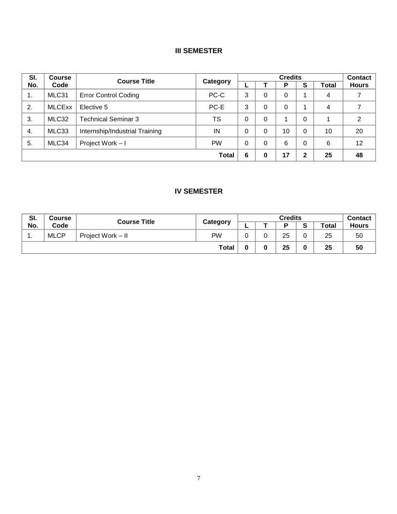
III SEMESTER
SI. No.
Course Code
Course Title Category Credits Contact
Hours L T P S Total
1. MLC31 Error Control Coding PC-C 3 0 0 1 4 7
2. MLCExx Elective 5 PC-E 3 0 0 1 4 7
3. MLC32 Technical Seminar 3 TS 0 0 1 0 1 2
4. MLC33 Internship/Industrial Training IN 0 0 10 0 10 20
5. MLC34 Project Work – I PW 0 0 6 0 6 12
Total 6 0 17 2 25 48
IV SEMESTER
SI. No.
Course Code
Course Title Category Credits Contact
Hours L T P S Total
1. MLCP Project Work – II PW 0 0 25 0 25 50
Total 0 0 25 0 25 50

8
List of Electives
SI.
No.
Course
Code Course Title Credits
L T P S Total
1. MLCE01 Digital System Design using HDL 4 0 0 0 4
2. MLCE02 Design of Electronic Systems 3 0 0 1 4
3. MLCE03 ASIC Design 3 1 0 0 4
4. MLCE04 Advanced Embedded Systems 4 0 0 0 4
5. MLCE05 Optical Communication and Networking 3 0 0 1 4
6. MLCE06 Data Compression 3 0 0 1 4
7. MLCE07 Automotive Electronics 3 0 0 1 4
8. MLCE08 Nanoelectronics 4 0 0 0 4
9. MLCE09 CMOS VLSI Design 4 0 0 0 4
10. MLCE10 Simulation, Modeling and Analysis 4 0 0 0 4
11. MLCE11 Broadband Wireless Networks 4 0 0 0 4
12. MLCE12 Spread Spectrum Communication 4 0 0 0 4
13. MLCE13 RFMEMS 3 0 0 1 4
14. MLCE14 Pattern Recognition and Analysis 3 0 0 1 4
15. MLCE15 Image and Video Processing 3 1 0 0 4
16. MLCE16 Advanced Computer Networks 3 1 0 0 4
17. MLCE17 Advances in VLSI Design 4 0 0 0 4
18. MLCE18 Advances in Radar Systems 4 0 0 0 4
19. MLCE19 Communication System Design using DSP 3 1 0 0 4
20. MLCE20 RF and Microwave Circuit Design 4 0 0 0 4

9
ADVANCED ENGINEERING MATHEMATICS
Subject Code: MLC11 Credits: 3:1:0:0
Prerequisites: Engineering Mathematics Contact Hours: 70
Course Coordinator: Mr. Sadashiva V Chakrasali
UNIT – I
Solving Linear Equations: Introduction, geometry of linear equations, Solution sets of linear
systems, Gaussian elimination, matrix notation, inverses, Partitioned matrices, matrix
factorization and determinants.
UNIT – II
Vector Spaces: Vector spaces and subspaces, linear independence, rank, basis and dimension,
linear transformation, change of basis.
Eigen values and Eigen vectors: Eigen values, Eigen vectors and diagonalization, Eigen vectors
and linear transformations.
UNIT – III
Orthogonality: Orthogonal vectors and subspaces, projections, orthogonal bases and Gram –
Schmidt orthogonalization, least - squares problems, Inner product spaces, Diagonalization of
symmetric matrices, quadratic forms, constrained optimization and SVD.
UNIT – IV
Linear Programming: Introduction – Optimization model, formulation and applications –
Classical optimization techniques: Single and multi-variable problems, Types of constraints.
Linear optimization algorithms: Simplex method, Basic solution and extreme point, Degeneracy,
Primal simplex method, Dual linear programs, Primal, dual, and duality theory, Dual simplex
method, The primal – dual algorithm, Duality applications.
UNIT – V
Nonlinear Programming: Minimization and maximization of convex functions, Local & Global
optimum, Convergence, Speed of convergence. Unconstrained optimization: One dimensional
minimization, Elimination methods: Fibonacci & Golden section search, Gradient methods,
steepest descent method. Constrained optimization: Constrained optimization with equality and
inequality constraints.
References:
1. B. S. Grewal, “Higher Engineering Mathematics”, 40th
Edition, Khanna Publishers, 2007.
10
2. Strang. G, “Linear Algebra and its Applications”, 3rd
Edition, Thomson Learning, 1988.
3. David C. Lay, “Linear Algebra and its Applications”, 3rd
Edition, Pearson Education, 2003.
4. S. S. Rao, “Engineering Optimization: Theory and Practice”, Revised 3rd
Edition, New Age
International Publishers, New Delhi, 2004.
5. Taha H A, “Operations Research – An Introduction”, McMillan Publishing Co, 1982.
Course Outcomes:
1. Employ linear systems concepts in statistical signal processing and graph theory
(POs: 1, 3, 4)
2. Use eigen values, eigen vectors and diagonalization in signal processing applications
(POs: 1, 3, 4)
3. Apply projections and SVD to image processing (POs: 1, 3, 4)
4. Execute linear optimization in various signal processing applications (POs: 1, 3, 4)
5. Employ different non-linear optimization techniques in various applications (POs: 1, 3, 4)
11
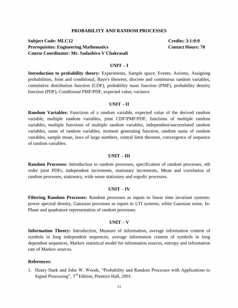
PROBABILITY AND RANDOM PROCESSES
Subject Code: MLC12 Credits: 3:1:0:0
Prerequisites: Engineering Mathematics Contact Hours: 70
Course Coordinator: Mr. Sadashiva V Chakrasali
UNIT – I
Introduction to probability theory: Experiments, Sample space, Events, Axioms, Assigning
probabilities, Joint and conditional, Baye's theorem, discrete and continuous random variables,
cumulative distribution function (CDF), probability mass function (PMF), probability density
function (PDF), Conditional PMF/PDF, expected value, variance
UNIT – II
Random Variables: Functions of a random variable, expected value of the derived random
variable, multiple random variables, joint CDF/PMF/PDF, functions of multiple random
variables, multiple functions of multiple random variables, independent/uncorrelated random
variables, sums of random variables, moment generating function, random sums of random
variables, sample mean, laws of large numbers, central limit theorem, convergence of sequence
of random variables.
UNIT – III
Random Processes: Introduction to random processes, specification of random processes, nth
order joint PDFs, independent increments, stationary increments, Mean and correlation of
random processes, stationary, wide sense stationary and ergodic processes.
UNIT – IV
Filtering Random Processes: Random processes as inputs to linear time invariant systems:
power spectral density, Gaussian processes as inputs to LTI systems, white Gaussian noise, In-
Phase and quadrature representation of random processes.
UNIT – V
Information Theory: Introduction, Measure of information, average information content of
symbols in long independent sequences, average information content of symbols in long
dependent sequences, Markov statistical model for information sources, entropy and information
rate of Markov sources.
References:
1. Henry Stark and John W. Woods, “Probability and Random Processes with Applications to
Signal Processing”, 3rd
Edition, Prentice Hall, 2001.

12
2. A. Papoulis and S. U. Pillai, “Probability, Random Variables and Stochastic Processes”, 4th
Edition, McGraw Hill, 2002.
3. Peyton Z. Peebles, “Probability, Random Variables and Random Signal Principles”, 4th
Edition, TMH, 2007.
4. K. Sam Shanmugam, “Digital and Analog Communication Systems”, John Wiley, 2004.
Course Outcomes:
1. Solve basic communication system problems using probability concepts (POs: 1, 4)
2. Apply random variables concepts to detection and estimation (POs: 1, 3, 4)
3. Model communication channels (POs: 3, 4)
4. Model linear systems employed in communication systems (POs: 3, 4)
5. Design Markov model for information sources (POs: 3, 4)

13
ANTENNA THEORY AND DESIGN
Subject Code: MLC13 Credits: 3:0:0:1
Prerequisites: Microwave Circuits Contact Hours: 42
Course Coordinator: Mrs. Sujatha B
UNIT – I
Antenna fundamental and definitions: Radiation patterns, Directivity and gain, Effective
height and aperture, Antenna impedance, Radiation efficiency.
Arrays: Array factor for linear arrays, uniformly excited equally spaced linear arrays, Pattern
multiplication, Directivity of linear arrays, Multidimensional arrays and Feeding techniques.
UNIT – II
Resonant Antennas: Dipole antenna (Far field electric and magnetic field components,
Radiation resistance), Yagi-Uda antennas.
Broadband antennas: Travelling wave antennas helical antennas, Biconical antennas and
Principles of frequency independent antennas: Log - periodic antennas.
UNIT – III
Microstrip and Printed Antennas: Feeding methods, Methods of analysis, Rectangular patch,
Circular patch, Quality factor, Bandwidth and efficiency, Coupling, Arrays and feed networks,
Printed antennas.
UNIT – IV
Antenna Array Synthesis: Formulation of the synthesis problem, Synthesis principles, Line
sources shaped beam synthesis, Linear array shaped beam synthesis, Woodward - Lawson
sampling method, Comparison of shaped beam synthesis methods, low sidelobe narrow main
beam synthesis methods, Dolph Chebyshev linear array, Method of moments: Introduction to
method of moments, Pocklington's integral equation, Integral equation.
UNIT – V
Computational EM: FD-TD methods, Maxwell‟s equations for the FD-TD method, Three-
dimensional problem formulation, two dimensional problem formulation, one dimensional
problem formulation, Computer Algorithms and FD-TD implementation, A two dimensional
example, antenna analysis and applications.
Self-Study: Solution of Maxwell's equations for radiation problems, Antenna polarization, Non-
uniformly excited equally spaced linear arrays, Phased arrays, Feed antennas for reflectors,

14
Fourier series of antenna synthesis, Taylor line source method, Kirchhoff‟s networking
equations, Source conditions, near fields and far fields.
References:
1. Warren L. Stutzman and Gary A. Thiele, “Antenna theory and design”, 2nd
Edition, John
Wiley and Sons (Wiley India edition) 2010.
2. Constantine. A. Balanis, “Antenna Theory Analysis and Design”, 2nd
Edition, John Wiley,
1997.
3. John D Kraus, Ronald J Marhefka, Ahmad S Khan, “Antennas”, 4th
Edition, Tata McGraw
Hill, 2006.
Course Outcomes:
1. Recall the Maxwell‟s equations to find the field components, parameters and radiation
resistance of resonant antennas. (POs: 1, 3, 4)
2. Analyze the uniform and non-uniform excited arrays and broad band antennas. (POs: 3, 4)
3. Design different types of patch antennas and analyze their feed methods, quality factor,
bandwidth and efficiency. (POs: 1, 3, 4)
4. Synthesize antenna beam pattern using different types of distributions. (POs: 3, 4)
5. Describe the computationally efficient approximations to calculate antenna performance
using FTTD methods and geometrical optics. (POs: 3, 4)

15
DIGITAL SYSTEM DESIGN LABORATORY
Subject Code: MLCL14 Credits: 0:0:2:0
Prerequisites: Digital Electronic Circuits Contact Hours: 56
Course Coordinator: Dr. V. Anandi
LIST OF EXPERIMENTS
Laboratories are scheduled for the design of digital combinational and sequential circuits using
HDL and implementation on FPGA using Xilinx software.
1. The use of EDA Tools for simulation and synthesis using FPGA – Introduction
Logic gates, 2 to 4 decoder
Minimal-length binary code to represent the state of a phone: on hook, dial-tone,
dialing, busy, connected, disconnected, and ringing
Full adder using different modeling styles
2. Digital Combinational Circuit Modeling and Verification using VHDL
Full subtractor using structural modeling and test bench
4 bit ripple carry adder using full adders with test bench
4 bit signed and unsigned comparator
3:8 decoder with test bench
Encoder with and without priority
Parity generator and parity checker
3. Digital Combinational Circuit Modeling and Verification using Verilog
Bit carry look ahead adder using dataflow modeling and test bench
Simulate the behavior of a 4 bit array multiplier
Simulate the behavior of 8 bit Booth multiplier
4. Digital Sequential Circuit Modeling using VHDL
3 bit counter with synchronous reset and test bench
4 bit BCD to Hexadecimal and test bench
Simulate 4-bit mod-13 counter and test
Modulus counter with JK flip flops as components with asynchronous reset
4 bit shift register
4 bit GRAY counter with asynchronous reset
4 bit Ring and Johnson counter with asynchronous reset
Simulate 4-bit register with shift left and shift right modes of operation
Simulate and test JK FF with asynchronous reset
5. Synthesis of digital circuits using FPGA
4 bit BCD counter and synthesize on FPGA
Synthesize 4 bit binary up –down counter with synchronous reset
Synthesize a 4-bit BCD counter with asynchronous reset

16
BCD to seven segment decoder and display the result on seven segment display
Simulate a 4 bit Carry Select Adder and synthesize on FPGA board
Simulate a 4 bit CSA and Synthesize on FPGA board
Synthesize 3 bit ALU
6. FSMs in HDL: Traffic light controller/Vending machine
7. Serial adder as FSM simulation and synthesis
8. Interface experiments: Stepper motor, DAC
References:
1. J Bhaskar, “HDL Primer”, 3rd
Edition, B S Publications, 2005.
2. Peter J. Ashenden, “Digital Design: An Embedded Systems Approach using VHDL”,
Elsevier, 2010.
3. Peter J. Ashenden, “Digital Design: An Embedded Systems Approach using Verilog”,
Elsevier, 2010.
Course Outcomes:
1. Employ modern EDA tools for digital design including simulation and synthesis suitable for
implementation on programmable device technologies and understand design tradeoffs.
(POs: 3, 5)
2. Design, test and implement combinational circuits, in HDL to verify their functionality.
(POs: 3, 4, 5)
3. Design and implement existing SSI and MSI sequential digital circuits with HDL
(POs: 3, 4, 5)
4. Design and implement arithmetic circuits with HDL (POs: 3, 5)
5. Design and implement complex FSMs with HDL on FPGA (POs: 3, 4, 5)
17
ANTENNAS LABORATORY
Subject Code: MLCL15 Credits: 0:0:2:0
Prerequisites: Microwave Circuits and Components Contact Hours: 56
Course Coordinator: Mrs. Sujatha B
Experiments can be done using Hardware tools such as Spectrum analyzers, Signal sources,
Power Supplies, Oscilloscopes, High frequency signal sources, fiber kits, Measurement benches,
Logic analyzers, PC setups, etc. Software tools based experiments can be done using, FEKO
simulator, NS2 simulator, MATLAB, etc.
LIST OF EXPERIMENTS
1. Experimental studies of radiation pattern of Micro strip Yagi-Uda and patch antennas.
2. Impedance measurements of Horn/Yagi/dipole/Parabolic antennas
3. Analysis of E & H plane horns
4. Determine the directivity and gains of Horn/ Yagi/ dipole/ Parabolic antennas
5. Determination of the modes transit time, electronic timing range and sensitivity of klystron
source
6. Conduct an experiment for voice and data multiplexing using optical fiber.
7. Determination of V-I characteristics of GUNN diode, and measurement of guide wave
length, frequency, and VSWR
8. Determination of coupling coefficient and insertion loss of Branch line and backward
directional couplers
9. Matlab/C implementation to obtain the radiation pattern of different types of antennas
10. Matlab/C implementation of n-isotropic sources to obtain Beam area, Beam width between
first nulls, and Directivity of End fire antenna array
11. Matlab/C implementation of n-isotropic sources to obtain Beam area, Beam width between
first nulls, and Directivity of broad side antenna array
12. Measurement techniques of radiation characteristics of an antenna
References:
1. John D Kraus, Ronald J Marhefka, Ahmad S Khan, “Antennas”, 4th
Edition, Tata McGraw
Hill, 2006.
2. Constantine. A. Balanis, “Antenna Theory Analysis and Design”, 2nd
Edition, John Wiley,
1997.
Course Outcomes:
1. Plot the radiation pattern of different types of antennas (POs: 1, 3, 4)
2. Determine the parameters like gain, beam width and directivity of antennas (POs: 1, 3, 4)
3. Conduct an experiment to analyze voice and data multiplexing using optical fiber kit
(POs: 1, 3, 4)

18
4. Design antenna array and find the various parameters like directivity and gain by plotting the
radiation pattern (POs: 1, 3, 4)
5. Measure the coupling coefficient and losses of directional couplers (POs: 1, 3, 4)

19
TECHNICAL SEMINAR – I
Subject Code: MLC16 Credits: 0:0:1:0 Prerequisites: Nil Contact Hours: 28
Students will perform an initial literature survey and choose software tools for realizing solutions to a
technical problem identified. Evaluation will be based on two oral presentations during the semester,
for which rubrics are defined as given below.
Evaluation Rubrics
Criteria Max.
Marks
Achievement Levels CO
Mapping Inadequate
(0% – 33 %)
Developing
(34% – 66%)
Proficient
(67% – 100%)
Marks
Awarded
Introduction
to area
10 No
information
about the
specific
technical
details in the
chosen area.
Some
information
available, but
no clarity in
internal details.
Clear presentation
of the technical
details, internal
working, and
rationale of design
choices.
CO1,
CO2
Literature
Survey
10 Very few
quality
sources
pertinent to
the chosen
technical area.
No recent
articles used.
Ample sources
from recent
past, but not
from quality
sources or with
zero or very
few citations.
Ample sources
from quality
journals and
conferences
recently
published, and
having abundant
citations.
CO1,
CO2
Problem
Statement
10 No clear
problem
identified in
chosen area.
Identification
of problem
area, but no
knowledge of
underlying
technical
details.
Clear
identification of
problem area,
along with
parameters having
an influence on
the performance.
CO3
Reproduction
of Existing
Results
10 No simulation
results shown.
Individual
blocks
simulated, but
no
comprehensive
simulation.
Complete and
consistent
reproduction of
existing results
using appropriate
software tools.
CO4
Research
Questions
10 No hypothesis
proposed.
Hypothesis is
not
sound/practical,
and not backed
by technical
arguments.
Sound and
practical
hypothesis
proposed, along
with supporting
technical/intuitive
arguments.
CO5
TOTAL MARKS AWARDED
20
Course Outcomes:
1. Identify a technical problem by performing a comprehensive literature survey.
(POs: 1, 2, 3, 5)
2. Compare different solution methods presented in the literature for the technical problem
identified. (POs: 1, 2, 3, 5)
3. Predict the impact of various software tools and methods for the identified problem.
(POs: 1, 2, 3, 5)
4. Display initial simulation results, showing replication of existing approaches for the
identified problem. (POs: 1, 2, 3, 5)
5. Construct a technical block diagram that shows an optimized solution for the identified
problem, with respect to existing literature. (POs: 1, 2, 3, 4, 5)

21
WIRELESS COMMUNICATIONS
Subject Code: MLC21 Credits: 3:0:0:1
Prerequisites: Digital Communication Contact Hours: 42
Course Coordinator: Mrs. Sarala S M
UNIT – I
Wireless Channel: Physical modeling for wireless channels, input/output model of wireless
channel, time and frequency response, statistical models.
Point to Point Communication: Detection in Rayleigh fading channel, Repetition Coding,
Orthogonal Frequency Division Multiplexing.
UNIT – II
Diversity: Introduction, Micro-diversity, Macro-diversity and simulcast, Combination of
Signals, Error Probability in fading channels with diversity Reception, transmit diversity.
UNIT – III
Capacity of Wireless Channels: AWGN channel capacity, linear time invariant Gaussian
channels, capacity of fading channels.
UNIT – IV
Antenna Diversity: Receive diversity, Spatial multiplexing and channel modeling, multiplexing
capability of MIMO channels, physical modeling of MIMO channels, modeling MIMO fading
channels.
UNIT – V
MIMO Capacity and Multiplexing Architectures: V-BLAST architecture, Fast fading MIMO
channels, Receiver architectures: Linear de-correlator, Successive cancellation, Linear MMSE
receiver, D-BLAST architecture.
Self-Study: Wireless channel as a linear time-varying system, Reflection from a ground plane,
Power decay with distance and shadowing, Baseband equivalent channel model, Singular value
decomposition of AWGN channel, Concepts of multiple access techniques (FDMA, TDMA, and
CDMA), Basics of spread spectrum communication systems.
22
References:
1. David Tse, P. Viswanath, “Fundamentals of Wireless Communication”, Cambridge, 2006.
2. Andreas Molisch, “Wireless Communications”, Wiley Publications, 2009.
3. William C Y Lee, “Mobile Communication Engineering Theory and Applications”, TMGH,
2008.
4. Upen Dalal, “Wireless Communication”, Oxford Publications, 2009.
5. Mark Ciampa, Jorge Olenwa, “Wireless Communications”, Cengage Publishers, 2007.
Course Outcomes:
1. Define characteristics of wireless channel strength over time and frequency. (POs: 1, 2, 4)
2. Employ the concept of different diversity techniques to overcome the effect of small scale
multi-path propagation. (POs: 1, 2, 4)
3. Demonstrate the impact of channel uncertainty on the performance of diversity combining
schemes. (POs: 1, 2, 4)
4. Employ the multiple transmit and multiple receive antennas under suitable channel fading
conditions. (POs: 1, 2, 4)
5. Discuss the performance of MIMO receiver architecture. (POs: 1, 2, 4)

23
ADVANCED DIGITAL SIGNAL PROCESSING
Subject Code: MLC22 Credits: 3:1:0:0
Prerequisites: Digital Signal Processing Contact Hours: 70
Course Coordinator: Dr. Maya V. Karki
UNIT – I
Introduction and Discrete Fourier Transforms: Signals, systems and processing,
Classification of signals, concept of frequency in continuous time and discrete time signals,
Analog to digital and digital to analog conversion, Frequency domain sampling, Discrete Fourier
transform, Properties of the DFT, Linear filtering methods based on the DFT.
UNIT – II
Design of Digital Filters: General considerations, design of FIR filters, design of IIR filters
from analog filters, Frequency transformations.
UNIT – III
Multirate Digital Signal Processing: Introduction, decimation by a factor 'D', Interpolation by a
factor 'I', sampling rate conversion by a factor 'I/D', Implementation of sampling rate conversion,
Multistage implementation of sampling rate conversion, Sampling rate conversion of band pass
signals, Sampling rate conversion by an arbitrary factor, Applications of multirate signal
processing, Digital filter banks, two channel quadrature mirror filter banks, M-channel QMF
bank.
UNIT – IV
Linear Prediction & Optimum Linear Filters: Random Signals, Correlation Functions and
Power Spectra, Innovations Representation of a Stationary Random Process, Forward and
Backward Linear Prediction, Solution of the Normal Equations, Properties of the Linear
Prediction-Error Filters, Lattice and ARMA Lattice-Ladder Filters, Wiener Filters for Filtering
and Prediction
UNIT – V
Adaptive Filters: Applications of adaptive filters, Adaptive direct form FIR filters, The LMS
algorithm, Adaptive direct form filters, RLS algorithm.
References:
1. Proakis and Manolakis, “Digital Signal Processing”, 4th
Edition, Prentice Hall, 2006.
2. Robert. O. Cristi, “Modern Digital Signal Processing”, Cengage Publishers, India, 2003.
3. S. K. Mitra, “Digital Signal Processing: A computer based approach”, 3rd
Edition, TMH,
India, 2007.
24
4. E. C. Ifeachor, and B. W. Jarvis, “Digital Signal Processing: A Practitioner's approach”, 2nd
Edition, Pearson Education, India, 2002.
Course Outcomes:
1. Analyze different signals and systems both in time and frequency domain (POs: 1, 3, 4)
2. Appreciate decimation, interpolation and sampling rate conversion (POs: 1, 3, 4)
3. Design IIR and FIR filters for different specifications and applications (POs: 1, 3, 4)
4. Develop linear predictors and optimum linear filters (POs: 1, 3, 4)
5. Design adaptive filters with LMS and RLS algorithms (POs: 1, 3, 4)
25
ADVANCED DIGITAL COMMUNICATION
Subject Code: MLC23 Credits: 3:0:0:1
Prerequisites: Digital Communication Contact Hours: 42
Course Coordinator: Mr. Sadashiva V Chakrasali
UNIT – I
Digital Modulation Techniques: Digital modulation formats, Coherent binary modulation
techniques, Coherent quadrature – modulation techniques, Non-coherent binary modulation
techniques, Comparison of binary and quaternary modulation techniques, M-ary modulation
techniques, Power spectra, Bandwidth efficiency, M-ary modulation formats viewed in the light
of the channel capacity theorem, Effect of inter symbol interference, Bit vs symbol error
probabilities.
UNIT – II
Communication Through Band Limited Linear Filter Channels: Optimum receiver for
channel with ISI and AWGN, Linear equalization, Decision feedback equalization, reduced
complexity ML detectors.
UNIT – III
Adaptive Equalization: Adaptive linear equalizer, adaptive decision feedback equalizer,
adaptive equalization of Trellis - coded signals, Recursive least squares algorithms for adaptive
equalization.
UNIT – IV
Spread Spectrum Signals for Digital Communication: Model of Spread Spectrum Digital
Communication System, Direct Sequence Spread Spectrum Signals, Frequency-Hopped Spread
Spectrum Signals.
UNIT – V
Digital Communication Through Fading Multi-Path Channels: Characterization of fading
multipath channels, the effect of signal characteristics on the choice of a channel model,
frequency-nonselective, slowly fading channel, diversity techniques for fading multi-path
channels, Digital signaling over a frequency-selective, slowly fading channel.
Self-Study: Synchronization, Applications, Iterative equalization and decoding, Turbo
equalization, self-recovering (blind) equalization, CDMA, time-hopping SS, Synchronization of
SS systems, multiple antenna systems.
26
References:
1. John G. Proakis, “Digital Communications”, 4th
Edition, McGraw Hill, 2001.
2. Simon Haykin, “Digital Communications”, John Wiley and Sons, 2013.
3. Bernard Sklar, “Digital Communications - Fundamentals and Applications”, 2nd
Edition,
Pearson Education (Asia) Pvt. Ltd, 2001.
4. Andrew J. Viterbi, “CDMA: Principles of Spread Spectrum Communications”, Prentice Hall,
USA, 1995.
Course Outcomes:
1. Compare and analyze power spectra of linearly modulated signals (POs: 3, 4)
2. Explain linear equalization and derive its performance characteristics for channels with
intersymbol interference and AWGN (POs: 1, 3, 4)
3. Analyze adaptive equalization algorithms with LMS and RLS techniques (POs: 3, 4)
4. Describe different spread spectrum signals and systems (POs: 1, 3, 4)
5. Derive signal design, receiver structure, and receiver performance of fading multipath
channels (POs: 3, 4)

27
DIGITAL SIGNAL PROCESSING LABORATORY
Subject Code: MLCL24 Credits: 0:0:2:0
Prerequisites: Digital Signal Processing Contact Hours: 56
Course Coordinator: Dr. Maya V. Karki
LIST OF EXPERIMENTS
1. A LTI system is defined by the difference equation y[n] = x[n] + x[n - 1] + x[n - 2].
a. Determine the impulse response of the system and sketch it.
b. Determine the output y[n] of the system when the input is x[n] = u[n].
c. Determine the output of the system when the input is a complex exponential (E.g.
x[n] = 2*exp(j0.26n)).
2. Design a simple digital FIR filter with real coefficient to remove a narrowband i.e.,
sinusoidal) disturbance with frequency fo = 50Hz. Let fs = 300Hz be the sampling frequency.
a. Determine the desired zeros and poles of the filter.
b. Determine the filter coefficients with the gain K = 1.
c. Sketch the magnitude of the frequency response.
3. Design an IIR filter with real coefficients for same specifications mentioned in Q2 and
repeats the steps (a) to (c).
4. Generate a signal with two frequencies x(t)=3cos(2*pi*f1*t) + 2cos(2*pi*f2*t) sampled at fs
= 8kHz. Let f1 = 1kHz and f2 = f1+'A‟ and the overall data length be N = 256 points.
a. From theory, determine the minimum value of 'A' necessary to distinguish between
the two frequencies.
b. Verify this result experimentally, using the rectangular window, look at the DFT
with several values of 'A' so that you verify the resolution.
c. Repeat part (b) using a Hamming window. How did the resolution change?
5. Comparison of DFT and DCT (in terms of energy compactness)
Generate the sequence x[n] = n – 64, for n = 0...127.
(a) Let X[k] = DFT{x[n]}. For various values of L, set to zero "high frequency
coefficients" X[64-l]= ....X[64]= ......X[64+L]=0 and take the inverse DFT. Plot the
results.
(b) Let XDCT[k] = DCT(X[n]). For the same values of L, set to zero "high frequency
coefficient" XDCT[127-L] = ....XDCT[127]. Take the inverse DCT for each case and
compare the reconstruction with the previous case.
6. Filter design:
Design a discrete low pass filter with the specification given below:
Sampling frequency = 2kHz
Passband edge = 260Hz
Stop band edge = 340Hz
Max. passband attenuation= 0.1dB

28
Minimum stop band attenuation = 30dB
Use the following design methodologies:
Hamming Windowing
Kaiser Windowing
Apply Bilinear transformation to a suitable Butterworth filter. Compare the obtained filters in
terms of performance (accuracy in meeting specifications and computational complexity).
List of experiments to be done using the DSP processor
1. Write an ALP to obtain the response of a system using linear convolution whose input
and impulse response coefficients are specified.
2. Write an ALP to obtain the impulse response of the given system, given the difference
equation.
3. Sampling of an image
4. Design of equiripple filters
5. Applications of frequency transformation in filter design
6. Computation of FFT when N is not a power of 2
7. Sampling rate conversion and plot of spectrum
8. Analysis of signals by STFT and WT
9. Delayed auditory feedback signal using 6713 processor
10. Record of machinery noise like fan or blower or diesel generator and obtaining its
spectrum
11. Synthesis of select dual tone multi frequency using 6713 processor
12. Fourier Transform and its inverse Fourier transform of an image
References:
1. Proakis and Manolakis, “Digital Signal Processing”, 4th
Edition, Prentice Hall, 2006.
2. Rulph Chassing and Donald Reay, “Digital Signal Processing and Applications with
TMS320C6713 and TMS320C6416 DSK”, 2nd
Edition, John Wiley and Sons, 2010.
Course Outcomes:
1. Analyze outputs of different LTI systems. (POs: 1, 4)
2. Design IIR and FIR filters for the given cutoff frequency. (POs: 1, 4)
3. Compute DFT and DCT through examples. (PO: 1)
4. Illustrate signal analysis algorithms on DSP boards. (POs: 1, 3)
5. Implement simple image processing algorithms on DSP boards. (POs: 1, 3)

29
ADVANCED EMBEDDED SYSTEMS LABORATORY
Subject Code: MLCL25 Credits: 0:0:2:0
Prerequisites: Microcontrollers Contact Hours: 56
Course Coordinator: Mrs. Lakshmi Shrinivasan
LIST OF EXPERIMENTS
Introduction to IAR Workbench for ARM Cortex M4
1. Assembly language data transfer programs
2. Factorial of a number and Fibonacci series generation
3. Parity checking (odd or even), Ascending/Descending order of given N number of data
4. Logical instruction based programs
5. Array arithmetic operations (multiplication, addition and subtraction)
6. Handling of external interrupts
7. Elaborating the usage of low power modes
Hardware Interfacing Experiments using ARM Cortex M4
8. Design and interface a 16 channel 8 bit ADC
9. Design and interface a DC motor speed control and measurement
10. Generation of sine and square waveform using Dual DAC for given duty cycle and
amplitude
11. Design and interface a simple temperature monitoring and control system
12. Design and interface a stepper motor for following operations: rotate clockwise,
anticlockwise for defined degree of angle
13. Implement and interface real time clock (RTC)
14. Design and interface a simple 4 x 4 calculator type Keypad module
15. Show how an output interfaced hardware module could be controlled using relay
Programs based on RTOS concepts in Linux environment
16. Introduction to Linux commands
17. Create a process using fork() function call (forkdemo.c) and simulate it
18. Create „n‟ number of child threads. Each thread p prints the message “I‟m in thread
number…” and sleeps for 50ms and then quits. The main thread waits for complete
execution of all the child threads. Compile and execute it.
19. Generate a signal when a delete key is pressed (signal) compile and simulate it.
20. Show IPC using Semaphore and Mutex.
Model the given embedded system using UML tool
21. Static aspects of the system using basic Class Diagram and generate code

30
22. The elevator system for the above mentioned scenario using sequence diagram
23. Dynamic aspects of the system using sequence diagram and generate code
References:
1. Joseph Yiu, “The definitive guide to ARM Cortex – M3 and Cortex- M4 processors”,
Elsevier Publishing, 2014.
2. Shibu K V, “Introduction to Embedded Systems”, Tata McGraw Hill Education Private
Limited, 2009.
Course Outcomes:
1. Use simulation and emulation IDE (PO: 5)
2. Write, compile and debug RTOS concepts programs (POs: 1, 2, 3, 5)
3. Interface and communicate peripheral modules to ARM Cortex M4 microcontroller
(POs: 1, 2, 4, 5)
4. Develop various UML diagrams and models for an embedded system (POs: 1, 2, 4, 5)
5. Prepare a report with algorithm and expected output (PO: 2)
31
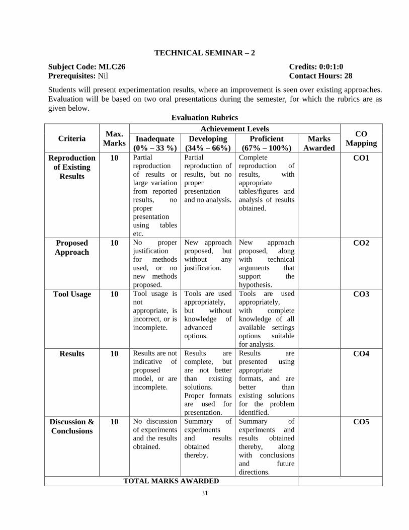
TECHNICAL SEMINAR – 2
Subject Code: MLC26 Credits: 0:0:1:0 Prerequisites: Nil Contact Hours: 28
Students will present experimentation results, where an improvement is seen over existing approaches.
Evaluation will be based on two oral presentations during the semester, for which the rubrics are as
given below.
Evaluation Rubrics
Criteria Max.
Marks
Achievement Levels CO
Mapping Inadequate
(0% – 33 %)
Developing
(34% – 66%)
Proficient
(67% – 100%)
Marks
Awarded
Reproduction
of Existing
Results
10 Partial
reproduction
of results or
large variation
from reported
results, no
proper
presentation
using tables
etc.
Partial
reproduction of
results, but no
proper
presentation
and no analysis.
Complete
reproduction of
results, with
appropriate
tables/figures and
analysis of results
obtained.
CO1
Proposed
Approach
10 No proper
justification
for methods
used, or no
new methods
proposed.
New approach
proposed, but
without any
justification.
New approach
proposed, along
with technical
arguments that
support the
hypothesis.
CO2
Tool Usage 10 Tool usage is
not
appropriate, is
incorrect, or is
incomplete.
Tools are used
appropriately,
but without
knowledge of
advanced
options.
Tools are used
appropriately,
with complete
knowledge of all
available settings
options suitable
for analysis.
CO3
Results 10 Results are not
indicative of
proposed
model, or are
incomplete.
Results are
complete, but
are not better
than existing
solutions.
Proper formats
are used for
presentation.
Results are
presented using
appropriate
formats, and are
better than
existing solutions
for the problem
identified.
CO4
Discussion &
Conclusions
10 No discussion
of experiments
and the results
obtained.
Summary of
experiments
and results
obtained
thereby.
Summary of
experiments and
results obtained
thereby, along
with conclusions
and future
directions.
CO5
TOTAL MARKS AWARDED

32
Course Outcomes:
1. Present initial simulation results, replicating existing findings. (POs: 1, 2, 3, 4, 5)
2. Propose a technical block diagram with arguments for improved performance.
(POs: 1, 2, 3, 4, 5)
3. Present the tools required for performing experiments, and justify their appropriateness.
(POs: 1, 2, 3, 4, 5)
4. Discuss simulation results and optimized performance metrics. (POs: 1, 2, 3, 4, 5)
5. Discuss the advantages and disadvantages of approach, along with possible future directions.
(POs: 1, 2, 3, 4, 5)
33
ERROR CONTROL CODING
Subject Code: MLC31 Credits: 3:0:0:1
Prerequisites: Information Theory and Coding Contact Hours: 42
Course Coordinator: Mrs. Chitra M
UNIT – I
Introduction to Algebra: Groups, Fields, binary field arithmetic, Construction of Galois Field
GF (2m
) and its properties, Computation using Galois filed GF (2m
) arithmetic, Vector spaces and
matrices on Galois field.
UNIT – II
Linear Block Codes: Generator and parity check matrices, Encoding circuits, Syndrome and
error detection, Minimum distance considerations, Error detecting and error correcting
capabilities, Standard array and syndrome decoding, decoding circuits, Hamming codes, Reed-
Muller codes, Golay codes, Product codes and interleaved codes.
UNIT – III
Cyclic Codes: Introduction, Generator and parity check polynomials, Encoding using
multiplication circuits, Systematic cyclic codes – Encoding using feedback shift register circuits,
generator matrix for cyclic code, Syndrome computing and error detection, Meggitt decoder,
Error trapping decoding, Cyclic hamming codes, Golay code, Shortened cyclic codes.
UNIT – IV
BCH Codes: Binary primitive BCH codes, Decoding procedures, Implementation of Galois field
arithmetic, Implementation of error correction.
Non-binary BCH Codes: q-ary linear block codes, Primitive BCH codes over GF(q), Reed -
Solomon codes, decoding of non-binary BCH and RS codes: The Berlekamp - Massey
Algorithm, Gorenstein – Zierler Algorithm.
UNIT – V
Majority Logic Decodable Codes & Convolutional Codes: One step majority logic decoding,
one step majority logic decodable codes, Two-step majority logic decoding, Multiple-step
majority logic decoding.
Convolutional Codes: Encoding of convolutional codes, Structural properties, Distance
properties, Viterbi decoding algorithm for decoding, soft output Viterbi algorithm, Stack and
Fano sequential decoding algorithms, Majority logic decoding.
34
Introduction to Turbo coding and their distance properties, design of Turbo codes
Self-Study: Basic properties of GF (2m
), example of construction of GF (25) using primitive
polynomial, Standard array and Syndrome decoding of linear block codes, Decoding circuits,
Product and interleaved codes, Error trapping decoding, Cyclic Hamming codes, Shortened
cyclic codes, Decoding of RS codes, Burst and random error correcting codes, concept of
interleaving.
References:
1. Shu Lin and Daniel J. Costello. Jr, “Error control coding”, 2nd
Edition, Pearson/Prentice Hall,
2010.
2. Blahut. R. E, “Theory and practice of error control codes”, Addison Wesley, 1984.
Course Outcomes:
1. Apply properties of Galois Field to Groups, Fields, Vector Spaces, row space and sub-spaces
(POs: 1, 3, 4)
2. Describe linear block codes, RM codes, Golay codes in error detection and error correction
(POs: 1, 3, 4)
3. Demonstrate cyclic block codes, cyclic Hamming codes, Shortened cyclic codes and (23, 12)
Golay codes in error detection and correction. (POs: 1, 3, 4)
4. Illustrate various BCH Codes, RS Codes and other q-ary codes and apply them for error
detection & correction. (POs: 1, 3, 4)
5. Construct state tables, state diagrams, code-tree diagram and trellis diagrams for
convolutional encoders and other higher-order error-control codes and use Viterbi and stack
algorithms for decoding those codes. (POs: 1, 3, 4)

35
TECHNICAL SEMINAR – 3
Subject code: MLC32 Credits: 0:0:1:0 Prerequisites: Nil Contact Hours: 28
Students will be evaluated based on presentation skills and technical report writing. Evaluation will be
based on two oral presentations during the semester, for which rubrics are as given below.
Evaluation Rubrics
Criteria Max.
Marks
Achievement Levels CO
Mapping Inadequate
(0% – 33 %)
Developing
(34% – 66%)
Proficient
(67% – 100%)
Marks
Awarded
Presentation
of Research
Problem
10 No clear
presentation
of recent
approaches.
Brief and
clear
presentation
of recent
research
approaches
Brief and clear
presentation of
recent
approaches,
along with
appropriate
charts/tables etc.,
to compare
different
methods.
CO1
Introduction
of Technical
Domain
10 No grasp of
technical
domain, and
no proper
organization
of technical
details.
Information is
presented in
logical
sequence, but
with only
understanding
of basic
concepts.
Information is
presented in a
logical sequence,
and student is
able to respond
to basic and
advanced
queries.
CO2
Detailed
Analysis of
Technical
Domain
10 No proper
technical
language
used,
brief/no
description
of methods.
Detailed
technical
descriptions,
but no proper
flow of
contents.
Detailed
technical
description along
with a consistent
flow of
explanations in
the document.
CO3
Thorough
Literature
Survey
10 Few low
quality
publications
referenced,
with no
summaries of
methods
provided.
Detailed
summaries of
methods
provided, but
quality of
publications
chosen is not
suitable.
High quality,
highly cited
publications
chosen, and a
detailed
document
presenting the
approaches, their
advantages and
disadvantages.
CO4

36
Course Outcomes:
1. Introduce the research problem clearly with appropriate data and figures. (POs: 1, 2, 3, 4)
2. Demonstrate extensive knowledge of the topic identified. (POs: 1, 2, 3, 4)
3. Create a document with accurate and key concepts, using appropriate diagrams/tables to
present an introduction to the problem area identified. (POs: 1, 2, 3, 4)
4. Create a document that presents a detailed survey of literature, with proper explanations and
elaborations of recent advances in problem area. (POs: 1, 2, 3, 4)
5. Create a document giving details of initial experimentation and a discussion of the obtained
results. (POs: 1, 2, 3, 4)
Discussion of
Initial
Results
10 Initial results
are absent, or
are not
simulated
appropriately
Initial results
are not
presented
appropriately,
with no
analysis/discu
ssions.
Initial results are
presented
appropriately,
along with a
discussion on
dependence of
parameters on
design.
CO5
TOTAL MARKS AWARDED
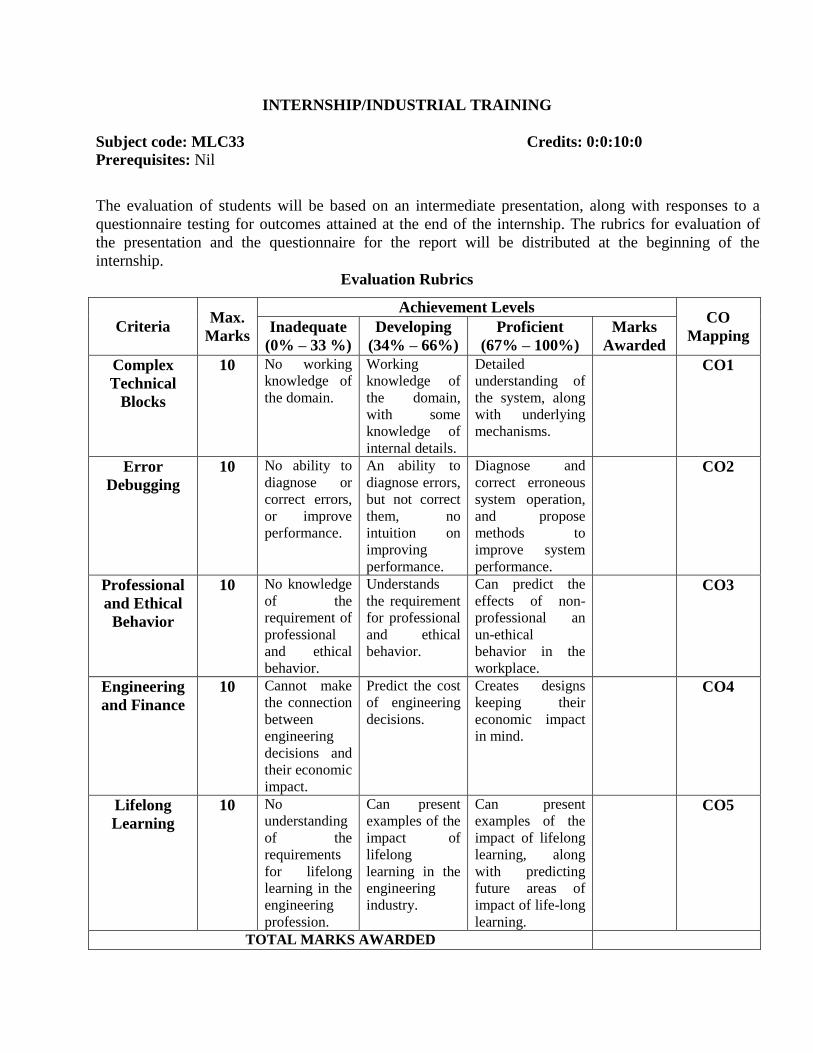
INTERNSHIP/INDUSTRIAL TRAINING
Subject code: MLC33 Credits: 0:0:10:0 Prerequisites: Nil
The evaluation of students will be based on an intermediate presentation, along with responses to a
questionnaire testing for outcomes attained at the end of the internship. The rubrics for evaluation of
the presentation and the questionnaire for the report will be distributed at the beginning of the
internship.
Evaluation Rubrics
Criteria Max.
Marks
Achievement Levels CO
Mapping Inadequate
(0% – 33 %)
Developing
(34% – 66%)
Proficient
(67% – 100%)
Marks
Awarded
Complex
Technical
Blocks
10 No working
knowledge of
the domain.
Working
knowledge of
the domain,
with some
knowledge of
internal details.
Detailed
understanding of
the system, along
with underlying
mechanisms.
CO1
Error
Debugging
10 No ability to
diagnose or
correct errors,
or improve
performance.
An ability to
diagnose errors,
but not correct
them, no
intuition on
improving
performance.
Diagnose and
correct erroneous
system operation,
and propose
methods to
improve system
performance.
CO2
Professional
and Ethical
Behavior
10 No knowledge
of the
requirement of
professional
and ethical
behavior.
Understands
the requirement
for professional
and ethical
behavior.
Can predict the
effects of non-
professional an
un-ethical
behavior in the
workplace.
CO3
Engineering
and Finance
10 Cannot make
the connection
between
engineering
decisions and
their economic
impact.
Predict the cost
of engineering
decisions.
Creates designs
keeping their
economic impact
in mind.
CO4
Lifelong
Learning
10 No
understanding
of the
requirements
for lifelong
learning in the
engineering
profession.
Can present
examples of the
impact of
lifelong
learning in the
engineering
industry.
Can present
examples of the
impact of lifelong
learning, along
with predicting
future areas of
impact of life-long
learning.
CO5
TOTAL MARKS AWARDED

38
Course Outcomes:
1. Analyze the working of complex technical systems/blocks. (POs: 1, 3, 4)
2. Correct errors during functioning and improve the performance of complex technical
systems/blocks. (POs: 1, 3, 4)
3. Understand the importance of professional and ethical behavior in the engineering
workplace. (POs: 1, 3, 4)
4. Predict the effect of engineering decisions on financial matters. (POs: 1, 3, 4)
5. Appreciate the requirements for constant technology updation. (POs: 1, 3, 4)
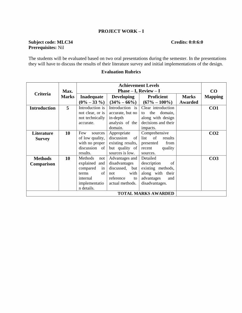
PROJECT WORK – I
Subject code: MLC34 Credits: 0:0:6:0 Prerequisites: Nil
The students will be evaluated based on two oral presentations during the semester. In the presentations
they will have to discuss the results of their literature survey and initial implementations of the design.
Evaluation Rubrics
Criteria Max.
Marks
Achievement Levels
Phase – I, Review – I CO
Mapping Inadequate
(0% – 33 %)
Developing
(34% – 66%)
Proficient
(67% – 100%)
Marks
Awarded
Introduction 5 Introduction is
not clear, or is
not technically
accurate.
Introduction is
accurate, but no
in-depth
analysis of the
domain.
Clear introduction
to the domain,
along with design
decisions and their
impacts.
CO1
Literature
Survey
10 Few sources
of low quality,
with no proper
discussion of
results.
Appropriate
discussion of
existing results,
but quality of
sources is low.
Comprehensive
list of results
presented from
recent quality
sources.
CO2
Methods
Comparison
10 Methods not
explained and
compared in
terms of
internal
implementatio
n details.
Advantages and
disadvantages
discussed, but
not with
reference to
actual methods.
Detailed
description of
existing methods,
along with their
advantages and
disadvantages.
CO3
TOTAL MARKS AWARDED
40
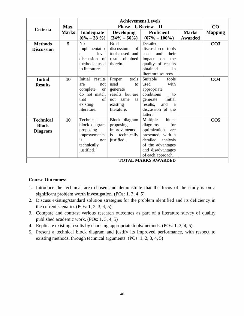
Course Outcomes:
1. Introduce the technical area chosen and demonstrate that the focus of the study is on a
significant problem worth investigation. (POs: 1, 3, 4, 5)
2. Discuss existing/standard solution strategies for the problem identified and its deficiency in
the current scenario. (POs: 1, 2, 3, 4, 5)
3. Compare and contrast various research outcomes as part of a literature survey of quality
published academic work. (POs: 1, 3, 4, 5)
4. Replicate existing results by choosing appropriate tools/methods. (POs: 1, 3, 4, 5)
5. Present a technical block diagram and justify its improved performance, with respect to
existing methods, through technical arguments. (POs: 1, 2, 3, 4, 5)
Criteria Max.
Marks
Achievement Levels
Phase – I, Review – II CO
Mapping Inadequate
(0% – 33 %)
Developing
(34% – 66%)
Proficient
(67% – 100%)
Marks
Awarded
Methods
Discussion
5 No
implementatio
n level
discussion of
methods used
in literature.
Brief
discussion of
tools used and
results obtained
therein.
Detailed
discussion of tools
used and their
impact on the
quality of results
obtained in
literature sources.
CO3
Initial
Results
10 Initial results
are not
complete, or
do not match
that of
existing
literature.
Proper tools
used to
generate
results, but are
not same as
existing
literature.
Suitable tools
used with
appropriate
conditions to
generate initial
results, and a
discussion of the
latter.
CO4
Technical
Block
Diagram
10 Technical
block diagram
proposing
improvements
is not
technically
justified.
Block diagram
proposing
improvements
is technically
justified.
Multiple block
diagrams for
optimization are
presented, with a
detailed analysis
of the advantages
and disadvantages
of each approach.
CO5
TOTAL MARKS AWARDED

41
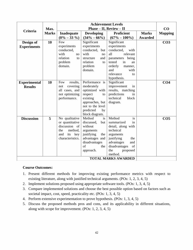
PROJECT WORK – II
Subject code: MLCP Credits: 0:0:25:0 Prerequisites: Nil
The students will be evaluated based on two oral presentations, in which they will present their
proposed solutions to the problem identified, and discuss the implementation details and results
obtained.
Evaluation Rubrics
Criteria Max.
Marks
Achievement Levels
Phase – II, Review – I CO
Mapping Inadequate
(0% – 33 %)
Developing
(34% – 66%)
Proficient
(67% – 100%)
Marks
Awarded
Methods
Discussion
10 A discussion
of methods for
optimization is
not based on
technical
arguments.
One or more
block diagrams
presented for
optimization,
but not justified
with technical
arguments.
One or more block
diagrams
presented for
optimization,
along with along
with accurate
technical
arguments for
justification.
CO1
Initial
Results
10 Results are not
matching
expectations,
or are not
complete.
Complete
results
generated, but
not an
improvement
on existing
metrics.
Complete results
generated with an
improvement over
existing
approaches due to
proposed block
diagram.
CO2
Analysis 5 No discussion
about
qualitative
nature of
results.
Results are
discussed along
with
justification for
the outcomes.
Results are
discussed with
arguments for the
qualitative nature,
and scope for
improvement.
CO3
TOTAL MARKS AWARDED
42
Course Outcomes:
1. Present different methods for improving existing performance metrics with respect to
existing literature, along with justified technical arguments. (POs: 1, 2, 3, 4, 5)
2. Implement solutions proposed using appropriate software tools. (POs: 1, 3, 4, 5)
3. Compare implemented solutions and choose the best possible option based on factors such as
societal impact, cost, speed, practicality etc. (POs: 1, 3, 4, 5)
4. Perform extensive experimentation to prove hypothesis. (POs: 1, 3, 4, 5)
5. Discuss the proposed methods pros and cons, and its applicability in different situations,
along with scope for improvement. (POs: 1, 2, 3, 4, 5)
Criteria Max.
Marks
Achievement Levels
Phase – II, Review – II CO
Mapping Inadequate
(0% – 33 %)
Developing
(34% – 66%)
Proficient
(67% – 100%)
Marks
Awarded
Design of
Experiments
10 Few
experiments
conducted,
with no
relation to
problem
domain.
Significant
experiments
conducted, but
with no
structure and
relation to
problem
domain.
Significant
experiments
conducted, with
all relevant
parameters being
tested in an
orderly manner,
and with
relevance to
hypothesis.
CO3
Experimental
Results
10 Few results,
not covering
all cases, and
not optimizing
performance.
Performance is
moderately
optimized with
respect to
existing
approaches, but
not to the level
predicted by
block diagram.
Significant
improvement in
results, matching
predictions in
technical block
diagram.
CO4
Discussion 5 No qualitative
or quantitative
discussion of
the method,
and its key
characteristics.
Method is
discussed, but
without
arguments
justifying the
advantages and
disadvantages
of the
approach.
Method is
summarized in
detail, along with
technical
arguments
justifying the
advantages and
disadvantages of
the proposed
method.
CO5
TOTAL MARKS AWARDED
43
ELECTIVES
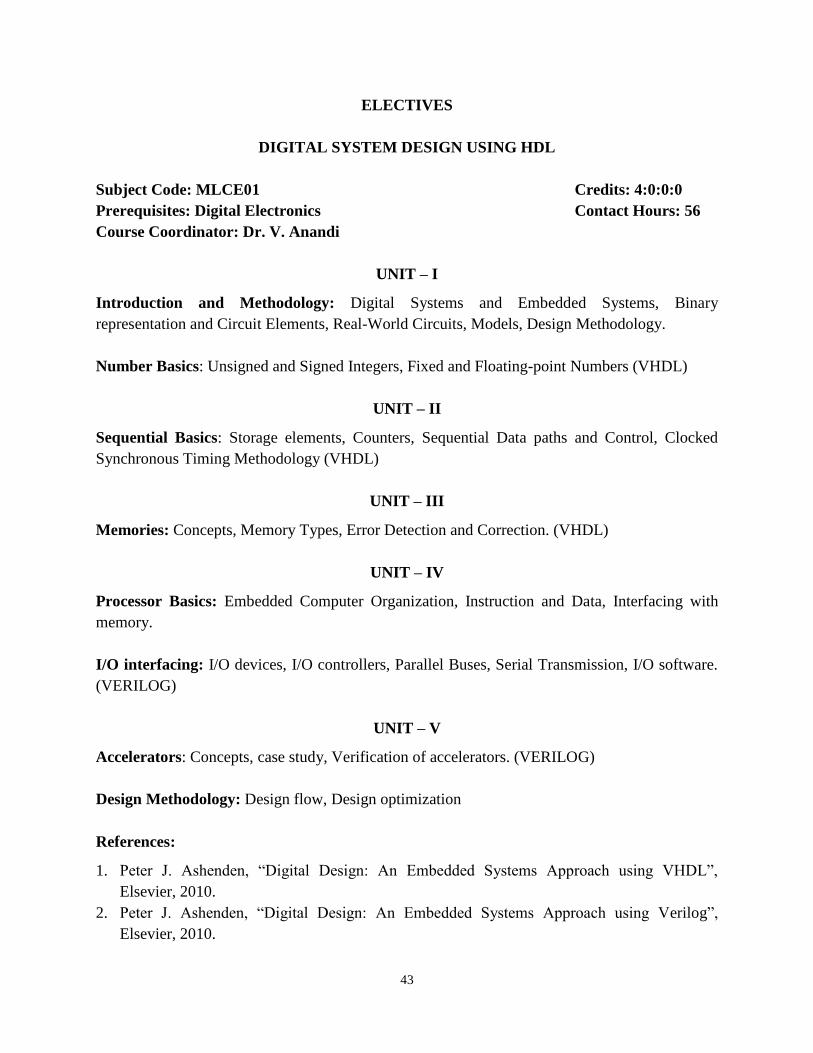
DIGITAL SYSTEM DESIGN USING HDL
Subject Code: MLCE01 Credits: 4:0:0:0
Prerequisites: Digital Electronics Contact Hours: 56
Course Coordinator: Dr. V. Anandi
UNIT – I
Introduction and Methodology: Digital Systems and Embedded Systems, Binary
representation and Circuit Elements, Real-World Circuits, Models, Design Methodology.
Number Basics: Unsigned and Signed Integers, Fixed and Floating-point Numbers (VHDL)
UNIT – II
Sequential Basics: Storage elements, Counters, Sequential Data paths and Control, Clocked
Synchronous Timing Methodology (VHDL)
UNIT – III
Memories: Concepts, Memory Types, Error Detection and Correction. (VHDL)
UNIT – IV
Processor Basics: Embedded Computer Organization, Instruction and Data, Interfacing with
memory.
I/O interfacing: I/O devices, I/O controllers, Parallel Buses, Serial Transmission, I/O software.
(VERILOG)
UNIT – V
Accelerators: Concepts, case study, Verification of accelerators. (VERILOG)
Design Methodology: Design flow, Design optimization
References:
1. Peter J. Ashenden, “Digital Design: An Embedded Systems Approach using VHDL”,
Elsevier, 2010.
2. Peter J. Ashenden, “Digital Design: An Embedded Systems Approach using Verilog”,
Elsevier, 2010.

44
3. William I. Fletcher, “An Engineering Approach to Digital Design”, PHI, 1990.
4. John Wakerley, “Digital System Design”, Prentice Hall International, 2000.
5. M Ciletti, “Advanced Digital Design with Verilog HDL”, Indian reprint, PHI, 2012.
Course Outcomes:
1. Employ the design approach based on programmable logic for system design. (POs: 1, 4)
2. Apply the basic principles of logic design and the basic concepts of HDL for their design.
(POs: 3, 4)
3. Demonstrate the use of HDLs for modeling combinational and sequential data path and
control circuits. (POs: 3, 4)
4. Employ the concepts of embedded processors like microcontrollers for designing new
systems. (POs: 1, 4)
5. Identify the peripherals suitable for their design and interface them for their designs.
(POs: 1, 4)

45
DESIGN OF ELECTRONIC SYSTEMS
Subject Code: MLCE02 Credits: 3:0:0:1
Prerequisites: Electronic Circuits Contact Hours: 42
Course Coordinator: Ms. Akkamahadevi M B
UNIT – I
Overview of Design of Electronic Systems: Evolution and importance of design of electronics
system, Impact of global competition & innovation on system design, Broad classification of
systems as consumer, professional, aerospace & defense: salient differences.
UNIT – II
Transmission Lines and Antennas: Optimizing the selection process in system design of
coaxial, planar and wave guides, with respect to impedance, frequency of operation, transmission
efficiency, Impact of transmission line power handling capacity and VSWR on system cost,
System design consideration for selection of antennas in terms of its performance parameters,
Design considerations for antenna for mobile handheld device.
UNIT – III
Packaging & Interconnection Technology: Introduction & overview of microelectronics
packaging & its influence on system performance & cost, Packaging hierarchy, Driving force on
packaging technology. Overview of MIC: thick and thin film circuits, MCM definition &
classification, their advantages in systems.
UNIT – IV
PCB Technologies: Importance of PCB laminates in electronic systems, Classification of
laminates and their construction details, Processes of selection of PCB laminate in electronic
systems, System design consideration in PCB fabrication, Photolithographic technique,
multilayer laminates and their salient features affecting systems.
UNIT – V
Case Studies on Electronic System Design: Defence Radar: Overview of system
consideration during the design of Radar, Introduction to Integration of Radar Pulses, Radar
cross section of Targets, Transmitter Power, Pulse Repetition Frequency, system losses,
Probabilities of Detection & False alarm, Typical hardware and software details.
Self-Study: Different standards for mobile data and communication, Satellite communication,
sensor interfacing standards, Calibration of electronic equipment, Various Standards and their

46
importance: ISO, ISI, JSS, Overview and classification of transmission lines, MMICs,
importance of MMICs in electronic system, Introduction to Radar
References:
1. Merrill. I. Skolnik, “Introduction to Radar Systems”, 3rd
Edition, Tata McGraw Hill, 2001.
2. Rao R Tum Mala, “Fundamentals of Microsystems Packaging”, McGraw Hill, NY 2001.
3. William D Brown, “Advanced Electronic Packaging”, IEEE Press, 1999.
4. David M. Pozar “Microwave Engineering”, 3rd
Edition, Wiley-India, 2009.
5. W.C. Bosshart, “Printed Circuit Boards: Design and Technology”, Tata McGraw Hill, 1983.
Course Outcomes:
1. Demonstrate the process of translating user requirement to implementable steps meeting
global competition (POs: 1, 3, 4)
2. Select appropriate transmission lines and antennas for various system applications
(POs: 1, 3, 4)
3. Design appropriate packaging hierarchy for system design from chip, MCM, thick and thin
film circuits, MICs (POs: 1, 3, 4)
4. Select PCB laminates like glass epoxy, polyamide, etc. for system applications
(POs: 1, 3, 4)
5. Calculate important radar parameters for defence radar for detecting a military target
(POs: 1, 3, 4)
47
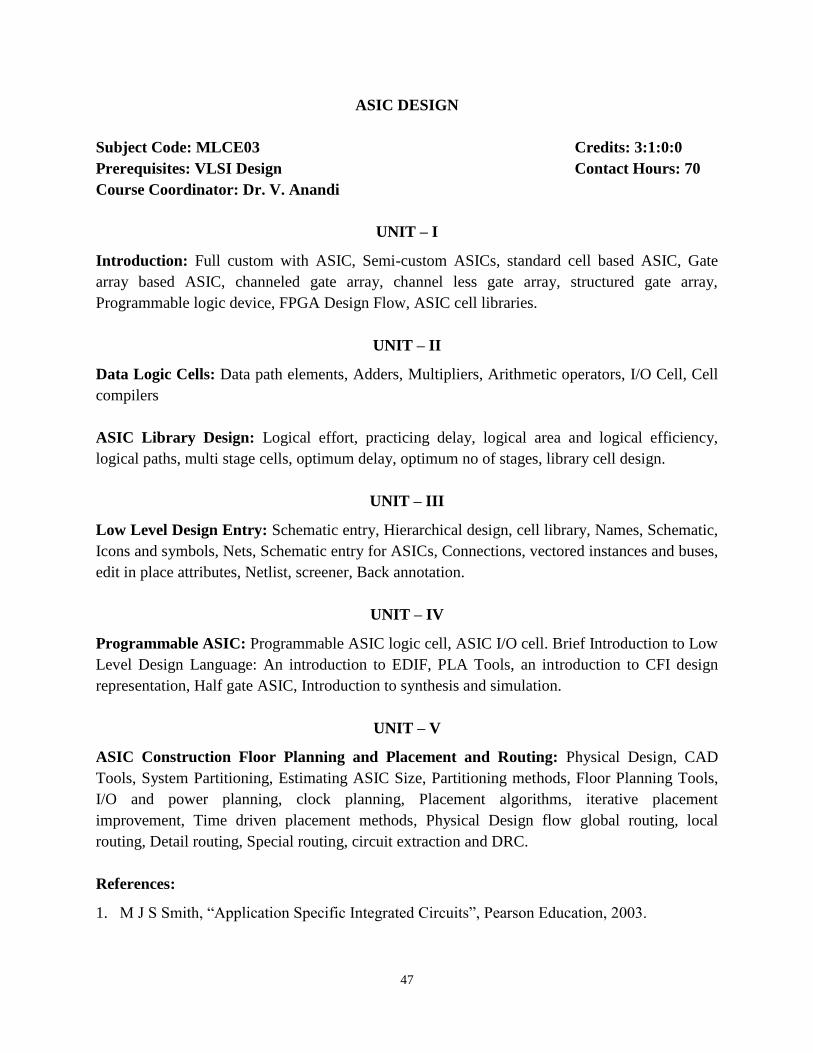
ASIC DESIGN
Subject Code: MLCE03 Credits: 3:1:0:0
Prerequisites: VLSI Design Contact Hours: 70
Course Coordinator: Dr. V. Anandi
UNIT – I
Introduction: Full custom with ASIC, Semi-custom ASICs, standard cell based ASIC, Gate
array based ASIC, channeled gate array, channel less gate array, structured gate array,
Programmable logic device, FPGA Design Flow, ASIC cell libraries.
UNIT – II
Data Logic Cells: Data path elements, Adders, Multipliers, Arithmetic operators, I/O Cell, Cell
compilers
ASIC Library Design: Logical effort, practicing delay, logical area and logical efficiency,
logical paths, multi stage cells, optimum delay, optimum no of stages, library cell design.
UNIT – III
Low Level Design Entry: Schematic entry, Hierarchical design, cell library, Names, Schematic,
Icons and symbols, Nets, Schematic entry for ASICs, Connections, vectored instances and buses,
edit in place attributes, Netlist, screener, Back annotation.
UNIT – IV
Programmable ASIC: Programmable ASIC logic cell, ASIC I/O cell. Brief Introduction to Low
Level Design Language: An introduction to EDIF, PLA Tools, an introduction to CFI design
representation, Half gate ASIC, Introduction to synthesis and simulation.
UNIT – V
ASIC Construction Floor Planning and Placement and Routing: Physical Design, CAD
Tools, System Partitioning, Estimating ASIC Size, Partitioning methods, Floor Planning Tools,
I/O and power planning, clock planning, Placement algorithms, iterative placement
improvement, Time driven placement methods, Physical Design flow global routing, local
routing, Detail routing, Special routing, circuit extraction and DRC.
References:
1. M J S Smith, “Application Specific Integrated Circuits”, Pearson Education, 2003.
48
2. Neil H. E. Weste, David Harris, Ayan Banerjee, “CMOS VLSI Design: A Circuits and
Systems Perspective”, 3rd
Edition, Addison Wesley/ Pearson education, 2011.
3. Vikram Arkalgud Chandrasetty, “VLSI Design: A Practical Guide for FPGA and ASIC
Implementations”, Springer, 2011.
4. Rakesh Chadha, J. Bhasker, “An ASIC Low Power Primer: Analysis, Techniques and
Specification”, Springer Publications, January 2015
Course Outcomes:
1. Describe the concepts of ASIC design methodology, data path elements and FPGA
architectures. (PO: 4)
2. Design data path elements for ASIC cell libraries and compute optimum path delay (PO: 4)
3. Employ industry synthesis tools to achieve desired objectives. (POs: 1, 2, 3, 5)
4. Analyze the design of FPGAs and ASICs suitable for specific tasks, perform design entry
and explain the physical design flow. (POs: 1, 3, 4)
5. Create floor plan including partition and routing with the use of CAD algorithms. (PO: 4)

49
ADVANCED EMBEDDED SYSTEMS
Subject Code: MLCE04 Credits: 4:0:0:0
Prerequisites: Microcontrollers Contact Hours: 56
Course Coordinator: Mrs. Lakshmi Shrinivasan
UNIT – I
Introduction to Embedded System: Core of the embedded System, Memories, Communication
Interface, Sensors and Actuators
Typical Embedded System: Washing Machine – Application specific ES, Automotive
communication buses
Introduction to ARM Cortex–M Processors: Advantages of the Cortex M processors,
applications of the ARM Cortex –M processors, Resources for using ARM processors and ARM
microcontrollers.
Hardware Software Co-Design and Program Modeling: Fundamental issues in the H/W, S/W
Co-Design Computational models in the embedded design: Data Flow-Graph/Diagram (DFG)
Model, Control Data Flow Graph / Diagram (CDFG), State machine model with examples.
Sequential program model, concurrent/communicating process model, unified modeling
language (WML) UML building blocks, UML Tools, Hardware and Software trade-offs typical
embedded product design and development approach.
UNIT – II
Technical Overview: ARM Cortex – M4: Processor type, architecture, block diagram, memory
System, Interrupt and exception support, Instruction set: Cortex – M4 specific instructions, barrel
shifter, features of ARM Cortex – M4
Low Power and System Control Features: Low power features, using WFI and WFE
instructions in programming
Fault Exceptions and Fault Handling: Overview of faults Causes of faults, enabling fault
handlers, fault status registers and fault address registers.

50
UNIT – III
Architecture of ARM Cortex-M4: Introduction to the architecture, Programmer‟s model,
behavior of the application program status register (APSR), Memory system, Exceptions and
interrupts, system control block.
UNIT – IV
Real Time Operating System (RTOS) based Embedded System Design: Operating System
basics, Types of OS, Tasks, Process and Threads, Multiprocessing and Multitasking, Threads,
Processes and Scheduling: Putting them altogether, Task Communication, Device Drivers,
How to Choose an RTOS
UNIT – V
The Embedded System Development Environment: Embedded Firmware design and
development, the Integrated Development Environment (IDE), Types of files generated on
Cross-compilation, Disassembler/Decompiler, Simulators, Emulators and Debugging, Target
Hardware Debugging, Boundary Scan.
References:
1. Joseph Yiu, “The Definitive Guide to ARM Cortex – M3 and Cortex – M4 Processors”,
Elsevier Ltd., 2014.
2. Shibu. K. V, “Introduction to Embedded Systems”, Tata McGraw Hill Education Private
Ltd. 2009.
3. Rajkamal, “Embedded Systems, Architecture, Programming and Design”, Tata McGraw Hill
Education Pvt., Ltd., 2009
4. Frank Vahid, Tony Givargis, “Embedded System Design – A Unified Hardware/ Software
Introduction”, John Wiley & Sons, 2002
Course Outcomes:
1. Identify the basic building blocks and computational models in embedded systems.
(POs: 1, 3, 4)
2. Develop the programs using technical knowledge of ARM Cortex M4 for embedded system
firmware development. (POs: 1, 3, 4, 5)
3. Describe ARM Cortex M4 various architectural features and its importance. (POs: 1, 3, 4)
4. Select the RTOS for real time embedded system design. (POs: 1, 3, 4)
5. Interpret the importance of debugger tools for embedded system design and development.
(POs: 1, 3, 4)

51
OPTICAL COMMUNICATION AND NETWORKING
Subject Code: MLCE05 Credits: 3:0:0:1
Prerequisites: Optical Communication Contact Hours: 42
Course Coordinator: Mr. Shreedarshan K
UNIT – I
Introduction: Propagation of signals in optical fiber, different losses, nonlinear effects, solitons,
optical sources, detectors.
Optical Components: Couplers, isolators, circulators, multiplexers, filters, gratings,
interferometers, amplifiers.
UNIT – II
Modulation — Demodulation: Formats, ideal receivers, Practical detection receivers, Optical
preamplifier, Noise considerations, Bit error rates, Coherent detection.
UNIT – III
Transmission System Engineering: System model, power penalty, Transmitter, Receiver,
Different optical amplifiers, Dispersion.
Optical Networks: Client layers of optical layer, SONET/SDH, multiplexing, layers, frame
structure, ATM functions, adaptation layers, Quality of service and flow control, ESCON,
HIPPI.
UNIT – IV
WDM Network Elements: Optical line terminal optical line amplifiers, optical cross
connectors, WDM network design, cost trade-offs, LTD and RWA problems, Routing and
wavelength assignment, wavelength conversion.
UNIT – V
Control and Management: Network management functions, management frame work,
Information model, management protocols, layers within optical layer performance and fault
management, impact of transparency.
Self-Study: Nonlinear effects, solitons, interferometers, amplifiers, Bit error rates, Coherent
detection, Quality of service and flow control, ESCON, HIPPI, Routing and wavelength
52
assignment, wavelength conversion, statistical dimensioning model, BER measurement, optical
trace, Alarm management, configuration management.
References:
1. Rajiv Ramswami, N Sivaranjan, “Optical Networks”, 3rd
Edition, M. Kauffman Publishers,
2009.
2. John M. Senior, “Optical Fiber Communications: Principles and Practice”, 3rd
Edition,
Pearson Education India, 2010.
3. Gerd Keiser, “Optical Fiber Communication”, 5th
Edition, MGH, 2017.
4. P.E. Green, “Optical Networks”, Prentice Hall, 1994.
Course Outcomes:
1. Identify the main parameters optical fiber, and the performance of optical communication
systems (POs: 1, 3, 4)
2. Analyze the equations that explain the modulation of an optical carrier and the various
parameters of an optical transmitter and receiver (POs: 1, 3, 4)
3. Identify the different types of networking configurations that may be used in an optical
network and analyze how component selection effects network design (POs: 1, 3, 4)
4. Design basic optical communication systems and analyze how its performance would be
affected by the various components used in the system design. (POs: 1, 2, 3, 4)
5. Implement a wavelength division multiplexed systems and formulate how altering the
parameters of the components used would change system capacity. (POs: 1, 2, 3, 4)
53
DATA COMPRESSION
Subject Code: MLCE06 Credits: 3:0:0:1
Prerequisites: Information Theory and Coding Contact Hours: 56
Course Coordinator: Prof. Maya V. Karki
UNIT – I
Lossless Compression Techniques: Introduction to lossy and lossless compression, Uniquely
Decodable codes, Prefix codes, Kraft McMillan Inequality, Huffman coding, Adaptive
Huffman coding, Arithmetic coding, Adaptive Dictionary (LZW) algorithm, Context based
compression (The Burrow Wheeler Transform ), Applications of lossless compression: text and
images.
UNIT – II
Lossy Compression Techniques: Basics of lossless compression, scalar quantization: uniform,
non-uniform and entropy coded quantization. Vector quantization: LBG algorithm, Tree
structured VQ, Structured VQ, Differential encoding: Prediction in DPCM, Adaptive DPCM,
Delta Modulation.
UNIT – III
Transform Coding: Transforms – KLT, DCT, DST, DWHT, Quantization and coding of
transform coefficients. Wavelets: multi resolution analysis and scaling, embedded zero tree
coder, set partitioning in hierarchical trees.
UNIT – IV
Image and Audio Compression Standards: JPEG standard, JPEG 2000 standard, ADPCM in
speech coding, G.726 ADPCM, Linear predictive coding, CELP. MPEG audio compression
UNIT – V
Video Compression Techniques: Video compression based on motion compensation, search for
motion vectors, H.261, H.263, MPEG – 1 and MPEG – 2 video coding
Self-Study: Context based compression (The Burrow Wheeler Transform), entropy coded
quantization, Tree structured VQ, Structured VQ, Delta Modulation, DWHT, ADPCM in speech
coding, H.263, MPEG-4, MPEG-7
References:
1. K. Sayood, “Introduction to Data Compression”, 3rd
Edition, Harcourt India Pvt. Ltd. &
Morgan Kaufmann Publishers,2006.

54
2. Z. Li and M.S. Drew, “Fundamentals of Multimedia,” Pearson Education (Asia) Pvt. Ltd.,
2004.
3. D. Salomon, “Data Compression: The Complete Reference,” Springer, 2000.
4. N. Jayant and P. Noll, “Digital Coding of Waveforms: Principles and Applications to Speech
and Video,” Prentice Hall, USA, 1984.
Course Outcomes:
1. Describe coding and decoding text message using Huffman, arithmetic and dictionary based
methods (POs: 3, 4)
2. Differentiate between scalar and vector quantizer and predictive coding. (POs: 1, 3, 4)
3. Apply DCT, DWT, EZW, and SPIHT compression algorithms for images. (POs: 1, 3, 4)
4. Illustrate JPEG, JPEG 2000, CELP and MPEG-1 audio standards. (POs: 1, 3, 4)
5. Differentiate different video standards. (POs: 1, 3, 4)

55
AUTOMOTIVE ELECTRONICS
Subject Code: MLCE07 Credits: 3:0:0:1
Prerequisites: Microcontrollers Contact Hours: 42
Course Coordinator: Mrs. Flory Francis
UNIT – I
Automotive Fundamentals Overview – Four stroke cycle, Engine control, Ignition system,
Spark plug, Spark pulse generation, Ignition timing, Drive train, Transmission, Brakes steering
system, Battery, Starting system, Air/Fuel system - Fuel handling, Air intake system, Air/Fuel
management.
UNIT – II
Sensors: Oxygen (O2/EGO) sensors, Throttle position sensor (TPS), Engine crankshaft angular
position (CKP) sensor, Magnetic reluctance position sensor, Engine speed sensor, Ignition timing
sensor, Hall effect position sensor, ShiECSedfiECS sensor, Optical crankshaft position sensor,
Manifold absolute pressure (MAP) sensor - Strain gauge and capacitor capsule, Engine coolant
temperature (ECT) sensor, Intake air temperature (IAT) sensor, Knock sensor, Airflow rate
sensor, Throttle angle sensor.
UNIT – III
Actuators: Fuel meeting actuator, Fuel injector, Ignition actuator. Exhaust after treatment
systems: Air, Catalytic converter, Exhaust gas recirculation (EGR), Evaporative emission
systems. Electronic engine control: Engine parameters, Variables, Engine performance terms,
Electronic fuel control systems, Electronic ignition controls, Idle speed control, EGR control.
UNIT – IV
Communication: Serial data, Communication systems, Protection, Body and chassis electrical
systems, Remote keyless entry, GPS.
Vehicle Motion Control: Cruise control, Chassis, Power brakes, Antilock brake systems,
(ABS), Electronic steering control, Power steering, Traction control, Electronically controlled
suspension.
Automotive Instrumentation: Sampling, Measurement and signal conversion of various
parameters.

56
UNIT – V
Integrated Body: Climate control systems, Electronic HVAC systems, Safety systems - SIR,
Interior safety, lighting, Entertainment systems.
Automotive Diagnostics: Timing light, Engine analyser, On-board diagnostics, off-board
diagnostics, Expert systems.
Future Automotive Electronic Systems: Alternative fuel engines, Collision avoidance radar
warning systems, Low tire pressure warning system, Navigation, advanced driver information
system.
Self-Study: Air/Fuel system fuel handling, air intake system, air/fuel management, knock
sensor, airflow rate sensor, throttle angle sensor, fuel meeting actuator, fuel injector, ignition
actuator, protection, remote keyless entry, traction control, safety systems, interior safety,
lighting, entertainment systems, alternative fuel engines.
References:
1. William B. Ribbens, “Understanding Automotive Electronics”, 6th
Edition, SAMS/Elsevier
Publishing, 2003.
2. Robert Bosch Gmbh, “Automotive Electrics, Automotive Electronics Systems and
Components”, 5th
Edition, John Wiley and Sons Ltd., 2007.
Course Outcomes:
1. Explain the automotive fundamentals and systems (PO: 3)
2. Identify and select sensors and actuators for different applications (PO: 1)
3. Analyze exhaust after-treatment systems, engine control systems and ignition control systems
using electronics (PO: 3)
4. Apply knowledge of electronics in vehicle motion control systems and automotive
instrumentation (POs: 1, 3)
5. Describe automotive diagnostics and future automotive electronic systems (PO: 1)
57
NANOELECTRONICS
Subject Code: MLCE08 Credits: 4:0:0:0
Prerequisites: Analog Electronics Contact Hours: 56
Course Coordinator: Mrs. A. R. Priyarenjini
UNIT – I
Introduction to Nanotechnology and Fabrication of Nanostructures: Overview of nano
science and engineering, Classification of Nanostructures, Electronic properties of atoms and
solids: Isolated atom, Bonding between atoms, Giant molecular solids, Free electron models and
energy bands, crystalline solids, Periodicity of crystal lattices, Electronic conduction, effects of
nanometer length, Effects of the nanometer length scale on electronic, magnetic, optical and
mechanical properties, Fabrication methods, Top down and Bottom up processes, Milling,
lithography, CVD, MBE, MOVPE, Colloidal methods, Self-assembly and self-organization.
UNIT – II
Characterization Methodology for Nanostructures: Characterization methods, Electron
microscopy, SEM and TEM, Scanning probe techniques, STM and AFM, Optical measurements,
Photoluminescence, cathode luminescence, Different methods for surface analysis and depth
profiling, Techniques for measurement of mechanical properties, electron transport properties,
magnetic and thermal properties.
UNIT – III
Semiconductor Nanostructures: Quantum confinement in semiconductor nanostructures,
quantum wells, quantum wires, quantum dots, super lattices, Band offsets, Electronic density of
states in 3D,2D and 1D systems, Requirements for semiconductor nanostructures, Epitaxial
growth of quantum wells, strain induced dots and wires, Modulation doping, quantum Hall
effect, Resonant tunneling.
UNIT – IV
Applications of Semiconductor Nanostructures: Applications of semiconductor
nanostructures, injection lasers, quantum cascade lasers, QWIPs – biological tagging, optical
memories, Coulomb blockade, single electron transistors, photonic structures, impact of
nanotechnology on conventional electronics.
UNIT – V
Nanomagnetic Materials and Devices: Classification, magneto resistance, Giant magneto
resistance, tunneling magneto resistance, applications, spin valves, magnetic tunnel junctions,

58
magnetic force microscope, Qubits, elements of quantum information theory, quantum cellular
automata.
References:
1. Robert W Kelsall, “Nanoscale Science and Technology”, 1st Edition, John Wiley, 2005.
2. Charles P. Poole Jr. and Frank J Owens, “Introduction to Nanotechnology”, Wiley
Inter science, 2003.
3. William Goddard III, “Handbook of Nano science, Engineering and Technology”, 1st
Edition, CRC Press, 2003.
Course Outcomes:
1. Describe nanostructures and the effect of scaling at nano scale (POs: 3, 4)
2. Explain basics of fabrication and characterization techniques in nano scale (POs: 3, 4)
3. Describe the semiconductor nano structures like quantum wells, wires and dots and their
fabrication methods and learn the concept of excitons (POs: 3, 4)
4. Explain the concepts of Quantum Hall effect and quantization of resistance (POs: 3, 4)
5. Categorize the various applications of nano materials and devices. (POs: 3, 4)

59
CMOS VLSI DESIGN
Subject Code: MLCE09 Credits: 4:0:0:0
Prerequisites: Physics of Semiconductor Devices Contact Hours: 56
Course Coordinator: Dr. M. Nagabhushan
UNIT – I
MOS Transistor Theory: n MOS / p MOS transistor, threshold voltage equation, body effect,
MOS device design equation, sub threshold region, Channel length modulation. mobility
variation, Tunneling, punch through, hot electron effect MOS models, small signal AC
Characteristics, CMOS inverter, βn / βp ratio, noise margin, static load MOS inverters,
differential inverter, transmission gate, tristate inverter, BiCMOS inverter.
UNIT – II
CMOS Process Technology: Lambda based Design rules, scaling factor, semiconductor
Technology overview, basic CMOS technology, p well / n well / twin well process. Current
CMOS enhancement (oxide isolation, LDD. refractory gate, multilayer inter connect), Circuit
elements, resistor, capacitor, interconnects, sheet resistance & standard unit capacitance concepts
delay unit time, inverter delays, driving capacitive loads, propagate delays, MOS mask layer,
stick diagram, design rules and layout, symbolic diagram, mask feints, scaling of MOS circuits.
UNIT – III
Basics of Digital CMOS Design: Combinational MOS Logic circuits: Introduction, CMOS
logic circuits with a MOS load, CMOS logic circuits, complex logic circuits, Transmission Gate.
Sequential MOS logic Circuits: Introduction, Behavior of bi stable elements, SR latch Circuit,
clocked latch and Flip Flop Circuits, CMOS D latch and triggered Flip Flop. Dynamic Logic
Circuits: Introduction, principles of pass transistor circuits, Voltage boot strapping synchronous
dynamic circuit techniques, Dynamic CMOS circuit techniques.
UNIT – IV
Dynamic CMOS and Clocking: Introduction, advantages of CMOS over NMOS, CMOS SOS
technology, CMOS bulk technology, latch up in bulk CMOS, static CMOS design, Domino
CMOS structure and design, Charge sharing, Clocking- clock generation, clock distribution,
clocked storage elements.
UNIT – V
Circuit Simulation: Introduction, Spice tutorials, Device models, Device characterization,
circuit characterization, Simulation mismatches, Monte carlo simulation
60
References:
1. Neil Weste and K. Eshragian, “Principles of CMOS VLSI Design: A System Perspective,”
2nd
Edition, Pearson Education (Asia) Pvt. Ltd., 2000.
2. David A Hodges, Horace G Jackson and Resve A Saleh “Analysis and Design of Digital
Integrated Circuits in Deep Sub-micron Technology”, 3rd
Edition, McGraw Hill, 2004.
3. Jan M Rabaey, Anantha Chandrakasan and Borivoje Nikolic, “Digital Integrated Circuits: A
Design Perspective”, 2nd
Edition, Pearson Education, 2004.
4. Sung Mo Kang and Yosuf Leblebici, “CMOS Digital Integrated Circuits: Analysis and
Design”, 3rd
Edition, McGraw-Hill, 2003.
Course Outcomes:
1. Understand the structure of MOS and its electrical behavior and solve simple problems
involving MOS device design equations (POs: 1, 3, 4)
2. Understand the MOS fabrication process including oxidation, ion implantations, and
problems in current CMOS fabrication process and suggest remedies (POs: 1, 3, 4)
3. Plan the CMOS layout of basic combinational and sequential logic blocks using appropriate
design rules and verify the schematic of a given CMOS circuit with its layout (POs: 3, 4)
4. Design CMOS circuits for a given digital logic circuit including Adder, Multipliers, Latches
and registers with logic structures including Domino logic and Clocked CMOS logic
(POs: 1, 3, 4)
5. Analyze a given CMOS circuit for its timing characteristics, to calculate and simulate for its
switching characteristics including rise time, fall time, its delay characteristics including
propagation delay, inertial delay, its setup and hold time (POs: 3, 4)

61
SIMULATION, MODELING AND ANALYSIS
Subject Code: MLCE10 Credits: 4:0:0:0
Prerequisites: Engineering Mathematics Contact Hours: 56
Course Coordinator: Mr. S. L. Gangadharaiah
UNIT – I
Basic Simulation Modeling: Nature of simulation, System models, discrete event simulation,
Single server simulation, Alternative approaches, Other types of simulation.
UNIT– II
Building Valid, Credible and Detailed Simulation Models: Techniques for increasing model
validity and credibility, comparing real world observations.
UNIT – III
Selecting Input Probability Distributions: Useful probability distributions, Assessing sample
independence, Activity – I, II and III, Model of arrival process.
UNIT – IV
Random Number Generators: Linear congruential, Other kinds, Testing number generators,
Random variate generation: Approaches, Continuous random variates, discrete random variates,
Correlated random variates.
UNIT – V
Output Data Analysis: Statistical analysis for term initiating simulation, Analysis for steady
state parameters, Comparing alternative system configuration, Confidence interval, Variance
reduction techniques, Arithmetic and control variates.
References:
1. Averill Law, “Simulation modeling and analysis”, 4th
Edition, McGraw Hill, 2007.
2. Jerry Banks, “Discrete event system simulation”, Pearson Education, 2009.
3. Seila Ceric and Tadikamalla, “Applied simulation modeling”, Cengage Publishing, 2009.
4. George. S. Fishman, “Discrete event simulation”, Springer, 2001.
5. Frank L. Severance, “System modeling and simulation”, Wiley, 2009.
Course Outcomes:
1. Describe the basic concepts in modeling and simulation (POs: 1, 3)
2. Classify various simulation models and give practical examples for each category (POs: 3, 4)

62
3. Construct a model for a given set of data and motivate its validity (POs: 1, 3)
4. Generate and test random number variates and apply them to develop simulation models
(POs: 1, 2, 3)
5. Analyze the output data produced by a model and test validity of the model (POs: 1, 2, 3, 4)

63
BROADBAND WIRELESS NETWORKS
Subject Code: MLCE11 Credits: 4:0:0:0
Prerequisites: Wireless Communication Contact Hours: 56
Course Coordinator: Dr. T. D. Senthilkumar
UNIT – I
WiMAX Genesis and Framework: IEEE 802.16 Standard From 802.16-2004 to 802.16e,
WiMAX Forum, WiMAX Forum Working Groups,WiMAX Forum White Papers, WiMAX
Products Certification,WiMAX Certified Products, Predicted Products and Deployment
Evolution, Product Types, Products and Deployment Timetable, Other 802.16 Standards, The
Korean Cousin: WiBro
Protocol Layers & Topologies –The Protocol Layers of WiMAX Convergence Sub layer
(CS),Medium Access Control Common Part Sub layer (MAC CPS), Security Sub layer, Physical
Layer, Single Carrier (SC) and OFDM, Network Management Reference Model, WiMAX
Topologies.
UNIT – II
Frequency Utilization and System Profiles: The Cellular Concept, Sectorisation, Cluster Size
Considerations, Handover, WiMAX System Profiles
WiMAX Physical Layer: OFDM Transmission, Basic Principle: Use the IFFT Operator, Time
Domain & Frequency Domain OFDM Considerations, OFDM Symbol Parameters and Some
Simple Computations , Physical Slot (PS) , Peak-to-Average Power Ratio (PAPR) , OFDMA and
Its Variants, Subcarrier Permutations in WiMAX OFDMA PHY.802.16 transmission chains.
UNIT – III
WiMAX MAC and QoS: CS layer, MAC function and frames, Introduction, MAC Addresses
and MAC Frames, MAC Header Format, MAC Sub-headers and Special Payloads,
Fragmentation, Packing and Concatenation, Basic, Primary and Secondary Management
Connections, User Data and MAC Management Messages, TLV Encoding in the 802.16
Standard, TLV Encoding Sets, Automatic Repeat Request (ARQ), ARQ Feedback Format,
Hybrid Automatic Repeat Request (HARQ) mechanism, Scheduling and Link Adaptation
UNIT – IV
Multiple Access and Burst Profile: Duplexing – FDD, TDD Mode, Transmission of Downlink
and Uplink Sub frames, OFDM PHY Downlink Sub frame, OFDM PHY Uplink Sub frame,
OFDMA PHY Frame, Frame Duration, Preambles, Maps of Multiple Access: DL-MAP and UL-

64
MAP, DL-MAP Message, UL-MAP Message, OFDMA PHY UL-MAP and DL-MAP Messages,
Burst Profile Usage: DCD Message and the DIUC Indicator, Burst Profile Selection Thresholds,
DCD (Downlink Channel Descriptor) Message, Transmission of the DCD Message, An Example
of the DCD Message, DIUC Values, UCD (Uplink Channel Descriptor) Message and UIUC
Indicator, Mesh Frame, Network Control Sub frame, Schedule Control Sub frame.
Uplink Bandwidth Allocation and Request Mechanisms: Types of Uplink Access Grant-
request, Uplink Access Grant-request mechanisms, Contention-based Focused Bandwidth
Request in OFDM PHY
UNIT – V
Radio Resource Management: Radio Engineering Consideration for WiMAX systems, Radio
Resource Management Procedures, Advanced Antenna Technologies in WiMAX, Multicast
Broadcast Services (MBS), Multi-BS Access MBS, MBS Frame.
WiMAX Architecture: Need for a Standardized WiMAX, High-level Architecture
requirements, Network Reference Model, Network Functionalities
References:
1. Loutfi Nuyami, “WiMAX – Technology for broadband access”, John Wiley, 2007.
2. Yan Zhang, Hsia-Hwa Chen, “Mobile WiMAX”, Aurobech Publications, 2008.
Course Outcomes:
1. Identify the different protocols and topologies in wireless networks. (POs: 1, 2, 3, 5)
2. Discuss the basics of cellular concepts and physical layer specifications of WiMAX.
(POs: 1, 2, 3, 5)
3. Describe the MAC layer responsibilities and its frame format. (POs: 1, 2, 3, 5)
4. Employ the various multiple access techniques for efficient spectrum allocation and
utilization (POs: 1, 2, 3, 5)
5. Describe the functional blocks of WiMax architecture and RF resource management.
(POs: 1, 2, 3, 5)

65
SPREAD SPECTRUM COMMUNICATION
Subject Code: MLCE12 Credits: 4:0:0:0
Prerequisites: Digital Communication Contact Hours: 56
Course Coordinator: Dr. T. D. Senthilkumar
UNIT – I
Direct Sequence Systems: Definitions and concepts, Spreading sequences and waveforms,
systems with BPSK modulation, Quaternary systems, pulsed interference, De-spreading with
Bandpass Matched Filters, Rejection of Narrow-band Interference
UNIT – II
Frequency Hopping Systems: Concepts and Characteristics, Frequency Hopping with
Orthogonal FSK, Frequency Hopping with CPM and DPSK, Hybrid Systems, Codes for Partial
Band Interference, Frequency Synthesizers
UNIT – III
Fading and Diversity: Path Loss, Shadowing, and Fading, Time Selective Fading, Spatial
Diversity and Fading, Frequency selective fading, Channel Impulse Response, Diversity for
Fading Channels, Rake Demodulator, Diversity and Spread Spectrum, Multicarrier Direct-
Sequence Systems, MC-CDMA System, DS-CDMA System with Frequency Domain
Equalization
UNIT – IV
Code Division Multiple Access and Frequency Hopping Multiple Access: Spreading
Sequences for DS/CDMA- Systems with Random Spreading Sequences, Cellular Networks and
Power Control, Frequency hopping Multiple Access
UNIT– V
Detection of Spread Spectrum Signals: Multiuser detectors, Detection of Spread Spectrum
Signals, Detection of Direct Sequence Signals, Estimation of Noise Power, Detection of
Frequency hopping signals
References:
1. Don Torrieri, “Principles of Spread-Spectrum Communication Systems”, 2nd
Edition,
Springer Verlag, 2005.
2. Robert C. Dixion, “Spread Spectrum Systems with Commercial Applications”, 3rd
Edition,
John Wiley and Sons, 1994.

66
3. Andrew J. Viterbi, “Principles of Spread Spectrum Communication”, Addison Wesley
Publishing Company, 1995.
Course Outcomes:
1. Employ the spreading and de-spreading principle in direct sequence spread spectrum based
communication systems (POs: 1, 2, 3)
2. Describe the importance of frequency synthesizers in the generation of frequency hopped
signals (POs: 1, 2, 3)
3. Analyze the significance of rake receiver in combating the effect of multi-path fading in
CDMA systems (POs: 1, 2, 3)
4. Describe the importance of power control technique in CDMA system to solve the near-far
problems (POs: 1, 2, 3)
5. Employ the concepts of multiuser detection in demodulation of direct sequence spread
spectrum and frequency hopping signals (POs: 1, 2, 3)

67
RF MEMS
Subject Code: MLCE13 Credits: 3:0:0:1
Prerequisites: Microwave and VLSI Circuits Contact Hours: 42
Course Coordinator: Mrs. Lakshmi S
UNIT– I
Foundation of MEMS: Multi-disciplinary aspects, Application areas, Scaling Laws in
miniaturization, scaling in geometry, electrostatics, electromagnetic, electricity and heat transfer.
Transduction Principles in MEMS Sensors: Microsensors – thermal, radiation, mechanical,
magnetic and bio-sensors, Actuators: Different actuation mechanisms - silicon capacitive
accelerometer, piezo-resistive pressure sensor, conductometric gas sensor, silicon micro-mirror
arrays, piezo-electric based inkjet print head, electrostatic comb-drive and magnetic micro relay,
portable clinical analyzer.
UNIT – II
Micromanufacturing and Material Processing: Silicon wafer processing, lithography, thin-
film deposition, etching (wet and dry), wafer-bonding, and metallization, Silicon
micromachining: surface, bulk, LIGA process.
UNIT – III
Electrical and Electronics Aspects: Electrostatics, Coupled Electro mechanics, stability and
Pull-in phenomenon, Practical signal conditioning Circuits for Microsystems.
Mechanical Concepts: Mechanical concepts, stress and strain, Flexural beam bending analysis
under Simple loading conditions analysis of beams under simple loading, Resonant frequency
and quality factor.
UNIT – IV
RF MEMS Switches and Micro – relays: Switch Parameters, Basics of Switching, Switches
for RF and microwave Applications, Actuation mechanisms, micro relays and micro actuators,
Dynamics of Switch operation, RF Design. MEMS Inductors and capacitors: Effect of inductor
layout, reduction of stray capacitance of planar inductors, approaches for improving quality
factor, Modeling and design issues of planar inductors. MEMS capacitor: gap tuning and area
tuning and dielectric tunable capacitors.
UNIT–V
Micromachined RF Filters and Phase Shifters: RF Filters, Modeling of Mechanical Filters,
Micromachanical Filters, Micromachined Filters for Millimeter Wave frequencies,
Micromachined Phase Shifters, Types and Limitations, MEMS and Ferroelectric Phase shifters,
68
Applications, Micromachined antennas: Design, Fabrication and Measurements.
Self-Study: Active noise control, bonding based process flows, coupled domain concepts, RF
Design of switches and associated circuitry, approaches for improving quality factor of micro
machined inductors, SAW filters, Resonators and Filters, Reliability issues and thermal issues in
packaging micromachined devices.
References:
1. G. K. Ananthasuresh, K. J. Vinoy, S. Gopalakrishnan, K. N. Bhat, V. K. Aatre, “Micro and
Smart Systems”, Wiley India, 2010.
2. V K Varadan, K J Vinoy, K. A. Jose, ―RF MEMS”, John Wiley, 2003.
3. J De Los Santos, “RF MEMS Circuit Design”, Artech House, 2002
Course Outcomes:
1. Analyze the functionality of microsystems. (POs: 1, 3, 4)
2. Describe the various fabrication concepts of MEMs. (POs: 1, 3, 4)
3. Describe the electrical and electronics concepts of microsystems. (POs: 1, 3, 4)
4. Design RF MEMS switches, inductors and capacitors. (POs: 1, 3, 4)
5. Analyze the operation of RF MEMS filters and phase shifter. (POs: 1, 3, 4)

69
PATTERN RECOGNITION AND ANALYSIS
Subject Code: MLCE14 Credits: 3:0:0:1
Prerequisites: Signal Processing Contact Hours: 42
Course Coordinator: Prof. K. Indira
UNIT – I
Introduction to Probability and Decision Theory: Probability Theory: Probability densities,
Expectations and covariances, Bayesian probabilities, Gaussian distribution, Bayesian curve
fitting.
Decision Theory: Minimizing the misclassification rate, the expected loss, the reject option,
inference and decision, loss functions for regression.
UNIT – II
Probability Distributions: Binary variables, Multinomial Variables, Gaussian distribution:
Conditional and Marginal Gaussian distribution, Bayes‟ theorem for Gaussian variables,
Maximum likelihood for the Gaussian, Sequential estimation, Bayesian inference for the
Gaussian and Mixtures of Gaussians
Non-parametric Methods: Kernel density estimators and Nearest-neighbor methods.
UNIT – III
Linear Models for Classification: Discriminant functions: Two classes, multiple classes, Least
squares for classification, Fisher‟s linear discriminant, Relation to least squares, the Perceptron
algorithm.
Probabilistic Generative Models: Continuous inputs, Maximum likelihood solution, discrete
features and exponential family.
UNIT – IV
Neural Networks: Feed Forward Network functions: Weight Space Symmetries. Network
Training: Parameter optimization, Local quadratic approximation, use of gradient information,
gradient descent optimization.
Error Back Propagation: Evaluation of error function derivatives, a simple example,
Efficiency of backpropagation

70
UNIT – V
Linear Transformations and Dimensionality Reduction: Basis vectors and Images, Singular
Value Decomposition, Independent component analysis, Nonlinear Dimensionality Reduction,
Discrete Fourier transform, Template Matching: Measures based on Optimal Path Search,
Measures based on correlations, Deformable Template Models.
Self-Study: Probability Theory: Probability densities, Expectations and covariances, Bayes‟
theorem for Gaussian variables, Maximum likelihood for the Gaussian, Fisher‟s Linear
discriminant, Relation to least squares, A simple example of error back propagation, Efficiency
of back propagation, Basis vectors and images, Singular Value Decomposition.
References:
1. C Bishop, “Pattern Recognition and Machine Learning”, Springer, 2006.
2. S Theodoridis and K Koutroumbas, “Pattern Recognition”, 4th
Edition, Academic Press,
2009.
3. Richard O. Duda, Peter E. Hart, David G.Stork, “Pattern Classification”, 2nd
Edition,
JohnWiley, 2000.
4. Earl Gose, Richard Johnsonburg and Steve Joust, “Pattern Recognition and Image Analysis”,
Prentice Hall of India, 2003.
5. S Theodoridis and K Koutroumbas, “An Introduction to Pattern Recognition: A Matlab
Approach”, Elsevier Publications, 2010.
Course Outcomes:
1. Define probability densities and Bayes Theorem (POs: 3, 4)
2. Apply Bayes theorem for pattern classification (POs: 3, 4)
3. Define various classifiers (POs: 1, 3, 4)
4. Apply Neural Network for pattern classification (POs: 1, 3, 4)
5. Apply linear transformation for dimensionality reduction (POs: 1, 3, 4)
71
IMAGE AND VIDEO PROCESSING
Subject Code: MLCE15 Credits: 3:1:0:0
Prerequisites: Signal Processing Contact Hours: 42
Course Coordinator: Prof. K. Indira
UNIT – I
Introduction to 2D Systems: 2D systems, Mathematical preliminaries – Fourier Transform, Z
Transform, Optical & Modulation transfer function, Matrix theory, Random signals, Discrete
Random fields, Spectral density function, 2D sampling theory, Limitations in sampling &
reconstruction, Quantization, Optimal quantizer, Compander, Visual quantization.
UNIT – II
Image Transforms: Introduction, 2D orthogonal & unitary transforms, Properties of unitary
transforms, DFT, DCT, DST, Hadamard, Haar, Slant, KLT, SVD transform.
UNIT – III
Image Enhancement: Point operations, Histogram modeling, spatial operations, Transform
operations, Multi-spectral image enhancement, false color and Pseudo-color, Color Image
enhancement.
UNIT – IV
Image Filtering and Restoration: Image observation models, Inverse & Wiener filtering,
Fourier Domain filters, Smoothing splines and interpolation, Least squares filters, generalized
inverse, SVD and Iterative methods, Maximum entropy restoration, Bayesian methods,
Coordinate transformation & geometric correction, Blind de-convolution.
UNIT – V
Image Analysis, Computer Vision and Video Processing: Spatial feature extraction,
Transform features, Edge detection, Boundary Extraction, Boundary representation, Region
representation, Moment representation, Structure, Shape features, Texture, Scene matching
&detection, Image segmentation, Classification Techniques. Representation of Digital Video –
Analog and digital video, Models for time-varying images, time-space sampling, conversion
between sampling structures.
References:
1. A. K. Jain, “Fundamentals of Digital Image Processing", Pearson Education (Asia) Pvt. Ltd. /
Prentice Hall of India, 2004.

72
2. M. Sonka, V. Hlavac, R. Boyle, “Image Processing, Analysis and Machine Vision”, 3rd
Edition, Thomson – Brooks Cole, 1999.
3. Z. Li and M.S. Drew, “Fundamentals of Multimedia”, Pearson Education (Asia) Pvt Ltd.,
2004.
4. R. C. Gonzalez and R. E. Woods, “Digital Image Processing”, 3rd
Edition, Pearson Education
(Asia) Pvt. Ltd/Prentice Hall of India, 2009.
5. William K. Pratt, “Digital Image Processing”, Wiley Interscience, 2007.
6. M. Tekalp, “Digital Video Processing”, Prentice Hall, USA, 1995.
Course Outcomes:
1. Analyze the effect of sampling and quantization on an N x N image (POs: 3, 4)
2. Describe various unitary transforms.(POs: 1, 3, 4)
3. Design image enhancement technique using histogram modeling (POs: 1, 3, 4)
4. Evaluate the methodologies for image filtering and restoration.(POs: 1, 3, 4)
5. Apply image processing algorithms for segmentation, classification and digital video (POs:
1, 3, 4)
73
ADVANCED COMPUTER NETWORKS
Subject Code: MLCE16 Credits: 3:1:0:0
Prerequisites: Computer Communication Networks Contact Hours: 42
Course Coordinator: Mrs. Sarala S M
UNIT – I
Introduction: Computer network, Telephone networks, networking principles.
Multiple access: Multiplexing – FDM, TDM, SM.
UNIT – II
Local Area Networks: Ethernet, Token ring, FDDI
Switching - Circuit switching, Packet switching, Multicasting.
Scheduling: Performance bounds, Best effort disciplines, Naming and addressing, Protocol
stack, SONET, SDH.
UNIT – III
ATM Networks: AAL, Virtual circuits, SSCOP
Internet - Addressing, Routing, Endpoint control.
UNIT – IV
Internet Protocol: IP, TCP, UDP, ICMP, HTTP
Traffic Management: Models, Classes, Scheduling
UNIT – V
Control of Networks: QoS, Static and dynamic routing, Markov chains, Queuing models,
Bellman Ford and Dijkstra's algorithm, Window and rate congestion control, Large deviations of
a queue and network, Open and closed loop flow control, Control of ATM networks.
References:
1. J. Walrand and P. Varaya, “High Performance Communication Networks”, Harcourt Asia
(Morgan Kaufmann), 2000.
2. S. Keshav, “An Engineering Approach to Computer Networking”, Pearson Education, 1997.
3. A. Leon-Garcia and I. Widjaja, “Communication Networks: Fundamental Concepts and Key
Architectures”, TMH, 2000.
4. J. F. Kurose, and K. W. Ross, “Computer Networking: A Top Down Approach featuring the
Internet”, Pearson Education, 2001.

74
Course Outcomes:
1. Demonstrate knowledge of basic networking concepts and multiplexing (POs: 3, 4)
2. Explain the basic model of local area networks, switched networks and scheduling
(POs: 3, 4)
3. Appreciate the various concepts of ATM Networks and Internet (POs: 1, 3, 4)
4. Analyze different internet protocols and traffic management (POs: 1, 3, 4)
5. Discuss the control of networks (POs: 3, 4)

75
ADVANCES IN VLSI DESIGN
Subject Code: MLCE17 Credits: 4:0:0:0
Prerequisites: VLSI Design Contact Hours: 56
Course Coordinator: Mr. Manjunath C. Lakkannavar
UNIT – I
Review of MOS Circuits: MOS and CMOS static plots, switches, comparison between CMOS
and BI – CMOS, MESFETS: MESFET and MODFET operations, quantitative description of
MESFETS, MIS Structures and MOSFETS: MIS systems in equilibrium, under bias, small
signal operation of MESFETS and MOSFETS
UNIT– II
Short Channel Effects and Challenges to CMOS: Short channel effects, scaling theory,
processing challenges to further CMOS miniaturization Beyond CMOS: Evolutionary advances
beyond CMOS, carbon nano tubes, conventional vs. tactile computing, computing, molecular
and biological computing Mole electronics-molecular diode and diode- diode logic, Defect
tolerant computing.
UNIT – III
Super Buffers, Bi-CMOS and Steering Logic: Introduction, RC delay lines, super buffers- An
NMOS super buffer, tri state super buffer and pad drivers, CMOS super buffers, Dynamic ratio
less inverters, large capacitive loads, pass logic, designing of transistor logic, General functional
blocks - NMOS and CMOS functional blocks.
UNIT – IV
Special Circuit Layouts and Technology Mapping: Introduction, Talley circuits, NAND-
NAND, NOR- NOR, and AOI Logic, NMOS, CMOS Multiplexers, Barrel shifter, Wire routing
and module layout.
UNIT – V
System Design: CMOS design methods, structured design methods, Strategies encompassing
hierarchy, regularity, modularity & locality, CMOS Chip design Options, programmable logic,
Programmable inter connect, programmable structure, Gate arrays standard cell approach, Full
custom design.
76
References:
1. Kevin F Brenan “Introduction to Semiconductor Devices”, 1st Edition, Cambridge University
Press, 2005.
2. Eugene D Fabricius “Introduction to VLSI Design”, McGraw-Hill International Publication,
1990.
3. D. A. Pucknell, K. Eshraghian, “Basic VLSI Design”, PHI, 1995.
4. Wayne Wolf, “Modern VLSI Design”, 2nd
Edition, Pearson Education, 2002.
Course Outcomes:
1. Recall the fundamentals and operation of MESFET, MODFET, MIS structure and MOSFET
(POs: 1, 3, 4)
2. Design a digital circuit using CMOS logic such as Talley circuit, NAND-NAND, NOR-
NOR, AOI Logic (POs: 1, 3, 4)
3. Describe the concept of RC delay lines, super buffers, and large capacitive loads with respect
to CMOS VLSI (POs: 1, 3, 4)
4. Analyze performance issues and the inherent trade-offs involved in system design (i.e. power
vs. speed). (POs: 1, 3, 4)
5. Explain the concept of Carbon nanotubes, Molecular and Biological Computing, Defect
Tolerant Computing, and Programmable Logic (POs: 1, 3, 4)
77
ADVANCES IN RADAR SYSTEMS
Subject Code: MLCE18 Credits: 4:0:0:0
Prerequisites: Radar Contact Hours: 56
Course Coordinator: Ms. Akkamahadevi M B
UNIT – I
Introduction: Range equation, Transmitter and Receiver parameters, Model and types of
Radars.
UNIT – II
Radar Signal Transmission: Transmitted waveforms (time and frequency domains), Energy,
Radar signal analysis using autocorrelation and Hilbert transform, Pulse compression.
UNIT – III
Clutter: Properties, reduction, coding and chirp.
Radar Antennas: Reflector types, Sidelobe control, Arrays - Array factor and beamwidth,
Synthetic aperture, adaptive antennas.
Propagation effects: Multipath, Low altitude, Ionosphere.
UNIT – IV
Radar Networks: Matched filter response and noise consideration.
Data Processing: FFT, Digital MTI, Tracking, Plot track.
UNIT – V
Applications: Secondary surveillance, Bistatic, Multistatic, Over the Horizon, Remote sensing,
Meteorological radars and Millimeter-wave radars.
References:
1. Meril I. Skolnik, “Radar handbook”, 3rd
Edition, McGraw-Hill Education, 2008
2. M. J. B. Scanlan, “Modern Radar Techniques”, Macmillan Publishing, 1987.
3. Peyton Z. Peebles, “Radar Principles”, John Wiley & Sons Limited, 2002.

78
Course Outcomes:
1. Identify the main parameters of transmitter and receiver that influence the operation of radar.
(POs: 1, 3, 4)
2. Analyze the radar signals in terms of energy content, autocorrelation, Hilbert transform and
pulse compression techniques. (POs: 1, 3, 4)
3. Identify the different properties of clutter and propagation effects and methods to combat
them. (POs: 1, 3, 4)
4. Demonstrate different types of radar antennas and radar signal processing methods.
(POs: 1, 3, 4)
5. Discuss the applications of radar. (POs: 1, 3, 4)
79
COMMUNICATION SYSTEM DESGN USING DSP
Subject Code: MLCE19 Credits: 3:1:0:0
Prerequisites: Analog & Digital Communication Contact Hours: 42
Course Coordinator: Dr. T. D. Senthilkumar
UNIT – I
Introduction: Digital filters, Discrete time convolution and frequency responses, FIR filters -
Using circular buffers to implement FIR filters in C and using DSP hardware, Interfacing C and
assembly functions, Linear assembly code and the assembly optimizer. IIR filters - realization
and implementation, FFT and power spectrum estimation: DTFT window function, DFT and
IDFT, FFT, Using FFT to implement power spectrum.
UNIT – II
Analog Modulation Schemes: Amplitude Modulation - Theory, generation and demodulation of
AM, Spectrum of AM signal, Envelope detection and square law detection, Hilbert transform
and complex envelope, DSP implementation of amplitude modulation and demodulation.
DSBSC: Theory, generation of DSBSC, Demodulation, and demodulation using coherent
detection and Costas loop, Implementation of DSBSC using DSP hardware.
SSB: Theory, SSB modulators, Coherent demodulator, Frequency translation, Implementation
using DSP hardware.
UNIT – III
Frequency Modulation: Theory, Single tone FM, Narrow band FM, FM bandwidth, FM
demodulation, Discrimination and PLL methods, Implementation using DSP hardware.
UNIT – IV
Digital Modulation Schemes: PRBS, and data scramblers: Generation of PRBS, Self-
synchronizing data scramblers, Implementation of PRBS and data scramblers. RS-232C protocol
and BER tester: The protocol, error rate for binary signaling on the Gaussian noise channels,
Three bit error rate tester and implementation.
UNIT – V
PAM: PAM theory, baseband pulse shaping and ISI, Implementation of transmit filter and
interpolation filter bank. Simulation and theoretical exercises for PAM, Hardware exercises for
PAM.

80
QAM: Basic QAM transmitter, 2 constellation examples, QAM structures using passband
shaping filters, Ideal QAM demodulation, QAM experiment. QAM receivers - Clock recovery
and other frontend sub-systems, Equalizers and carrier recovery systems.
Experiment for QAM Receiver Frontend: Adaptive equalizer, Phase splitting, fractionally
spaced equalizer. Decision directed carrier tracking, Blind equalization, Complex cross coupled
equalizer and carrier tracking experiment, Echo cancellation for full duplex modems:
Multicarrier modulation, ADSL architecture, Components of simplified ADSL transmitter, a
simplified ADSL receiver, Implementing simple ADSL Transmitter and Receiver.
References:
1. Steven A. Tretter, “Communication System Design using DSP Algorithms with Laboratory
Experiments for the TMS320C6713DSK”, Springer, 2008.
2. Vinay Ingle, John Proakis, “Digital Signal Processing using MATLAB”, Cengage Learning,
2011.
3. John G. Proakis, Masoud Salehi, and Gerhard Bauch, “Contemporary Communication
Systems using MATLAB and Simulink”, 2nd
Edition, Thomson-Brooks/Cole, 2004.
Course Outcomes:
1. Employ C and assembly functions in the implementation of filters and Fourier transforms,
using DSP hardware (POs: 3, 4)
2. Apply amplitude modulation concepts in the DSP implementation of AM/DSB transceiver
(POs: 3, 4)
3. Demonstrate the DSP hardware implementation of frequency modulation scheme (POs: 3, 4)
4. Analyze the bit error rate performance of the binary modulation receiver (POs: 1, 3, 4)
5. Demonstrate the function of QAM transmitter and receiver hardware (POs: 1, 3, 4)

81
RF AND MICROWAVE CIRCUIT DESIGN
Subject Code: MLCE20 Credits: 4:0:0:0
Prerequisites: Microwave Circuits Contact Hours: 56
Course Coordinator: Mrs. Sujatha B
UNIT – I
Wave Propagation in Networks: Introduction, Reasons for using RF/Microwaves,
Applications, RF waves, RF and Microwave circuit design, Introduction to components basics,
Analysis of simple circuit phasor domain, RF impedance matching, Properties of waves,
transmission media, Micro strip lines, High frequency parameters, Formulation of S-parameters,
Properties, transmission matrix, Generalized S-parameters.
UNIT – II
Passive Circuit Design: Introduction, Smith chart, Scales, Application of Smith chart, Design of
matching networks, Definition of impedance matching, Matching using lumped and distributed
elements.
Basic Consideration in Active Networks and design of amplifiers, oscillators and detector:
Stability consideration, gain consideration, Noise consideration.
UNIT – III
Linear and Non-linear Design: Introduction, Types of amplifier, Design of different types of
amplifiers, Multi-stage small signal amplifiers,
Design of Transistor Oscillators: Oscillator versus Amplifier Design. Oscillation Conditions,
Design of Transistor Oscillators, Generator Tuning Networks.
UNIT – IV
RF/Microwave Frequency Conversion I: Rectifier and Detector Design: Detector losses,
Effect of Matching Network on the Voltage Sensitivity, detector design.
RF/Microwave Frequency Conversion II: Mixer Design: Mixers, Mixer types, Conversion
loss for SSB mixers, One-Diode (or Single-Ended) Mixers, Two-Diode Mixers, Four Diode
Mixers, Eight-Diode Mixers.
UNIT – V
RF/Microwave Control Circuit Design: Phase shifters, Digital phase shifters, Semiconductor
phase shifters, PIN Diode Attenuators

82
RF and microwave IC design, MICs, MIC materials, Types of MICs, Hybrid verses monolithic
MICs,
References:
1. Matthew M. Radmanesh, “RF and Microwave Electronics Illustrated”, Pearson Education,
2004.
2. Reinhold Ludwig, and Pavel Bretchko, “RF Circuit Design Theory and Applications”,
Pearson Education, 2004.
Course Outcomes:
1. Employ transmission line theory, S-parameters, and Smith chart for microwave circuit
analysis (POs: 3, 4)
2. Design passive microwave matching circuits (POs: 3, 4)
3. Design microwave amplifiers, oscillators, resonators and micro-strip circuits (POs: 3, 4)
4. Discuss features of active high-frequency matching networks, detector and mixer devices
(POs: 3, 4)
5. Design microwave ICs and hybrid ICs using MIC materials (POs: 3, 4)