current transformer testing
TRANSCRIPT

A METHOD FOR TESTING CURRENT TRANSFORMERS
By Francis B. Silsbee
CONTENTSt
Page
Introduction 317General principles 318
Null method 321
Deflection method 325Experimental results 3 28
Summary 328
INTRODUCTION
Several precise laboratory methods are now available for the
determination of the ratio and phase angle of current transformers. 1
These, however, all require a considerable amount of special
apparatus, such as carefully calibrated noninductive shunts andvery sensitive alternating-current detectors, and are therefore not
suited for use under shop or central-station conditions.
The task of comparing the constants of one transformer with
those of a second transformer taken as a standard is much less
difficult. The standard transformer should, of course, have the
same nominal ratio, and its constants should have been deter-
mined by one of the precise laboratory methods. A method for
such a comparison of two voltage transformers has been pub-
lished by Brooks, 2 and another method applicable to either
voltage or current transformers by Agnew 3 and by Knopp. 4
The method developed in this paper is somewhat analogous to
the first of these and will be found rather more rapid than the
second.
As in the other comparison methods the detector may be muchless sensitive than in the absolute methods, and it is therefore
1 Agnew and Fitch, this Bulletin, 6, p. 281, 1909; Electrical World, 54, p. 1042, 1909; E. Orlich, E. T. Z.,
30, p. 435, 466, 1909; E. T. Robinson, Trans. Am. Inst. Elec. Eng., 28, p. 1005, 1909; F. A. Laws, Electrical
World, 55, p. 223, 1910; Sharp and Crawford, Trans. Am. Inst. Elec. Eng., 29, p. 1517, 1910; Agnew andSilsbee, Trans. Am. Inst. Elec. Eng., 31, p. 1635, 1912; Schering and Alberti, Archiv fur Elcktroteclmik,
2, p. 263, 1914.
2 H. B. Brooks, this Bulletin, 10, p. 419, 1914 (Scientific Paper No. 217); Electrical World, 62, p. 898, 19x3.
3 P. G. Agnew, this Bulletin, 11, p. 347, 1914 (Scientific Paper No. 233).4 O. A. Knopp, Electrical World, 67, p. 92, 1916.
317

3i8 Bulletin of the Bureau of Standards [Vol. 14
possible to use a more rugged type of instrument, such as a com-
mercial wattmeter. Multiple-range transformers are particularly
useful as standards, since they show practically proportional
ratios and identical phase angles on the various primary con-
nections. Two or three such transformers, the ratio and phase
angle of which have been accurately determined, suffice for testing
a considerable range of transformers.
GENERAL PRINCIPLES
The principle of the method is illustrated by Fig. i . 5 and Xare the standard and the unknown transformer, respectively.
The primary windings are connected in series and supplied with
current from a suitable source. The secondary windings are also
Fig. i
connected in series, with such polarity that both tend to send
current in the same direction, and any desired impedance loads
such as zs and zx complete the circuit. A suitable detector D is
then connected so as to bridge across between the transformers.
It is evident that the current AI through the detector (which
we shall assume for the present to have a negligible impedance) is
necessarily equal to the vector difference of the secondary currents
Is and /x of the transformers. Consequently, if the magnitude
and phase of AI are measured, the difference in performance of
the two transformers can be computed. This measurement of
AI may be made either directly by using as a detector one
winding of a separately excited wattmeter, as is described below
as the "Deflection method," or the measurement may be madeindirectly by using an additional compensating circuit between
.4 and B, as indicated by the dotted lines. By proper arrange-
ment of the impedances all of AI may be made to flow in this
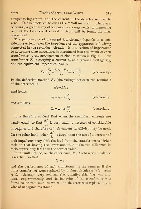
susbee] Testing Current Transformers 319
compensating circuit, and the current in the detector reduced to
zero. This is described below as the "Null method." There are,
of course, a great many other possible arrangements for measuringAI, but the two here described in detail will be found the mostconvenient.
The performance of a current transformer depends to a con-
siderable extent upon the impedance of the apparatus and wiring
connected in the secondary circuit. It is therefore of importance
to determine what impedance is introduced into the circuit of each
transformer by the arrangement of circuits shown in Fig. 1 . Nowtransformer X is carrying a current Ix at a terminal voltage Ex,
and the equivalent impedance load is
x = 7- = f= zx — j- (vectonally)
^x ^s ^x
In the deflection method Ed (the voltage between the terminals
of the detector) is
Ed = AIzd
And hence
and similarly
Zx = zx — zd-f— (vectorially)* X
Zs = zs + zd~y~ (vectorially)
It is therefore evident that when the secondary currents are
nearly equal, so that -y- is very small, a detector of considerable
impedance and therefore of high-current sensitivity may be used.
On the other hand, when -j— is large, then the use of a detector of
high impedance may shift the load from the transformer of higher
ratio to that having the lower and thus make the difference in
ratio appreciably less than the correct value.
In the null method, on the other hand, Ed is zero when a balance
is reached, so that7—9^X ^X
and the performance of each transformer is the same as if the
other transformer were replaced by a short-circuiting link across
A C. Although very evident theoretically, this fact was also
tested experimentally, and the behavior of the transformer was
found to be the same as when the detector was replaced by a
wire of negligible resistance.

320 Bulletin oj the Bureau oj Standards \Voi.i4
The principal limitation on the sensitivity attainable in anymethod of testing current transformers is due to the condition
that the measuring circuit must not affect the performance of the
transformer. This means that the measuring apparatus must not
increase the equivalent connected secondary load by more than a
certain resistance which we may denote by r.
The gain in sensitivity of a comparison method, such as is de-
scribed in this paper over an absolute method, is seen by comparing
the power available for operating the detector in the two cases.
In the usual absolute method the secondary current / is passed
through a noninductive resistance which is preferably equal to r.
The voltage drop Ir is balanced by the drop due to the primary
current flowing through a proportionately smaller resistance.
With such an arrangement the impedance of the circuit external
to the detector is approximately r, and for the maximum sensitivity
the detector itself should also have this same impedance. If under
these conditions the secondary current should differ by a small
amount 81 from that required for an exact balance, then the un-
balanced voltage acting in the detector circuit will be only blr.
Since the resistance of the complete circuit is 2r, the current flow-
big in the detector will be — , and the voltage across the detector
—2X T 5 T
will be — . Consequently the power available is —r.
On the other hand, in the case of the deflection method outlined
in this paper, the total difference AI between the two secondary
currents flows through the detector and produces a voltage at its
terminals equal to AIzd . Here zd is the impedance of the detector,
and is limited by the fact that this voltage AIzd must not exceed
the permissible value Ir for the largest value of A/. Conse-
quently, we have z&<iri Y and if we use a detector having this im-
pedance, the volt amperes available for a difference hi in the cur-
_2 /rents is 5/ ~Zjr. Since the two transformers will usually differ by
only a few per cent the factor -rj is fairly large and the detector
required may be 50 or 100 times less sensitive than in the precise
laboratory methods. It is this relation which brings the method
within the range of sensitivity obtainable with commercial pivoted
instruments.
susbee\ Testing Current Transformers 321
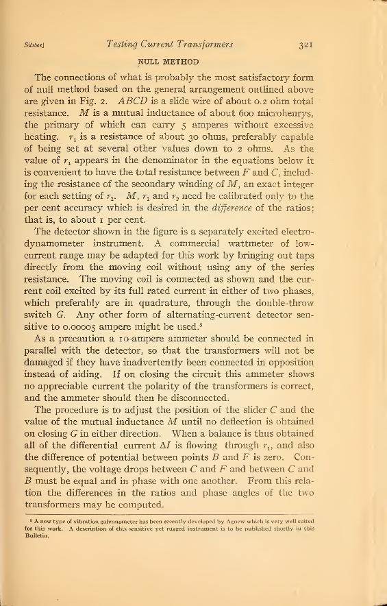
NULL METHOD
The connections of what is probably the most satisfactory form
of null method based on the general arrangement outlined above
are given in Fig. 2. ABCD is a slide wire of about 0.2 ohm total
resistance. M is a mutual inductance of about 600 microhenrys,
the primary of which can carry 5 amperes without excessive
heating. r± is a resistance of about 30 ohms, preferably capable
of being set at several other values down to 2 ohms. As the
value of rtappears in the denominator in the equations below it
is convenient to have the total resistance between F and C, includ-
ing the resistance of the secondary winding of M, an exact integer
for each setting of rv M, rtand r2 need be calibrated only to the
per cent accuracy which is desired in the difference of the ratios;
that is, to about 1 per cent.
The detector shown in the figure is a separately excited electro-
dynamometer instrument. A commercial wattmeter of low-
current range may be adapted for this work by bringing out taps
directly from the moving coil without using any of the series
resistance. The moving coil is connected as shown and the cur-
rent coil excited by its full rated current in either of two phases,
which preferably are in quadrature, through the double-throw
switch G. Any other form of alternating-current detector sen-
sitive to 0.00005 ampere might be used. 5
As a precaution a 10-ampere ammeter should be connected in
parallel with the detector, so that the transformers will not be
damaged if they have inadvertently been connected in opposition
instead of aiding. If on closing the circuit this ammeter shows
no appreciable current the polarity of the transformers is correct,
and the ammeter should then be disconnected.
The procedure is to adjust the position of the slider C and the
value of the mutual inductance M until no deflection is obtained
on closing G in either direction. When a balance is thus obtained
all of the differential current A/ is flowing through r1} and also
the difference of potential between points B and F is zero. Con-
sequently, the voltage drops between C and F and between C and
B must be equal and in phase with one another. From this rela-
tion the differences in the ratios and phase angles of the two
transformers may be computed.
5 A new type of vibration galvanometer has been recently developed by Agnew which is very well suited
for this work. A description of this sensitive yet rugged instrument is to be published shortly in this
Bulletin.

322 Bulletin oj the Bureau of Standards \v0i.j4
If Ra and Rx are the ratios of the transformers 5 and X, respec-
tively, and <xB and ax are the corresponding phase angles, then wehave 6 for the case where the slider C is to the right of B (Fig. 2)
R e 2
and tan (ax - a8) = 6 + ac
6 The equations Riven below may be deduced as follows: For the connections as drawn in Fig. a
we have A/=/»-/x (i)
and A!(.ri+juLi)+hu.\f=/ x r-: (2)
by KirchhofT 's laws, where the currents are to be regarded as vector quantities.
Hence, eliminating A/, we get
lAn+MLi+M}=U(n~r:+^Li) (3)
T% U
' V n n /
Substituting a= -"/,=^^ , r=-^
,Tl T\ T\
l±=l±?±p- l+ a-bc-V...+j{-b-ac-ob....) (5)
This quotient must now be determined in terms of the current ratios and phase angles of the two trans-
formers. The ratio of a current transformer is simply the ratio of the magnitude of the primary current,
7 P . to that of the secondary. But since we are now regarding the currents as vector quantities, we mustwrite for the ratios
RA = ^(cos cti+j sin a s ) (6)
i?i=-p (cos ax+>sin a x ) (7)ix
where the complex factors in the parentheses have been introduced to make the ratios themselves (#,
and Rx) simple numbers instead of vector quantities. (The complex factor in each case merely turns
the vector Ip through the angle a, into coincidence with the secondary current.) It is to be noted that this
assumes that the phase angle, a, is positive when the reversed secondary current leads the primary current.
From (6) and (7) we haveRx (cos <zs+j sin tt s ) _/gRa (cos ai +> sin a x)~Ix
Of rationalizing
^»|cos(a 9-a»)+y sm(aa-«*)}=^ (9)
Equating (5) and (9) and separating the real and imaginary terms, we get
- *cos(a»—
a
x)=i+ a—be—
b
2. . . (11)
Ra
pand —>sina( g—
a
x)=-b—ac— ab. .. (12)Ra
Solving these equations simultaneously, we have
^ = {(i+a-&c-62)2+(_6_ at— o6)*}l/5
-i+ fl-^.-6c (13)
and tan(«**—<r,)=*6+a« (14)
which are the formulas desired.
The deduction for the case when the slide C is to the left of B (Fig. 2) is similar to the above with slight
differences in the second-order terms.
(8)

Silsbee] Testing Current Transformers 323
For the case where C is on the same side of B as transformer X,then
where
^ = 1 — a 4- a2 be
tan (ax --as) =^b — ac — ab
^2
^1
ajLt
and oj=27tX frequency.
fi = the total resistance between C and H through rtand M
(Fig. 2), in ohms.
r2 = the resistance of the slide wire between B and C, in ohms.
Lx= the self-inductance of the secondary coil of the mutual
inductance M, in henrys.
M = the value of the mutual inductance, in henrys. (This
is to be taken as positive if ax is greater than a9 as
shown by the test described below.)
©S
Ammeter
fhoaell L* e &h>a&el
Fig. 2
324. Bulletin of the Bureau of Standards [Vd. i4
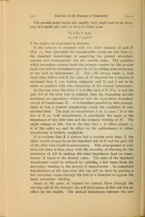
The second-order terms are usually very small and to an accu-
racy of a tenth per cent we have in either case
R* = Ra (i ±a)
«x = a* + 3438 b
if the angles are expressed in minutes.
If the balance is obtained with the slider between B and D(Fig. 2), then (provided the second-order terms are less than a),
the standard transformer is supplying the greater secondary
current and consequently has the smaller ratio. The question
which secondary current leads the primary current by the greater
angle can best be determined once for all by adding some resistance
to the load on transformer X. This will always make 7X lead
more than before and if the value of M required for a balance is
increased then Ix was leading originally and M and b are to be
taken as positive with this connection of the mutual inductance.
In the case when the slider C is to the right of B (Fig. 2) and the
part AB of the slide wire is omitted, then the measuring circuits
introduce no impedance whatever into the equivalent secondary
circuit of transformer X. It is therefore possible by this arrange-
ment to test a current transformer under the condition of zero
external load. The load on transformer 5 or, in case C is to the
left of B, on both transformers, is practically the same as the
impedance of the slide wire and the primary winding of M. The
slight change in this, due to the fact that r, in effect shunts r2 ,
is of the order ar2 and its effect on the performance of either
transformer is entirely negligible.
It is evident that if 5 always had a smaller ratio than X the
slider would always be on the standard side of B and the part ABof the slide wire would be unnecessary. This arrangement is very
desirable since it does away with the necessity of allowing for the
resistance of AB in making the total impedance load on trans-
former X equal to the desired value. The ratio of the standard
transformer could be reduced by omitting a few turns from the
secondary winding in the process of manufacture. In completed
transformers of the hole type this can still be done by passing a
few secondary turns through the hole in a direction to oppose the
main secondary winding.
Since at the point of balance no current flows through the
moving coil of the detector the self-inductance of this coil has no
effect on the results. The mutual inductance between the two

Silsbee] Testing Current Transformers 325
coils of the wattmeter, however, does produce an electromotive
force between the points B and F even when no current flows and
therefore affects the setting. This source of error can easily beeliminated by shifting the position of the control springs so that
the normal zero of the instrument corresponds to the position of
zero mutual inductance. 7
If the current in Phase I of the exciting circuit is in phase with
the current in the transformers and Phase II is 90 from this,
then the slider C may be adjusted with G closed to the right,
and M with G to the left, and the two settings will be independ-
ent of each other. It is not at all necessary, however, that these
phase relations be exact and Phase II may be 6o° from Phase I,
s-fv
i5pr^
1mmLoad a
C^D
fihaseXI
PV
I//TX QBSl
Am.
W7?.
PMsel
Fig.
as in a 3-phase system. If a polyphase supply is not available,
current for Phase I may be drawn through a lamp bank and Phase
II from the same supply through a reactance coil or transformer
winding. With this arrangement it is well not to work the iron
of the core much above its normal rating or the harmonics in the
exciting current will become excessive.
DEFLECTION METHOD
In cases where a variable mutual inductance and slide wire
are not available, but a polyphase supply is at hand, the deflec-
tion method (the connections for which are shown in Fig. 3) may
7 This position can be determined by short-circuiting the moving; coil (or better still by connecting it
to a large inductance of low resistance, such as the 220-volt winding of a transformer) and passing full rated
current through the fixed coil. Under these conditions the pointer deflects toward the position of sero
mutual inductance, and by suitably moving the control springs the desired position can soon be located.
An alternative method is to connect a telephone receiver to the moving coil and pass full-rated current
through the fixed coil. The springs can then be adjusted until no sound is heard in the telephone.
59467°—18 11

326 Bulletin 0} the Bureau of Standards iva.14
be used. The detector W in this method must be of the dyna-
mometer type, and arranged so that one coil may be supplied
from two circuits, one giving a current in phase with the current
in the transformers and the other giving a current having a knownphase relation, preferably quadrature with the former. If Di and
Dq are the deflections in divisions, observed with the excitation
in phase, and in quadrature, respectively, we have
Rx= KDjR* ^3
K Dtan (ax — <x3) = —
p
3, approximately,
where K is the constant of the instrument in amperes per division.
If the wattmeter is excited by passing a current I through its cur-
rent coil,
kK =IqRv
where k is the constant in watts per division for a given range
and RY is the resistance of the voltage circuit of the same range.
If the wrattmeter is excited by applying a voltage EQ to the voltage
circuit, then
In case the second phase available as a source of excitation is
not in quadrature with the first, but gives exciting current which
lags behind the current in the transformers by an angle 6 and pro-
duces a corresponding deflection Dd) then we have
R*_,
KDX
R*~J+
h
, , ,K fPe—Di cos 6\tan («,-«,) = J7(—-^ )
As before, the question which secondary current is the greater
and which leads the primary current by a greater angle can best
be answered by changing the load on one transformer and noting
the effect on the deflections, remembering that an increase in
secondary resistance makes the secondary current smaller and
also makes it lead the primary current more.

Stisbee] Testing Current Transformers 327
The principal limitation of this method is, as mentioned above,
the effect of the impedance of the detector in shifting the load
from one transformer to the other. The change in the equivalent
impedance load on either transformer due to this is given by
y zdAI ZdK'ylDi2 +D <l
2
AZ - j -j
Since this varies with the deflection it is impracticable to allow
for this impedance in arranging the secondary loads on the trans-
formers and it is necessary to reduce AZ not to a comparatively
small and definite value, as in the null method, but to a value
which can be entirely neglected. If the moving coil of a commer-
cial wattmeter is used as a detector, it must therefore be shunted
by a rather low resistance and the sensitivity correspondingly
reduced. The current circuit of a 1 -ampere wattmeter has about
the desired impedance and will be found satisfactory as a detector
for this work. The use of the voltage circuit for the excitation
is also convenient, since it avoids the necessity of a separate
resistance.
The mutual inductance between the coils also introduces an
equivalent load on the transformers, but if over the part of the
scale used the coil is reasonably near the position of zero mutual
inductance, this error will be less than that due to the impedance.
As a specific example of the various factors entering into the
choice of a detector, let us consider the commercial wattmeter
used in the experiments described below, which has the following
constants
:
Nominal current 2. amperes.
Maximum current 3. amperes.
Nominal voltage 75. volts.
Maximum voltage no. volts.
Resistance of fixed coil o. 27 ohm.
Resistance of moving coil 42. ohms.
Resistance of voltage circuit 1, 178. ohms.
Watts per division .5
When this instrument is used with excitation on the voltage
circuit we have
K = : = 4.5 X io~ 3 amperes per division,
2d =o.27 ohm, approximately.
Bulletin oj the Bureau of Standards [Voi.i4
When used with excitation on the current circuit the mov
coil must be shunted to give a resistance of about i ohm so that
K =— — : X — = 6.0 X io—
3
amperes per division,3 X 1 178 i
r r
zd = 1 ohm, approximately.
If the two transformers differ by 1 per cent in current, then at
the 5-ampere point we have in the first case the deflection
D = 8.3 divisions
and AZ = 0.003 ohm,
in the second case
D = 1 1 . divisions
and AZ = o.oi ohm.
A further error arises if the exciting voltages are not in the
correct phase. The magnitude of this effect varies greatly with
the difference in constants of the two transformers. If this dif-
ference is 1 per cent in ratio and 30 minutes in phase angle, a
shift in phase of 7 degrees in the exciting voltage will produce an
error of about 0.1 per cent in ratio and 3 minutes in angle. Anauxiliary 5-ampere wattmeter connected as shown at Wm in
Fig. 3 is a convenient means of determining these phase relations.
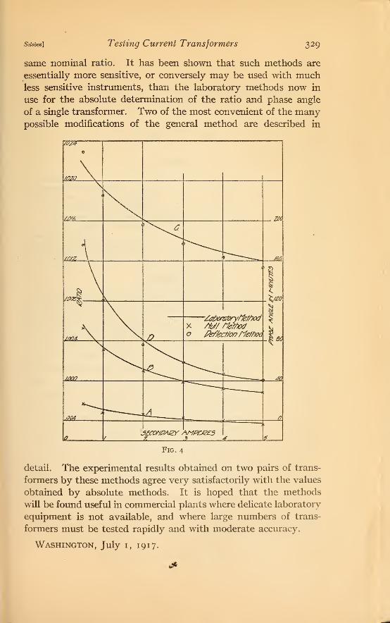
EXPERIMENTAL RESULTS
Both of the methods described above have been tried experi-
mentally and the results are plotted on a large scale in Fig. 4.
Curves .4 and B give the ratio factor and phase angle, respec-
tively, of a 2 5-ampere, 40 volt-ampere portable current trans-
former at 60 cycles. The curve is drawn through values obtained
by a precise laboratory method. The crosses are points observed
by the null method using as a standard a similar transformer
carrying considerably less load. Curves C and D give the ratio
factor and phase angle of another transformer which was tested
by the deflection method. As before, the curves are drawn
through the points obtained by a precise laboratory method andthe circles show the values obtained by the method here proposed.
SUMMARY
A general method has been outlined for the determination of
the ratio and phase angle of current transformers in terms of the
constants of previously calibrated standard transformers of the
Stlsbee] Testing Current Transformers 329
same nominal ratio. It has been shown that such methods are
essentially more sensitive, or conversely may be used with muchless sensitive instruments, than the laboratory methods now in
use for the absolute determination of the ratio and phase angle
of a single transformer. Two of the most convenient of the manypossible modifications of the general method are described in
W24
W2D \ ,
1 > N.
m<i\*
\< "*""*-*w
//)/Z \ t
"~-"~-~—__ SO
\<aI
Si1
Pef/a
(\
/JJO/7}
40
MA ^L____Q
f5£COVPA£Y /
7.
<\MP£&£5
>
4
e
Fig. 4
detail. The experimental results obtained on two pairs of trans-
formers by these methods agree very satisfactorily with the values
obtained by absolute methods. It is hoped that the methods
will be found useful in commercial plants where delicate laboratory
equipment is not available, and where large numbers of trans-
formers must be tested rapidly and with moderate accuracy.
Washington, July 1, 191 7.