current status of safeguards r&d for advanced fuel cycle
TRANSCRIPT
한국원자력연구원Korea Atomic Energy Research Institute
Current Status of Safeguards R&D for
Advanced Fuel Cycle at KAERI
Nov. 13, 2007
Ho-Dong Kim
KAERI
JAEA-IAEA Workshop on Adv. S/G Tech. for NFC
1KAERI
OutlineOutline
Introduction of Future Fuel Cycle Options at KAERI
History of Safeguards R&D at KAERI
DUPIC Safeguards System
ACPF Safeguards System
Other Safeguards R&D for Pyroprocess at KAERI
International Cooperation
Summary
2KAERI
Introduction of Future Fuel Cycle Options at KAERI
Introduction of Future Fuel Cycle Options at KAERI
3KAERI
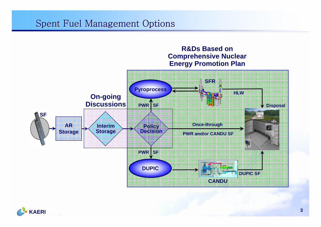
Spent Fuel Management OptionsSpent Fuel Management Options
ARStorage
PWR SF
PWR and/or CANDU SF
HLW
Disposal
R&Ds Based on Comprehensive Nuclear Energy Promotion Plan
Pyroprocess
DUPICDUPIC SF
On-goingDiscussions
Once-throughInterimStorage
PolicyDecision
SFR
CANDU
PWR SF
SF
4KAERI
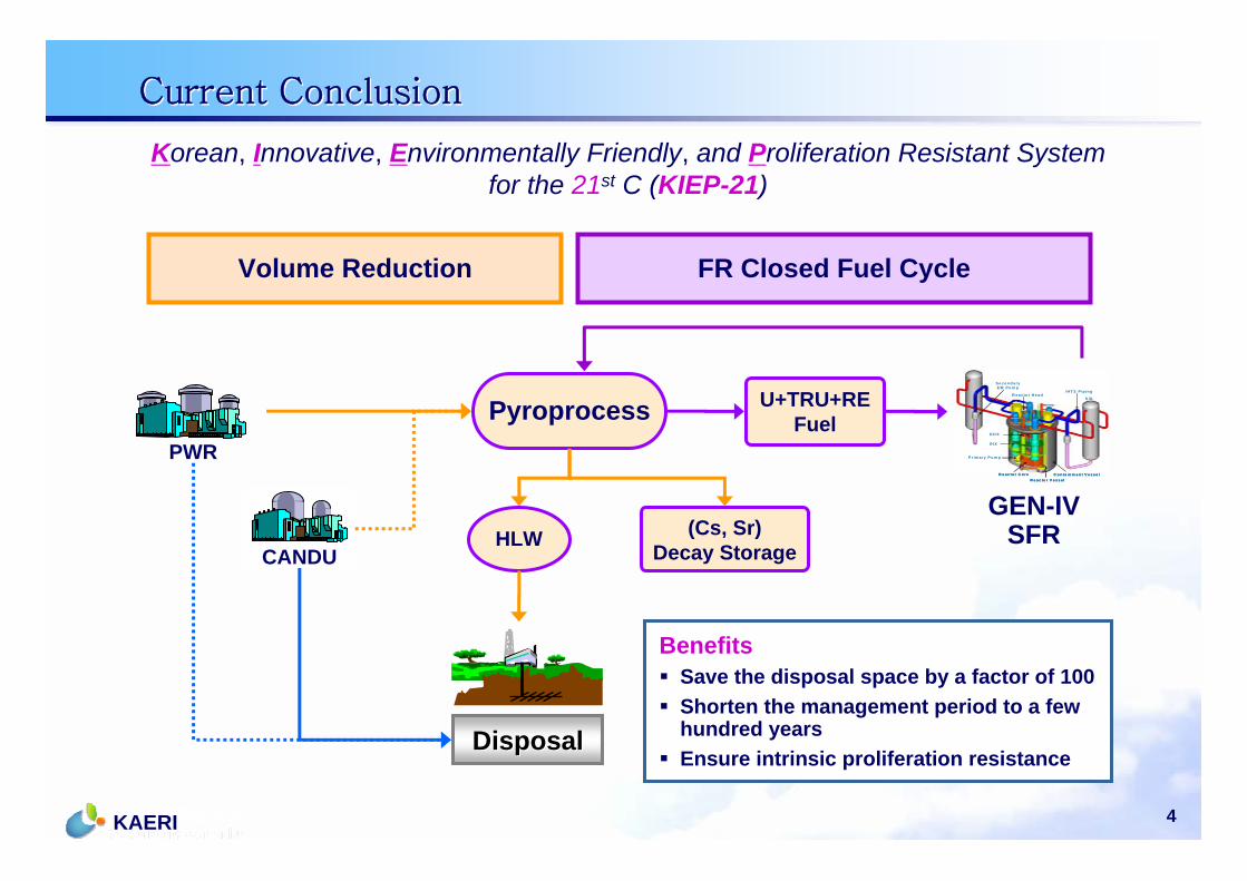
Current ConclusionCurrent Conclusion
FR Closed Fuel Cycle Volume Reduction
Pyroprocess
HLWGEN-IV
SFR
PWR
CANDU
U+TRU+REFuel
(Cs, Sr)Decay Storage
DisposalDisposal
S /G
IH T S P ip in g
S e c o n d a ry E M P u m p
R e a c to r C o re
P r im a ry P u m p
R e a c to r V e s s e l
IH X
D H X
R e a c to r H e a d
C o n ta in m e n t V e s s e l
S /G
IH T S P ip in g
S e c o n d a ry E M P u m p
R e a c to r C o re
P r im a ry P u m p
R e a c to r V e s s e l
IH X
D H X
R e a c to r H e a d
C o n ta in m e n t V e s s e l
Korean, Innovative, Environmentally Friendly, and Proliferation Resistant Systemfor the 21st C (KIEP-21)
BenefitsSave the disposal space by a factor of 100Shorten the management period to a fewhundred yearsEnsure intrinsic proliferation resistance
5KAERI
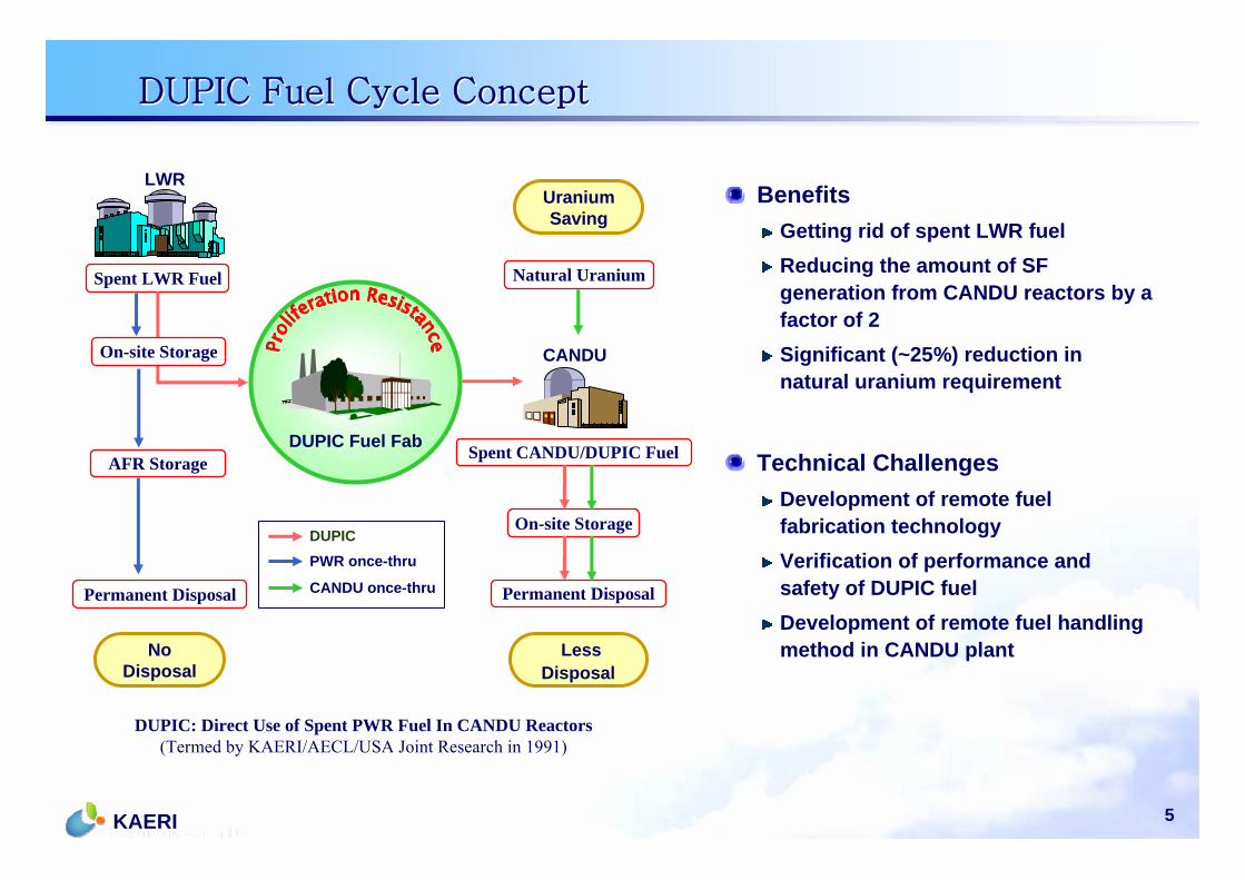
DUPIC Fuel Cycle ConceptDUPIC Fuel Cycle Concept
BenefitsGetting rid of spent LWR fuelReducing the amount of SF generation from CANDU reactors by a factor of 2Significant (~25%) reduction in natural uranium requirement
Technical ChallengesDevelopment of remote fuelfabrication technologyVerification of performance and safety of DUPIC fuelDevelopment of remote fuel handling method in CANDU plant
CANDU
Spent CANDU/DUPIC Fuel
LWR
Spent LWR Fuel
Uranium Saving
No Disposal
Less Disposal
CANDU once-thru
DUPICPWR once-thru
DUPIC Fuel Fab
On-site Storage
Natural Uranium
AFR Storage
Permanent Disposal
On-site Storage
Permanent Disposal
DUPIC: Direct Use of Spent PWR Fuel In CANDU Reactors(Termed by KAERI/AECL/USA Joint Research in 1991)
6KAERI
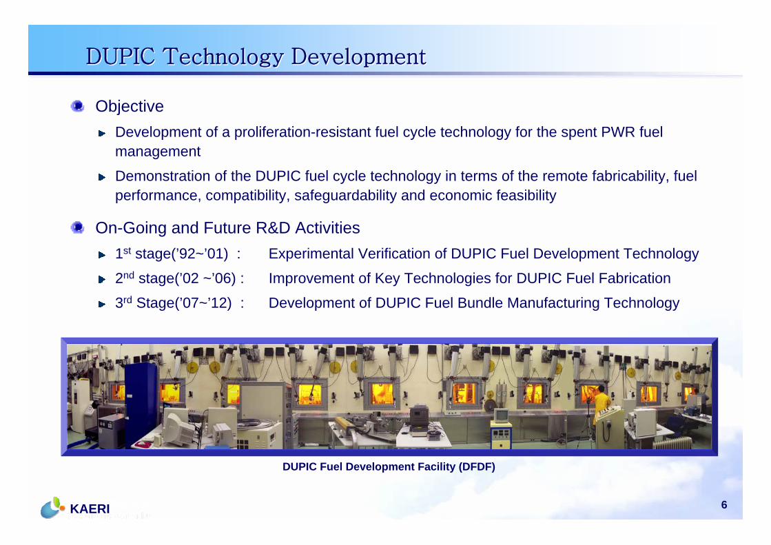
DUPIC Technology DevelopmentDUPIC Technology Development
ObjectiveDevelopment of a proliferation-resistant fuel cycle technology for the spent PWR fuel management
Demonstration of the DUPIC fuel cycle technology in terms of the remote fabricability, fuel performance, compatibility, safeguardability and economic feasibility
On-Going and Future R&D Activities1st stage(’92~’01) : Experimental Verification of DUPIC Fuel Development Technology
2nd stage(’02 ~’06) : Improvement of Key Technologies for DUPIC Fuel Fabrication
3rd Stage(’07~’12) : Development of DUPIC Fuel Bundle Manufacturing Technology
DUPIC Fuel Development Facility (DFDF)
7KAERI
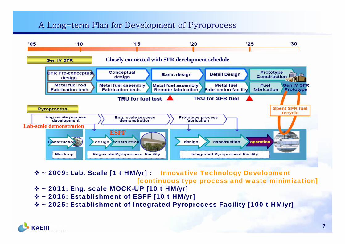
~ 2009: Lab. Scale [1 t HM/yr] : Innovative Technology Development[continuous type process and waste minimization]
~ 2011: Eng. scale MOCK-UP [10 t HM/yr] ~ 2016: Establishment of ESPF [10 t HM/yr]~ 2025: Establishment of Integrated Pyroprocess Facility [100 t HM/yr]
Lab-scale demonstrationESPF
Closely connected with SFR development schedule
A Long-term Plan for Development of PyroprocessA Long-term Plan for Development of Pyroprocess
8KAERI
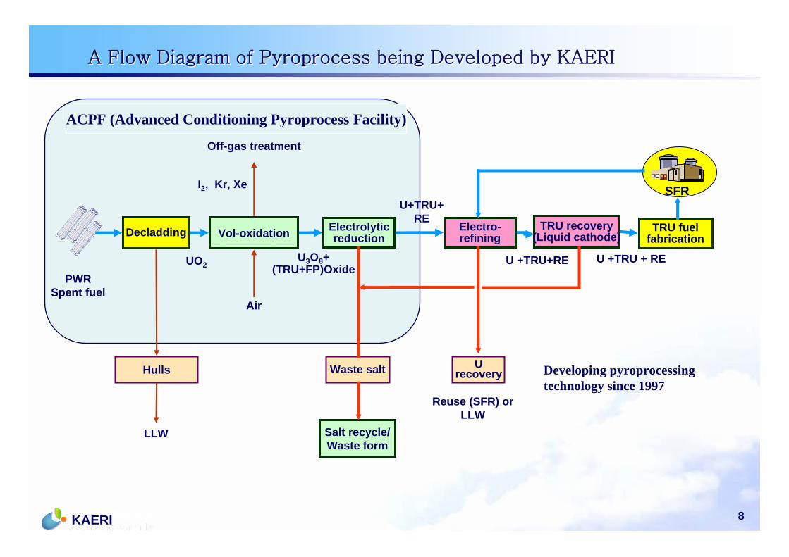
Waste salt
U+TRU+RE
Urecovery
Reuse (SFR) orLLW
SFR
Salt recycle/Waste form
U +TRU+RE U +TRU + RE
Off-gas treatment
I2, Kr, Xe
Air
U3O8+(TRU+FP)Oxide
Hulls
LLW
UO2
PWRSpent fuel
Electrolyticreduction
TRU recovery(Liquid cathode)
Electro-refiningDecladding Vol-oxidation TRU fuel
fabrication
ACPF (Advanced Conditioning Pyroprocess Facility)
Developing pyroprocessing technology since 1997
A Flow Diagram of Pyroprocess being Developed by KAERIA Flow Diagram of Pyroprocess being Developed by KAERI
9KAERI
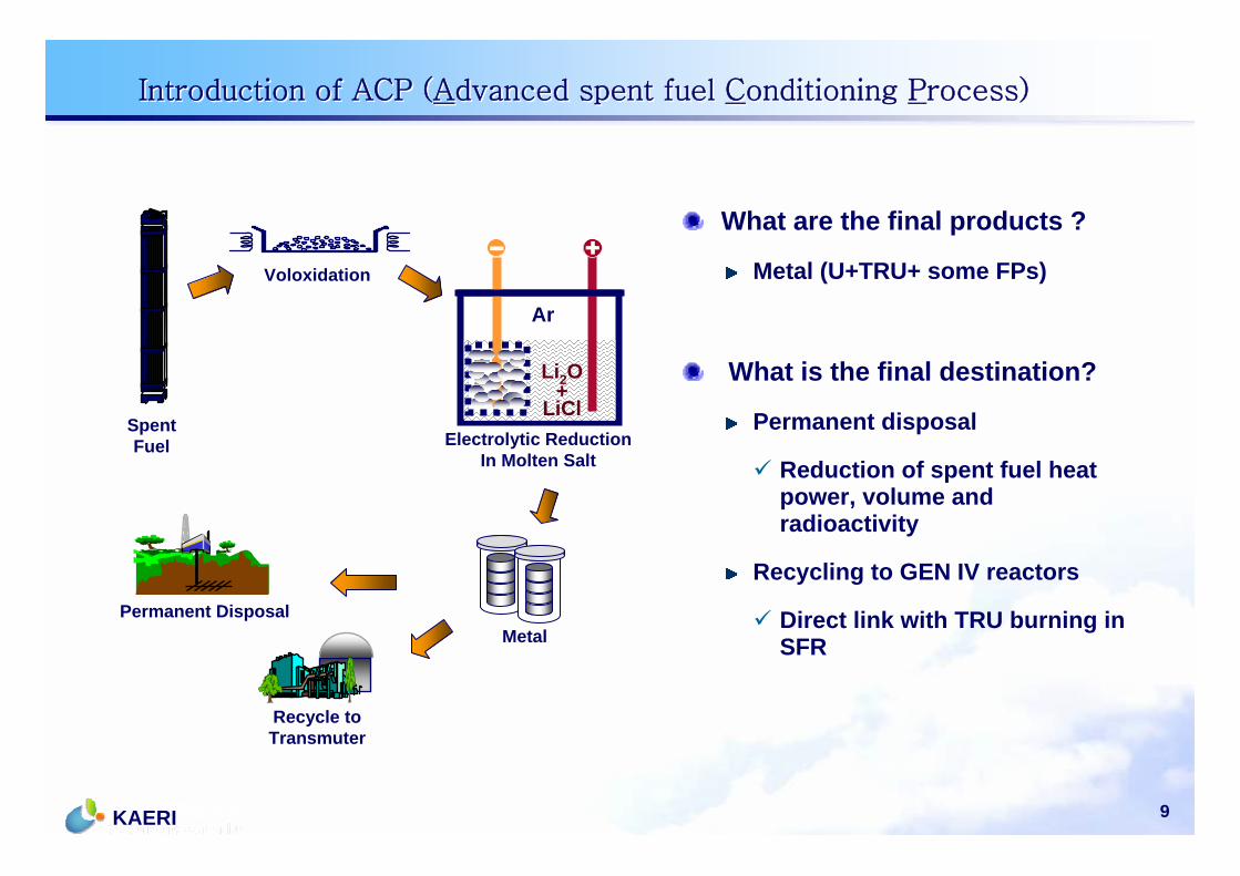
Voloxidation
Electrolytic ReductionIn Molten Salt
MetalPermanent Disposal
SpentFuel
Li2O+LiCl
Ar
Recycle toTransmuter
What are the final products ?
Metal (U+TRU+ some FPs)
What is the final destination?
Permanent disposal
Reduction of spent fuel heat power, volume and radioactivity
Recycling to GEN IV reactors
Direct link with TRU burning in SFR
Introduction of ACP (Advanced spent fuel Conditioning Process)Introduction of ACP (Advanced spent fuel Conditioning Process)
10KAERI
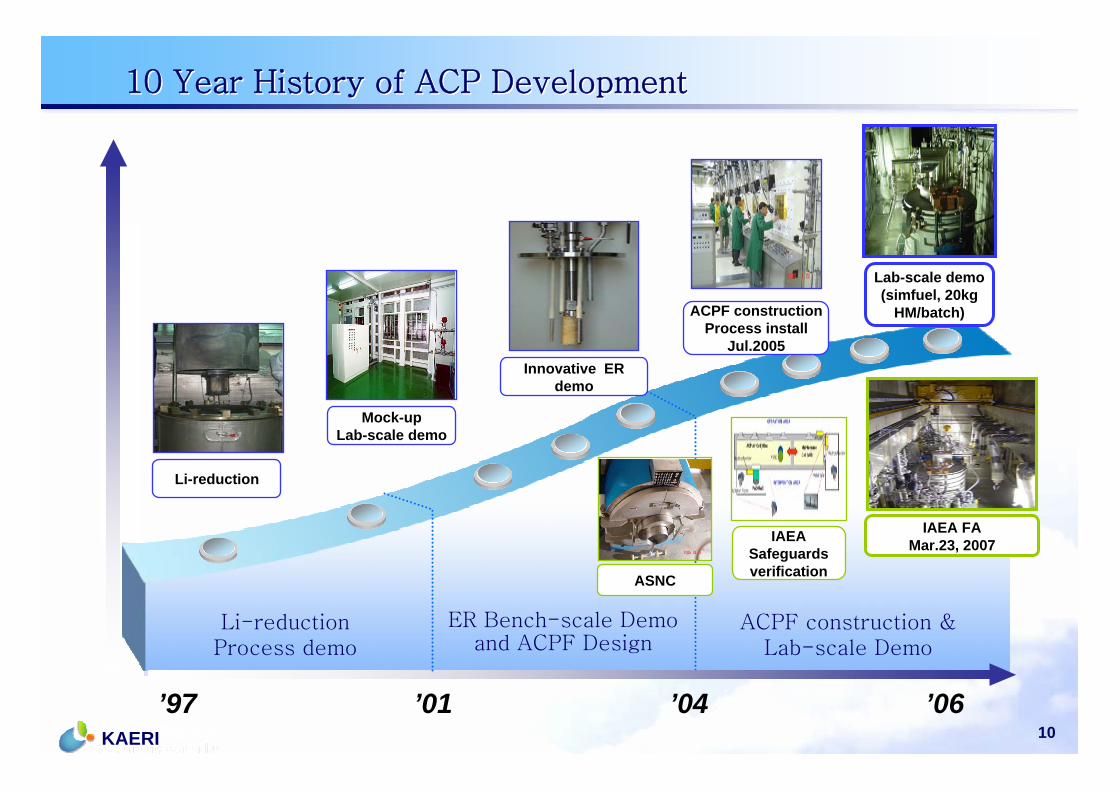
10 Year History of ACP Development10 Year History of ACP Development
’97 ’01 ’04 ’06
Li-reduction Process demo
ER Bench-scale Demo and ACPF Design
ACPF construction & Lab-scale Demo
Mock-upLab-scale demo
Innovative ER demo
ACPF constructionProcess install
Jul.2005
Lab-scale demo (simfuel, 20kg
HM/batch)
Li-reduction
ASNC
IAEA FAMar.23, 2007IAEA
Safeguards verification
11KAERI
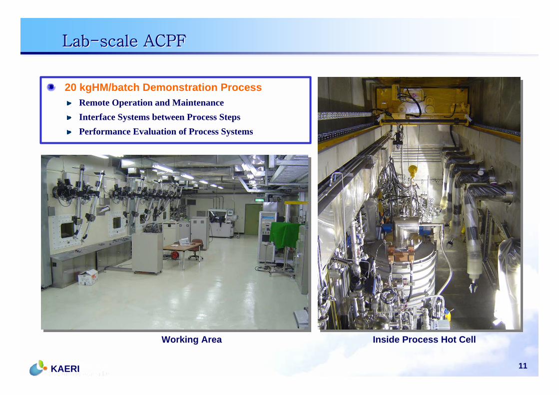
Lab-scale ACPFLab-scale ACPF
20 kgHM/batch Demonstration ProcessRemote Operation and MaintenanceInterface Systems between Process StepsPerformance Evaluation of Process Systems
Working Area Inside Process Hot Cell
12KAERI
History of Safeguards R&D at KAERIHistory of Safeguards R&D at KAERI
13KAERI
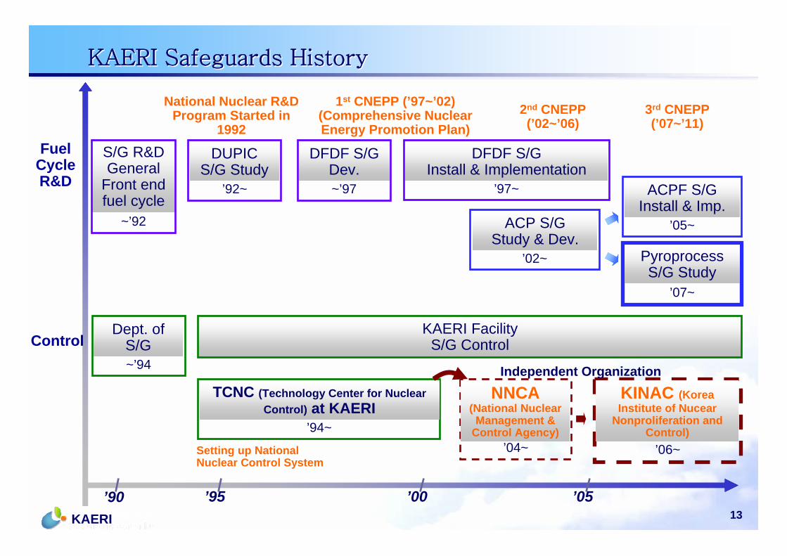
KAERI Safeguards HistoryKAERI Safeguards History
S/G R&DGeneral
Front end fuel cycle
DUPIC S/G Study
’92~
DUPIC S/G Study
~’97
DFDF S/G Dev.
’02~
ACP S/G Study & Dev.
’05~
ACPF S/GInstall & Imp.
’07~
Pyroprocess S/G Study
DUPIC S/G Study
~’94
Dept. of S/G
KAERI FacilityS/G Control
’94~
TCNC (Technology Center for Nuclear Control) at KAERI
’04~
NNCA (National Nuclear
Management & Control Agency)
’06~
KINAC (Korea Institute of Nucear
Nonproliferation and Control)
Independent Organization
National Nuclear R&D Program Started in
1992
1st CNEPP (’97~’02)(Comprehensive Nuclear Energy Promotion Plan)
2nd CNEPP (’02~’06)
3rd CNEPP (’07~’11)
Setting up National Nuclear Control System
’90 ’95 ’00 ’05
Fuel Cycle R&D
Control
’97~
DFDF S/GInstall & Implementation
~’92
14KAERI
DUPIC SafeguardsDUPIC Safeguards
15KAERI
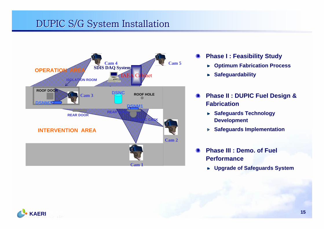
DUPIC S/G System InstallationDUPIC S/G System Installation
ISOLATION ROOM
OPERATION AREA
ROOF HOLEROOF DOOR
INTERVENTION AREA
DSNC
DSNM1
SDIS DAQ System
REAR DOORREAR DOOR
IAEA Cabinet
PADIRAC CASK
Cam 1
Cam 3
Cam 4 Cam 5
Cam 2
DSNM2
Phase I : Feasibility StudyOptimum Fabrication ProcessSafeguardability
Phase II : DUPIC Fuel Design & Fabrication
Safeguards Technology DevelopmentSafeguards Implementation
Phase III : Demo. of Fuel Performance
Upgrade of Safeguards System
16KAERI
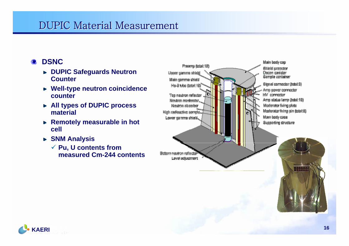
DUPIC Material MeasurementDUPIC Material Measurement
DSNCDUPIC Safeguards Neutron CounterWell-type neutron coincidence counterAll types of DUPIC process materialRemotely measurable in hot cellSNM Analysis
Pu, U contents from measured Cm-244 contents

17KAERI
Neutron Counter(DSNC)
CaptureCard
DAQCard
Image DataProcessing
Radiation Data Processing
Diagnosis
IAEACabinet
Remote Monitoring
Network
DAQ Server
DUPIC Cameras
Data Storage
Graphic User Interface
Neutron Monitor(DSNM)
DUPIC Intelligent Surveillance SystemDUPIC Intelligent Surveillance System
18KAERI
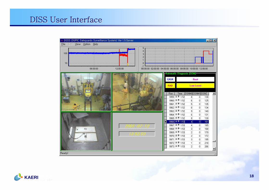
DISS User InterfaceDISS User Interface

19KAERI
ACPF Safeguards SystemACPF Safeguards System
20KAERI
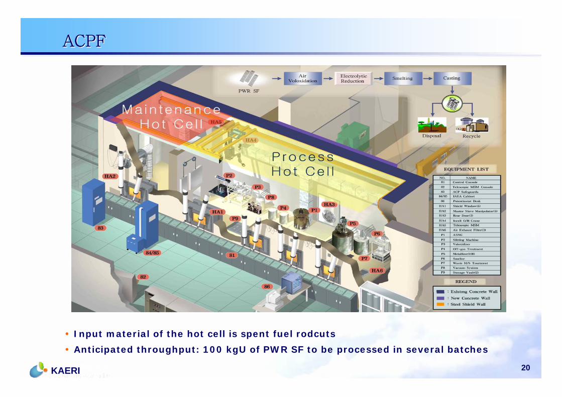
ACPFACPF
• Input material of the hot cell is spent fuel rodcuts
• Anticipated throughput: 100 kgU of PWR SF to be processed in several batches
21KAERI
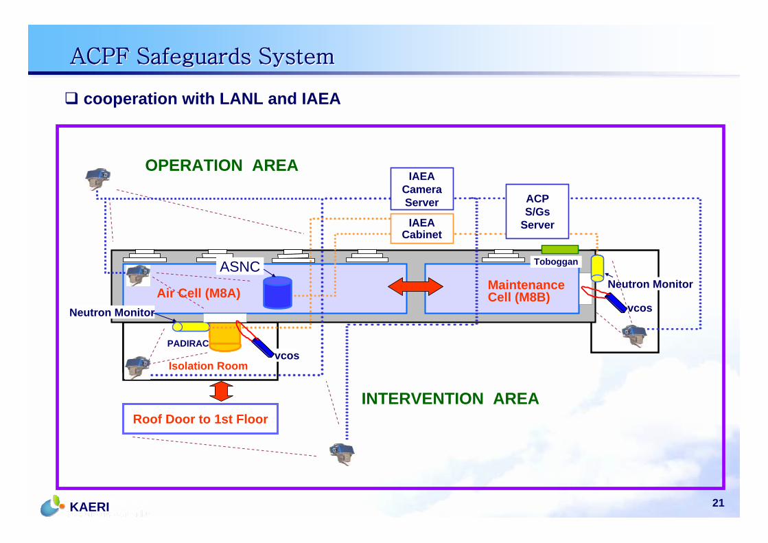
ACPF Safeguards SystemACPF Safeguards System
cooperation with LANL and IAEA
ACP Air Cell (M7A) Maintenance Cell (M7B)
Toboggan
PADIRAC
Roof Door to 1st Floor
10
34
10
OPERATION AREA
INTERVENTION AREA
Air Cell (M8A)
Toboggan
PADIRAC
Isolation Room
IAEA Cabinet
Neutron Monitor
ASNC
ACPS/Gs
Server
IAEA CameraServer
Neutron MonitorMaintenanceCell (M8B)
vcos
vcos
22KAERI
Safeguards ImplementationSafeguards Implementation
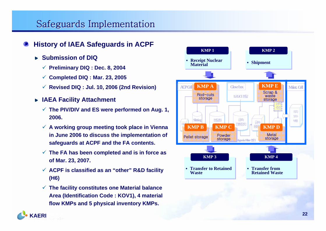
History of IAEA Safeguards in ACPF
Submission of DIQ Preliminary DIQ : Dec. 8, 2004
Completed DIQ : Mar. 23, 2005
Revised DIQ : Jul. 10, 2006 (2nd Revision)
IAEA Facility AttachmentThe PIV/DIV and ES were performed on Aug. 1, 2006.
A working group meeting took place in Vienna in June 2006 to discuss the implementation of safeguards at ACPF and the FA contents.
The FA has been completed and is in force as of Mar. 23, 2007.
ACPF is classified as an “other” R&D facility (H6)
The facility constitutes one Material balance Area (Identification Code : KOV1), 4 material flow KMPs and 5 physical inventory KMPs.
Receipt Nuclear MaterialReceipt Nuclear Material
KMP 1
ShipmentShipment
KMP 2
Transfer from Retained WasteTransfer from Retained Waste
KMP 4
Transfer to Retained WasteTransfer to Retained Waste
KMP 3
Maint. Cell
금속용융로
금속용융로
금속주조
폐용융염Bead화
폐용융염Bead화
ACP Cell
Slitting장치
Slitting장치
분말화장치
분말화장치Hull
수집
Hull수집
U3O8분말
Li/LiCl분말Rod-cuts
Cask 접속
U-metal
금속전환장치
금속전환장치
Magnesia Filter 분리UO2펠렛
Glove box
유지
보수
부품
유지
보수
부품
Hull
Maint. Cell
금속용융로
금속용융로
금속주조금속주조
폐용융염Bead화
폐용융염Bead화
ACP Cell
Slitting장치
Slitting장치
분말화장치
분말화장치Hull
수집
Hull수집
U3O8분말
Li/LiCl분말Rod-cuts
Cask 접속
U-metal
금속전환장치
금속전환장치
Magnesia Filter 분리UO2펠렛
Glove box
유지
보수
부품
유지
보수
부품
Hull
Rod-cuts storage
Rod-cuts storage
KMP A
Pellet storagePellet storage
KMP B
Powder storagePowder storage
KMP CMetal
storageMetal
storage
KMP D
Scrap & waste
storage
Scrap & waste
storage
KMP E
23KAERI
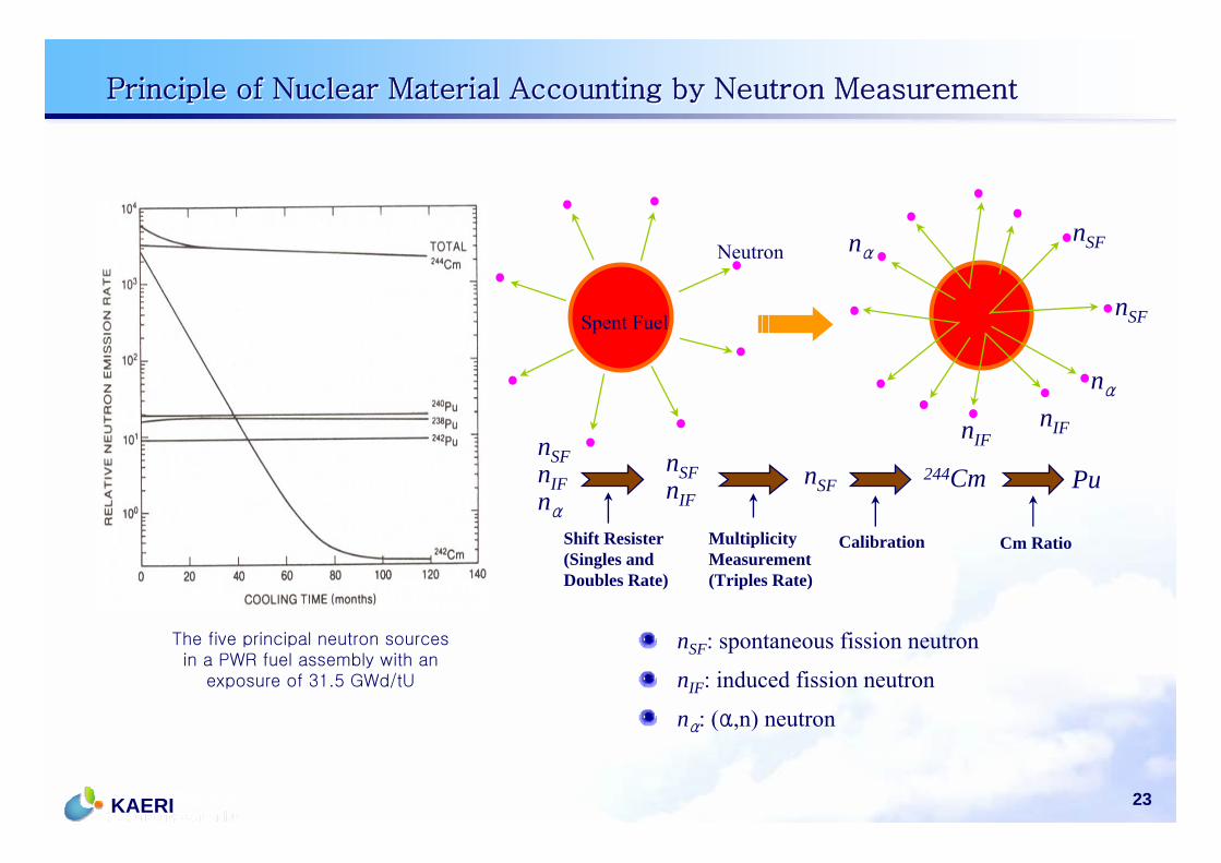
nSF: spontaneous fission neutron
nIF: induced fission neutron
nα: (α,n) neutron
Spent Fuel
Shift Resister(Singles and Doubles Rate)
MultiplicityMeasurement(Triples Rate)
Calibration Cm Ratio
NeutronnSF
nSF
nα
nIFnIF
nα
nSFnIFnα
nSFnIF
nSF244Cm Pu
Principle of Nuclear Material Accounting by Neutron MeasurementPrinciple of Nuclear Material Accounting by Neutron Measurement
The five principal neutron sources in a PWR fuel assembly with an
exposure of 31.5 GWd/tU
24KAERI
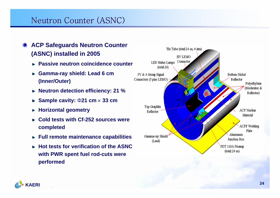
ACP Safeguards Neutron Counter (ASNC) installed in 2005
Passive neutron coincidence counter
Gamma-ray shield: Lead 6 cm (Inner/Outer)
Neutron detection efficiency: 21 %
Sample cavity: Φ21 cm × 33 cm
Horizontal geometry
Cold tests with Cf-252 sources were completed
Full remote maintenance capabilities
Hot tests for verification of the ASNC with PWR spent fuel rod-cuts were performed
Neutron Counter (ASNC)Neutron Counter (ASNC)

25KAERI
Front view of ASNC - Open hood (Maintenance)Front view of ASNC (Normal operation)
LEMO Connectors
ASNC Installation ASNC Installation
ASNC installed in the ACPF hot cell
LED Panel, Junction Box, LEMO con-/disconnection of the ASNC
LEMO Connectors
LED Panel
Normal Operation
Maintenance(hood open)
Junction Box
Replacement of damage part
26KAERI
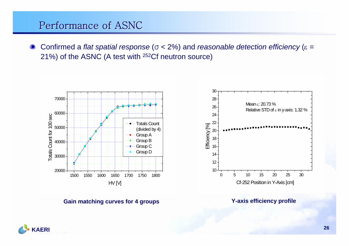
Gain matching curves for 4 groups Y-axis efficiency profile
Confirmed a flat spatial response (σ < 2%) and reasonable detection efficiency (ε = 21%) of the ASNC (A test with 252Cf neutron source)
1500 1550 1600 1650 1700 1750 180020000
30000
40000
50000
60000
70000
Tota
ls Co
unt f
or 1
00 s
ec
HV [V]
Totals Count (divided by 4)
Group A Group B Group C Group D
Performance of ASNCPerformance of ASNC
0 5 10 15 20 25 3010
12
14
16
18
20
22
24
26
28
30
Effic
ienc
y [%
]
Cf-252 Position in Y-Axis [cm]
Mean ε: 20.73 %Relative STD of ε in y-axis: 1.32 %

27KAERI
ASNC Hot TestASNC Hot Test
ASNC hot test with spent fuel rod cutsSpent fuel rod cuts stored in a PE cask
The hot test verification of ASNC using the spent fuel rod-cuts was performed with cooperation between KAERI and LANL in Aug., 2007.
IAEA expert participated in the test as an observer.
Test objectives Calibration of the ASNC for the real hot materials including Cm-244
Gamma pileup check and HV setting
Spent Fuel SpecificationsTotal 8 rod-cut samples, 2 years cooling
PWR SF 3 rod-cuts 1 cm long (52 GWD/MTU)
PWR SF 5 rod-cuts 25 cm long from J502 Assembly C16 rod (60 GWD/MTU)
Drs. Menlove and Belian at the ACPF
28KAERI
Spent Fuel Rod-cuts Spec.Spent Fuel Rod-cuts Spec.
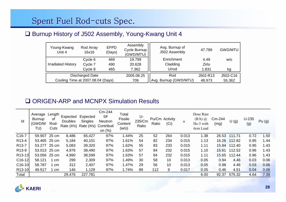
Burnup History of J502 Assembly, Young-Kwang Unit 4
Id
AverageBurnup
(GWD/MTU)
Lengthof
Rod-Cuts
ExpectedDoubles
Rate (#/s)
ExpectedSingles
Rate (#/s)
Cm-244SF
NeutronContributi
on (%)
TotalFissile
Content(w/o)
U-235/Cm
Ratio
Pu/CmRatio
Activity(Ci) α
Dose Rate(R/h) @
He-3 with6cm Lead
Cm-244(mg) U (g) U-235
(g) Pu (g)
C16-7 59.907 25 cm 8,486 65,427 97% 1.44% 25 52 264 0.013 1.38 26.53 111.71 0.72 1.50R13-4 53.465 25 cm 5,184 40,101 97% 1.61% 54 82 234 0.015 1.13 16.26 112.82 0.95 1.44R13-7 53.277 25 cm 5,083 39,320 97% 1.62% 55 83 233 0.015 1.11 15.94 112.40 0.95 1.43R13-9 53.013 25 cm 4,976 38,490 97% 1.63% 57 84 232 0.015 1.10 15.61 112.52 0.96 1.43R13-13 53.056 25 cm 4,990 38,599 97% 1.63% 57 84 232 0.015 1.11 15.65 112.44 0.96 1.43C16-12 58.121 1 cm 299 2,309 97% 1.49% 30 58 10 0.013 0.05 0.94 4.46 0.03 0.06C16-10 58.787 1 cm 312 2,407 97% 1.47% 29 56 10 0.013 0.05 0.98 4.46 0.03 0.06R13-10 49.517 1 cm 146 1,129 97% 1.74% 89 112 9 0.017 0.05 0.46 4.51 0.04 0.06Total 29,476 227,781 6.00 92.37 575.32 4.64 7.39
ORIGEN-ARP and MCNPX Simulation Results
Young-KwangUnit 4
Rod Array16x16
EFPD(Days)
AssemblyCycle Burnup(GWD/MTU)
47.789 GWD/MTU
Cycle 6 469 19.799 4.49 w/oCycle 7 490 20.628 ZirloCycle 8 465 7.362 1.831 kg
2005.08.25 J502-R13 J502-C16709 48.973 55.362
Irradiated History
RodAvg. Burnup (GWD/MTU)
Avg. Burnup ofJ502 Assembly
EnrichmentCladding
U/rod
Cooling Time at 2007.08.04 (Days)Discharged Date
29KAERI
ASNC Hot Test Results (1)ASNC Hot Test Results (1)
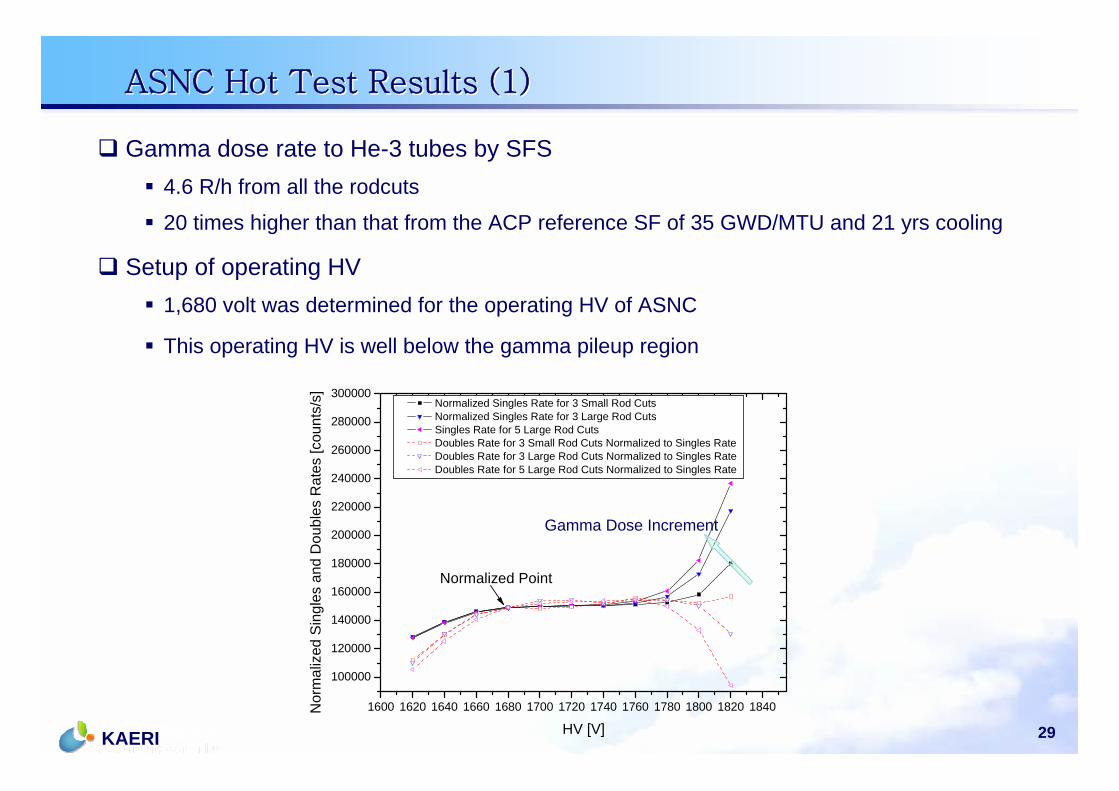
Gamma dose rate to He-3 tubes by SFS4.6 R/h from all the rodcuts
20 times higher than that from the ACP reference SF of 35 GWD/MTU and 21 yrs cooling
Setup of operating HV1,680 volt was determined for the operating HV of ASNC
This operating HV is well below the gamma pileup region
1600 1620 1640 1660 1680 1700 1720 1740 1760 1780 1800 1820 1840
100000
120000
140000
160000
180000
200000
220000
240000
260000
280000
300000
Nor
mal
ized
Sin
gles
and
Dou
bles
Rat
es [c
ount
s/s]
HV [V]
Normalized Singles Rate for 3 Small Rod Cuts Normalized Singles Rate for 3 Large Rod Cuts Singles Rate for 5 Large Rod Cuts Doubles Rate for 3 Small Rod Cuts Normalized to Singles Rate Doubles Rate for 3 Large Rod Cuts Normalized to Singles Rate Doubles Rate for 5 Large Rod Cuts Normalized to Singles Rate
Normalized Point
Gamma Dose Increment
30KAERI
0 10 20 30 40 50 60 70 80
0
20000
40000
60000
80000
100000
120000
140000
160000
180000
Sin
gles
Rat
e [c
ount
s/s]
Cm-244 [mg]
Y = 26.2 + 2218*X
ASNC Hot Test Results (2)ASNC Hot Test Results (2)
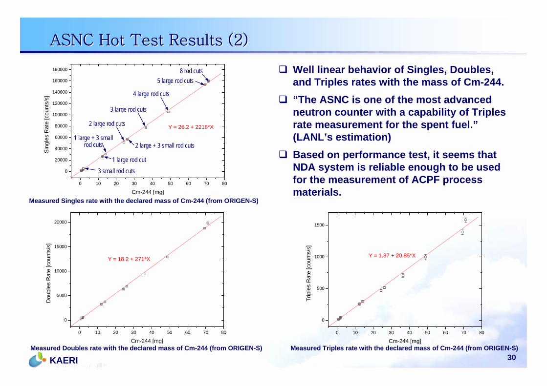
Well linear behavior of Singles, Doubles, and Triples rates with the mass of Cm-244.“The ASNC is one of the most advanced neutron counter with a capability of Triples rate measurement for the spent fuel.”(LANL’s estimation)Based on performance test, it seems that NDA system is reliable enough to be used for the measurement of ACPF process materials.
3 small rod cuts1 large rod cut
1 large + 3 small rod cuts
2 large rod cuts
2 large + 3 small rod cuts
3 large rod cuts
4 large rod cuts
5 large rod cuts
Measured Singles rate with the declared mass of Cm-244 (from ORIGEN-S)
Measured Doubles rate with the declared mass of Cm-244 (from ORIGEN-S) Measured Triples rate with the declared mass of Cm-244 (from ORIGEN-S)
8 rod cuts
0 10 20 30 40 50 60 70 80
0
5000
10000
15000
20000
Y = 18.2 + 271*X
Dou
bles
Rat
e [c
ount
s/s]
Cm-244 [mg]0 10 20 30 40 50 60 70 80
0
500
1000
1500
Y = 1.87 + 20.85*X
Trip
les
Rat
e [c
ount
s/s]
Cm-244 [mg]
31KAERI
Singles/Doubles and Doubles/Triples RatiosSingles/Doubles and Doubles/Triples Ratios
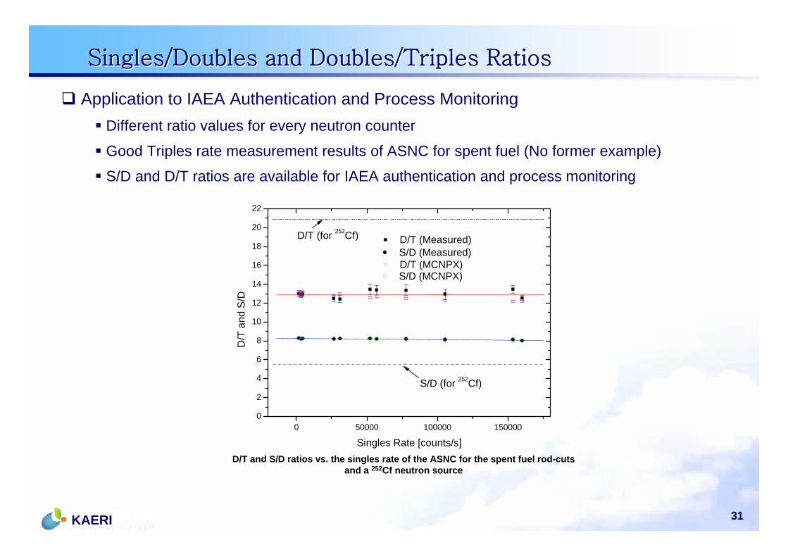
D/T and S/D ratios vs. the singles rate of the ASNC for the spent fuel rod-cuts and a 252Cf neutron source
Application to IAEA Authentication and Process MonitoringDifferent ratio values for every neutron counter
Good Triples rate measurement results of ASNC for spent fuel (No former example)
S/D and D/T ratios are available for IAEA authentication and process monitoring
0 50000 100000 1500000
2
4
6
8
10
12
14
16
18
20
22
D/T (for 252Cf)
D/T
and
S/D
Singles Rate [counts/s]
D/T (Measured)
S/D (for 252Cf)
S/D (Measured) D/T (MCNPX) S/D (MCNPX)
32KAERI
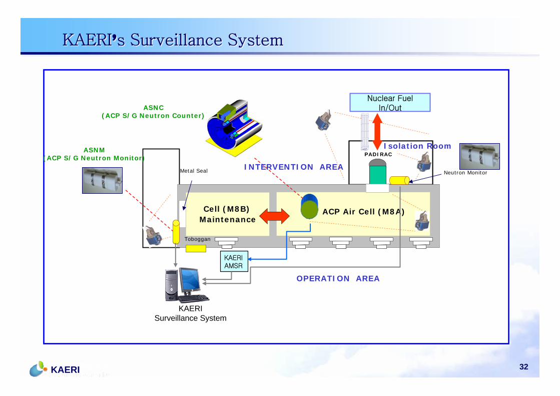
ACP Air Cell (M7A)Maintenance
Cell (M7B)
Toboggan
PADIRAC
10
4
10 ACP Air Cell (M8A)Maintenance Cell (M8B)
Toboggan
PADIRAC
Neutron MonitorMetal Seal
ASNM(ACP S/G Neutron Monitor)
ABCD
ASNC(ACP S/G Neutron Counter)
Nuclear Fuel In/Out
KAERIAMSR
INTERVENTION AREA
OPERATION AREA
KAERISurveillance System
Isolation Room
KAERI’s Surveillance SystemKAERI’s Surveillance System

33KAERI
C/S Plan during Hot TestC/S Plan during Hot Test
OPERATION AREA
INTERVENTION AREA
Neutron Monitor
Toboggan
Neutron Monitor
IAEA Cabinet
IAEACameraServer ACP
S/GsServer
Maintenance Cell(M8B)
ASNC
ACP Air Cell (M8A)
PADIRACPADIRAC
Roof Door to 1st Floor
Isolation Room
vcos
V
34KAERI
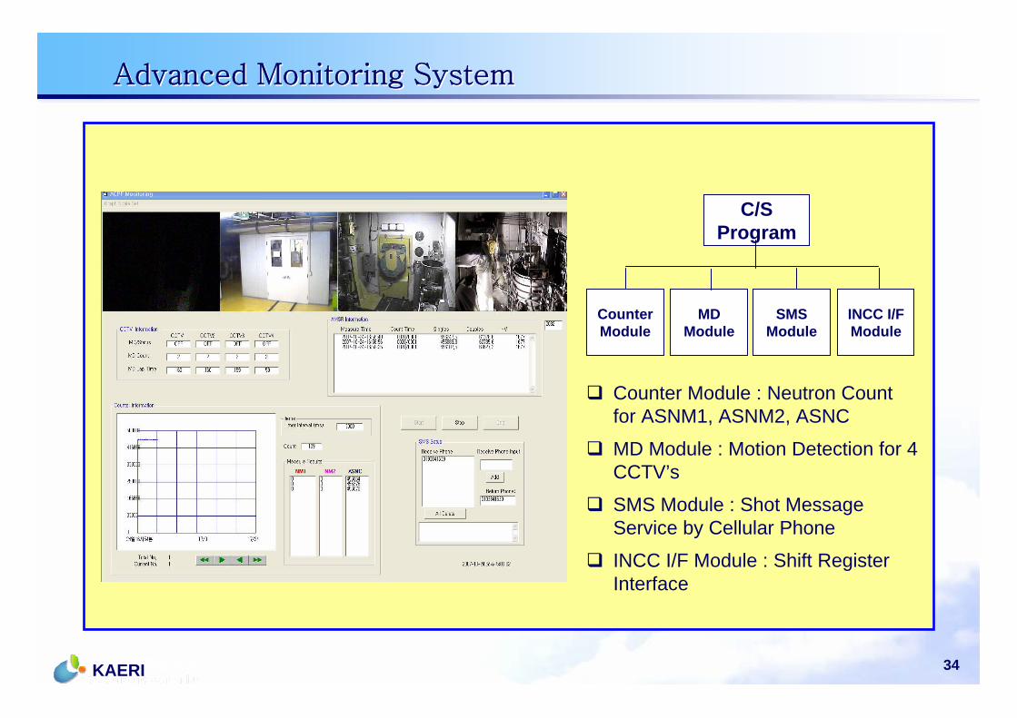
C/S Program
Counter Module
MD Module
SMS Module
INCC I/F Module
Counter Module : Neutron Count for ASNM1, ASNM2, ASNC
MD Module : Motion Detection for 4 CCTV’s
SMS Module : Shot Message Service by Cellular Phone
INCC I/F Module : Shift Register Interface
Advanced Monitoring SystemAdvanced Monitoring System
35KAERI
Other Safeguards R&D for Pyroprocess at KAERI
Other Safeguards R&D for Pyroprocess at KAERI
36KAERI
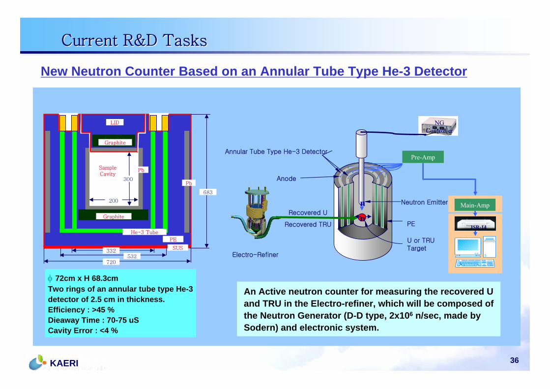
New Neutron Counter Based on an Annular Tube Type He-3 Detector
300
200
683
332532
720
SampleCavity
LID
Graphite
Graphite
He-3 Tube
PE
SUS
Pb
Pb
Electro-Refiner
Pre-Amp
Main-Amp
JSR-14
NG Controller
Recovered U
Recovered TRU
n
n
Neutron Emitter
U or TRUTarget
Annular Tube Type He-3 Detector
Anode
PE
φ 72cm x H 68.3cm Two rings of an annular tube type He-3 detector of 2.5 cm in thickness.Efficiency : >45 %Dieaway Time : 70-75 uSCavity Error : <4 %
An Active neutron counter for measuring the recovered U and TRU in the Electro-refiner, which will be composed of the Neutron Generator (D-D type, 2x10⁶ n/sec, made by Sodern) and electronic system.
Current R&D TasksCurrent R&D Tasks
37KAERI
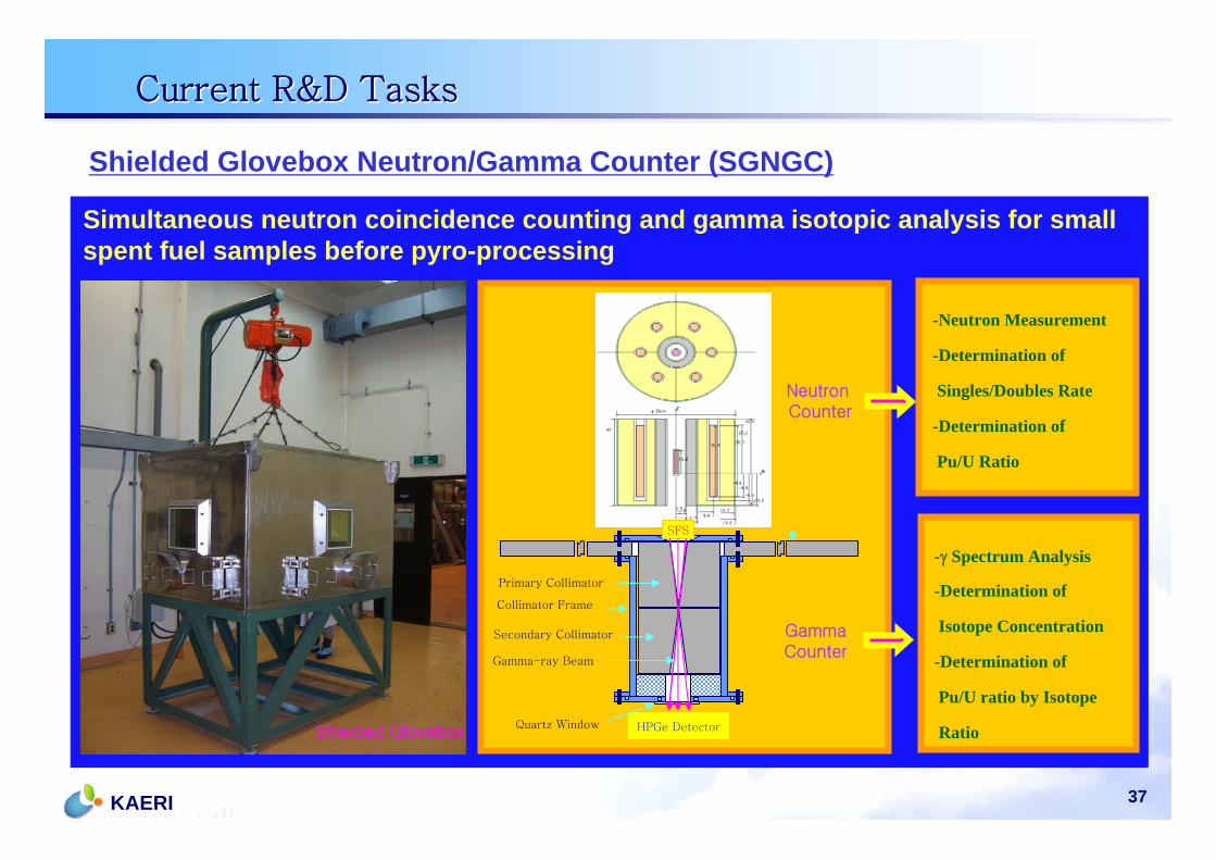
Shielded Glovebox Neutron/Gamma Counter (SGNGC)
Simultaneous neutron coincidence counting and gamma isotopic analysis for small spent fuel samples before pyro-processing
SFS
HPGe Detector
Collimator Frame
Primary Collimator
Secondary Collimator
Quartz Window
Gamma-ray Beam
Shielded Glovebox
Neutron Counter
GammaCounter
-Neutron Measurement
-Determination of
Singles/Doubles Rate
-Determination of
Pu/U Ratio
-γ Spectrum Analysis
-Determination of
Isotope Concentration
-Determination of
Pu/U ratio by Isotope
Ratio
Current R&D TasksCurrent R&D Tasks
38KAERI
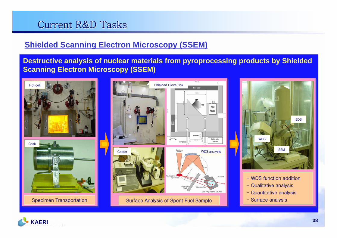
Shielded Scanning Electron Microscopy (SSEM)
Destructive analysis of nuclear materials from pyroprocessing products by Shielded Scanning Electron Microscopy (SSEM)
Specimen Transportation Surface Analysis of Spent Fuel Sample
- WDS function addition
- Qualitative analysis
- Quantitative analysis
- Surface analysis
Hot cell
Cask
Shielded Glove Box
WDS
Coater
EDS
SEMWDS analysis
Current R&D TasksCurrent R&D Tasks
39KAERI
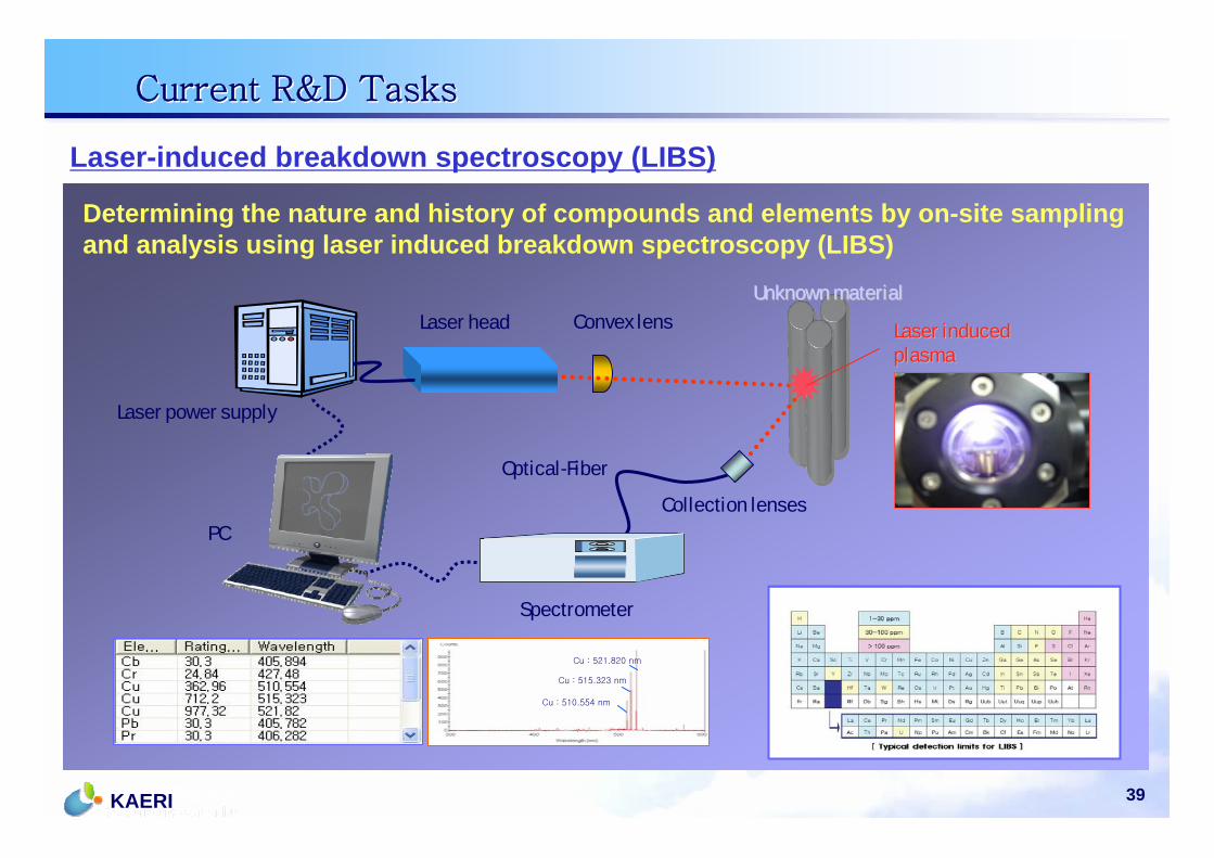
Laser-induced breakdown spectroscopy (LIBS)
Determining the nature and history of compounds and elements by on-site sampling and analysis using laser induced breakdown spectroscopy (LIBS)
Laser head
Optical-Fiber
PC
Spectrometer
Collection lenses
Convex lens
Laser power supply
Unknown materialUnknown material
Laser induced Laser induced plasmaplasma
Cu : 510.554 nm
Cu : 515.323 nm
Cu : 521.820 nm
Current R&D TasksCurrent R&D Tasks
40KAERI
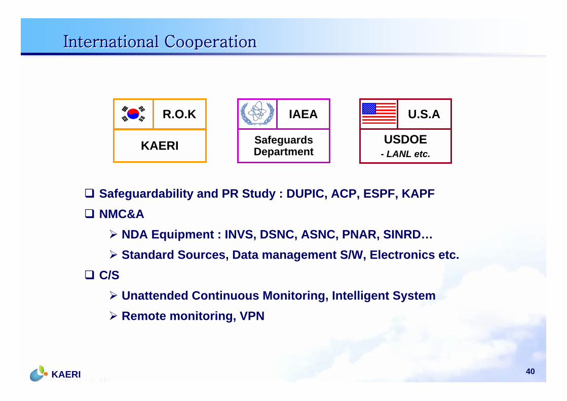
International CooperationInternational Cooperation
U.S.A
USDOE- LANL etc.
IAEA
SafeguardsDepartment
R.O.K
KAERI
Safeguardability and PR Study : DUPIC, ACP, ESPF, KAPFNMC&A
NDA Equipment : INVS, DSNC, ASNC, PNAR, SINRD…Standard Sources, Data management S/W, Electronics etc.
C/SUnattended Continuous Monitoring, Intelligent SystemRemote monitoring, VPN
41KAERI
SummarySummary
The lab-scale Fuel Cycle Facility safeguards system in KAERI was successfully designed and established under an international cooperation program.
Based on performance test, it seems that NDA system is reliable enough to be used for the measurement of the process materials.
Some R&D for increasing PR and IAEA authentication method will continue.
Pyroprocess material measurement system, Surveillance system, and near real time accountability system will be integrated into a single safeguards system in the next R&D stage.
The KAERI will continue to work closely with the IAEA and international partners for the future nuclear fuel cycle
Safeguardability and PR evaluation
Advanced NDA and monitoring technology development
Safeguards system development