current situation and issues of myanmar's bridge work the project, incenter training and on-...
TRANSCRIPT

Current Situation and Issues of Myanmar's Bridge Work
September, 2012
Authorized NPO
Japan Infrastructure Partners ( JIP )

NGO Technology Transfer Support Program
Ministry of Land, Infrastructure, Transport and Tourism

Contents
1. Introduction …… 1
2. Overview of the Bridges in Myanmer …… 2
3. Outline of the Bridge Full Inspection Conducted in Myanmar in 2009 …… 6
4. Outline of the Bridges Surveyed …… 10
5. Main Issues …… 49
Appendix
Some new findings from the study [Research Study on Review and Application of the Bridge
Engineering Training Center Project in Myanmar] by JICA,2012

1
1. Introduction
In Myanmar, the Japan International Cooperation Agency (JICA) conducted the Bridge
Engineering Training Center Project (BETC) from 1979 to 1985 for engineers of the former
Construction Corporation (currently Public Works [PW]) which is a subsidiary organization of
the Ministry of Construction (MOC).
Under the project, in-center training and on-the-job training were conducted under the
guidance of Japanese experts dispatched to Myanmar. Through the former, around 60
engineers mastered the design methods of bridge substructures, reinforced concrete
bridges, and prestressed concrete bridges, and through the latter, a prestressed concrete
bridge called the Thuwunna Bridge was constructed using a cantilever beam overhanging
construction method with an effective span of 100m.
Through the on-the-job training, engineering technologies for bridge substructures such
as cast-in-place pile and temporary work using vibrohammer were introduced, and the
application of these technologies even after the end of the project has improved bridge
construction capabilities in Myanmar dramatically.
More specifically, in the suburbs of Yangon a cable-stayed bridge with an effective span of
300m has been constructed, while seven long-span bridges have already been constructed
over the Irrawaddy River (until then there was a single bridge initially built in 1900 during the
British colonial era), and a further five bridges are under construction over the Irrawaddy
River including a total length of over 3,000m.
However, considering the current situation in which Myanmar is pursuing the construction
of new bridges, with disruption to technical support from several nations including Japan
since 1990, the very strict construction period required (a 3,000m length bridge in as little as
3-4 years), and limited construction materials and equipment, it was thought necessary to
verify the current state of Myanmar's bridge construction technology from the BETC
onwards.
This report outlines the current situation of, and issues within Myanmar's bridge
construction based on field survey on bridges in Myanmar that the Ministry of Land,
Infrastructure and Transport commissioned Japan Infrastructure Partners (JIP) to conduct in
2010 and 2011.
At the end of this report, some new findings are added from the study [Research Study on
Review and Application of the Bridge Engineering Training Center Project in Myanmar] by
JICA,2012(JIP could have chance to join the study in Myanmar as the observer).
Lastly, we JIP would like to express our thanks to Oriental Consultants Co.,LTD. for their
cooperation to translate this report..

2
2. Overview of the Bridges in Myanmar
Fig -2.1 shows a map of Myanmar.
Figure-2.1 National Map of Myanmar

3
The number of bridges in Myanmar as of 2009 is shown in the data in Table 2.1. This data
covers 34,178 km of roads governed by the MOC within the total 130,050 km of roads in
Myanmar overall.
According to the data, there are a total of 4,263 bridges, of which 276 are 180 feet (54m)
or more in length, and 3,987 are shorter.
Table-2.1 Number of Bridges in Myanmar under MOC Control
Bridge length (feet(m)) Number of bridges
Less than 50(15) 2,886
50(15)~100(30) 777
100(30)~180(54) 344
Over 180(54) 276
Total 4,263
Furthermore, for bridges of spanning 180 feet or longer (54m), the PW has data from 2011
which shows the number of bridges in each state and each region constructed before and
after 1988 (Table 2.2).
This also includes bridges not under MOC control, and comparing the figures of Tables
2.1 and 2.2 in relation to bridges spanning 180 feet (54m) or longer, the MOC controls 276
bridges, and there are 465 bridges including those not under its control, and though there
was some discrepancy at the time of the study, it can be understood that this difference of
189 bridges is mainly the number not under MOC control.
According to Table 2.2, of the bridges spanning 180 feet (54m) or longer, there are a total
of 465 bridges, with 198 completed before 1988 and 267 completed thereafter. More
specifically, this was limited to bridges spanning 180 feet (54m) or longer, and the number of
bridges built over the 20 years or so from 1988 to 2007 (267 bridges) exceeds that built
before 1988, and it is surmised that bridge construction moved at a faster pace over this 20
year period than previously.
Table-2.2 No. of Bridges in Myanmar Spanning 180 ft (54m) or longer
State or Region Constructed
before 1988
Constructed after
1988
Kachin State 27 21
Kayah State 6 2
Chin State 2 3
Sagaing Region 17 21

4
Magwe Region 20 23
Mandalay Region 18 16
Shan State 24 19
Kayin State 8 8
Tanintharyi Region 8 7
Bago Region 36 20
Mon State 3 4
Rakhine State 11 37
Yangon Region 7 30
Ayeyawady Region 11 56
Total 198 267
Grand total 465
Tables 2.1 and 2.2 do not specify bridge type, but of the bridges focused on in the
inspection of major bridges conducted by the PW in 2009, the number of bridges by type in
Yangon Region and Ayeyawady Region are shown in Table 2.3.
According to Table 2.3, a total of 77 bridges were inspected in both regions, and
considering that the inspection focused on main bridges, it is surmised that these were
selected from 90 bridges in both regions spanning 180 feet (54m) or more as indicated in
Table 2.2.
The breakdown of the total of 77 bridges inspected in both regions is as follows: 43
concrete bridges (55.8%), 13 steel truss bridges (16.9%), 9 cable-stayed/suspension
bridges (11.7%), and 12 Bailey bridges (15.6%).
More specifically, while the majority is reinforced concrete and prestressed concrete
bridges, nearly half are steel truss, cable-stayed/suspension or Bailey bridges.
Table-2.3 Target bridge in Yangon Region and Ayeyawady Region at the time of bridge
inspection in 2009
RC bridge、PC
bridge
Steel truss
bridge
cable-stayed
bridge,
Suspension
bridge
Bailey
bridge
Total
Yangon Region 19 3 3 5 30
Ayeyawady
Region
24 10 6 7 47
Total 43 13 9 12 77
55.8% 16.9% 11.7% 15.6% 100%

5
Though there is no data on the types of bridges spanning 180 feet (54m) and less,
considering the construction situation in Myanmar to date, concrete is frequently used for
shorter bridges while steel tends to be used for longer bridges. Therefore, the ratio of
concrete bridges is higher among bridges spanning 180 feet (54m) or less than among
longer bridges, and so the proportion of steel bridges is thought to be low.
Note that even though it was stated in the introduction (1.) that almost all the
superstructures of Myanmar's long-span bridges are purchased from a Chinese bridge
manufacturer, the state enterprise of the Myanmar Economic Corporation placed orders with
Japanese corporations, and in 2000 a steel plate rolling factory and an H-beam factory were
completed, followed by a steel bridge factory with the latest equipment in 2001. Furthermore,
steel bridges are being manufactured under the guidance of Japanese corporations, and the
Chindwin Bridge was constructed by PW as on-the-job training. This bridge is a long-span
bridge with a total length of 837m and is comprised of two sets of consecutive trusses of four
effective spans of 104m and has a total steel weight is over 4,000 tons.
Subsequently, two bridges of the same type were constructed (though one set has a total
length of 400m), and of the five bridges currently under construction over the Irrawaddy
River, two are being constructed in the same fashion under the guidance of a Japanese
corporation.
Similarly, though almost all small-to-mid length bridges were conventionally Bailey bridges
or concrete bridges, since the construction of the factories mentioned above, many plate
girder bridges, including several bridges along the Yangon-Mandalay Expressway have
been constructed.
As it happens, though it tends to be assumed that long-span bridges in developing nations
are constructed with overseas assistance, many bridges in Myanmar are being constructed
with state funds on the nation's own responsibility.
More specifically, though there is a dependence on overseas corporations for the design
and manufacture of the steel superstructures of long-span bridges (which are partially
manufactured domestically under the guidance of Japanese corporations as described
above), the basic plan of the bridge and substructure design and construction is
implemented by PW itself, and the installation of the superstructure is also implemented by
PW under the guidance of several engineers from the bridge manufacturers.
6
3. Outline of the Bridge Full Inspection Conducted in Myanmar in 2009
In late August 2010, Professor Daw Khin Than Yu of the Yangon Technological University
visited Japan, and according to the hearing and materials from the Professor, the mass
bridge inspection conducted in Myanmar in 2009 can be summarized as follows.
According to the Professor, in 2009 the government instructed relevant agencies to,
"investigate the soundness of Myanmar's bridges in light of recent bridge collapse
overseas," and PW was central to a study of bridges in coastal states (Rakhaing, State,
Ayeyarwady Region, Mon State, Taninthary Region, and also the Yangon Region).
Out of five study groups, the Professor leads the Yangon and Irrawaddy area study group.
A report (in Burmese) from the Professor's study group and a DVD containing many images
including the results of other groups’ studies was obtained from the Professor.
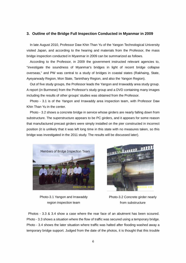
Photo - 3.1 is of the Yangon and Irrawaddy area inspection team, with Professor Daw
Khin Than Yu in the center.
Photo - 3.2 shows a concrete bridge in service whose girders are nearly falling down from
substructure. The superstructure appears to be PC girders, and it appears for some reason
that manufactured precast girders were simply installed on the pier constructed in incorrect
position (it is unlikely that it was left long time in this state with no measures taken, so this
bridge was investigated in the 2011 study. The results will be discussed later).
Photos - 3.3 & 3.4 show a case where the rear face of an abutment has been scoured.
Photo - 3.3 shows a situation where the flow of traffic was secured using a temporary bridge.
Photo - 3.4 shows the later situation where traffic was halted after flooding washed away a
temporary bridge support. Judged from the date of the photos, it is thought that this trouble
Photo-3.2 Concrete girder nearly
from substructure
Photo-3.1 Yangon and Irrawaddy
region inspection team

7
occurred after the inspection team's observation. Subsequently the bridge was apparently
extended in a rush job using a 2-span concrete bridge.
Photos - 3.5 & 3.6 show deformed locker shoes on the Maubin Bridge which spans a
branch river of the Irrawaddy on the Yangon-Pathein road.
Photos - 3.7-10 show the situation of a Bailey bridge and its pipe pier in the Irrawaddy delta
area. Apparently, the pier of a similar bridge collapsed after observation by the inspection
team. This region is prone to seawater intrusion, and it seems that the corrosion of a steel
pipe caused the pier to collapse. Apparently, just after it collapsed, this bridge was
reconstructed as a concrete bridge.
Photo-3.3 Passage of traffic was secured by
using a temporary bridge when the rear face
of an abutment was scoured during flooding
Photo-3.4 Subsequent flooding washed
away the temporary bridge pier and traffic
was halted
Photo-3.6 Deformed shoe of the Maubin
Bridge (2)
Photo-3.5 Deformed shoe of the Maubin
Bridge (1)

8
Photos - 3.11 - 13 and Figure - 3.1 show defective construction work and later repairs to the
upper section of cast-in-place concrete pile of the bridge foundations widely used in
Myanmar.
Photo-3.7 Bailey girder bridge Photo-3.8 Structure of the deck
Photo-3.9 Pipe pier
Photo-3.12 Section of poor execution at the pile top
Photo-3.11 Section of poor execution at
the pile top
Photo-3.10 Deterioration of pipe

9
Photos - 3.14 & 3.15 shows a Schmidt Hammer being used in an inspection. Photos -
3.16 & 3.17 show a diver surveying a submerged section of a pile, and the underwater
photography.
Photo-3.13 Repair of pile top
Photo-3.14 Survey using a Schmidt Hammer
Photo-3.16 Survey of pile in the water
Photo-3.14 Survey using a Schmidt
Photo-3.17 Pile in the water
Figure-3.1 Method of repair at a
section of poor execution at the

10
4. Outline of the Bridges Surveyed The main bridges that were inspected in 2010 and 2011 have been rearranged in order of
the construction date.
Table-4.1 Bridges Inspected
No Bridge name Type(Main
bridge)
Completion Span arrangement (Main bridge)
1 Kyaungkong Truss 1989 4×36.58=182.9m
2 Thakhut Concrete
Girder
1991 9×16.5=148.5m
3 Thanlyin Truss with
rail
1993 80×3+(104+112×2)+(112×3)+(112×3)+(112×2
+104)+80×3=1,808m
4 Bayinaung Truss 1994 65.6+(3×123)+65.6=501.1m
5 Myaungmya Suspension 1996 39.6+182.9+39.6=262.1m
6 Maubin Truss 1998 (4×120)=480m
7 Bomyatun Truss 1999 96+(3×120)+(4×120)+(4×120)+(3×120)+96=
1872m
8 Yar Yamaung Suspension 1999 304.8m
9 Da let- Chaung Bailey 1999 301.8m
10 Aungzaya Cable
Stayed
2000 140.8+300+140.8=581.6m
11 Mahar
Bandoola
Cable
Stayed
2000 55+130+55m=240m
12 Shwe Pyithar Truss 2001 84 + 120×3 +84=528m
13 Min Chaung Truss 2006 (64+84+64)=212m
14 Lonedawpauk Truss 2004 35+60+35=130m
15 Pathein Suspension 2004 86+255+86=427m
16 Min Kyaung
Chaung
Truss 2006 (3×35)+60+(3×35)=270m
17 Twantay Suspension 2006 80.8+263.3+80.8=424.9m
18 Dagon PC
Cantilever
Girder
2007 27.4+(48.8×16)+27.4=835.6m
19 Tha Yu-Pa-PA
done
Suspension 2010 122m

11
1)Kyaunkong Bridge
The Kyaungkong Bridge completed in 1989 is one of 11 small-to-mid sized truss bridges
along the Yangon-Pathein road. The Yangon-Pathein road was improved in the 1980s with
Swiss assistance and technical guidance (Photo 4.1). The superstructure trusses of these
bridges were purchased from an Australian manufacturer.
Photo-4.1 Kyaunkong Bridge
The concrete slabs of this truss bridge were designed under Swiss technical guidance.
Though the lower section of the slabs uses 3.5 inch thick precast concrete members with
tensile longitudinal rebars placed within, there was no particular consideration of integration
with the cast-in-place concrete section on top.
While it is thought that this type concrete slabs cannot withstand substantial repetitive
loading by heavy vehicles, no particular signs of deterioration have been seen as yet (Photo
4.2).
Concrete slabs of the same design were also used in the truss bridges constructed on
Kyaukphyu Island at the beginning of 2000. In this region seawater was used for concrete
mixing, so these concrete slabs sustain massive damage (See Photo-4.76)
.
Photo-4.2 Concrete slab of Kyaunkong
Bridge

12
2)Thakhut Bridge
The Thakhut Bridge is a prestressed concrete girder bridge constructed in 1991 in the delta
(soil in this area is very soft when compared to the Irrawaddy delta) of the Yangon opposite
shore side of Yangon City, and a girder of this bridge noted in the 2010 report was nearly
falling from the bridge substructure (Photos 4.3 -5).
Photo-4.3 Thakhut Bridge
Figure 4.1 shows the general view and photos before and after widening of the top of the
pier (the general view was drawn in the opposite direction to the direction the photos were
taken).
Photo-4.4 Concrete girder nearly falling
from substructure Photo-4.5 Temporaly installed support

13
The abutment of the Yangon side moved forward substantially when the rear embankment
of the abutment was filled, and in response, a 2-span concrete girder bridge was extended
on the Yangon side.
When an abutment moved during construction and a concrete girder was nearly falling
from the central pier, as noted in the 2010 survey report, naturally the pier top would have
been widened at that time. Similarly, the pier is rather far from the abutment so it is unlikely
that this pier moved when the abutment moved.
So, why did this pier move later? This was considered as follows.
Compared with the Irrawaddy region, this region is a soft delta area, and is an estuarine
basin with a large tidal range. For this reason, there is a fairly rapid daily up and down flow in
this area, and the river channel moves easily (rivers meander dramatically in delta areas,
and many river-bed lakes are also seen).
The river channel around this bridge section has moved in these 20 years after
construction, and the riverbed level changed also. In other words, it is believed that the
elevated riverbed caused lateral flow of soft ground soil and the pier above was moved.
If the PW staff had showed concern over the movement of this abutment during
construction and after and continued to measure the bridges behavior, they might have
noticed the bridge substructure on the soft soil would move easily, and they would have
likely been able to minimize any similar trouble occurring later. No doubt this is a harsh
words for the PW that has been pursuing new bridge construction work.
Figure-4.1 General view and Photos(before and after)

14
3)Thanlyin Bridge
The Thanlyin Bridge is a road-rail bridge over the Bago River in south-eastern Yangon, and
was completed in 1993 with grant assistance from China (Photos 4.6 & 7). The structure is
one of a single railway track with two roads either side, and a pipeline.
In contrast to later bridge construction in Myanmar, the bridge was constructed by the
assistance of the Chinese government and carried out almost entirely by a Chinese
workforce.
The bridge was maintained by the Ministry of Rail Transport, and though nearly 20 years
have elapsed since it came into service, the bridge appears to have been relatively well
maintained.
Photo-4.7 Thanlyin Bridge
Photo-4.6 Thanlyin Bridge

15
4) Bayinaung Bridge
The Bayinaung Bridge was constructed in western Yangon and was the first erected over
the Hlaing River. It is a two-lane truss bridge (Photo 4.8, fig. 4.2).
Soil condition in this area is typically of soft layers (Fig. 4.3), and the Yangon opposite
abutment has been pushed forwards due to earth pressure on its rear embankment and
gave compressive force on the truss superstructure. In 2003, large-scale repairs work was
done by suspending the traffic.
Photo-4.8 Bayinaung Bridge
Figure-4.2 General view of Bayinaung Bridge

16
Figure-4.3 Boring log of the Bayinaung Bridge
Photo 4.9 shows a movable shoe on the Yangon side of which bearing plate was
elongated. The shoe on the opposite shore side, as shown in Photo 4.10, appears to be
functioning comparatively soundly.
As for the expansion joints on both sides, the teeth began to collide so in response the claw
was cut during large-scale repairs. However, at present the gap of the expansion joint has
disappeared (Photo 4.11), and partial fractures can be seen in some sections (Photo 4.12).
So it is thought that the abutment is still moving and countermeasures would be required.
Photo-4.9 Movable shoe (Yangon side)

17
Photo-4.10 Movable shoe (Yangon opposite shore side)
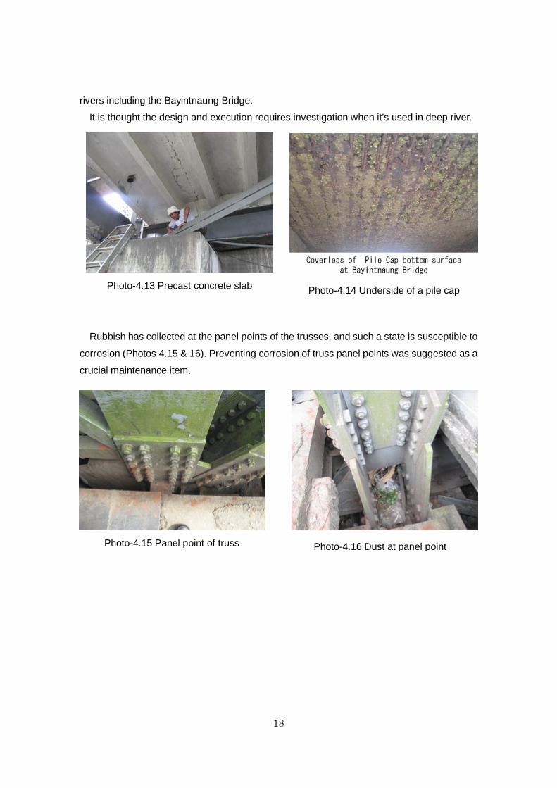
Photo 4.13 shows a precast concrete slab. This precast slab is reinforced with longitudinal
ribs, and there appears to be no problems with the strength of the joints.
Photo 4.14 was taken at the time of the full inspection in 2009 and shows the situation of
the underside of the top slab (known as a "pile-cap" within PW) supporting the bridge pier.
The rebars are exposed.
The type of pier foundation used in the Nguwun Bridge which was constructed as a
follow-up project of the BETC(The pier is supported on the pile-cap supported by the cast- in
place concrete piles projected from riverbed) is used in construction over Myanmar's large
Photo-4.12 Expansion joint
(Yangon opposite shore side)
Photo-4.11 Expansion joint
(Yangon side)
18
rivers including the Bayintnaung Bridge.
It is thought the design and execution requires investigation when it’s used in deep river.
Rubbish has collected at the panel points of the trusses, and such a state is susceptible to
corrosion (Photos 4.15 & 16). Preventing corrosion of truss panel points was suggested as a
crucial maintenance item.
Photo-4.13 Precast concrete slab Photo-4.14 Underside of a pile cap
Photo-4.15 Panel point of truss Photo-4.16 Dust at panel point

19
5)Myaungmya Bridge
The Myaungmya Bridge is a suspension bridge constructed in the center of the Irrawaddy
delta in 1996 (Photo 4.17).
An abutment of this bridge moved forward while erecting the main cable, the embankment
on the rear face of the abutment was changed to a concrete bridge in order to eliminate
earth pressure from the rear face of the abutment, and piles were cast around the abutment
as a countermeasure. Photo 4.18 shows the abutment on the south side. The top of the
main tower was moved over 1m, and the inclination of the main tower can be seen in Photo
4.19.
Apparently the bridge manager was also unsure of the strength of this bridge, and has
restricted the two-lane flow of traffic to a single lane using a line of rocks on the road surface,
as can be seen in Photo 4.20.
Photo-4.18 Anchorage (south side)
Photo-4.19 Inclined tower Photo-4.20 Rocks put on the road surface
Photo-4.17 Myaungmya Bridge

20
The connection between the main cable and hanger has been corrosion proofed using a
material thought to be cement mortar and as shown in Photo 4.22, the main cable has
simply been passed straight through the flooring. The road surface is comprised of I-type
steel, and as can be seen from Photo 4.23, a simple expansion joint was used between
abutments.
There are concerns over the durability of all the above and it was suggested that this bridge
needs to be maintained while keeping in mind all these concerns.
Photo-4.22 Cable passes through the
road surface
Photo-4.23 Expansion joint
Photo-4.21 Corrosion proofing by
cement mortar?

21
4)Maubin Bridge The Maubin Bridge was completed in 1988 in a region of soft soil within the Irrawaddy delta
belt, and the bridge's shoes are greatly deformed (Photo 4.24, figs. 4.4 & 5).
Photo-4.24 Maubin Bridge
Figure-4.4 General view of Maubin Bridge

22
Figure-4.5 Boring log of the Maubin Bridge
In the same way as with the Bayinaung Bridge, the abutment that sits upon soft soil has
moved forward due to earth pressure on its rear face, and this is thought to put pressure on
the truss superstructure.
Photo 4.25 shows that the rubber shoe of the approach concrete bridge atop of the truss
bridge's end pier has been severely shear deformed, and we can see that the pier has been
pushed from the concrete bridge side.
Photo-4.25 Rubber shoe subject to major shear deformation
As shown in Photos 4.26 & 27, the main body of the locker shoe is greatly deformed, and

23
on the Maubin side the stopper of the lower shoe has become detached.
Likewise, Photos 4.28 & 29 show the expansion joint and parapet atop the abutment of the
approach concrete bridge, and it is clear that earth pressure is acting on the rear face of the
abutment.
This bridge also uses precast concrete slabs, though there are concerns about its durability
since prestress has not been introduced into the cast-in-place concrete joint between the
precast slabs (Photo 4.30).
Photo-4.30 Precast concrete slab
Photo-4.28 Expansion joint (Maubin side)
Photo-4.26 Shoe (Yangon side) Photo-4.27 Shoe (Maubin side)
Photo-4.29 Abutment (Maubin side)

24
7)Bomyatun Bridge
The Bomyatun Bridge is a truss bridge completed in 1999 over a branch river of the
Irrawaddy on the Yangon-Pathein road, and was Myanmar's longest bridge at the time
(Photos 4.31 & 4.32).
Though the 2010 survey detected rust at the truss panel points (Photo 4.33), no other
degradation damage was found.
Photo-4.33 Rust at the panel point of the truss
In the 2011 survey, since damage was detected in some of the asphalt pavement surface,
looking at the underside of the slabs revealed evidence of repair to the slabs (Photos 4.34 &
35).
Photo-4.31 Bomyatun Bridge Photo-4.32 Bomyatun Bridge

25
Photo-4.34 Damaged asphalt pavement
Photo-4.35 Remnants of repairs to concrete slabs

26
8)Yar Yamaung Bridge
The Yar Yamaung Bridge is a single-span suspension bridge completed in 1999 (Photo
4.36).
Photo-4.36 Yar Yamaung Bridge
Due to the low traffic volume over this bridge, even though there are two lanes, most
vehicles drive down the center of the road which has caused the molded steel of the road
surface to become deformed (Photo 4.37). It would be preferable if small blocks (chatter
bars in Japan) were installed along the center line to ensure the traffic to keeps the two-lane
system.
Photo 4.38 shows what appears to be a cement mortar coating to the main cable. The
same kind of material was used on the Myaunmya Bridge in the Irrawaddy region surveyed
Deformation of steel deck

27
in 2010. It was a surprise such a low quality coating was used in this bridge also. We
thought the Myaunmya Bridge was an exceptionally low quality suspension bridge because
of the very first suspension bridges built in Myanmar.
The coating of the cable has split, been chipped away, and corrosion can be seen on the
exposed inner section of the cable. From the condition of the cable corrosion, the cable may
not have been corrosion proofed (Photo 4.39).
Photo-4.38 Main cable cladding
Photo-4.39 Splitting and erosion of main cable cladding

28
9)Da let-Chaung Bridge
The bridge is a Bailey Bridge constructed in 1999, and is currently under repair since
flooding washed away a pier in 2011 (Photo 4.40).
It appears that the open-caisson foundations were insufficiently embedded into the soft
rock of the river-bed, and the pier was washed away due to scour.
In order to avoid similar future trouble occurring due to flooding, once the cause has been
sufficiently investigated the bridge should be reconstructed, and measures to prevent scour
of the remaining piers may also be required.
Photo-4.40 Da let-Chaung Bridge under repairing

29
10)Aungzaya Bridge
The Aungzaya Bridge crosses the Hlaing River that flows through western Yangon and was
completed in 2000. It is a four-lane cable-stayed bridge with steel girder trusses, and has a
central effective span of 300m (Photo 4.41).
A drainpipe runs through the trusses from the road surface, but only extends partway (not
clearly shown in the photos). Therefore drainage water runs over the trusses causing rusting
(Photo 4.32 & 43). When maintaining the bridge, careful consideration at the level of design
and construction is required.
The slab uses reinforced concrete precast slabs (Photo 4.44).
In Myanmar, due to the strict construction period required, precast slabs are used on-site
instead of cast-in place reinforced concrete slab. At present no signs of deterioration such
as joint leakage has been found, though the design and detailed structure requires
investigation.
Cracks in the surface of the concrete bridge railings were seen (Photo 4.45). Since these
Photo-4.42 Rust due to drain water from the road surface
f
Photo-4.43 Rust due to drain water from the
road surface
Photo-4.44 Precast concrete slab
Photo-4.41 Aunzaya Bridge

30
cracks were of a pattern commonly seen with alkali-aggregate reactions, it is suggested that
the alkali causing the reaction is investigated.
In the rear face of the abutment, cracks such as in Photo 4.46 were seen. It is suggested
follow-up observation is required.
In April 2011, advice was requested by mail in relation to a damaged expansion joint on
the Aungzaya Bridge, and an investigation was carried out in 2011.
A Chinese manufactured expansion joint (an imitation of a German Maurer joint) had been
used, and as shown in photos 4.47 & 48, most of the beams have fractured and support
beams have simply been loaded on top, and then the beams have jumped out with the
passage of traffic above.
The damage has clearly worsened since PW requested repair advice in April 2011. The
fractured beams have fallen on the top of the pier, and timber has been put in the vacant
space (Photo 4.49).
The site was inspected in June 2011 also, and it was advised it was in a state that would
not be left for even a day longer in Japan. Even though it was suggested that at the very
least the damaged sections of the joints should be covered with steel plating, and that traffic
should be instructed to drive slowly, no action had been taken by the time of the 2011 study
in December that year (when this was suggested again in the 2011 study, the damaged
sections were finally covered with steel plating).
Note that, the same type of expansion joint as used in this bridge was purchased from
China and used in many other truss bridges, and particular care must be taken when
performing maintenance.
Photo-4.45 Cracks in the bridge railing Photo-4.46 Concrete cracks

31
Photo-4.49 Fractured member of expansion joint
dropped on the top of the pier
Photo-4.47 Damage to an expansion joint Photo-4.48 Fractured member of
expansion joint

32
11)Mahar Bandoola Bridge
The Mahar Bandoola Bridge was completed in central Yangon in 2000, and is a six-lane
cable-stayed bridge with a central effective span of 130m (Photo 4.50). Steel trusses were
used in the stiffening girders.
Photo 4.51 shows the attachment zone to the stiffening trusses of the cable. A rubber guard
has been wound around the attachment zone to prevent rainwater seepage; however it has
a major fracture and is not fulfilling its essential function.
The concrete slabs of the approach concrete bridge (Photo 4.52) have been damaged
several times a year over the past few years. Photo 4.53 shows the repairs to the slabs.
When examining the cause of the damage to the slabs, necessary countermeasures need
to be investigated.
Photo-4.50 Mahar Bandoola Bridge
Photo-4.52 Approach concrete bridge of
Mahar Bandoola Bridge
Photo-4.51 Wound cable rubber guard
Photo-4.53 Slab under repairing

33
12)Shwe Pyithar Bridge
The Shwe Pyithar Bridge is a four-lane truss bridge completed in 2001 and crosses the
highest reaches of the Hlain River (Photo 4.54).
Photo-4.54 Shwe Pyithar Bridge
No major deterioration damage was seen in the superstructure of this bridge, though the
main members of the truss and panel points have rusted (Photo 4.55 & 56).
There were sections of untended damage to the expansion joint (Photo 4.57).
At the slab of the approach concrete bridge, due to shortening the construction period, a
left-in-place material precast concrete formwork has been used on the underside of the
slabs (Photo 4.58).
Photo-4.55 Rust of the truss Photo-4.56 Rust of the panel point

34
13) Min Chaung Bridge
The Min Chaung Bridge is a truss bridge that spans a channel of the eastern Sittwe
marshes (Photo 4.59).
Photo-4.59 Min Chaung Bridge
From looking at the surroundings, no doubt it is difficult to obtain a large quantity of
freshwater, and it appears seawater was used when mixing concrete during the construction
of the bridge. Of course it is thought unwashed sea sand was used as the construction
material.
A large quantity of concrete has peeled away from the concrete pier and the rebars have
become exposed and fractured (Photo 4.60). Due to major peeling of the concrete, one
section has fallen off and smashed (Photo 4.61).
Photo-4.57 Damaged expansion joint Photo-4.58 Slab of an approach concrete bridge

35
The rebars of the peeled insides have corroded and turned a black-red color which is a
characteristic of salt damage (Photo 4.62).
Part of the concrete pier has been reinforced using concrete lining (Photo 4.63).
Photo-4.62 Rebar corrosion and concrete covering
Photo-4.63 Strengthening of the piers of the Min Chaung Bridge using concrete lining
Photo-4.60 Damaged concrete pier Photo-4.61 Fragments of peeled off concrete
around a pier

36
Looking at the corrosion of the steel members, the whole bridge continues to corrode, and
pitting corrosion that gouges deep into the member can be seen. The rust that fell when
cleaning the surface for repainting (Photo 4.64) is characteristic of salt damage, and paint
film degradation and steel corrosion due to airborne salt and salty air were confirmed (Photo
4.65).
Not only is the number of coats applied in the repainting insufficient, with just one coat each
of primer and anti-corrosive paint, (four or more coats are standard in Japan), but the
anti-corrosive paint also appears to be one of low-quality that has been discontinued in
Japan, and long service cannot be expected in this environment of salt damage.
There is also no quality control of the paint used for the paintwork, which it seems is simply
painted on with no essential pre-painting survey or control of film thickness. Such a method
will require another repainting sooner or later, and each repainting weakens and significantly
reduces integrity of steel member.
Photo-4.65 Fallen rust fragments Photo-4.64 Repairing work (within the circle are
workers using only a safety rope)

37
14)Lonedawpauk Bridge
The Lonedawpauk Bridge is one of ten bridges constructed in the Kyaukphyu region of the
Yangon-Kyaukphyu road completed in 2004. All are of the same design including the Min
Kyaung Chaung Bridge.
This is an area where obtaining a large quantity of freshwater is no doubt difficult and it is
thought seawater was used in concrete mixing. The execution of the concrete is also not
good (Photo 4.66 & 67)
Photo-4.66 Underside of an approach concrete bridge's walkway
Photo-4.67 Cross beam of an approach concrete bridge

38
As seen in Photo-4.68, deterioration of slab has been already started.
Photo-4.68 Depression in a road surface due to damaged slabs
Looking at the corrosion of the steel members, as can be seen in photos 4.69 & 70, peeling
of the paint film on the truss members can be seen over a wide area. Peeling of the paint
film suggests that the paint itself has low adhesive properties, and the cause of the peeling
requires investigation since the total destruction of paint film is regarded as a warning.
In some areas of peeling the film thickness is less than half, and since the
anti-corrosiveness of those areas is greatly reduced, repainting (recoating) is urgently
required as soon as the cause of the peeling is found.
Photo-4.69 Peeled paintwork of the truss
Photo-4.70 Peeled paint film

39
15)Pathein Bridge
The Pathein Bridge constructed in 2004 is a suspension bridge of a similar scale to the
Twantay Bridge manufactured by the same Chinese manufacturer (Photo 4.71, fig. 4.6 & 7).
Photo-4.71 Pathein Bridge
図-4.6 General view of Pathein Bridge

40
Figure-4.7 Boring log of Pathein Bridge
Almost exactly the same problem was found on the Twantay Bridge constructed in 2006.
In addition, fractured high-tension bolts due to what was believed to be delayed fractures
were seen not infrequently (Photo 4.72). It is suggested that in order for future
countermeasures to be taken, bolt quality should firstly be tested, and the bridge's
manufacturer should be informed to consider future countermeasures.
Photo-4.72 Deficit of bolt at truss splice plate
41
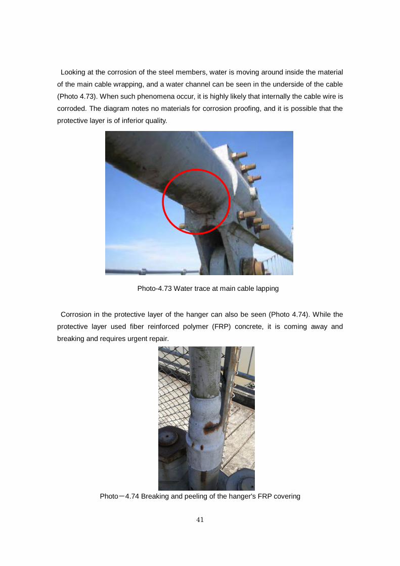
Looking at the corrosion of the steel members, water is moving around inside the material
of the main cable wrapping, and a water channel can be seen in the underside of the cable
(Photo 4.73). When such phenomena occur, it is highly likely that internally the cable wire is
corroded. The diagram notes no materials for corrosion proofing, and it is possible that the
protective layer is of inferior quality.
Corrosion in the protective layer of the hanger can also be seen (Photo 4.74). While the
protective layer used fiber reinforced polymer (FRP) concrete, it is coming away and
breaking and requires urgent repair.
Photo-4.74 Breaking and peeling of the hanger's FRP covering
Photo-4.73 Water trace at main cable lapping

42
16)Min Kyaung Chaung Bridge The Min Kyaung Chaung Bridge was completed in 2006 (Photo 4.75).
Photo-4.75 Min Kyaung Chaung Bridge
Since seawater was apparently not used in the concrete mixture for this bridge, the
concrete of the piers, etc., is relatively sound.
However, as for the concrete slabs of the truss section, as shown in photo 4.76, the
covering concrete of the concrete precast slabs used for the underside of the slabs is falling
away. This is thought to be because seawater was used in the manufacture of the precast
slabs.
Photo-4.76 Damaged precast concrete slabs
43
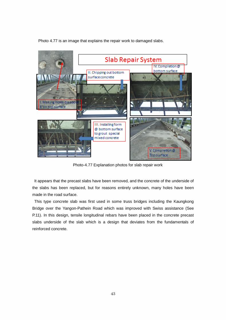
Photo 4.77 is an image that explains the repair work to damaged slabs.
It appears that the precast slabs have been removed, and the concrete of the underside of
the slabs has been replaced, but for reasons entirely unknown, many holes have been
made in the road surface.
This type concrete slab was first used in some truss bridges including the Kaungkong
Bridge over the Yangon-Pathein Road which was improved with Swiss assistance (See
P.11). In this design, tensile longitudinal rebars have been placed in the concrete precast
slabs underside of the slab which is a design that deviates from the fundamentals of
reinforced concrete.
Photo-4.77 Explanation photos for slab repair work

44
17)Twantay Bridge
The Twantay Bridge constructed in the Yangon suburbs in 2006 is a single-span
suspension bridge of almost the same scale as the Pathein Bridge constructed in 2004. The
superstructure was purchased from a Chinese manufacturer (Photo 4.78, fig. 4.8).
Photo-4.78 Twantay Bridge
Figure-4.8 General view of Twantay Bridge
This region has soft alluvial ground as shown in Figure. 4.9.
This suspension bridge has lost a great deal of camber since completion, and in the 2010
study it was suggested that because the anchorage has simply been laid on the
cast-in-place concrete piles (diameter of 1.2m), the horizontal force of the main cable may
move the anchorage forward.
H5 D5

45
Figure-4.9 Boring log of Twantay Bridge
From looking at the ground surface layer surrounding the anchorage (Photo 4.79), the gap
of the expansion joint of the approach concrete bridge (Photo 4.80), and the concrete
peeling off the cross beam of the pier below (Photo 4.81), the change in camber is believed
to be mainly due to the movement of the anchorage.
The behavior of the suspension bridge needs to be measured urgently, and depending on
the results, countermeasures may be needed to prevent the anchorage from moving.
Photo-4.79 Gap between the main tower
and the ground behind Photo-4.80 Gap of expansion joint 5

46
Photo-4.81 Concrete peeling of the cross beam of the H5 pier
As indicated in photo 4.82, the hanger rope and truss top chord are joined with bolts,
though the bolt-heads are corroding. It is suggested that drainage holes are urgently bored
in the truss and the bolts are anti-corrosion proofed (it was also suggested in the 2010
survey to bore drainage holes, though this has not been implemented).
Similarly, as shown in Photo 4.83, the truss top chord is seriously corroded, so it is
suggested that similar anti-corrosion proofing is required, and a creasing structure (water
cutting structure) is proposed for the underside of the end of the slabs.
Photo-4.82 Corrosion of the hanger rope
attachment
Photo-4.83 Corrosion of the top truss chord

47
18)Dagon Bridge
The Dagon Bridge completed in 2007 is a six-lane concrete Gerber bridge of a total length
of over 800m which spans the Bago River in eastern Yangon (Photo 4.84 & 85).
This is one of the few long-span concrete bridges because Myanmar has strict demands in
relation to construction periods. There were also problems in providing cement and it took
7-8 years to complete. A mainline to connect the new port and new industrial zone in central
Yangon and eastern Yangon is under construction, though it is thought because the
Thanlyin Bridge described above is located slightly downstream, only a low volume of traffic
is expected for the time being, and hence a concrete bridge was adopted.
There are fears that damage will appear in the near future as the Gerber construction has
multiple expansion joints which will vibrate severely with the passage of heavy trucks.
Photo-4.85 Still less traffic Photo-4.48 Same type bridge as Dagon Bridge

48
19)Tha Yu-Pa‐PA done Bridge
Photo 4.86 shows a newly completed suspension bridge in the suburbs of Ann City.
Photo-4.86 Tha Yu-Pa‐PA done Bridge
Though it is small-scale, it is of PW's own design and was constructed of ordinarily
available materials with the exception of the main cable which was purchased from a
Chinese manufacturer.
However, the cable appears to have been coated using the same cement mortar as the
Myaungmya Bridge over the Irrawaddy.
Similarly, the molded steel surface used for the bridge slab has no checkers (hatched
markings), and it is feared that 2-wheeled vehicles may slip (checkers are generally used on
this kind of molded steel bridge slab, but apparently it just happened that none were
available when this bridge was constructed. Perhaps this was due to the strict construction
period).

49
5. Main issues 1)Salt damage to concrete
Along the Bengal coast of Rakhine Region, the westerly wind from the Bay of Bengal
brings high-temperatures and humidity and so concrete structures sustain remarkable salt
damage.
However, in addition to such unfavorable conditions, the lack of basic measures against
salt damage to concrete cannot be overemphasized.
Figure-5.1 Bengal Bay in Myanmar
More specifically, on the islands off the coast in this region, securing a large volume of
freshwater is difficult so it is thought that not only has unwashed sea sand been used, but
seawater has been used to mix concrete in parts of the site. Needless to say, if seawater is
used to mix reinforced concrete, there will be significant salt damage to the concrete. Use of
seawater must be totally prohibited.
Likewise, if using sea sand, it must be washed in freshwater as a rule. If washing sea
sand is difficult due to difficulty in securing a large volume of freshwater, a mound of sea
sand should be sufficiently exposed during the rainy season and then used when the top
layer of sand is confirmed to be below the standard level of salt concentration
Similarly, when designing with reinforced concrete, while it is only natural that sufficient

50
concrete covering must be secured, it is also necessary to consider introducing
anti-corrosive technology such as rebars with epoxy paint.
At any rate, the reality that seawater has been used to mix concrete must be faced, and
strict approaches to counter salt damage to concrete are essential.
Similarly, concrete structures that are already seriously salt damaged must urgently be
repaired and reinforced.
While it appears that some repair work is already underway, such work should not be
carried out based on the judgment of individual supervisors, but must be approached
through the organization of the PW.
2)Design of concrete slabs for bridges
In Myanmar, precast concrete panels are often used for the slab of bridges due to
workability and short constructed periods.
These are shown below.
Type I is commonly used in concrete girder bridges (Photo 5.1, fig. 5.2). It uses precast
panels only as formwork, and precast panels are ignored in the calculation of cross sectional
strength. In this case, the cast-in-place concrete slabs are six inches thick, and it is feared
that the cross-sectional thickness is insufficient depending on loading conditions.
Photo-5.1 Slab of concrete girder bridge (Type Ⅰ)

51
This type of slab is used on the Mahar Bandoola Bridge which carries a high volume of
traffic within Yangon City, and apparently slabs have been falling frequently in recent years.
Type II is a precast slab with ribs attached and is used on the Bayinaung Bridge (Photo 5.2).
It is of sufficient rigidity and no anomalies were seen in the joints, etc.
The trusses for this bridge are made by an Italian manufacturer, and this bridge is the only
bridge using this type of slab.
Figure-5.2 General view of Type Ⅰ
Photo-5.2 Slab of Bayinaung Bridge (Type Ⅱ)

52
Type III is a precast slab which is used on most truss bridges by Chinese manufacture and
also by Japanese corporations (Fig. 5.3, photo 5.3).
Figure-5.3 General view of Type III slab
Photo-5.3 Precast slab of a general truss bridge (Type III)
While there are concerns over the durability of the cast-in-place concrete joints (prestress
is not introduced) of the precast slabs, currently no signs of deteriorated joints have been
seen.

53
However, since there are concerns that the joints will be damaged in the long-term, at
some point it is thought countermeasures must be considered.
Type IV is the slab used in a small-to-midsize truss bridge when the Yangon-Pathein Road
was improved with Swiss assistance in the 1980s (Photo 5.4 & fig. 5.4).
Photo-5.4 Type IV slab

54
Figure-5.4 General view of Type IV slab
This slab is composed of cast-in-place concrete on top of precast panels arranged on the
cross beam of the truss floor system; however, the precast panels contain tensile
longitudinal rebars.
Looking at the design documents, it became clear that the designer had no understanding
whatsoever of the principles of reinforced concrete. The explanation of the design of the
slabs is as follows.

55
If no cracks appear in the concrete, the rebar stress created by ordinary loading would be
very small. It has to be said that the design deviates from the principles of reinforced
concrete.
There has also been no consideration of the integration of the precast plates and
cast-in-place concrete.
The PW engineers feel the manufacturer is partly responsible for the superstructure of the
slabs, and did not have doubts about the design.
However, regardless of how it was designed, the vehicle load is currently low, and because
no tension cracks have appeared in the concrete, there are no particular visible
abnormalities.
Since there is currently no visible damage, it is difficult to take countermeasures, but if the
volume of traffic and heavy vehicle traffic increases, life-threatening damage will certainly
occur, and some kind of action is required.
Concrete slabs designed in the same way are used on ten truss bridges on the
Yangon-Kyaukphyu Road in the Kyaukphyu region (this method was also adopted for the
approach concrete bridges within this group of bridges). However, seawater was used in the
concrete of the precast members in this region, so the rebars in the precast members have
corroded and the underside of the concrete started to fall away, and serious damage to the
slabs has already occurred.
It is thought there is no better repair method than to replace the single-piece cast-in-place
reinforced concrete slabs.
(This was revealed after leaving Myanmar from available data that this type of slab was
used on an approach concrete bridge of the Maubin Bridge designed in 1996. That means

56
apparently this type of concrete slab is used rather extensively in Myanmar).
Type V is used in suspension bridges of relatively recent construction, and is a longitudinal
precast slab supported by the crossbeam of the stiffening trusses as (Photo 5.5, fig. 5.5).
Photo-5.5 Type V slab
Figure-5.5 General view of Type V slab
At present it appears to be in a sound state, with no anomalies seen in the longitudinal
masonry joints of the precast slabs.

57
However, the way of calculating the cross-sectional force of the design needs to be verified
since the effective span length of this concrete slab is greater than general flooring.
Above, each type was described, and Type IV needs to be discontinued immediately, and
there are also doubts about any future usage of Type III.
At any rate, the design of the concrete slab of bridges should not be left to the bridge
manufacturer, and since damaged slabs present an immediate obstacle to traffic. PW must
make a concerted effort to address the challenges of the future design, construction,
maintenance and repair of concrete slabs.
The fundamental thinking on the deterioration of bridge slab is as below
The damage to the concrete slab is caused by alternating shear stress by repeated wheel
loading exerted on the concrete cross-section in which the cracks occur (Fig. 5.6), and the
concrete in-situ joint of the Type III slabs is at risk of damage for the reasons described (Fig.
5.7).
With the Type IV slabs, when cracks appear in the concrete, major stress is exerted on the
face between precast panel and cast-in-place concrete and the bond between them must be
damaged by the repeating traffic load, and the integrity of the precast panel and
cast-in-place concrete is lost and it is no longer able to function as slab (Fig 5.8).
Figure-5.6 Cause of the deterioration of concrete floor slab of the bridge
Asphalt
Crack
Concrete Slab
Movement of the Wheel

58
Figure-5.7 Deterioration of the in-situ joint of a Type III slab
Figure-5.8 Deterioration of the in-situ joint of a Type IV slab
Asphalt
in-situ concrete joint
Precast member
cross beam
8 in
ch
before concrete cracking after concrete cracking
Precast member
in-situ concrete slab Asphalt
3.
5 in
ch
concrete crack
In-site joint
Precast member
in-situ concrete
Tensile bar

59
Note that in Japan, to prevent damage to concrete bridge slab due to vehicle loading, the
level of allowable stress on rebars is set lower than other structures to prevent major cracks
appearing in the concrete, and regulations are in place stipulating that slabs should be of
minimal thickness to minimize shear stress on concrete.
3)Movement of bridge substructures on soft ground
Table 5.1 is a timeline of cases of bridge substructures thought to have moved atop soft
ground.
Table-5.1 Case where a bridge's substructure is believed to have moved due to soft soil
No Bridge Completion
1. Thakhut Bridge 1991
2. Bayinaung Bridge 1994
3. Myaungmya Bridge 1996
4. Maubin Bridge 1998
5. Pathein Bridge 2004
6. Twantay Bridge 2006
Case 1 is an early phase concrete bridge that PW constructed after BETC, and the
abutment was moved during construction due to the embankment at the rear face of it and
also the pier was moved by the change in the height of the river bed. In cases 2 & 4, the
abutment on the soft ground moved forward due to earth pressure on its rear face and had
negative effect on the truss bridge, and cases 3, 5, & 6 are cases where the anchorage of a
suspension bridge is believed to have moved due to horizontal force by the main cable.
In other words, in Myanmar, regardless of the numerous experiences of substructures
moving easily atop soft ground due to horizontal force, almost no action has been taken.
During the current study, we were able to make the PW engineers realize that bridge
substructures move easily on soft ground. In particular, if the movement of a suspension
bridge's anchorage does not stop, there is even a risk of bridge collapse.
Likewise, in the wide-ranging area of the Irrawaddy delta, countermeasures against the soft
ground are a major issue for the PW engineers who are attempting to build a road network
of over 800km in this region to respond to Cyclone Nargis.
4)Repairs to the expansion joints and shoes of bridges
Most of the damage to the expansion joints and shoes of bridges were thought due to the

60
movement of the bridge substructures. It is thought that the expansion joints and shoes,
aside from whether they are functioning satisfactorily can be reused, as many are made
from relatively sound materials. However, it is difficult for the PW staff to investigate repair
methods since there are no bridge general views or design calculations which are required
when considering repair designs. Though currently there are few engineers related to repair
because efforts are still directed to construction, it is thought emphasis must be put on
acquiring repair skills so that the same damages do not recur. Similarly, regarding each type
of repair work, it is thought that the details of repairs must be recorded so that a response
can be taken when the same kind of damage appears. Bearing in mind that infrastructural
improvements are progressing, and that Myanmar is entering an age where bridges will be
increasingly extended and continue to age, it must be recognized that a database needs to
be built to record the various bridge specifications and details of repair works.
The Chinese manufactured expansion joint installed on the Aungzaya Bridge has been
used on many long-span bridges that were designed in China such as the Maubin Bridge,
and the design details of this expansion joint are not understood. It was recommended
bridges installed with this expansion joint should have the device replaced with a finger joint
because PW can understand the structure and domestic manufacture is possible.
The design calculations for the bridge design are based on Japan's standard for bridge
design, and PW also has the design materials for part of the finger joint (though apparently
they have never calculated it themselves), and it is thought with experience they will become
able to design expansion joints. However, PW has no experience of repair work to replace
expansion joints, and it is hoped that they can receive guidance while referring to cases of
repair work performed in Japan.
Regarding bridge shoes, damage to the Maubin Bridge's locker shoes and rubber shoes
was seen, and damage was also seen on all shoes where displacement in a horizontal
direction exceeding the anticipated change in position had been applied to the main body of
the shoe. When changing bridge shoes such as the locker shoes of the Maubin Bridge, it is
thought that replacement by jack-up is common, but the reinforced structure of the girders
and jacking-up process must be sufficiently understood before this is carried out. In
particular, with concrete girders, if it is not jacked-up simultaneously and equally, the main
bridge may be damaged. It is hoped that technical support will also be provided with such
repair work.
5)Bridge paintwork
It is common knowledge that the paint on coastal steel bridges is susceptible to damage
from the salty air. In Myanmar, in terms of damage to steel bridges, corrosion of the overall

61
bridge is seen within ten years, and the need for repainting is pressing.
However, if repainted using the same poor quality paint, it makes matters worse. Paint with
a superior anti-corrosive effect must be adopted.
One of the reasons for the early deterioration of paintwork is the problem with the quality of
bridge paint. There are many reasons why the paintwork is of poor quality, including the lack
of reliable specifications, poor quality paint, defective execution, and the inadequate system
of acceptance testing and inspection.
Looking at the paintwork of the steel bridges in Myanmar, the reality in every case is of
insufficiency or total lack of implementation.
First of all, while an appropriate paint selection is fundamental to improving paintwork
quality, paint is an organic material that deteriorates easily in sunlight, while some paints
also weaken in high-humidity. For this reason, paint needs to be durability tested when
selecting paint to the climate in Myanmar.
Similarly, appropriate quality control is essential because paintwork quality varies easily
depending on the level of the work performed.
Furthermore, when maintaining paintwork, it is preferable that lifecycle costs are minimized
through regular inspection and repainting before corrosion becomes severe.
The corrosion of suspension bridge cables also presents a serious issue. This time, while a
detailed survey was not possible, it is thought anti-corrosion methods and cable protection
methods must be totally improved.
6)High-tension bolts
The damage to the high-tension bolts was found on the Pathein Bridge. It may have been
resulted from delayed fracture which can cause sudden brittle fracture of bolts, even without
the exertion of an external force on them and fatigue fracture by repeated loading and
ductile fracture by excess loading.From inspecting the fractured surface of a bolt, it is
possible to judge whether the damage resulted from delayed fracture or from fatigue fracture
from repeated loading, or ductile fracture due to excess loading. Delayed fractures occur
particularly easily the stronger the steel, and in case of high-tension bolts, it is known that
occurrence is pronounced if the tensile strength of the steel exceeds 1,200N/mm2. Due to
this, it is recommended that the cause of the bolt fracture is inferred by examining the tensile
strength and fractured surface of the bolt.

62
Photo-5.6 Types of fractured surfaces of bolts
Likewise, it is also recommended to prevent any fracture of high-tension bolts by using an
inspection hammer. They are to check for abnormal tactile sensations with the fingers,
sounds and vibrations in all the bolts manufactured in the same batch as the damaged bolt,
or all bolts in the same section of the joint (splice plate) as the damaged bolt.
Figure-5.9 Inspection method
7)Other issues
Bridge piers that use cast-in-place piles raised up to water level such as are frequently
used in Myanmar are by no means unproblematic in terms of how these piles are used. As
regards design, however, they are being analyzed for elasticity as projecting piles, and
apparently studies are also under way into horizontal force caused by collisions with ships.
Regarding scour, specific cases from the past need to be verified, and the acquisition of
basic knowledge is required (not even maps were readily available when performing the site
survey of bridges damaged by scour).
Regarding the alkali-silica reaction of the aggregate, though it was said that the concrete
damage in Rakhine State was a contributory factor, no events were observed that
particularly supported this. However, it’s recommended to study on those matters through
the contact with the persons in charge of the dam who have enough knowledge.

63
Appendix
Some new findings from the study [Research Study on Review and Application of the Bridge
Engineering Training Center Project in Myanmar] by JICA, 2012
In Myanmar, 5 big bridges crossing Irrawaddy River have been constructed in these years
and three of them were completed.
One of those bridges, Pakokku Bridge constructed in Middle Myanmar was opened for
service on 31st Dec.2011.
This bridge is a road-rail bridge with 3,484m long main bridge and the steel weight of the
superstructure truss is almost 30,000ton.
Even under the condition of not enough construction equipment and material, this bridge
was completed only in two years including substructure work.
What kind of design and execution was done?
In the construction of the concrete slab of truss bridges, in case of the most popular Type
Ⅲslab(P51), in some bridges, only bottom half concrete of the precast slab was placed on
the ground and the upper half concrete was placed after it was carried on bridge trusses.
This method might have been selected because of the lack of the capacity of the handling
crane. But this method is extraordinarily out of the fundamental of the concrete placing. The
durability of the bridge slab is deeply concerned.
On the background of this concrete slab fabrication, it may have been influenced by the
Type Ⅳ(P52) bridge slab(as mentioned in P54-55, the design idea of this slab is out of the
principle of reinforced concrete) used in Myanmar widely.
And in the approach concrete bridge, in any type of concrete bridges, reinforced concrete
bridge (The main girder is prefabricated), pre-tension pre-stressed concrete bridge,
post-tension pre-stressed concrete bridge, the connection of the precast concrete girder and
cross beam seems extraordinarily simplified.

64

65
Current Situation and Issues of Myanmar’s Bridge Work
NGO Technology Transfer Support Program
Ministry of Land, Infrastructure, Transport and Tourism
Publisher
NPO(Authorized)
Japan Infrastructure Partners
Published Date September, 2012