current practice on foundation design of high-rise ... · current practice on foundation design of...
TRANSCRIPT
- 70 -
LOWLAND TECHNOLOGY INTERNATIONAL Vol. 14, No. 2,70-83, December 2012 International Association of Lowland Technology (IALT), ISSN 1344-9656
CURRENT PRACTICE ON FOUNDATION DESIGN OF HIGH-RISE BUILDINGS IN BANGKOK, THAILAND
K. Amornfa 1, N. Phienwej 2 and P. Kitpayuck 3
ABSTRACT: Assessment was made on the current practice on foundation design of high-rise buildings in Bangkok, Thailand to explore rooms for improvement. An interview survey revealed that the current design practice was dominated by structural engineers. They commonly used the conventional method of analysis, namely the combined stress equation, as well as the plate on springs analysis. The finding from the survey study indicates the current design practice does not encourage an optimal design outcome in term of cost effectiveness. The second part of the study is to explore the benefit in adopting the piled raft foundation design concept. A comparative study on the results of the 3-dimensional finite element (3D FEM) analysis and various analysis methods currently used. The results show that the plate on pile springs method which neglects pile-pile and raft-pile interaction give results significantly different from that of the 3D FEM. The 3D FEM shows that only about 70-80% of total building loads are carried by piles when raft is placed in the stiff clay layer. The number of piles in the piled raft foundation can be significantly reduced particularly if the true piled raft foundation concept is adopted, while the foundation settlement only increases slightly. Keywords: Foundation design, high-rise building, piled raft foundation, three-dimensional finite element method.
1 School of Engineering and Technology, Asian Institute of Technology, THAILAND 2 School of Engineering and Technology, Asian Institute of Technology, THAILAND 3 Engineering Division, Seafco Public Company Limited, THAILAND Note: Discussion on this paper is open until June 2013
INTRODUCTION Bangkok, the capital city of Thailand, has been
witnessing a rapid increase in number of tall buildings construction for the past two decades. Because the city is situated in a vast deltaic plain underlain by a series of thick subsoil layers, the buildings need to be founded on piled foundations to transfer load to soil strata at depth. Typically, tall building in Bangkok required basements for purpose of car park space which is stipulated by law. Therefore, piled foundations start at depths of 10-20 m below the ground surface; and often large numbers of piles located at close spacing are utilized owing to large building loads on relatively small land areas. The design has traditionally followed “piled foundation” concept for which all building loads are to be carried by piles. This traditional foundation design concept of Bangkok was justified when considering the preference of minimizing building settlement and potential gap formation underneath the pile cap in long term resulted from land subsidence phenomenon caused by deep well pumping for ground water supply (Phienwej et al. 2006). However, at the turn of the century, the mitigation measures of Bangkok land subsidence have been much improved, consequently the annual rate of subsidence in the inner
city areas where there will be more tall building development has been much reduced or even ceases. Thus, it may be no longer a wise design approach by ignoring the soil bearing resistance below the large-area pile cap in the design.
Nowadays, the “piled raft foundation” concept has been increasingly advocated and adopted in design of tall buildings in many parts of the world (Poulos and Davis 1980; Randolph 1983; Yamashita et al. 1994; Kachzenbach et al. 2000; Poulos 2001; and de Sanctis and Mandolini 2006) because it has a potential cost-saving and a better control of differential settlement. The design makes use of the soil bearing resistance below the raft together with the load carrying capacity of piles. To ensure continuity of the soil bearing resistance to the raft, the piles are designed at a sufficiently lower safety factor than that normally adopted in the traditional piled foundation design so that settlement of the piles are large enough to ensure consistent contact between soil and raft. However, the magnitude of settlement must be within a tolerable limit of building function and structural safety. With the advance in numerical methodology and tools, the analysis of a piled raft foundation, that was once a complex problem and could not be simply adopted in
- 71 -
Current practice on foundation design of high-rise buildings in Bangkok, Thailand
design practice, now becomes available. Thus the option of piled raft foundation design should be explored.
It is the objective of this study to investigate the benefit of adopting the piled raft foundation concept for foundation design of tall buildings in Bangkok. In the study, firstly the current design practice of piled foundation of tall buildings was reviewed by means of interviews with a group of sampled design firms. In investigation of the application of piled raft foundation in Bangkok area, a 3D FEM analysis using PLAXIS 3D Foundation software (Brinkgreve and Broere 2004) was conducted. PLAXIS 3D Foundation is a rigorous geotechnical code that is capable of analyzing directly soil-structure interactions. A comparative study was then made on the result of the 3D FEM analysis and that obtained from the simplified FEM structural analysis, i.e. Plate on springs modeling, commonly adopted for piled foundation design in Bangkok. SUBSOILS IN BANGKOK
Bangkok is located on the lower Chao Phraya plain,
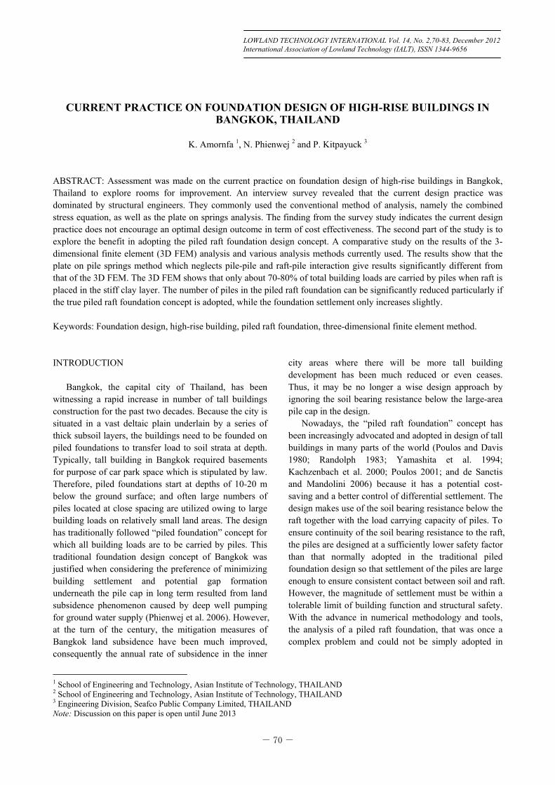
which is made of a very thick deposit of marine and alluvial soils. The subsoil layering is relatively uniform over the entire city area and consists of a 10-15 m thick layer of soft marine clay that is underlain by a very thick series of alternating stiff to hard clay and sand and gravelly sand. The typical subsoil is shown in Fig. 1. Bed rocks are only found at great depths.
Because of the existence of the thick soft clay layer at the ground surface, all buildings in Bangkok are founded on piles to transfer load to soil layers at depth. Various pile depths are used depending on type and size of structures as well as the era of construction as also shown in Fig. 1. Short friction piles (6 to 12-m depth) floating in the soft clay layer were commonly used for old structures. For later period, driven concrete piles or
bored piles with tips extending to the first sand layer at 18 to 30-m depth are commonly employed for light to medium sized structures. For tall buildings, deep large-diameter bored piles with tips extended to the second sand layer (40 to 60-m depth) are usually used. Recently, barrette piles (size 1 m x 2 m to 1.5 m x 3 m) constructed by means of the diaphragm wall technique are also adopted in a few tall building projects where the required working load per pile exceeded 20,000 kN.
Nowadays, there are more than 4,500 buildings exceeding 23-m height and 14 buildings exceeding 200-m height in Bangkok. The number of high-rise buildings has been increasing dramatically in the inner city area. The list of the tallest group of building as of 2012, excluding those under construction, is shown in Table 1. These buildings were mostly designed to have concrete mat slabs to transfer superstructure load to bored piles. The thickness of the slab ranges from 2.5 to 3.5 m, but in some building it reached 5.0 m. From the survey, it was estimated that the cost of piled foundation of these tall buildings was 5-10% of total construction cost. CURRENT DESIGN PRACTICE Design Group and Approach from Interview and Literature Review
Currently, there are about 30-40 tall building design
companies working in Bangkok market. A systematic interview was made with 10 chief/senior engineers of about 30% of total design companies. They have been working on foundation design for high-rise buildings in Bangkok. Interview questions cover issues on interaction between structural engineers and geotechnical engineers, preliminary design, and detail design.
Fig. 1 Typical Bangkok subsoil profile and range of pile length (After Phienwej et al. (2006) and Thasnanipan et al. (2006))
Table 1 List of tallest building with height exceeding 200 meters in Bangkok 2012 No. Building Height Storey 1 Baiyoke Tower II 304 85 2 The River Tower A 266 73 3 Meritus Suites State Tower 247 63 4 Centara Grand Hotel 235 57 5 The Met 228 69 6 Empire Tower 1 227 62 7 Jewelry Trade Center 221 59 8 Amanta Lumpini 212 61 9 China Resources Tower 210 53
10 Thai Farmer Bank Headquarters
208 42
11 Central World Tower 204 45 12 The Pano 202 55 13 Terminal 21 202 42 14 Q-House Lumpini 202 39
- 72 -
Amornfa, et al.
The survey was conducted based on intensive face-to-face interviews with a small number of respondents to explore their current practice. Determination of qualitative sample size relies on the concept of “saturation point” or the point at which no new information or themes are observed in the survey. Based on this survey data, it found that saturation occurred within the first 10 interviews. Variability of the current practice within 10 respondents followed similar patterns.
On the basis of the survey result, the current practice is assessed so that recommendations for improvement can be made to achieve a better engineering practice and economical outcome in future project. Interview group
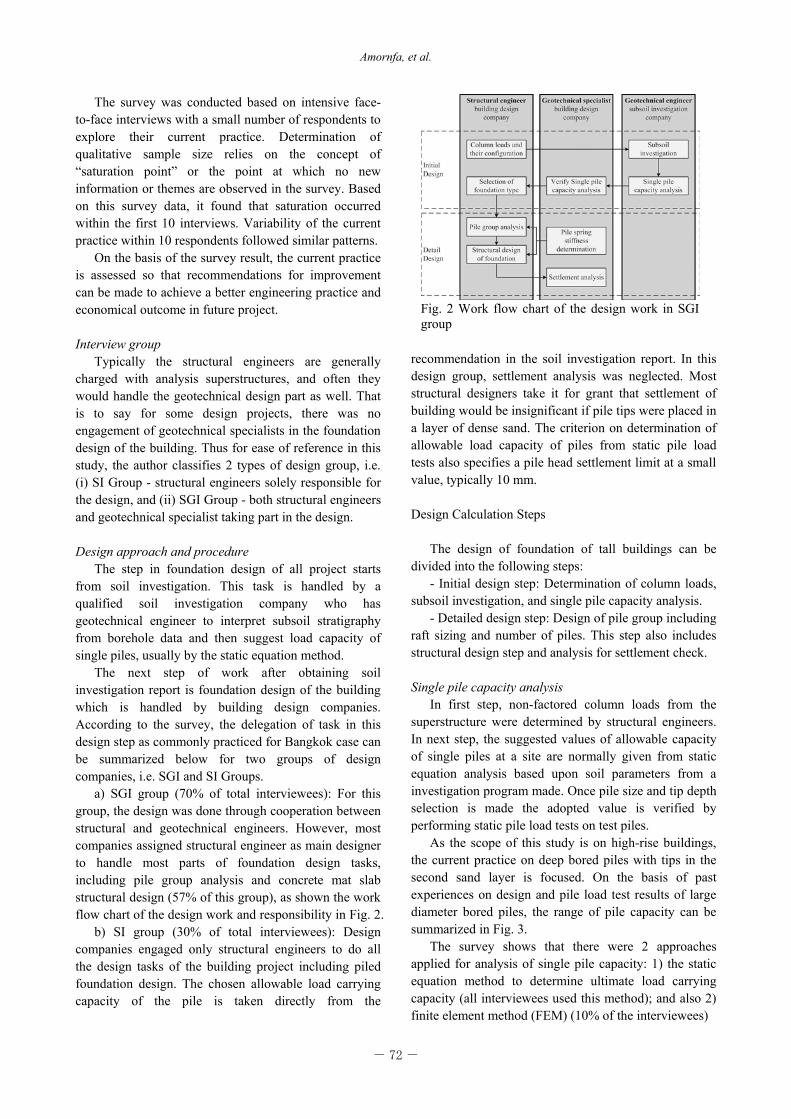
Typically the structural engineers are generally charged with analysis superstructures, and often they would handle the geotechnical design part as well. That is to say for some design projects, there was no engagement of geotechnical specialists in the foundation design of the building. Thus for ease of reference in this study, the author classifies 2 types of design group, i.e. (i) SI Group - structural engineers solely responsible for the design, and (ii) SGI Group - both structural engineers and geotechnical specialist taking part in the design. Design approach and procedure
The step in foundation design of all project starts from soil investigation. This task is handled by a qualified soil investigation company who has geotechnical engineer to interpret subsoil stratigraphy from borehole data and then suggest load capacity of single piles, usually by the static equation method.
The next step of work after obtaining soil investigation report is foundation design of the building which is handled by building design companies. According to the survey, the delegation of task in this design step as commonly practiced for Bangkok case can be summarized below for two groups of design companies, i.e. SGI and SI Groups.
a) SGI group (70% of total interviewees): For this group, the design was done through cooperation between structural and geotechnical engineers. However, most companies assigned structural engineer as main designer to handle most parts of foundation design tasks, including pile group analysis and concrete mat slab structural design (57% of this group), as shown the work flow chart of the design work and responsibility in Fig. 2.
b) SI group (30% of total interviewees): Design companies engaged only structural engineers to do all the design tasks of the building project including piled foundation design. The chosen allowable load carrying capacity of the pile is taken directly from the
recommendation in the soil investigation report. In this design group, settlement analysis was neglected. Most structural designers take it for grant that settlement of building would be insignificant if pile tips were placed in a layer of dense sand. The criterion on determination of allowable load capacity of piles from static pile load tests also specifies a pile head settlement limit at a small value, typically 10 mm.
Design Calculation Steps
The design of foundation of tall buildings can be
divided into the following steps: - Initial design step: Determination of column loads,
subsoil investigation, and single pile capacity analysis. - Detailed design step: Design of pile group including
raft sizing and number of piles. This step also includes structural design step and analysis for settlement check.
Single pile capacity analysis
In first step, non-factored column loads from the superstructure were determined by structural engineers. In next step, the suggested values of allowable capacity of single piles at a site are normally given from static equation analysis based upon soil parameters from a investigation program made. Once pile size and tip depth selection is made the adopted value is verified by performing static pile load tests on test piles.
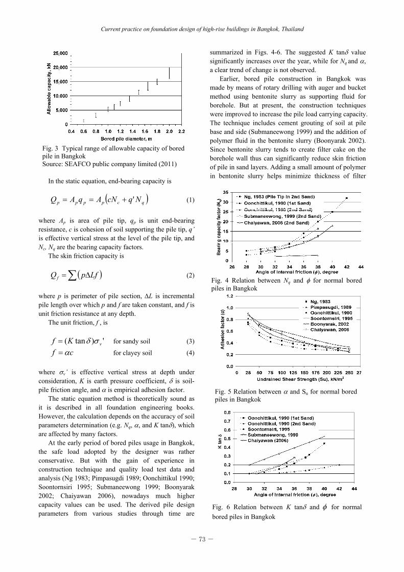
As the scope of this study is on high-rise buildings, the current practice on deep bored piles with tips in the second sand layer is focused. On the basis of past experiences on design and pile load test results of large diameter bored piles, the range of pile capacity can be summarized in Fig. 3.
The survey shows that there were 2 approaches applied for analysis of single pile capacity: 1) the static equation method to determine ultimate load carrying capacity (all interviewees used this method); and also 2) finite element method (FEM) (10% of the interviewees)
Fig. 2 Work flow chart of the design work in SGI group
- 73 -
Current practice on foundation design of high-rise buildings in Bangkok, Thailand
In the static equation, end-bearing capacity is
qcpppp NqcNAqAQ ' (1)
where Ap is area of pile tip, qp is unit end-bearing resistance, c is cohesion of soil supporting the pile tip, q’ is effective vertical stress at the level of the pile tip, and Nc, Nq are the bearing capacity factors.
The skin friction capacity is
LfpQf (2)
where p is perimeter of pile section, L is incremental pile length over which p and f are taken constant, and f is unit friction resistance at any depth.
The unit friction, f , is
')tan( vKf for sandy soil (3)
cf for clayey soil (4)
where v’ is effective vertical stress at depth under consideration, K is earth pressure coefficient, is soil-pile friction angle, and is empirical adhesion factor.
The static equation method is theoretically sound as it is described in all foundation engineering books. However, the calculation depends on the accuracy of soil parameters determination (e.g. Nq, , and K tan), which are affected by many factors.
At the early period of bored piles usage in Bangkok, the safe load adopted by the designer was rather conservative. But with the gain of experience in construction technique and quality load test data and analysis (Ng 1983; Pimpasugdi 1989; Oonchittikul 1990; Soontornsiri 1995; Submaneewong 1999; Boonyarak 2002; Chaiyawan 2006), nowadays much higher capacity values can be used. The derived pile design parameters from various studies through time are
summarized in Figs. 4-6. The suggested K tan value significantly increases over the year, while for Nq and , a clear trend of change is not observed.
Earlier, bored pile construction in Bangkok was made by means of rotary drilling with auger and bucket method using bentonite slurry as supporting fluid for borehole. But at present, the construction techniques were improved to increase the pile load carrying capacity. The technique includes cement grouting of soil at pile base and side (Submaneewong 1999) and the addition of polymer fluid in the bentonite slurry (Boonyarak 2002). Since bentonite slurry tends to create filter cake on the borehole wall thus can significantly reduce skin friction of pile in sand layers. Adding a small amount of polymer in bentonite slurry helps minimize thickness of filter
Fig. 3 Typical range of allowable capacity of bored pile in Bangkok Source: SEAFCO public company limited (2011)
Fig. 4 Relation between Nq and for normal bored piles in Bangkok
Fig. 5 Relation between and Su for normal bored piles in Bangkok
Fig. 6 Relation between K tan and for normal bored piles in Bangkok
- 74 -
Amornfa, et al.
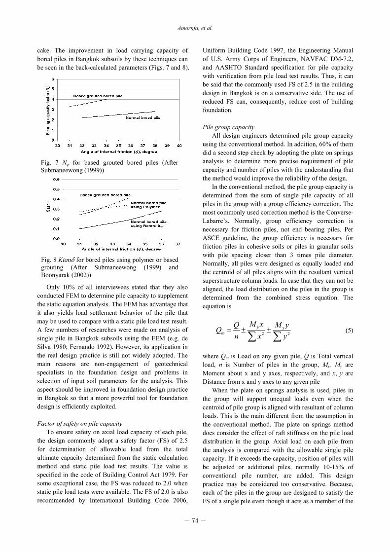
cake. The improvement in load carrying capacity of bored piles in Bangkok subsoils by these techniques can be seen in the back-calculated parameters (Figs. 7 and 8).
Only 10% of all interviewees stated that they also conducted FEM to determine pile capacity to supplement the static equation analysis. The FEM has advantage that it also yields load settlement behavior of the pile that may be used to compare with a static pile load test result. A few numbers of researches were made on analysis of single pile in Bangkok subsoils using the FEM (e.g. de Silva 1980; Fernando 1992). However, its application in the real design practice is still not widely adopted. The main reasons are non-engagement of geotechnical specialists in the foundation design and problems in selection of input soil parameters for the analysis. This aspect should be improved in foundation design practice in Bangkok so that a more powerful tool for foundation design is efficiently exploited.
Factor of safety on pile capacity
To ensure safety on axial load capacity of each pile, the design commonly adopt a safety factor (FS) of 2.5 for determination of allowable load from the total ultimate capacity determined from the static calculation method and static pile load test results. The value is specified in the code of Building Control Act 1979. For some exceptional case, the FS was reduced to 2.0 when static pile load tests were available. The FS of 2.0 is also recommended by International Building Code 2006,
Uniform Building Code 1997, the Engineering Manual of U.S. Army Corps of Engineers, NAVFAC DM-7.2, and AASHTO Standard specification for pile capacity with verification from pile load test results. Thus, it can be said that the commonly used FS of 2.5 in the building design in Bangkok is on a conservative side. The use of reduced FS can, consequently, reduce cost of building foundation.
Pile group capacity
All design engineers determined pile group capacity using the conventional method. In addition, 60% of them did a second step check by adopting the plate on springs analysis to determine more precise requirement of pile capacity and number of piles with the understanding that the method would improve the reliability of the design.
In the conventional method, the pile group capacity is determined from the sum of single pile capacity of all piles in the group with a group efficiency correction. The most commonly used correction method is the Converse-Labarre’s. Normally, group efficiency correction is necessary for friction piles, not end bearing piles. Per ASCE guideline, the group efficiency is necessary for friction piles in cohesive soils or piles in granular soils with pile spacing closer than 3 times pile diameter. Normally, all piles were designed as equally loaded and the centroid of all piles aligns with the resultant vertical superstructure column loads. In case that they can not be aligned, the load distribution on the piles in the group is determined from the combined stress equation. The equation is
22 yyM
xxM
nQQ xy
m (5)
where Qm is Load on any given pile, Q is Total vertical load, n is Number of piles in the group, Mx, My are Moment about x and y axes, respectively, and x, y are Distance from x and y axes to any given pile
When the plate on springs analysis is used, piles in the group will support unequal loads even when the centroid of pile group is aligned with resultant of column loads. This is the main different from the assumption in the conventional method. The plate on springs method does consider the effect of raft stiffness on the pile load distribution in the group. Axial load on each pile from the analysis is compared with the allowable single pile capacity. If it exceeds the capacity, position of piles will be adjusted or additional piles, normally 10-15% of conventional pile number, are added. This design practice may be considered too conservative. Because, each of the piles in the group are designed to satisfy the FS of a single pile even though it acts as a member of the
Fig. 7 Nq for based grouted bored piles (After Submaneewong (1999))
Fig. 8 Ktan for bored piles using polymer or based grouting (After Submaneewong (1999) and Boonyarak (2002))

- 75 -
Current practice on foundation design of high-rise buildings in Bangkok, Thailand
group. This design practice then results in a FS of the pile group much higher than the required FS of single pile acting alone.
In the plate on springs analysis the key input parameter is the spring stiffness representing a pile for which the selection of correct values for the analysis has always been a question. Normally, the value is preferably determined from the load settlement curve from static pile load tests. Few other methods also used in Bangkok practice, when pile load tests are not available, are the empirical estimate of kp = 2EA/L (E = young modulus of pile, A = cross sectional area of pile, and L = pile length) and FEM via PLAXIS software to simulate pile load settlement curve.
Based on an analysis on load settlement curves of 237 static pile load tests of piles in Bangkok subsoils, Kiattivisanchai (2001) summarized that kp values of bored piles are in the range of 0.5EA/L to 4EA/L with the mean value of 2EA/L as shown in Fig. 9.
The weakness of the plate on springs type of analysis for pile group foundation is that it can not directly consider the interaction effect between piles in the group. Owing to the pile interaction effect, edge piles will behave stiffer than the inner piles even though they are of the same size. The method to consider this effect may follow the superposition principle given in a number of literatures, e.g. Poulos and Davis (1980), Randolph (1983), and Kitiyodom and Matsumoto (2002). Alternatively the approximation method is by doubling the exterior edge spring as proposed by Bowles (1986) may also be used. However, for a large pile group this spring stiffness correction method is not simple and reliable to apply.
Structural design of foundation
In accordance with the methods employed for pile group analysis, the bending moment and shear force in the raft for structural design are determined from the
conventional calculation method and plate on pile springs method. In Bangkok practice, 80% of the interviewees stated that they used the latter method. Settlement analysis
From the survey, 70% of total interviewees checked the settlement condition. The remaining 30% did not bother to check because they take it for granted the settlement is small once they specifies depth of tip of bored piles in the second sand layer. As the matter of fact, all interviewees stated that the design should follows the criteria that pile tips shall only be placed in the sand layer, not in the stiff to hard clay layer. For differential settlement control, they adopted the design criteria that all piles used in the building must have the same pile tip depths. In addition, separation/movement joints are provided along the interface between the podium and tower zones of a building to prevent potential damages from differential settlement.
The equivalent raft method suggested by Tomlinson and the one-dimensional consolidation method were popularly used for calculation of building settlement in Bangkok (71.4% of interviewees who do settlement analysis). The remaining adopted 2D FEM analysis such as PLAXIS. In the FEM analysis, undrained analysis was used for prediction of short-term settlement and drained analysis was used for long-term settlement. The plate on pile springs analysis also give settlement of foundation but it was considered as the short term settlement. Some designer used it as a basis to check differential settlement of the foundation. Currently, none of the designers adopted 3D FEM for settlement analysis of the high-rise buildings.
In the current design practice, it is considered that the settlement prediction of high-rise buildings in Bangkok subsoils is not a simple task to perform thus the results of prediction by all methods currently used are questionable. One reason is that there have been on few cases of systematic monitoring of building settlements from the start of the construction to the completion. As an example, record of settlement data of one high-rise building in Bangkok is shown herein. The building had 35 storeys with raft size 81 m x 47 m. Its foundation is a rectangular raft of 2.5-m thickness resting on 1-m diameter bored piles. Pile tip depth is 40 m below ground surface in the second sand layer. The numbers of piles under the tower is 299. The design load per pile was 4100 kN/pile. At the construction time of 15th floor, which 43% of completed floor, the settlements recorded from both towers were about 4-5 mm. These settlements were almost half of predicted immediate settlements of 13.2 mm. Moreover predicted consolidation settlements will reach to 160 mm for this tower.
Fig. 9 The relation between axial stiffness and vertical stiffness of bored piles (After Kiattivisanchai (2001))
- 76 -
Amornfa, et al.
APPLICATION OF PILED RAFT FOUNDATION CONCEPT
In piled raft foundation design concept, some portion
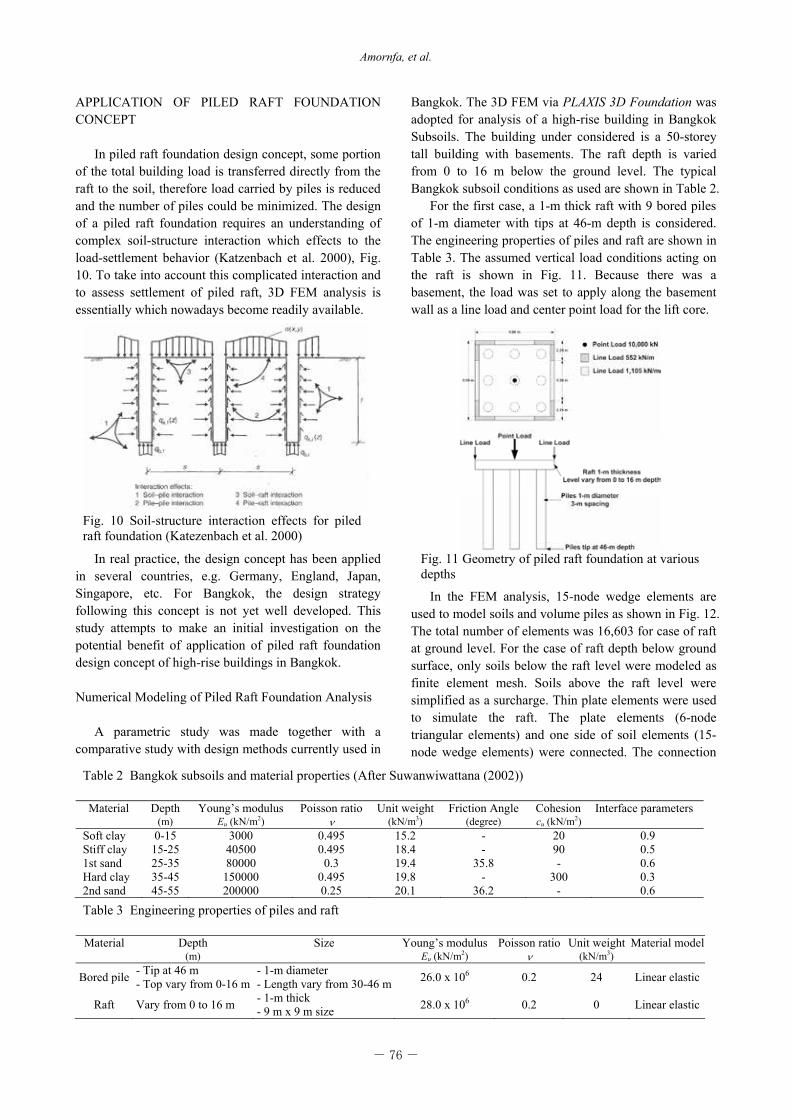
of the total building load is transferred directly from the raft to the soil, therefore load carried by piles is reduced and the number of piles could be minimized. The design of a piled raft foundation requires an understanding of complex soil-structure interaction which effects to the load-settlement behavior (Katzenbach et al. 2000), Fig. 10. To take into account this complicated interaction and to assess settlement of piled raft, 3D FEM analysis is essentially which nowadays become readily available.
In real practice, the design concept has been applied in several countries, e.g. Germany, England, Japan, Singapore, etc. For Bangkok, the design strategy following this concept is not yet well developed. This study attempts to make an initial investigation on the potential benefit of application of piled raft foundation design concept of high-rise buildings in Bangkok.
Numerical Modeling of Piled Raft Foundation Analysis
A parametric study was made together with a
comparative study with design methods currently used in
Bangkok. The 3D FEM via PLAXIS 3D Foundation was adopted for analysis of a high-rise building in Bangkok Subsoils. The building under considered is a 50-storey tall building with basements. The raft depth is varied from 0 to 16 m below the ground level. The typical Bangkok subsoil conditions as used are shown in Table 2.
For the first case, a 1-m thick raft with 9 bored piles of 1-m diameter with tips at 46-m depth is considered. The engineering properties of piles and raft are shown in Table 3. The assumed vertical load conditions acting on the raft is shown in Fig. 11. Because there was a basement, the load was set to apply along the basement wall as a line load and center point load for the lift core.
In the FEM analysis, 15-node wedge elements are used to model soils and volume piles as shown in Fig. 12. The total number of elements was 16,603 for case of raft at ground level. For the case of raft depth below ground surface, only soils below the raft level were modeled as finite element mesh. Soils above the raft level were simplified as a surcharge. Thin plate elements were used to simulate the raft. The plate elements (6-node triangular elements) and one side of soil elements (15-node wedge elements) were connected. The connection
Fig. 10 Soil-structure interaction effects for piled raft foundation (Katezenbach et al. 2000)
Table 3 Engineering properties of piles and raft Material Depth Size Young’s modulus Poisson ratio Unit weight Material model
(m) Eu (kN/m2) (kN/m3)
Bored pile - Tip at 46 m - Top vary from 0-16 m
- 1-m diameter - Length vary from 30-46 m 26.0 x 10⁶ 0.2 24 Linear elastic
Raft Vary from 0 to 16 m - 1-m thick - 9 m x 9 m size 28.0 x 10⁶ 0.2 0 Linear elastic
Table 2 Bangkok subsoils and material properties (After Suwanwiwattana (2002)) Material Depth Young’s modulus Poisson ratio Unit weight Friction Angle Cohesion Interface parameters
(m) Eu (kN/m2) (kN/m3) (degree) cu (kN/m2) Soft clay 0-15 3000 0.495 15.2 - 20 0.9 Stiff clay 15-25 40500 0.495 18.4 - 90 0.5 1st sand 25-35 80000 0.3 19.4 35.8 - 0.6 Hard clay 35-45 150000 0.495 19.8 - 300 0.3 2nd sand 45-55 200000 0.25 20.1 36.2 - 0.6
Fig. 11 Geometry of piled raft foundation at various depths
- 77 -
Current practice on foundation design of high-rise buildings in Bangkok, Thailand
Fig. 12 Finite element mesh with raft and piles in PLAXIS 3D Foundation
Fig. 13 Relation of load shared and raft depth in Bangkok subsoils
Fig. 14 Foundation configuration in this study
was not rigid connection. Interface behavior between plate elements and soil elements are taken care by Rinter. The Mohr-Coulomb model (linear elasto-plastic) was used to model soil properties. The 16-node interface elements were introduced on the surface of the pile. The interface elements had zero thickness and their strengths were scaled down from the strength of surrounding soils by interface parameters which were equivalent to adhesion factors for determination of the skin frictions of soils. Only short term behavior of the piled raft foundation was investigated, thus the total stress undrained strength parameters of clay layers were used in the analysis. Consolidation process during construction was not considered in 3D FEM. Since pile tip in this case of study is resting on sand layer, consolidation during construction may not be so significant as in the case of pile tip resting on clay layer.
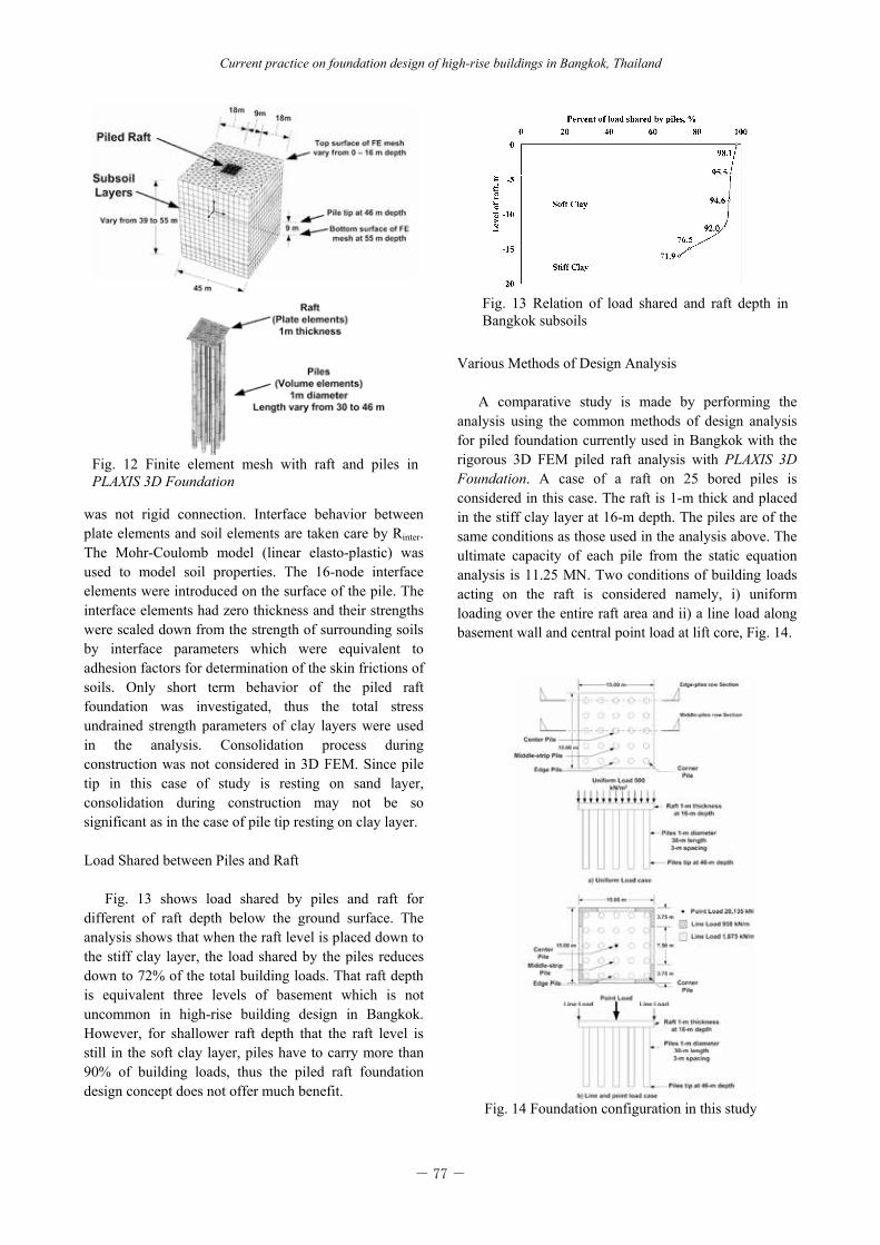
Load Shared between Piles and Raft
Fig. 13 shows load shared by piles and raft for
different of raft depth below the ground surface. The analysis shows that when the raft level is placed down to the stiff clay layer, the load shared by the piles reduces down to 72% of the total building loads. That raft depth is equivalent three levels of basement which is not uncommon in high-rise building design in Bangkok. However, for shallower raft depth that the raft level is still in the soft clay layer, piles have to carry more than 90% of building loads, thus the piled raft foundation design concept does not offer much benefit.
Various Methods of Design Analysis
A comparative study is made by performing the
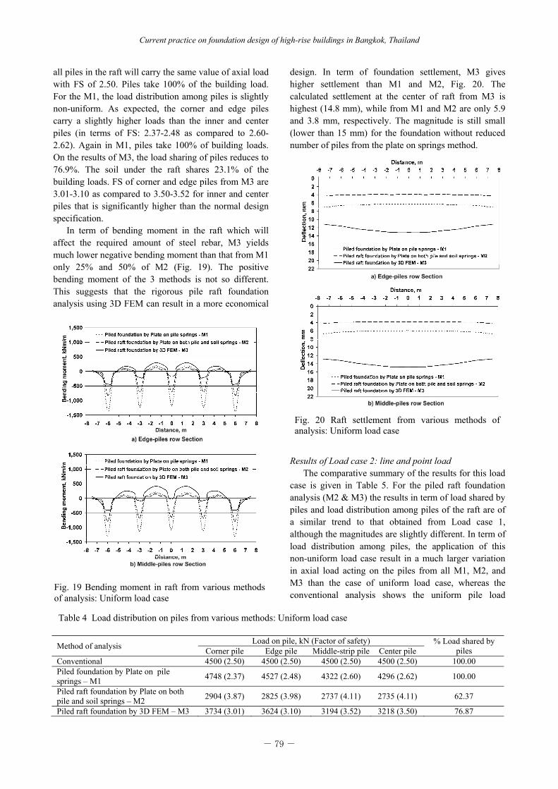
analysis using the common methods of design analysis for piled foundation currently used in Bangkok with the rigorous 3D FEM piled raft analysis with PLAXIS 3D Foundation. A case of a raft on 25 bored piles is considered in this case. The raft is 1-m thick and placed in the stiff clay layer at 16-m depth. The piles are of the same conditions as those used in the analysis above. The ultimate capacity of each pile from the static equation analysis is 11.25 MN. Two conditions of building loads acting on the raft is considered namely, i) uniform loading over the entire raft area and ii) a line load along basement wall and central point load at lift core, Fig. 14.

- 78 -
Amornfa, et al.
Fig. 15 The plate on pile springs method (M1)
The 3 methods of analysis that are carried out are: Method 1 (M1): Piled foundation analysis by the
plate on pile springs method. The analysis is made using SAP2000: The method is most commonly used in current Bangkok design practice. In this method the contribution of soil below the raft, the pile-pile and pile-raft interactions are ignored. The analysis model consists of 900 plate elements and 25 vertical springs as shown in Fig. 15. In order for the results of this method of analysis to be rightly compared with the results of 3D FEM analysis, the pile spring stiffness is obtained from a 3D FEM simulation of a single bored pile of the same size and length installed in the same Bangkok subsoils as used in the piled raft foundation analysis, Fig. 16. The result shows a spring stiffness value of 7.22 x 10⁵ kN/m, which was equal to 1.06EA/L. The value is within the range reported by Kiattivisanchai (2001), but lower than the mean value of 2EA/L. For the plate on pile springs analysis the use of lower value of pile spring stiff across the board will not have effect on the load distribution among piles and bending moment in the raft, it only affect settlements of raft.
Method 2 (M2): Piled raft foundation analysis by the
plate on both pile and soil springs. The analysis is similar to M1 except for that soil springs between piles are included. In the analysis, the soil springs were modeled at 1-m spacing underneath the entire raft. The model consists of 900 plate elements and 25 pile springs and 200 soil springs as shown in Fig. 17. The stiffness of soil spring was obtained from the modulus of subgrade equation proposed by Vesic (1961);
AreaB
Ek ss
)1( 2 (6)
For the undrained modulus of the stiff clay (Es) of
40,500 kN/m2 and Poisson ratio of 0.495, the soil spring stiffness (ks) was calculated as 5.36x10⁴ kN/m. Although this method of analysis considers the contribution of soil resistance below the raft, the pile-pile interactions could not be directly considered.
Method 3 (M3): 3D FEM piled raft foundation
analysis. This rigorous 3D analysis using PLAXIS 3D Foundation program can directly consider the details of subsoil layers within which the piles are installed and the interactions among piles soil and raft. The soil and pile models consist of 18,194 elements, mainly 15-node wedge elements as shown in Fig. 18. Thin plate elements were used to simulate the raft. The subsoil conditions and engineering properties as well as the staged simulation are the same as described in the early section.
Results of Load case 1: uniform load
The comparison on the results for Load Case 1 is shown in Table 4. The result of the conventional method is also included. According to the conventional method,
Fig. 17 The plate on pile and soil springs method (M2)
Fig. 16 Load-settlement curve from simulation of the pile load test by PLAXIS 3D Foundation
Fig. 18 The 3D FEM (M3)
- 79 -
Current practice on foundation design of high-rise buildings in Bangkok, Thailand
Table 4 Load distribution on piles from various methods: Uniform load case
Method of analysis Load on pile, kN (Factor of safety) % Load shared by piles Corner pile Edge pile Middle-strip pile Center pile
Conventional 4500 (2.50) 4500 (2.50) 4500 (2.50) 4500 (2.50) 100.00 Piled foundation by Plate on pile springs – M1 4748 (2.37) 4527 (2.48) 4322 (2.60) 4296 (2.62) 100.00
Piled raft foundation by Plate on both pile and soil springs – M2 2904 (3.87) 2825 (3.98) 2737 (4.11) 2735 (4.11) 62.37
Piled raft foundation by 3D FEM – M3 3734 (3.01) 3624 (3.10) 3194 (3.52) 3218 (3.50) 76.87
all piles in the raft will carry the same value of axial load with FS of 2.50. Piles take 100% of the building load. For the M1, the load distribution among piles is slightly non-uniform. As expected, the corner and edge piles carry a slightly higher loads than the inner and center piles (in terms of FS: 2.37-2.48 as compared to 2.60-2.62). Again in M1, piles take 100% of building loads. On the results of M3, the load sharing of piles reduces to 76.9%. The soil under the raft shares 23.1% of the building loads. FS of corner and edge piles from M3 are 3.01-3.10 as compared to 3.50-3.52 for inner and center piles that is significantly higher than the normal design specification.
In term of bending moment in the raft which will affect the required amount of steel rebar, M3 yields much lower negative bending moment than that from M1 only 25% and 50% of M2 (Fig. 19). The positive bending moment of the 3 methods is not so different. This suggests that the rigorous pile raft foundation analysis using 3D FEM can result in a more economical
design. In term of foundation settlement, M3 gives higher settlement than M1 and M2, Fig. 20. The calculated settlement at the center of raft from M3 is highest (14.8 mm), while from M1 and M2 are only 5.9 and 3.8 mm, respectively. The magnitude is still small (lower than 15 mm) for the foundation without reduced number of piles from the plate on springs method.
Results of Load case 2: line and point load
The comparative summary of the results for this load case is given in Table 5. For the piled raft foundation analysis (M2 & M3) the results in term of load shared by piles and load distribution among piles of the raft are of a similar trend to that obtained from Load case 1, although the magnitudes are slightly different. In term of load distribution among piles, the application of this non-uniform load case result in a much larger variation in axial load acting on the piles from all M1, M2, and M3 than the case of uniform load case, whereas the conventional analysis shows the uniform pile load
Fig. 19 Bending moment in raft from various methods of analysis: Uniform load case
Fig. 20 Raft settlement from various methods of analysis: Uniform load case
- 80 -
Amornfa, et al.
Table 5 Load distribution on piles from various methods: Line and point load case
Method of analysis Load on pile, kN (Factor of safety) % Load shared by piles Corner pile Edge pile Middle-strip pile Center pile
Conventional 4500 (2.50) 4500 (2.50) 4500 (2.50) 4500 (2.50) 100.00 Piled foundation by Plate on pile springs – M1 7471 (1.51) 4865 (2.31) 2351 (4.79) 3913 (2.88) 100.00
Piled raft foundation by Plate on both pile and soil springs – M2 4613 (2.44) 3104 (3.62) 1419 (7.93) 3199 (3.52) 61.14
Piled raft foundation by 3D FEM – M3 5218 (2.16) 3780 (2.98) 1584 (7.10) 4386 (2.56) 71.15
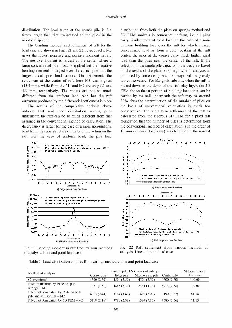
Fig. 21 Bending moment in raft from various methods of analysis: Line and point load case
Fig. 22 Raft settlement from various methods of analysis: Line and point load case
distribution. The load taken at the corner pile is 3-4 times larger than that transmitted to the piles in the middle strip zone.
The bending moment and settlement of raft for the load case are shown in Figs. 21 and 22, respectively. M3 gives the lowest negative and positive moment in raft. The positive moment is largest at the center where a large concentrated point load is applied but the negative bending moment is largest over the corner pile that the largest axial pile load occurs. On settlement, the settlement at the center of raft from M3 was highest (15.4 mm), while from the M1 and M2 are only 5.3 and 4.3 mm, respectively. The values are not so much different from the uniform load case but the raft curvature produced by the differential settlement is more.
The results of the comparative analysis above indicate that real load distribution among piles underneath the raft can be so much different from that assumed in the conventional method of calculation. The discrepancy is larger for the case of a more non-uniform load from the superstructure of the building acting on the raft. For the case of uniform load, the pile load
distribution from both the plate on springs method and 3D FEM analysis is somewhat uniform, i.e. all piles carry similar level of axial load. In the case of a non-uniform building load over the raft for which a large concentrated load as from a core locating at the raft center, the piles at the corner carry much higher axial load than the piles near the center of the raft. If the selection of the single pile capacity in the design is based on the results of the plate on springs type of analysis as practiced by some designers, the design will be grossly too conservative. For Bangkok subsoils, when the raft is placed down to the depth of the stiff clay layer, the 3D FEM shows that a portion of building loads that can be carried by the soil underneath the raft may be around 30%, thus the determination of the number of piles on the basis of conventional calculation is much too conservative. The short term settlement of the raft as calculated from the rigorous 3D FEM for a piled raft foundation that the number of piles is determined from the conventional method of calculation is in the order of 15 mm (uniform load case) which is within the normal
- 81 -
Current practice on foundation design of high-rise buildings in Bangkok, Thailand
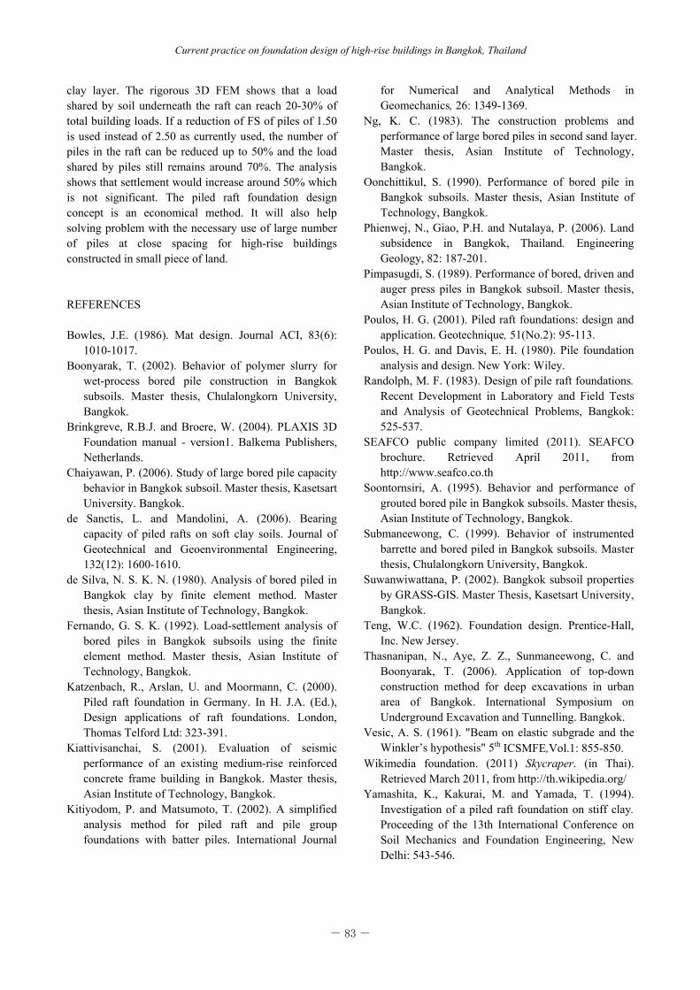
Fig. 24 Comparison on raft settlement between 25-, 21- and 16-pile cases
acceptable level of pile foundation performance used in Bangkok. However, both methods of plate on pile springs and plate on pile and soil springs show much smaller settlement values (4-7 mm) which are not realistic as the methods do not account for the interaction between piles in carrying the vertical loads from the superstructure.
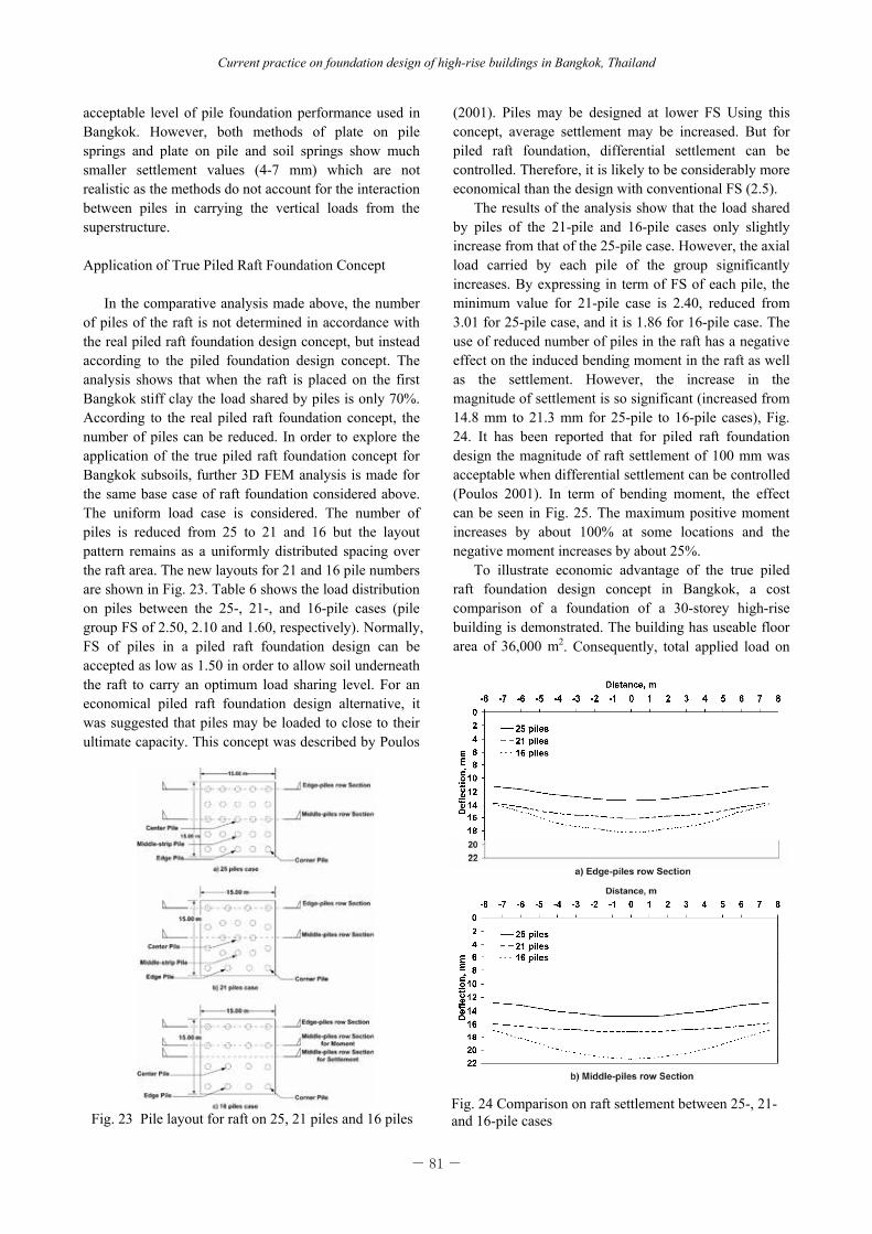
Application of True Piled Raft Foundation Concept
In the comparative analysis made above, the number of piles of the raft is not determined in accordance with the real piled raft foundation design concept, but instead according to the piled foundation design concept. The analysis shows that when the raft is placed on the first Bangkok stiff clay the load shared by piles is only 70%. According to the real piled raft foundation concept, the number of piles can be reduced. In order to explore the application of the true piled raft foundation concept for Bangkok subsoils, further 3D FEM analysis is made for the same base case of raft foundation considered above. The uniform load case is considered. The number of piles is reduced from 25 to 21 and 16 but the layout pattern remains as a uniformly distributed spacing over the raft area. The new layouts for 21 and 16 pile numbers are shown in Fig. 23. Table 6 shows the load distribution on piles between the 25-, 21-, and 16-pile cases (pile group FS of 2.50, 2.10 and 1.60, respectively). Normally, FS of piles in a piled raft foundation design can be accepted as low as 1.50 in order to allow soil underneath the raft to carry an optimum load sharing level. For an economical piled raft foundation design alternative, it was suggested that piles may be loaded to close to their ultimate capacity. This concept was described by Poulos
(2001). Piles may be designed at lower FS Using this concept, average settlement may be increased. But for piled raft foundation, differential settlement can be controlled. Therefore, it is likely to be considerably more economical than the design with conventional FS (2.5).
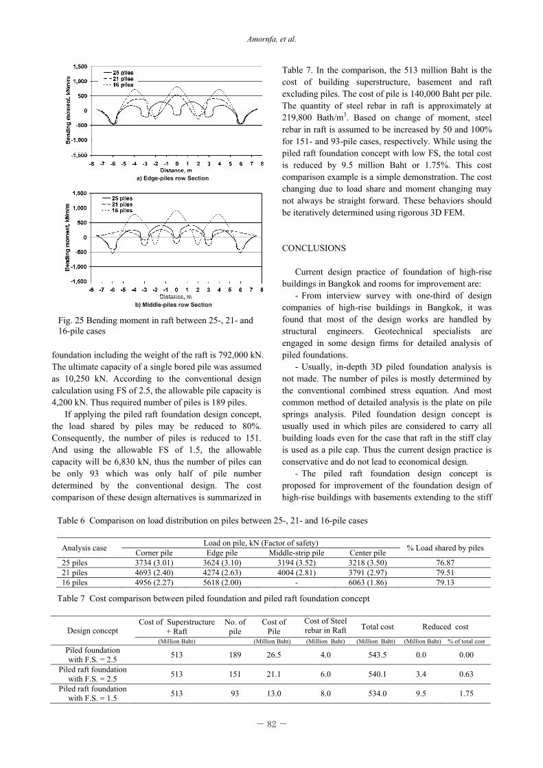
The results of the analysis show that the load shared by piles of the 21-pile and 16-pile cases only slightly increase from that of the 25-pile case. However, the axial load carried by each pile of the group significantly increases. By expressing in term of FS of each pile, the minimum value for 21-pile case is 2.40, reduced from 3.01 for 25-pile case, and it is 1.86 for 16-pile case. The use of reduced number of piles in the raft has a negative effect on the induced bending moment in the raft as well as the settlement. However, the increase in the magnitude of settlement is so significant (increased from 14.8 mm to 21.3 mm for 25-pile to 16-pile cases), Fig. 24. It has been reported that for piled raft foundation design the magnitude of raft settlement of 100 mm was acceptable when differential settlement can be controlled (Poulos 2001). In term of bending moment, the effect can be seen in Fig. 25. The maximum positive moment increases by about 100% at some locations and the negative moment increases by about 25%.
To illustrate economic advantage of the true piled raft foundation design concept in Bangkok, a cost comparison of a foundation of a 30-storey high-rise building is demonstrated. The building has useable floor area of 36,000 m2. Consequently, total applied load on
Fig. 23 Pile layout for raft on 25, 21 piles and 16 piles
- 82 -
Amornfa, et al.
Fig. 25 Bending moment in raft between 25-, 21- and 16-pile cases
Table 6 Comparison on load distribution on piles between 25-, 21- and 16-pile cases
Analysis case Load on pile, kN (Factor of safety) % Load shared by pilesCorner pile Edge pile Middle-strip pile Center pile 25 piles 3734 (3.01) 3624 (3.10) 3194 (3.52) 3218 (3.50) 76.87 21 piles 4693 (2.40) 4274 (2.63) 4004 (2.81) 3791 (2.97) 79.51 16 piles 4956 (2.27) 5618 (2.00) - 6063 (1.86) 79.13
Table 7 Cost comparison between piled foundation and piled raft foundation concept
Design concept Cost of Superstructure
+ Raft No. of
pile Cost of
Pile Cost of Steel rebar in Raft Total cost Reduced cost
(Million Baht) (Million Baht) (Million Baht) (Million Baht) (Million Baht) % of total costPiled foundation with F.S. = 2.5 513 189 26.5 4.0 543.5 0.0 0.00
Piled raft foundation with F.S. = 2.5 513 151 21.1 6.0 540.1 3.4 0.63
Piled raft foundation with F.S. = 1.5 513 93 13.0 8.0 534.0 9.5 1.75
foundation including the weight of the raft is 792,000 kN. The ultimate capacity of a single bored pile was assumed as 10,250 kN. According to the conventional design calculation using FS of 2.5, the allowable pile capacity is 4,200 kN. Thus required number of piles is 189 piles.
If applying the piled raft foundation design concept, the load shared by piles may be reduced to 80%. Consequently, the number of piles is reduced to 151. And using the allowable FS of 1.5, the allowable capacity will be 6,830 kN, thus the number of piles can be only 93 which was only half of pile number determined by the conventional design. The cost comparison of these design alternatives is summarized in
Table 7. In the comparison, the 513 million Baht is the cost of building superstructure, basement and raft excluding piles. The cost of pile is 140,000 Baht per pile. The quantity of steel rebar in raft is approximately at 219,800 Bath/m3. Based on change of moment, steel rebar in raft is assumed to be increased by 50 and 100% for 151- and 93-pile cases, respectively. While using the piled raft foundation concept with low FS, the total cost is reduced by 9.5 million Baht or 1.75%. This cost comparison example is a simple demonstration. The cost changing due to load share and moment changing may not always be straight forward. These behaviors should be iteratively determined using rigorous 3D FEM.
CONCLUSIONS Current design practice of foundation of high-rise
buildings in Bangkok and rooms for improvement are: - From interview survey with one-third of design
companies of high-rise buildings in Bangkok, it was found that most of the design works are handled by structural engineers. Geotechnical specialists are engaged in some design firms for detailed analysis of piled foundations.
- Usually, in-depth 3D piled foundation analysis is not made. The number of piles is mostly determined by the conventional combined stress equation. And most common method of detailed analysis is the plate on pile springs analysis. Piled foundation design concept is usually used in which piles are considered to carry all building loads even for the case that raft in the stiff clay is used as a pile cap. Thus the current design practice is conservative and do not lead to economical design.
- The piled raft foundation design concept is proposed for improvement of the foundation design of high-rise buildings with basements extending to the stiff
- 83 -
Current practice on foundation design of high-rise buildings in Bangkok, Thailand
clay layer. The rigorous 3D FEM shows that a load shared by soil underneath the raft can reach 20-30% of total building loads. If a reduction of FS of piles of 1.50 is used instead of 2.50 as currently used, the number of piles in the raft can be reduced up to 50% and the load shared by piles still remains around 70%. The analysis shows that settlement would increase around 50% which is not significant. The piled raft foundation design concept is an economical method. It will also help solving problem with the necessary use of large number of piles at close spacing for high-rise buildings constructed in small piece of land.
REFERENCES Bowles, J.E. (1986). Mat design. Journal ACI, 83(6):
1010-1017. Boonyarak, T. (2002). Behavior of polymer slurry for
wet-process bored pile construction in Bangkok subsoils. Master thesis, Chulalongkorn University, Bangkok.
Brinkgreve, R.B.J. and Broere, W. (2004). PLAXIS 3D Foundation manual - version1. Balkema Publishers, Netherlands.
Chaiyawan, P. (2006). Study of large bored pile capacity behavior in Bangkok subsoil. Master thesis, Kasetsart University. Bangkok.
de Sanctis, L. and Mandolini, A. (2006). Bearing capacity of piled rafts on soft clay soils. Journal of Geotechnical and Geoenvironmental Engineering, 132(12): 1600-1610.
de Silva, N. S. K. N. (1980). Analysis of bored piled in Bangkok clay by finite element method. Master thesis, Asian Institute of Technology, Bangkok.
Fernando, G. S. K. (1992). Load-settlement analysis of bored piles in Bangkok subsoils using the finite element method. Master thesis, Asian Institute of Technology, Bangkok.
Katzenbach, R., Arslan, U. and Moormann, C. (2000). Piled raft foundation in Germany. In H. J.A. (Ed.), Design applications of raft foundations. London, Thomas Telford Ltd: 323-391.
Kiattivisanchai, S. (2001). Evaluation of seismic performance of an existing medium-rise reinforced concrete frame building in Bangkok. Master thesis, Asian Institute of Technology, Bangkok.
Kitiyodom, P. and Matsumoto, T. (2002). A simplified analysis method for piled raft and pile group foundations with batter piles. International Journal
for Numerical and Analytical Methods in Geomechanics, 26: 1349-1369.
Ng, K. C. (1983). The construction problems and performance of large bored piles in second sand layer. Master thesis, Asian Institute of Technology, Bangkok.
Oonchittikul, S. (1990). Performance of bored pile in Bangkok subsoils. Master thesis, Asian Institute of Technology, Bangkok.
Phienwej, N., Giao, P.H. and Nutalaya, P. (2006). Land subsidence in Bangkok, Thailand. Engineering Geology, 82: 187-201.
Pimpasugdi, S. (1989). Performance of bored, driven and auger press piles in Bangkok subsoil. Master thesis, Asian Institute of Technology, Bangkok.
Poulos, H. G. (2001). Piled raft foundations: design and application. Geotechnique, 51(No.2): 95-113.
Poulos, H. G. and Davis, E. H. (1980). Pile foundation analysis and design. New York: Wiley.
Randolph, M. F. (1983). Design of pile raft foundations. Recent Development in Laboratory and Field Tests and Analysis of Geotechnical Problems, Bangkok: 525-537.
SEAFCO public company limited (2011). SEAFCO brochure. Retrieved April 2011, from http://www.seafco.co.th
Soontornsiri, A. (1995). Behavior and performance of grouted bored pile in Bangkok subsoils. Master thesis, Asian Institute of Technology, Bangkok.
Submaneewong, C. (1999). Behavior of instrumented barrette and bored piled in Bangkok subsoils. Master thesis, Chulalongkorn University, Bangkok.
Suwanwiwattana, P. (2002). Bangkok subsoil properties by GRASS-GIS. Master Thesis, Kasetsart University, Bangkok.
Teng, W.C. (1962). Foundation design. Prentice-Hall, Inc. New Jersey.
Thasnanipan, N., Aye, Z. Z., Sunmaneewong, C. and Boonyarak, T. (2006). Application of top-down construction method for deep excavations in urban area of Bangkok. International Symposium on Underground Excavation and Tunnelling. Bangkok.
Vesic, A. S. (1961). "Beam on elastic subgrade and the Winkler’s hypothesis" 5th ICSMFE,Vol.1: 855-850.
Wikimedia foundation. (2011) Skycraper. (in Thai). Retrieved March 2011, from http://th.wikipedia.org/
Yamashita, K., Kakurai, M. and Yamada, T. (1994). Investigation of a piled raft foundation on stiff clay. Proceeding of the 13th International Conference on Soil Mechanics and Foundation Engineering, New Delhi: 543-546.