current-mode variable frequency quadrature sinusoidal oscillators using two ccs and four passive...
TRANSCRIPT

Current-mode variable frequency quadrature sinusoidaloscillators using two CCs and four passive components includinggrounded capacitors
Abhirup Lahiri
Received: 9 February 2010 / Revised: 8 November 2010 / Accepted: 26 November 2010 / Published online: 9 December 2010
� Springer Science+Business Media, LLC 2010
Abstract This paper reports realizations of current-mode
quadrature sinusoidal oscillator using only two multiple-
output current conveyors (first or second generation current
conveyor CCI/CCII) and four passive components includ-
ing two grounded capacitors. Therefore, the circuits
employ minimum number of passive components to realize
a second-order sinusoidal oscillator. Three types of circuits
are reported depending on the condition of oscillation and
frequency of oscillation (FO). The circuits have FO con-
trollable by either resistor or capacitor and are suitable to
be used as variable frequency oscillator for different
applications. All the circuits provide two explicit quadra-
ture current outputs from high output impedance terminals.
PSPICE simulation results are included to verify the
workability of the proposed circuits.
Keywords Quadrature sinusoidal oscillator � Current-
mode (CM) � Explicit-current-output (ECO) � Current
conveyors (CCs)
1 Introduction
Sinusoidal oscillators are very important analog circuits
and find numerous applications in communication, control
systems; signal processing, instrumentation and measure-
ment systems (see [1] and references cited therein). Since
the advent of current conveyors, namely the first-genera-
tion current conveyor (CCI) and the second-generation
current conveyor (CCII) by Sedra and Smith in [2, 3];
considerable attention has been given to the realizations of
active RC sinusoidal oscillators using current conveyors
(CCs). Several classes of CC-based sinusoidal oscillators
have evolved depending on the number of passive compo-
nents employed and the tuning laws. Single-resistance-
controlled oscillators (SRCOs) using three resistors and two
capacitors have been found to be minimal in realizing
oscillators providing independent tuning of the condition of
oscillation (CO) and the frequency of oscillation (FO) via
two different resistors [4, 5]. Oscillators using four passive
components (including two resistors and two capacitors) are
classified as minimal (or minimum component) oscillators
and are suitable realizing variable frequency oscillators
(VFOs) [6]. 2R-2C VFOs can be mainly classified under two
types depending on the governing tuning laws as follows:
Type1
CO : C1 ¼ C2 ð1Þ
FO : fo ¼1
2p
ffiffiffiffiffiffiffiffiffiffiffiffiffiffiffiffiffiffiffiffi
1
C1C2R1R2
r
ð2Þ
Type2
CO : R1 ¼ R2 ð3Þ
FO : fo ¼1
2p
ffiffiffiffiffiffiffiffiffiffiffiffiffiffiffiffiffiffiffiffi
1
C1C2R1R2
r
ð4Þ
It is clear from (1)–(4) that Type1 oscillators can provide
frequency tuning by means of resistors R1 and R2 and
Type2 oscillators can provide frequency tuning by means
of capacitors C1 and C2. Thus, both type of circuits are
suitable to be used as VFOs. Since realizations of both
voltage-controlled resistors and capacitors are known, both
Type1 and Type2 circuits can be used as voltage-controlled
oscillators (VCOs). 2R-2C VFOs, particularly circuitsA. Lahiri (&)
36-B, J and K Pocket, Dilshad Garden, Delhi, India
e-mail: [email protected]
123
Analog Integr Circ Sig Process (2012) 71:303–311
DOI 10.1007/s10470-010-9571-8

governed by Type1 tuning laws, have been investigated
extensively by several researchers using different CCs.
Some key works include:
(1) CCII based VFO employing two CCIIs and grounded
capacitors proposed by Horng et al. in [7].
(2) CFOA based version of the circuit in [8] by Bhaskar
et al. in [8].
(3) Differential difference current conveyor (DDCC)
based VFO proposed by Kilinc et al. in [6] (circuit
number 6). The circuit, however, used floating
capacitors which is not desirable from monolithic
integration point of view [9].
(4) Differential voltage current conveyor (DVCC) based
VFO by Agarwal in [10] using grounded capacitors and
capable of providing one explicit-current-output (ECO).
(5) Multiple-output DVCC based VFO proposed by
Horng in [11], which uses two DVCCs and grounded
capacitors and is capable of providing two quadrature
ECOs.
(6) Multiple-output fully-differential second-generation
current conveyor (FDCCII) based VFOs by Horng
et al. in [12] which use a single FDCCII and grounded
capacitors while also providing two quadrature ECOs.
This paper discusses realizations of circuits governed
by both Type1 and Type2 tuning laws.
(7) Using adjustable gain second-generation negative
current conveyor in [13], the authors propose a
2R-2C oscillator and its resistor-less equivalent.
Unfortunately, the circuit used floating capacitors and
the suitability of quadrature outputs is not investigated.
Considering the current interest in the design of current-
mode (CM) circuits, oscillators providing explicit-current-
outputs (ECOs) are highly desirable. Such oscillators can
be used as input sources for CM circuits, e.g. CM filters.
The possibility of quadrature functionality in CM oscilla-
tors is another desirable feature which would make the
oscillators suitable for providing two 90� phase shifted
current outputs signals and which could be fed as inputs to
CM quadrature mixers or single sideband modulators [1,
9]. Although many previously reported 2R-2C VFOs have
capability of quadrature signal generation, but to the best of
the author’s knowledge, only two 2R-2C quadrature
oscillators providing two ECOs have been reported in the
literature: (i) by employing multiple-output DVCCs in [11]
and (ii) by employing multiple-output FDCCII in [12]. An
interesting question arises on whether the CM QOs similar
to that in [11, 12] can be created using CCI/CCII? It can be
argued that CCI and CCII are simpler building blocks as
compared to FDCCII or DVCC. Moreover, several types of
CCI and CCII are also available as the off-the-shelf ICs
(e.g. CCII? is available as CFOA AD844 IC by Analog
Devices [14]) and their dual/multiple-output variants can
also be easily created using commercially available ICs.
But complex building blocks like DVCC are not com-
mercially available yet and their construction using com-
mercially available ICs like AD844 requires several ICs
and matched resistors (e.g. DVCC would require three
AD844 ICs and two matched resistors [15]). Thus, the
motivation of this work is to provide similar oscillators as
in [11, 12] (with same tuning laws), but by using simpler
building blocks, namely the CCI and CCII. Multiple-output
CCs are used which help in current copying and generation
of quadrature ECOs. Both Type1 and Type2 oscillator
circuits are reported and another type of CM QO is also
described with its governed tuning laws other than Type1
or Type2. It is worth mentioning here that very recently a
catalogue of oscillators has been reported using SVA [16]
and resistor-less variants of Type2 oscillators have also
been described (Fig. 3e). The circuits reported here have
been verified using PSPICE simulations and the results are
in correspondence with the theory.
2 Proposed circuit
Type1 circuits are shown in Fig. 1 and are derived using
the SVA as briefed in the Appendix A. The circuit in
Fig. 1a is corresponding to the matrix A2, same as the
circuit in [7, 8], but with quadrature signal functionality.
Using routine circuit analysis, one can derive the following
characteristic equation (CE) for the oscillator circuit
s2C1C2R1R2 þ sR1ðC1 � C2Þ þ 1 ¼ 0 ð5ÞSince R1 is grounded, it can be easily replaced by a
non-linearity cancelled MOSFET working in triode region
Fig. 1 Type1 CM QOs
304 Analog Integr Circ Sig Process (2012) 71:303–311
123
[17, 18] (and thereby simulating a voltage controlled
resistor) to create a voltage controlled oscillator (VCO)
[18]. The marked ECOs in Fig. 1a are related as
Io1 ¼ jk1Io2 where k1 ¼1
xoC2R1
¼ffiffiffiffiffiffiffiffiffiffi
C1R2
C2R1
r
ð6Þ
It is clear from (6) that the ECOs are 90� phase shifted and
have equal amplitudes when k1 = 1. Intuitively, the
quadrature nature of the ECOs can be expected since these
are copies of currents flowing in the capacitor C2 and resistor
R1, respectively. An interesting point can be noted from (6)
that both R1 and R2 should be equal and need to be varied
simultaneously (to vary the frequency) so that the ratio of the
generated quadrature signals k1 remains unity. This would
result in balanced amplitude quadrature output generation
and which can be very desirable in some applications. As an
alternative realization, the circuit in Fig. 1a can also be
created using other CCs. One such example, is shown in
Fig. 1b wherein the DO-CCII- has been replaced by a DO-
ICCII? [19]. Note that ICCII, just like DVCC is not available
commercially, nevertheless the circuit is included as an
alternate realization. The resulting oscillator is governed by
the same CE, CO and FO as in (5), (1) and (2), respectively.
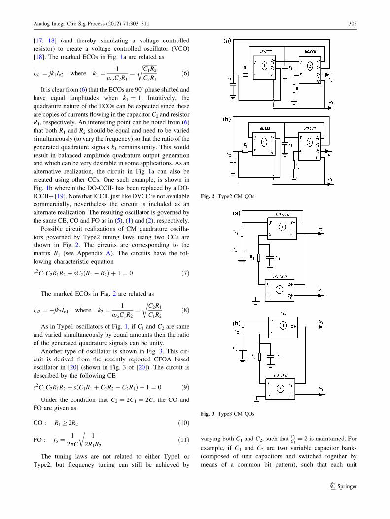
Possible circuit realizations of CM quadrature oscilla-
tors governed by Type2 tuning laws using two CCs are
shown in Fig. 2. The circuits are corresponding to the
matrix B1 (see Appendix A). The circuits have the fol-
lowing characteristic equation
s2C1C2R1R2 þ sC2ðR1 � R2Þ þ 1 ¼ 0 ð7Þ
The marked ECOs in Fig. 2 are related as
Io2 ¼ �jk2Io1 where k2 ¼1
xoC1R2
¼ffiffiffiffiffiffiffiffiffiffi
C2R1
C1R2
r
ð8Þ
As in Type1 oscillators of Fig. 1, if C1 and C2 are same
and varied simultaneously by equal amounts then the ratio
of the generated quadrature signals can be unity.
Another type of oscillator is shown in Fig. 3. This cir-
cuit is derived from the recently reported CFOA based
oscillator in [20] (shown in Fig. 3 of [20]). The circuit is
described by the following CE
s2C1C2R1R2 þ sðC1R1 þ C2R2 � C2R1Þ þ 1 ¼ 0 ð9Þ
Under the condition that C2 ¼ 2C1 ¼ 2C, the CO and
FO are given as
CO : R1� 2R2 ð10Þ
FO : fo ¼1
2pC
ffiffiffiffiffiffiffiffiffiffiffiffiffi
1
2R1R2
r
ð11Þ
The tuning laws are not related to either Type1 or
Type2, but frequency tuning can still be achieved by
varying both C1 and C2, such that C2
C1¼ 2 is maintained. For
example, if C1 and C2 are two variable capacitor banks
(composed of unit capacitors and switched together by
means of a common bit pattern), such that each unit
Fig. 2 Type2 CM QOs
Fig. 3 Type3 CM QOs
Analog Integr Circ Sig Process (2012) 71:303–311 305
123

capacitor of C2 bank is twice the value of the unit capacitor
of C1 bank. The marked ECOs in Fig. 3 are related as
Io1 ¼ jk3Io2 where k3 ¼1
xoC1R1
ð12Þ
3 Non-ideal analysis and discussion
The following non-idealities of the CCs are considered to
analyze their effects on the circuit
(1) The CCs suffer from current and voltage tracking
errors and which deviate the current and voltage
conveyance coefficients from their ideal magnitude of
unity. We use symbols, bij to represent the magnitude
of current conveyance coefficient from x to zj and ai
to represent the voltage conveyance coefficient from
y to x terminal for the ith CC (where i = 1,2,
j ¼ 1; 2; 3; . . .). ci represent the current conveyance
coefficient from y to x terminal for the ith CCI.
(2) The non-zero parasitic resistance Rx appears at the
x terminal of both the CCs and which adds into the
external resistors R1 and R2.
(3) The parasitic capacitance Czijappears between the
high-output impedance zj terminals of the ith CC
and ground and the parasitic capacitance Cyi
appears between the high-input impedance y termi-
nal of the ith CC and ground where (i = 1,2).
Similarly, the parasitic resistance Rzijand Ryi
appear
at zj and y terminals of the ith CC. To alleviate the
effects of the parasitic resistance Rz and Ry at
terminals z and y for circuit in Fig. 1a, the
operating frequency should be chosen such that
fo [ max 12pðC1þCz11
þCy2ÞðRz11
jjRy2Þ;
12pðC2þCy1
ÞRy1
� �
. For
circuit in Fig. 2b, the effects of the parasitic
resistance Rz and Ry can be alleviated by choos-
ing the operating frequency as fo [
max 12pðC1þCz21
þCy1þCy2
ÞðRy1jjRy1jjRz21
Þ;1
2pðC2þCz11þCz22
ÞðRz11jjRz22
Þ
�
Þ.
The aforementioned non-idealities affect both the CO
and FO of the oscillators. For operating frequencies greater
the the lower threshold (as provided above) the effects of
large valued parasitic resistances (Rz or Ry) can be
neglected. Considering other non-idealities, the non-ideal
expressions for the CO and the FO of oscillators are pro-
vided in Table 1.
The results for the CO in Table 1 are very helpful in
realizing practical oscillators. Since the parasitics are not
well controlled and would change with the design of CCs;
considering strict equality of capacitors or resistors for the
CO (e.g. as in (1), (3)), the oscillator may not start-up due
to insufficient open-loop gain. Therefore, sufficient oscil-
lator start-up margins should be taken for design. Other
points to be noted are as follows:
(1) The FO for Type1 circuit in Fig. 1a can still be
independently controlled and tuned via resistors R1
and R2. The external capacitors and resistors can be
kept much larger than the parasitics to minimize the
deviation from the theoretically expected FO.
(2) The non-ideal expressions for Type2 circuits in
Fig. 2, do not exhibit any independence as external
resistor and capacitor terms are present in both CO
and FO. Strictly speaking, only when b11 = 1, the FO
can be tuned independently via capacitors C1 or C2.
However, if b11 is made very close to unity (e.g. by
creating improved current mirrors by cascading), then
the right hand term of the CO can be neglected and
the start-up margin would not be affected much even
if C1 and/or C2 are varied to change the FO.
(3) The non-ideal expressions for Type3 circuits in Fig. 3
have been derived by considering that the operating
frequency fo � C2þCy
2pR2ðC2CyÞ. Under these conditions, Cy
can be neglected and the CE still remains second-
order (if Cy is considered, the CE becomes third-
order). As before, with C2 ¼ 2C1 ¼ 2C, the FO can
be tuned by varying both C1 and C2, such that C2
C1¼ 2
is maintained.
(4) The fo sensitivities for all the external passive
components are no more than 0.5 except for Type3
oscillator with capacitor matching constraint and
where SfoC ¼ �1.
Table 1 Non-ideal CO and FO for oscillators
Circuit CO fo
Type1 Fig. 1a a2c2ðC2 þ Cy1Þ�C1 þ Cz11
þ Cy2 12p
ffiffiffiffiffiffiffiffiffiffiffiffiffiffiffiffiffiffiffiffiffiffiffiffiffiffiffiffiffiffiffiffiffiffiffiffiffiffiffiffiffiffiffiffiffiffiffiffiffiffiffiffiffiffiffiffiffiffiffiffiffiffiffiffi
a1a2b11
ðC1þCz11þCy2
ÞðC2þCy1ÞðR1þRx1
ÞðR2þRx2Þ
q
Type2 Fig. 2b a1ðR2 þ Rx2Þ � a2b21ðR1 þ Rx1
Þ� 12p
ffiffiffiffiffiffiffiffiffiffiffiffiffiffiffiffiffiffiffiffiffiffiffiffiffiffiffiffiffiffiffiffiffiffiffiffiffiffiffiffiffiffiffiffiffiffiffiffiffiffiffiffiffiffiffiffiffiffiffiffiffiffiffiffiffiffiffiffiffiffiffiffiffiffiffiffiffiffiffiffiffiffi
a2b22þa2b21c1ð1�b11ÞðC1þCz21
þCy1þCy2
ÞðC2þCz11þCz22
ÞðR1þRx1ÞðR2þRx2
Þ
q
ðC1þCz21þCy1
þCy2ÞðR2þRx2
Þc1ð1�b11ÞC2þCz11
þCz22
Type3 Fig. 3b R1ð2� a1Þ� 2R2 � 2Rx1þ ða1 � 2ÞRx2
12pC
ffiffiffiffiffiffiffiffiffiffiffiffiffiffiffiffiffiffiffiffiffiffiffiffiffiffiffiffiffi
12ðR1þRx2
ÞðR2�Rx2Þ
q
306 Analog Integr Circ Sig Process (2012) 71:303–311
123

In Table 2, the main features of the reported types of
oscillator circuits here are compared with those of previous
works (restricted to only those dealing with active RC
oscillators).
4 Simulation results
The proposed oscillator circuits have been simulated in
PSPICE using MOSFET implementation of CCI and
DO-CCII-, as shown in Figs. 4 and 5, respectively. Circuit
in Fig. 1a is taken as the design example. The circuit is
implemented with 0.35 lm TSMC CMOS technology [27].
The aspect ratios of the transistors in CCI (of Fig. 4b) and
DO-CCII- are indicated in Tables 3 and 4, respectively and
IB = 50 lA. For Type1 oscillators, the circuit in Fig. 1a is
taken as the design example. It is designed with passive
component values of R1 ¼ R2 ¼ 10 kX, C1 = 100 pF and
C2 = 101 pF. The start-up of oscillations and the steady-
state waveforms for both the ECOs is shown in Fig. 6. The
observed frequency of 149 kHz is in close correspondence
with the theoretical value of 159.1 kHz. The total harmonic
distortion (THD) at both the outputs is less than 0.6%. The
variation of the FO by resistor R1 (and R2 fixed at 10 kX) is
shown in Fig. 7a, the corresponding variation of the output
signal amplitudes is shown in Fig. 7b and the variation of
the THD of current Io1 is shown in Fig. 7c. For Type2
oscillators, the circuit in Fig. 2a is taken as the design
example. It is designed with passive component values of
C1 ¼ C2 ¼ 100 pF, R1 ¼ 10 kX and R2 ¼ 10:1 kX. The
start-up of oscillations and the steady-state waveforms for
both the ECOs is shown in Fig. 8. The observed frequency
is 149.25 kHz and the THD at both the outputs is less than
1.7%. The FO is varied by means of a variable capacitor
bank which consists of 7 unit capacitors each of 5 pF and a
fixed capacitor of Cfix = 65 pF, as shown in Fig. 9. Three
binary bits can be used as control signals and which need to
be converted to thermometric code (n) to switch the seven
capacitors. Simple NMOS transistors with minimum length
and sufficient width to create low resistance switches can
be used. Binary code 000 (equivalent to n = 0) corre-
sponds to all the seven capacitors being OFF and pattern
Table 2 Comparison of features of recently reported ECO oscillators
Circuits Active element
and number
Number.
of passive
elements
ECO Quadrature
ECOs
Independent
FO control
Matching
condition
Figures 1 and 2 in [20] CFOA (2) 5 Yes No Yes Yes
[21] CCI/CCII (2) 5 Yes No Yes Yes
[22] CFOA (1) 6 Yes No No Yes
[23] CFOA (2) 5 Yes No Yes No
[24] DVCC (1) 5 Yes No Yes No
[25] CCII (2) 6 Yes No Yes Yes
[26] CCII-TA (1) 4 Yes Yes Yes No
[9] CDTA (2) 3 Yes Yes Yes No
Proposed CCI/CCII (2) 4 Yes Yes Yes No, yes
for Type3
Fig. 4 Possible MOS implementations of CCI
Analog Integr Circ Sig Process (2012) 71:303–311 307
123

111 (equivalent to n = 7) corresponds to all the seven
capacitors being ON. General expression for the effective
capacitance is given as
C1eff: ¼ Cfix þ nCon þ ð7� nÞCoff ð13Þ
where Con represents the capacitance of the arm which
is switched ON, Con * 5 pF, Coff represents the
capacitance of the arm which is switched OFF (in our
case this capacitance is negligibly small as compared to
the ON capacitance) and n e [0, 1, 2,…, 7] is the ther-
mometric code representing the number of unit capaci-
tors that are ON. The variation of FO with thermometric
code n is shown in Fig. 10a, the corresponding variation
of the output signal amplitudes is shown in Fig. 10b and
the variation of the THD of current Io2 is shown in
Fig. 10c.
5 Concluding remarks
Realizations of variable frequency quadrature sinusoidal
oscillator using two CCs and minimum number of passive
components, namely two resistors and two grounded
capacitors have been demonstrated. As proposed to earlier
such realizations using complex ABBs like multiple-output
FDCCII and DVCC, the proposed circuits here are created
using multiple-output CCI or CCII. Circuit realizations
governed by the most significant CO and FO tuning laws
are provided and are are classified under three types.
Although additional types of tuning laws and correspond-
ing circuit realizations for 2R-2C oscillators are not ruled
out, it is believed that that proposed circuits here along
with those in [11, 12] cover the most significant types of
second-order active RC CM-QOs realizable using only four
passive components.
Appendix A: oscillator synthesis via state variable
method
The method of synthesis of second-order sinusoidal oscil-
lators has been dealt extensively in [5, 16] and here we
restate the important steps. In general, a second-order
oscillator can be characterized by means of the following
matrix equation
dV1
dtdV2
dt
� �
¼ a11 a12
a21 a22
� �
V1
V2
� �
ð14Þ
where V1 and V2 are the state variables and are the voltages
across the two capacitors C1 and C2, respectively. From
(14), the characteristic equation (CE) of the oscillator is
given asFig. 6 Oscillation waveforms of the ECOs for Type1 oscillator in
Fig. 1a: a start-up and b steady-state
Fig. 5 Possible MOS implementation of DO-CCII(-)
Table 3 Transistors widths for CCI
MOSFET W/L (lm/lm)
M3–M4, M8–M9, M13–M15 30/0.5
M1–M2, M5–M7, M10–M12 10/0.5
Table 4 Transistors widths for DO-CCII-
MOSFET W/L (lm/lm)
M3–M4, M8–M9, M12–M13, M16–M18 30/0.5
M1–M2, M5–M7, M10–M11, M14–M15, M19 10/0.5
308 Analog Integr Circ Sig Process (2012) 71:303–311
123

s2 � sða11 þ a22Þ þ ða11a22 � a12a21Þ ¼ 0 ð15Þ
It is evident from (15) that
CO : a11 ¼ �a22 ð16Þ
FO : fo ¼1
2p
ffiffiffiffiffiffiffiffiffiffiffiffiffiffiffiffiffiffiffiffiffiffiffiffiffiffiffiffiffiffi
a11a22 � a12a21
p ð17Þ
Comparing (16) and (17) with the desired tuning laws as in
(1) and (2) for Type1 oscillators and (3) and (4) for Type2,
8 9 10 11 12 13 14 15100
120
140
160
180
200
Resistor R1 (kOhms)
Fre
quen
cy (
kHz)
115 120 125 130 135 140 145 150 155 160 165 17060
80
100
120
140
Operating Frequency
Cur
rent
am
plitu
des
(uA
)
115 120 125 130 135 140 145 150 155 160 165 1700
0.5
1
1.5
Operating Frequency
TH
D o
f cur
rent
Io1
(%)
Theoretical
Simulated
Io2
Io1
(a)
(b)
(c)
Fig. 7 a FO variation with
resistor R1, b amplitude
variation with frequency, c THD
variation with frequency
Fig. 8 Oscillation waveforms of the ECOs for Type2 oscillator in
Fig. 2a: a start-up and b steady-state Fig. 9 Variable capacitor bank for FO tuning
Analog Integr Circ Sig Process (2012) 71:303–311 309
123

we can derive different matrices by appropriately choosing
the parameters aij (where i = 1,2). For Type1 oscillators
the following matrices are possible
A1 ¼1
C1R1
1C1R1
� 1C2ð 1
R1þ 1
R2Þ � 1
C2R1
" #
;
A2 ¼1
C1R1� 1
C1R1
1C2ð 1
R1þ 1
R2Þ � 1
C2R1
" # ð18Þ
A3 ¼� 1
C1R1
1C1R1
� 1C2ð 1
R1þ 1
R2Þ 1
C2R1
;
" #
A4 ¼� 1
C1R1� 1
C1R1
1C2ð 1
R1þ 1
R2Þ 1
C2R1
" # ð19Þ
A total of four different oscillator circuits can be
realized corresponding to each Ak matrix (k = 1, 2, 3, 4),
but it is sufficient to give CC based realization of any one
of the matrix in the class and the rest can be derived by
simple interchange of sign of the output current, i.e. by
utilizing either z ? or z- terminal of multiple current
output CC. For Type2 oscillators the following matrices are
possible
B1 ¼1
C1ð 1
R1� 1
R2Þ � 1
C1R11
C2R20
" #
; B2 ¼1
C1ð 1
R1� 1
R2Þ 1
C1R1
� 1C2R2
0
" #
ð20Þ
B3¼� 1
C1ð 1
R1� 1
R2Þ 1
C1R1
� 1C2R2
0
" #
; B4¼� 1
C1ð 1
R1� 1
R2Þ 1
C1R1
� 1C2R2
0
" #
ð21Þ
References
1. Tangsrirat, W., Prasertsom, D., Piyatat, T., & Surakompontorn,
W. (2008). Single-resistance-controlled quadrature oscillators
using current differencing buffered amplifiers. InternationalJournal of Electronics, 95(11), 1119–1126.
2. Smith, K. C., & Sedra, A. (1968). The current conveyor: A new
circuit building block. IEEE Proceedings, 56, 1368–1369.
3. Sedra, A., & Smith, K. C. (1970). A second-generation current
conveyor and its application. IEEE Transactions on CircuitTheory, 17, 133–134.
4. Soliman, A. M. (2009). Generation of current conveyor based
oscillators using nodal admittance matrix expansion. AnalogIntegrated Circuits and Signal Processing (20 Dec 2009).
doi:10.1007/s10470-009-9432-5.
0 1 2 3 4 5 6 7140
160
180
200
Thermometric Code (n)
Fre
quen
cy (
kHz)
145 150 155 160 165 170 175 180 185110
120
130
140
150
Operating Frequency
Cur
rent
am
plitu
des
(uA
)
145 150 155 160 165 170 175 180 1851
1.2
1.4
1.6
1.8
Operating Frequency
TH
D o
f cur
rent
Io2
(%)
Theoretical
Simulated
Io2
Io1
(a)
(b)
(c)
Fig. 10 a FO variation with
thermometric code, b amplitude
variation with frequency, c THD
variation with frequency
310 Analog Integr Circ Sig Process (2012) 71:303–311
123

5. Senani, R., & Gupta, S. S. (1997). Synthesis of single-resistance-
controlled oscillators using CFOAs: Simple state-variable
approach. IEEE Proceedings Circuits Devices and Systems, 144,
104–106.
6. Kilinc, S., Jain, V., Aggarwal, V., & Cam, U. (2006). Catalogue
of variable frequency and single-resistance-controlled oscillators
employing a single differential difference complementary current
conveyor. Frequenz, 60(7–8), 142–146.
7. Horng, J. W. (2001). A sinusoidal oscillator using current-con-
trolled current conveyors. International Journal of Electronics,88(6), 659–664.
8. Bhaskar, D. R., & Senani, R. (2006). New CFOA-based single-
element-controlled sinusoidal oscillators. IEEE Transactions onInstrumentation and Measurement, 55(6), 2014–2021.
9. Lahiri, A. (2009). Novel voltage/current-mode quadrature oscil-
lator using current differencing transconductance amplifier.
Analog Integrated Circuits and Signal Processing, 61, 199–203.
10. Agarwal, V., Kilinc, S., & Cam, U. (2006). Minimum component
SRCO and VFO using a single DVCCC.Analog Integrated Cir-cuits and Signal Processing, 49, 181–185.
11. Horng, J. W. (2003). Current-mode quadrature oscillator with
grounded capacitors and resistors using two DVCCs. IEICETransactions on Fundamentals, E86-A(8), 2152–2154.
12. Horng, J. W., et al. (2008). Current or/and voltage-mode quad-
rature oscillators with grounded capacitors and resistors using
FDCCIIs. WSEAS Transactions on Circuits and Systems, 7(3),
129–138.
13. Sotner, R., Hrubos, Z., Slezak, J., & Dostal, T. (2010). Simply
adjustable sinusoidal oscillator based on negative three-port
current conveyors. Radioengineering, 19(3), 446–453.
14. Analog Devices, Linear products data book. Norwood, MA
(1990).
15. Maheshwari, S. (2009). Analogue signal processing applications
using a new circuit topology. IET Proceedings on CircuitsDevices and Systems, 3(3), 106–115.
16. Petrzela, J., Vyskocil, P., & Prokopec, J. (2010). Fundamental
oscillators based on diamond transistors. In Proceedings of 20thinternational conference radioelektronika conference, April
2010, pp. 1–4. doi:10.1109/RADIOELEK.2010.5478555.
17. Maundy, B., Gift, S., & Aronhime, P. (2008). Practical voltage/
current-controlled grounded resistor with dynamic range exten-
sion. IET Proceedings on Circuits Devices and Systems, 2(2),
201–206.
18. Gupta, S. S., Bhaskar, D. R., & Senani, R. (2009). New voltage
controlled oscillators using CFOAs. AEU International Journalof Electronics and Communications, 63, 209–217.
19. Awad, I. A., & Soliman, A. M. (1999). Inverting second gen-
eration current conveyors: The missing building blocks, CMOS
realizations and applications. International Journal of ElectronicHealthcare, 86(4), 413–432.
20. Lahiri, A., Jaikla, W., & Siripruchyanun, M. (2010) Explicit-cur-
rent-output second-order sinusoidal oscillators using two CFOAs
and grounded capacitors. AEU International Journal of Electronicsand Communications. doi:10.1016/j.aeue.2010.09.003.
21. Bhaskar, D. R., Abdalla, K. K., & Senani, R. (2010). New SRCO
with explicit current-mode output using two CCs and grounded
capacitors. In Proceedings of international conference on elec-trical and electronics engineering (ELECO) 2009, November
2009, pp. II-42–II-44.
22. Senani, R., & Sharma, R. K. (2005). Explicit-current-output
sinusoidal oscillators employing only a single current-feedback
op-amp. IEICE Electronics Express, 2(1) 14–18.
23. Gupta, S. S., Sharma, R. K., Bhaskar, D. R., & Senani, R. (2008).
Sinusoidal oscillators with explicit current output employing
current-feedback op-amps. International Journal of Circuit The-ory and Applications. doi:10.1002/cta.531.
24. Gupta, S. S., & Senani, R. (2000). Grounded-capacitor current-
mode SRCO: Novel application of DVCCC. Electronics Letters,36(3), 195–196.
25. Bajer, J., Lahiri, A., & Biolek, D. (2010). Current-mode CCII+
based oscillator circuits using a conventional and modified Wien-
bridge with all capacitors grounded. In Proceedings of IMAPSelectronics, devices and systems international conference, Sept.
1–2, 2010, Brno, Czech Republic, pp. 5–10. ISBN 978-80-214-
4138-5.
26. Lahiri, A. (2009). Explicit-current-output quadrature oscillator
using second-generation current conveyor transconductance
amplifier. Radioengineering, 18(4), 522–526.
27. Yuce, E. (2007). On the implementation of the floating simulators
employing a single active device. AEU International Journal ofElectronics and Communications, 61, 453–458.
Abhirup Lahiri received Bach-
elor of Engineering (B.E.) degree
from the Division of Electronics
and Communications, Netaji
Subhas Institute of Technology
(erstwhile, Delhi Institute of
Technology), University of
Delhi, India. His research inter-
ests include design of compact
analog circuit solutions using
novel voltage-mode and current-
mode active elements. He has
authored/co-authored several
international journal/conference
papers and has acted as a reviewer
(by editor’s invitation) for international journals and conferences. He is a
member of ACEEE, IAENG and IACSIT.
Analog Integr Circ Sig Process (2012) 71:303–311 311
123