current and voltage transducers - europower · pdf filewith more than 2 500 current and...
TRANSCRIPT

Current andVoltage Transducersfor Industrial Applications
2
Dear Customer,
This catalogue summarises the most common productoffering of LEM Components. It is our business tosupport you with both standard and customisedproducts to optimise your application.
Please contact LEM in your region to get assistance.
LEM Components leverages its more than 30 yearsexperience in the application, design and production ofcurrent and voltage transducers, and has established itselfas a market leader with worldwide presence to serve you.An extensive R&D program will ensure that our productoffering will continuously expand over time.
LEM products are utilized across a broad spectrum ofpower electronics applications: industrial motor drives,robots and cranes, cable cars and ski lifts, elevatorsand escalators, ventilation and air conditioning equip-ment, precision medical systems, and power suppliesfor computer servers and mobile telecom.
All these applications require accurate and optimal controlof the electrical energy to insure a high level of efficiency,safety, reliability.
With more than 2 500 current and voltage transducers in itsportfolio, LEM Components offers a complete range ofaccurate, reliable and galvanically isolated devices for themeasurement of currents from 0.25A to 10 000A andvoltages from 10V to 6 400V, in various technologies,open loop and closed loop, and the new Eta technology.
LEM transducers are designed according to the mostdemanding international standards, and carry CE marking.UL or UR listing is also available on selected models.We have worldwide ISO 9000 and ISO TS 16949:2002(Geneva production and design center) qualification, andoffer a 5 year warranty on all our products.
LEM constantly innovates and strives to improve theperformance, cost and dimensions of its products.Several ASIC technology based products are offered.
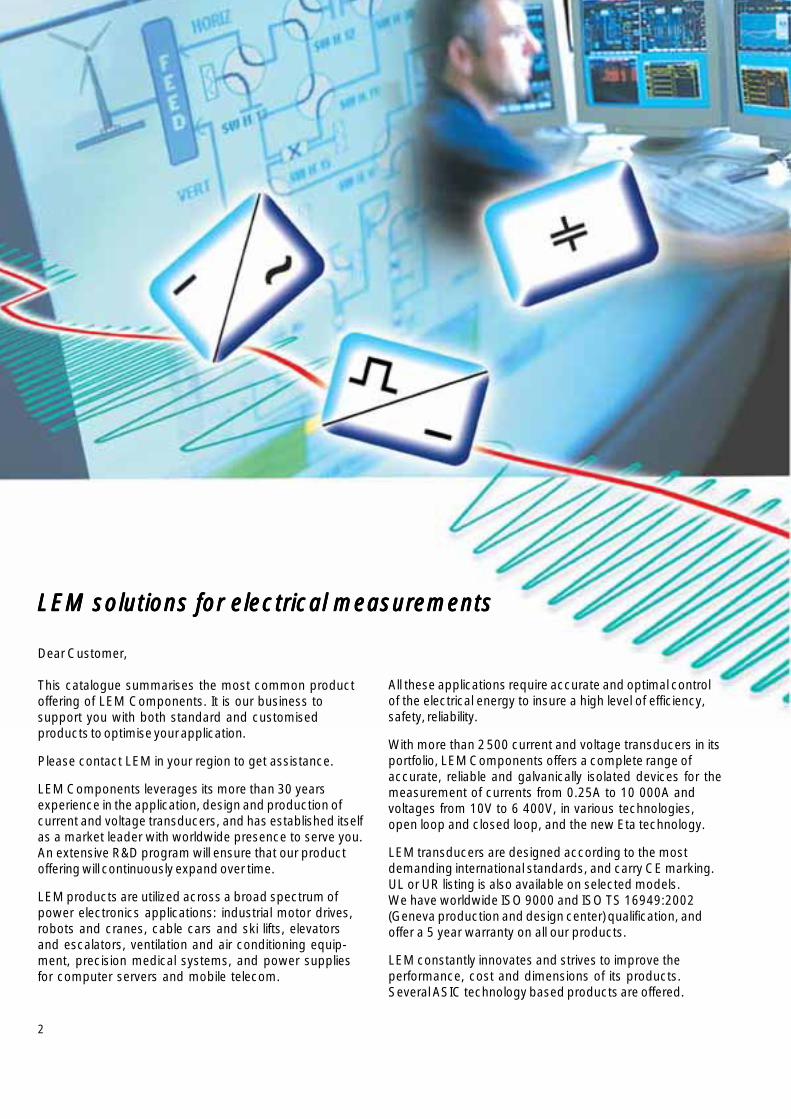
LEM solutions for electrical measurementsLEM solutions for electrical measurementsLEM solutions for electrical measurementsLEM solutions for electrical measurementsLEM solutions for electrical measurements

3
ContentContentContentContentContent
Page
Typical Applications in Power Electronics 4 - 5
Transducer technologies 6 – 7
Current transducers, 0.25 ... 17 A 8 – 9
Current transducers, 20 ... 50 A 10 – 11
Current transducers, 75 ... 300 A (part 1) 12 – 13
Current transducers, 75 ... 300 A (part 2) 14 – 15
Current transducers, 400 ... 800 A 16 – 17
Current transducers, 1 000 ... 20 000 A 18 – 19
Current transducers, 0.01 ... 20 000 A 20 – 21for automation
Voltage transducers, 10 ... 2 500 V 22 – 23(without resistor R1)Voltage transducers, 50 ... 400 V 22 – 23(with built in resistor R1)
Voltage transducers, 500 ... 6 400 V 24 – 25(with built in resistor R1)
Dimension drawings 26 – 35
Product coding 36
Symbols and Terms 36
LEM warranty 37
LEM International 38Sales Network
Selection parameter page
1 Supply voltage 8
2 Frequency response 10
3 Operating temperature range 12
4 Working voltage or rated insulation voltage 14
5 Package and mounting options 16
6 Secondary connections 18
7 Output signal 20
8 Design standards 22
9 Measuring accuracy 24
LEM is a worldwide company, with offices acrossthe globe, and production facilities in Europe, Asiaand America.
We hope you will find this catalogue a useful guidefor the selection of our products. Visit our websitewww.lem.com and contact our sales network forfurther assistance. Detailed data sheet andapplication notes are available.
Sincerely,
Paul Van IseghemPresident LEM Components

44
IL VDC
IDC
IM
IG VDC
IDC
IL
IP
I
IDC
IM
Typical Applicationsin Power Electronics
DC-Link PWM-InverterRectifier orInverter
- Machine tool, printing,paper, textile, plastic
- Steel mill- Lifts- Cranes
Typical ApplicationsTypical ApplicationsTypical ApplicationsTypical ApplicationsTypical Applications
AC Variable Speed Drives and Servo Motor Drives
- Robotics- Pumps- Washing machines
DC-Link PWM-InverterRectifier orInverter
Typical ApplicationsTypical ApplicationsTypical ApplicationsTypical ApplicationsTypical Applications
- Wind mills
Converter
Field Rectifier
Typical ApplicationsTypical ApplicationsTypical ApplicationsTypical ApplicationsTypical Applications
- Machine tool, paper, printing, plastic- Cranes- Escalators- Electrical opening doors systems
Static Converters for DC Motor Drives
Typical ApplicationsTypical ApplicationsTypical ApplicationsTypical ApplicationsTypical Applications
- Electric vehicles(Zero Emission Vehicles, ZEV)
- Fork lift trucks
Battery Inverter
- Wheel chairs- Solar power supplies
Battery Supplied Applications
Charger

5
IVDCIDC
IVDC
IDC
IVDCIDC
AC
DC
Typical applicationsTypical applicationsTypical applicationsTypical applicationsTypical applications
- EDP systems- Telecom- Security systems
UninterruptiblePower Supplies (UPS)
DC-Link InverterCharger Battery
Switched Mode Power Supplies (SMPS)
Typical applicationsTypical applicationsTypical applicationsTypical applicationsTypical applications
- Power supply for electronicequipment and control systems
- Battery chargers- Telecom- Voltage and current stabilizer for
industry and lab applications- Electronic ballast
DC-Link Output RectifierInput Rectifier PWM Inverter
Power Supplies for Welding Applications
DC-Link Output RectifierInput Rectifier PWM Inverter
- Test and measurementin laboratories and universities
- MedicalX-ray and imaging equipment
- Electrolysis, currents monitoring- Inductive heating
Other ApplicationsOther ApplicationsOther ApplicationsOther ApplicationsOther Applications
- Energy management systemsMonitoring of load currents
- Over-current protection- Control and safety systems- Electrical traction

6
Open Loop Current Transducers (O/L)Open Loop Current Transducers (O/L)Open Loop Current Transducers (O/L)Open Loop Current Transducers (O/L)Open Loop Current Transducers (O/L)
FeaturesFeaturesFeaturesFeaturesFeatures
The magnetic flux created by the primary current IP is concentra-
ted in a magnetic circuit and measured in the air gap using a Halldevice. The output from the Hall device is then signal conditionedto provide an exact representation of the primary current at theoutput.
Operation principle O/LOperation principle O/LOperation principle O/LOperation principle O/LOperation principle O/L
Transducer Technologies *
• Small package size• Extended measuring range• Reduced weight• Low power consumption• No insertion losses
Isolated Output Voltage VOUTPrimary Current IP
Closed Loop Current Transducers (C/L)Closed Loop Current Transducers (C/L)Closed Loop Current Transducers (C/L)Closed Loop Current Transducers (C/L)Closed Loop Current Transducers (C/L)
• Wide frequency range• Good overall accuracy• Fast response time• Low temperature drift• Excellent linearity• No insertion losses
FeaturesFeaturesFeaturesFeaturesFeatures
The magnetic flux created by the primary current IP is balanced
by a complementary flux produced by driving a current throughthe secondary windings. A hall device and associated electroniccircuit are used to generate the secondary (compensating)current that is an exact representation of the primary current.
Closed Loop C TypesClosed Loop C TypesClosed Loop C TypesClosed Loop C TypesClosed Loop C Types
FeaturesFeaturesFeaturesFeaturesFeatures
Operation principleOperation principleOperation principleOperation principleOperation principle
This technology uses two toroidal cores and two secondarywindings and operates on the principle of Ampere-turnscompensation. For the voltage type a small (few mA) current istaken from the voltage line to be measured and is driven throughthe primary coil and the primary resistor.
• High accuracy• Very wide frequency range• Reduced temperature drift• Excellent linearity• Measurement of differential currents (CD)• Safety isolation (CV)• Reduced loading on the primary (CV)
Eta technology combines elements from both the Open Loopand Closed Loop principles previously defined. The result is adevice that has the best balance between the features of theboth operating principles.
Eta Current TransducersEta Current TransducersEta Current TransducersEta Current TransducersEta Current Transducers
• Wide bandwidth• Extended measuring range• Very low power consumption• Unipolar power supply 0 ... + 5 V• Fast response time
FeaturesFeaturesFeaturesFeaturesFeatures
Operation principle EtaOperation principle EtaOperation principle EtaOperation principle EtaOperation principle Eta
Operation principle C/LOperation principle C/LOperation principle C/LOperation principle C/LOperation principle C/L
Primary Current IP Isolated Output Current IS
Primary Current IP Isolated Output Voltage VOUT
* for further information, refer the brochure "Characteristics - Applications - Calculations"or get it on www.lem.com website
Primary Current IP Isolated Output Current IS
7
VP
Operation principle C/LOperation principle C/LOperation principle C/LOperation principle C/LOperation principle C/L
Primary Current IP Isolated Output Current IS
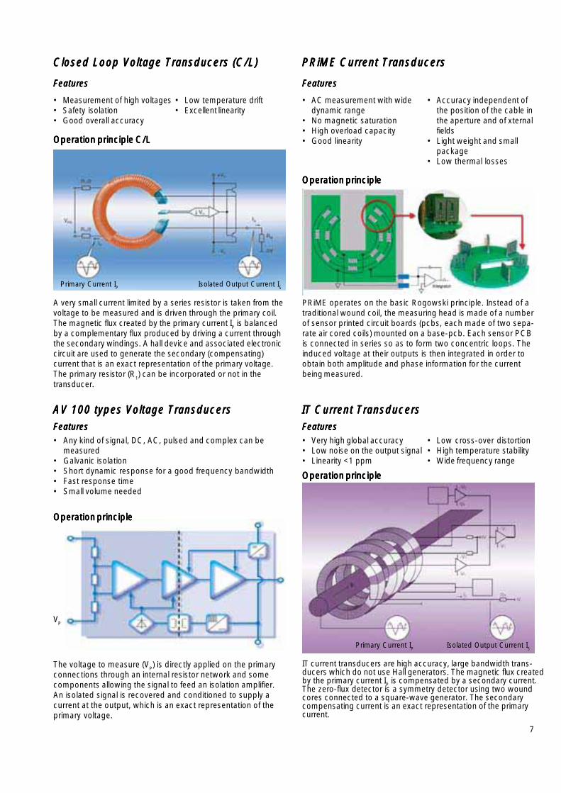
A very small current limited by a series resistor is taken from thevoltage to be measured and is driven through the primary coil.The magnetic flux created by the primary current I
P is balanced
by a complementary flux produced by driving a current throughthe secondary windings. A hall device and associated electroniccircuit are used to generate the secondary (compensating)current that is an exact representation of the primary voltage.The primary resistor (R
1) can be incorporated or not in the
transducer.
Closed Loop Voltage Transducers (C/L)Closed Loop Voltage Transducers (C/L)Closed Loop Voltage Transducers (C/L)Closed Loop Voltage Transducers (C/L)Closed Loop Voltage Transducers (C/L)
FeaturesFeaturesFeaturesFeaturesFeatures
• Measurement of high voltages• Safety isolation• Good overall accuracy
IT Current TransducersIT Current TransducersIT Current TransducersIT Current TransducersIT Current Transducers
FeaturesFeaturesFeaturesFeaturesFeatures
IT current transducers are high accuracy, large bandwidth trans-ducers which do not use Hall generators. The magnetic flux createdby the primary current IP is compensated by a secondary current.The zero-flux detector is a symmetry detector using two woundcores connected to a square-wave generator. The secondarycompensating current is an exact representation of the primarycurrent.
PRiME Current TransducersPRiME Current TransducersPRiME Current TransducersPRiME Current TransducersPRiME Current Transducers
FeaturesFeaturesFeaturesFeaturesFeatures
PRiME operates on the basic Rogowski principle. Instead of atraditional wound coil, the measuring head is made of a numberof sensor printed circuit boards (pcbs, each made of two sepa-rate air cored coils) mounted on a base-pcb. Each sensor PCBis connected in series so as to form two concentric loops. Theinduced voltage at their outputs is then integrated in order toobtain both amplitude and phase information for the currentbeing measured.
AV 100 types Voltage TransducersAV 100 types Voltage TransducersAV 100 types Voltage TransducersAV 100 types Voltage TransducersAV 100 types Voltage Transducers
FeaturesFeaturesFeaturesFeaturesFeatures
The voltage to measure (VP) is directly applied on the primaryconnections through an internal resistor network and somecomponents allowing the signal to feed an isolation amplifier.An isolated signal is recovered and conditioned to supply acurrent at the output, which is an exact representation of theprimary voltage.
Operation principleOperation principleOperation principleOperation principleOperation principle
Operation principleOperation principleOperation principleOperation principleOperation principle
• Very high global accuracy• Low noise on the output signal• Linearity <1 ppm
Operation principleOperation principleOperation principleOperation principleOperation principle
• Any kind of signal, DC, AC, pulsed and complex can bemeasured
• Galvanic isolation• Short dynamic response for a good frequency bandwidth • Fast response time • Small volume needed
• Low cross-over distortion• High temperature stability• Wide frequency range
• AC measurement with widedynamic range
• No magnetic saturation• High overload capacity• Good linearity
• Accuracy independent ofthe position of the cable inthe aperture and of xternalfields
• Light weight and smallpackage
• Low thermal losses
• Low temperature drift• Excellent linearity
Primary Current IP Isolated Output Current IS

8
1
23
10
23
27
226
5
87
4
Selection parameter 1: Supply voltage Selection parameter 1: Supply voltage Selection parameter 1: Supply voltage Selection parameter 1: Supply voltage Selection parameter 1: Supply voltage
Current Transducers
The use of auto insertion equipment in the manufacturingof electronic assemblies is commonplace today. LEMproduces several types of PCB mounted transducersthat are designed with automated assembly in mind.These devices allow our customers to take advantage ofhigh volume production strategies giving them theadvantage necessary to remain competitive.
Designed for automated assemblyDesigned for automated assemblyDesigned for automated assemblyDesigned for automated assemblyDesigned for automated assembly
In addition to the benefit of automated assembly that anintegrated primary bus bar offers, it also has an importantimpact on the performance of the product. By locatingthe primary conductor in exactly the right place in relationto the secondary winding, we maximize the primary tosecondary coupling of the transducer. This givestransducers their excellent high frequency properties.
The current transducer, weighing only 10 g, requires only a small area onthe printed circuit board, and is optimally suited for automated productionlines.
Smallest PackagesSmallest PackagesSmallest PackagesSmallest PackagesSmallest Packages
Most current transducers are still designed for bipolarsupply voltages. This means that the integratedelectronics are supplied with both positive and negativepotentials with reference to ground (0V).
VC = 0, ±12V; 0, ±15V; 0, ±24V; etc.
The new generations of ASIC based transducers operateon a single unipolar supply with reference to ground (0V).
VC = 0 ... +5 V →This option allows the user to save cost by removing theneed for dual supply.
It is important when choosing between the alternativetechnologies to consider the current requirements thattransducers place on their power supplies. Typically, wehave the following current based on the technologyemployed:
Open Loop 20 mAClosed Loop 10 mA + compensation currentEta 16 mAC Type 40 mAIT Type 90 - 200 mA + compensation currentAV 100 Type 50 mA + secondary output currentPRiME 30 mA

9
IIIIIPNPNPNPNPN = 0.25 A ... 17 A = 0.25 A ... 17 A = 0.25 A ... 17 A = 0.25 A ... 17 A = 0.25 A ... 17 A
IPN IP VC VOUT f X TA Connection TypeIOUT @ IPN Primary Sec.
TA =@ IPN 25°C
A A V kHz % °C No.
3 ± 9 O/L ±12…15 4 V DC-50 (-3dB)② 2.4 -25...+85 ●●●●● ●●●●● 1 HX 03-PHX 03-PHX 03-PHX 03-PHX 03-P
3 ± 9 O/L +12…15 2.5 V±0.625 V DC-50 (-3dB)② 2.6 -25...+85 ●●●●● ●●●●● 2 HX 03-P/SP2HX 03-P/SP2HX 03-P/SP2HX 03-P/SP2HX 03-P/SP2
5 ±15 O/L ±12…15 4 V DC-50 (-3dB)② 2.4 -25...+85 ●●●●● ●●●●● 1 HX 05-PHX 05-PHX 05-PHX 05-PHX 05-P
5 ±15 O/L +12…15 2.5 V±0.625 V DC-50 (-3dB)② 2.6 -25...+85 ●●●●● ●●●●● 2 HX 05-P/SP2HX 05-P/SP2HX 05-P/SP2HX 05-P/SP2HX 05-P/SP2
5 ±15 O/L ±12…15 4 V DC-50 (-3dB)② 2.4 -25...+85 ●●●●● ●●●●● 3 HX 05-NP HX 05-NP HX 05-NP HX 05-NP HX 05-NP ④
5 ±15 O/L +5/0 2.5V or VRef ±0.625V DC-50 (-3dB)② 1.5 -40...+85 ●●●●● ●●●●● 4 HXS 20-NPHXS 20-NPHXS 20-NPHXS 20-NPHXS 20-NP
5 ±15 O/L +5/0 2.5V or VRef ±0.625V DC-50 (-3dB)② 1.5 -40...+105 ●●●●● ●●●●● 4 HXS 20-NP/SP2HXS 20-NP/SP2HXS 20-NP/SP2HXS 20-NP/SP2HXS 20-NP/SP2
10 ±15 O/L +5/0 VC/2V±VC • 0.2V① DC-16 (-3dB)② 31 -40...+85 ●●●●● ●●●●● ●●●●● 5 HTS 10-PHTS 10-PHTS 10-PHTS 10-PHTS 10-P
10 ±15 O/L +5/0 VC/2V±VC • 0.2V① DC-16 (-3dB)② 20.5 -40...+85 ●●●●● ●●●●● ●●●●● 5 HTS 10-P/SP1HTS 10-P/SP1HTS 10-P/SP1HTS 10-P/SP1HTS 10-P/SP1
10 ±30 O/L ±12…15 4 V DC-50 (-3dB)② 2.4 -25...+85 ●●●●● ●●●●● 1 HX 10-PHX 10-PHX 10-PHX 10-PHX 10-P
10 ±30 O/L +12…15 2.5 V±0.625 V DC-50 (-3dB)② 2.6 -25...+85 ●●●●● ●●●●● 2 HX 10-P/SP2HX 10-P/SP2HX 10-P/SP2HX 10-P/SP2HX 10-P/SP2
10 ±30 O/L ±12…15 4 V DC-50 (-3dB)② 2.4 -25...+85 ●●●●● ●●●●● 3 HX 05-NP HX 05-NP HX 05-NP HX 05-NP HX 05-NP ⑤
10 ±30 O/L ±12…15 4 V DC-50 (-3dB)② 2.4 -25...+85 ●●●●● ●●●●● 3 HX 10-NP HX 10-NP HX 10-NP HX 10-NP HX 10-NP ④
10 ±30 O/L +5/0 2.5V or VRef ±0.625V DC-50 (-3dB)② 1.5 -40...+85 ●●●●● ●●●●● 4 HXS 20-NPHXS 20-NPHXS 20-NPHXS 20-NPHXS 20-NP
10 ±30 O/L +5/0 2.5V or VRef ±0.625V DC-50 (-3dB)② 1.5 -40...+105 ●●●●● ●●●●● 4 HXS 20-NP/SP2HXS 20-NP/SP2HXS 20-NP/SP2HXS 20-NP/SP2HXS 20-NP/SP2
12.5 ±37.5 O/L +5/0 2.5V or VRef ±0.625V DC-50 (-3dB)② 1.5 -40...+85 ●●●●● ●●●●● 4 HXS 50-NPHXS 50-NPHXS 50-NPHXS 50-NPHXS 50-NP
12.5 ±37.5 O/L +5/0 2.5V or VRef ±0.625V DC-50 (-3dB)② 1.5 -40...+105 ●●●●● ●●●●● 4 HXS 50-NP/SP2HXS 50-NP/SP2HXS 50-NP/SP2HXS 50-NP/SP2HXS 50-NP/SP2
15 ±45 O/L ±12…15 4 V DC-50 (-3dB)② 2.4 -25…+85 ●●●●● ●●●●● 1 HX 15-PHX 15-PHX 15-PHX 15-PHX 15-P
15 ±45 O/L ±12…15 4 V DC-50 (-3dB)② 2.4 -25…+85 ●●●●● ●●●●● 3 HX 15-NP HX 15-NP HX 15-NP HX 15-NP HX 15-NP ④
15 ±45 O/L +12…15 2.5 V ± 0.625 V DC-50 (-3dB)② 2.6 -25…+85 ●●●●● ●●●●● 2 HX 15-P/SP2HX 15-P/SP2HX 15-P/SP2HX 15-P/SP2HX 15-P/SP2
0.25 ±0.36 C/L ±15 25 mA DC-150 (-1dB) 0.5 -10...+70 ●●●●● ●●●●● 82 LA 25-NP/SP14LA 25-NP/SP14LA 25-NP/SP14LA 25-NP/SP14LA 25-NP/SP14
0.5 ±0.72 C/L ±15 25 mA DC-150 (-1dB) 0.5 -40...+70 ●●●●● ●●●●● 82 LA 25-NP/SP13LA 25-NP/SP13LA 25-NP/SP13LA 25-NP/SP13LA 25-NP/SP13
1 ±1.5 C/L ±15 25 mA DC-150 (-1dB) 0.5 0...+70 ●●●●● ●●●●● 82 LA 25-NP/SP11LA 25-NP/SP11LA 25-NP/SP11LA 25-NP/SP11LA 25-NP/SP11
1.5 ±2.2 C/L ±15 24 mA DC-150 (-1dB) 0.5 0...+70 ●●●●● ●●●●● 82 LA 25-NP/SP9LA 25-NP/SP9LA 25-NP/SP9LA 25-NP/SP9LA 25-NP/SP9
2 ±3 C/L ±15 24 mA DC-150 (-1dB) 0.5 0...+70 ●●●●● ●●●●● 82 LA 25-NP/SP8LA 25-NP/SP8LA 25-NP/SP8LA 25-NP/SP8LA 25-NP/SP8
2.5 ±3.6 C/L ±15 25 mA DC-150 (-1dB) 0.5 0...+70 ●●●●● ●●●●● 82 LA 25-NP/SP7LA 25-NP/SP7LA 25-NP/SP7LA 25-NP/SP7LA 25-NP/SP7
5 ±7 C/L ±15 25 mA DC-150 (-1dB) 0.5 -40...+85 ●●●●● ●●●●● 6 LA 25-NPLA 25-NPLA 25-NPLA 25-NPLA 25-NP
6 ±9 C/L ±15 24 mA DC-150 (-1dB) 0.5 -40...+85 ●●●●● ●●●●● 6 LA 25-NPLA 25-NPLA 25-NPLA 25-NPLA 25-NP
6 ±19.2 C/L +5/0 2.5 V±0.625 V DC-200 (-1dB) 0.7 -40...+85 ●●●●● ●●●●● 7 LTS 6-NPLTS 6-NPLTS 6-NPLTS 6-NPLTS 6-NP
6 ±19.2 C/L +5/0 2.5V or VRef ±0.625V DC-200 (-1dB) 0.7 -40...+85 ●●●●● ●●●●● 8 LTSR 6-NPLTSR 6-NPLTSR 6-NPLTSR 6-NPLTSR 6-NP ⑥
7 ±14 C/L ±15 35 mA DC-150 (-1dB) 0.6 -25...+70 ●●●●● ●●●●● 6 LA 35-NPLA 35-NPLA 35-NPLA 35-NPLA 35-NP
8 ±12 C/L ±15 24 mA DC-150 (-1dB) 0.5 -40...+85 ●●●●● ●●●●● 6 LA 25-NPLA 25-NPLA 25-NPLA 25-NPLA 25-NP
8 ±16 C/L ±15 32 mA DC-150 (-1dB) 0.6 -25...+70 ●●●●● ●●●●● 6 LA 35-NPLA 35-NPLA 35-NPLA 35-NPLA 35-NP
8 ±18 C/L ±12...15 24 mA DC-200 (-1dB) 0.4 -25...+85 ●●●●● ●●●●● 9 LAH 25-NPLAH 25-NPLAH 25-NPLAH 25-NPLAH 25-NP
11 ±22 C/L ±15 33 mA DC-150 (-1dB) 0.6 -25...+70 ●●●●● ●●●●● 6 LA 35-NPLA 35-NPLA 35-NPLA 35-NPLA 35-NP
12 ±18 C/L ±15 24 mA DC-150 (-1dB) 0.5 -40...+85 ●●●●● ●●●●● 6 LA 25-NPLA 25-NPLA 25-NPLA 25-NPLA 25-NP
12 ±27 C/L ±12...15 24 mA DC-200 (-1dB) 0.4 -25...+85 ●●●●● ●●●●● 9 LAH 25-NPLAH 25-NPLAH 25-NPLAH 25-NPLAH 25-NP
15 ±48 C/L +5/0 2.5 V±0.625 V DC-200 (-1dB) 0.7 -40...+85 ●●●●● ●●●●● 7 LTS 15-NPLTS 15-NPLTS 15-NPLTS 15-NPLTS 15-NP
15 ±48 C/L +5/0 2.5V or VRef ±0.625V DC-200 (-1dB) 0.7 -40...+85 ●●●●● ●●●●● 8 LTSR 15-NP LTSR 15-NP LTSR 15-NP LTSR 15-NP LTSR 15-NP ⑥
17 ±34 C/L ±15 34 mA DC-150 (-1dB) 0.6 -25...+70 ●●●●● ●●●●● 6 LA 35-NPLA 35-NPLA 35-NPLA 35-NPLA 35-NP
1 ±2 "C“ ±15 5 V DC-500 (-3dB) 0.25③ -25...+70 ●●●●● ●●●●● 10 CT 1-TCT 1-TCT 1-TCT 1-TCT 1-T
2 ±4 "C“ ±15 5 V DC-500 (-3dB) 0.15③ -25...+70 ●●●●● ●●●●● 10 CT 2-TCT 2-TCT 2-TCT 2-TCT 2-T
5 ±7.5 "C“ ±15 5 V DC-500 (-3dB) 0.1③ -25...+70 ●●●●● ●●●●● 10 CT 5-TCT 5-TCT 5-TCT 5-TCT 5-T
10 ±15 "C“ ±15 5 V DC-500 (-3dB) 0.1③ -25...+70 ●●●●● ●●●●● 10 CT 10-TCT 10-TCT 10-TCT 10-TCT 10-T
① output is ratiometric ② Small signal bandwidth to avoid excessive core heating at high frequency. ③ Global accuracy within theoperating temperature range. ④ Connected in series, ⑤ Connected in parallel, ⑥ Refin & Refout modes, recognized, on the way tobe recognized
Open-loop Closed-loop "C"-types
Tec
hno
log
yT
echn
olo
gy
Tec
hno
log
yT
echn
olo
gy
Tec
hno
log
y
Datasheets: wwwDatasheets: wwwDatasheets: wwwDatasheets: wwwDatasheets: www.lem.com.lem.com.lem.com.lem.com.lem.com
Pac
kagi
ngP
acka
ging
Pac
kagi
ngP
acka
ging
Pac
kagi
ng
PC
BP
CB
PC
BP
CB
PC
B
Ape
rture
, bus
-ba
r, oth
er
PC
BP
CB
PC
BP
CB
PC
B
Oth
erO
ther
Oth
erO
ther
Oth
er

10
1 23
2126 9
28
25
13
2412 15
16
1917
1820
Current Transducers
Selection parameter 2: Frequency response Selection parameter 2: Frequency response Selection parameter 2: Frequency response Selection parameter 2: Frequency response Selection parameter 2: Frequency response
The amount of board space a component occupies isan important design criteria. LEM has developed aseries of transducers that require only a small area onthe circuit board. They use if possible, the same housingor similar packaging for different current ranges. For theuser, this simplifies the development of a completeproduct series covering several power ranges.
Optimum use of spaceOptimum use of spaceOptimum use of spaceOptimum use of spaceOptimum use of space
The compact design of the ASIC-based LTS, LTSR, LASand new HAIS and HXS series transducers, enable usersto take advantage of the intrinsic benefits of isolated Halleffect-based current measurement - high accuracy, fastresponse, and, wide bandwidth - without the usual trade-off in PCB real estate.
The frequency response for LEM transducers is primarilydependent on the type of transducer, i.e. closed or openloop, etc., since within each type there are a number of keyfactors which fundamentally affect the transducersbandwidth.
For open loop transducers, the core geometry, the numberand thickness of the laminations, and the specific core ma-terial have a direct impact on bandwidth.
In the case of closed loop, Eta and IT-type, (and to a lesserextent, C-type) the coupling between the primary andsecondary - which is affected by the particular coregeometry and construction - is the determining factor intransducer bandwidth.
When for the AV 100 Type and PRiME, it's a question ofelectronic limitation.
In general bandwidth is as follows:
• Open Loop DC to 25/50 kHz *• ETA and IT Type DC to 100 kHz (-1dB)• Closed Loop DC to 200 kHz (-1dB)• C Type DC to 500 kHz (-3dB)• AV 100 Type DC to 13 kHz (-3dB)• PRiME AC 10 Hz to 6 kHz (-3dB)
(typically but can go up to several kHz)
* Note: Small signal bandwidth to avoid excessive coreheating at high frequency.
Multiple shapes and sizesMultiple shapes and sizesMultiple shapes and sizesMultiple shapes and sizesMultiple shapes and sizes
Use of ASIC based transducers, LTS series, in an inverter for control andprotection.

11
IIIIIPNPNPNPNPN = 20 A ... 50 A = 20 A ... 50 A = 20 A ... 50 A = 20 A ... 50 A = 20 A ... 50 A"C"-typesOpen-loop Closed-loop
IPN IP VC VOUT f X TA Connection TypeIOUT @ IPN Primary Sec.
TA =@ IPN 25°C
A A V kHz % °C No.
20 ±60 O/L ±12…15 4 V DC-50 (-3dB)② 2.4 -25…+85 ●●●●● ●●●●● 1 HX 20-PHX 20-PHX 20-PHX 20-PHX 20-P
20 ±60 O/L ±12…15 4 V DC-50 (-3dB)② 2.4 -25…+85 ●●●●● ●●●●● 3 HX 10-NPHX 10-NPHX 10-NPHX 10-NPHX 10-NP ⑤
20 ±60 O/L +12…15 2.5 V ± 0.625 V DC-50 (-3dB)② 2.6 -25…+85 ●●●●● ●●●●● 2 HX 20-P/SP2HX 20-P/SP2HX 20-P/SP2HX 20-P/SP2HX 20-P/SP2
20 ±60 O/L +5/0 2.5V or VRef ±0.625V DC-50 (-3dB)② 1.5 -40...+85 ●●●●● ●●●●● 4 HXS 20-NPHXS 20-NPHXS 20-NPHXS 20-NPHXS 20-NP
20 ±60 O/L +5/0 2.5V or VRef ±0.625V DC-50 (-3dB)② 1.5 -40...+105 ●●●●● ●●●●● 4 HXS 20-NP/SP2HXS 20-NP/SP2HXS 20-NP/SP2HXS 20-NP/SP2HXS 20-NP/SP2
25 ±75 O/L ±12…15 4 V DC-50 (-3dB)② 2.4 -25…+85 ●●●●● ●●●●● 1 HX 25-PHX 25-PHX 25-PHX 25-PHX 25-P
25 ±75 O/L +12...15 2.5 V±0.625 V DC-50 (-3dB)② 2.6 -25...+85 ●●●●● ●●●●● 2 HX 25-P/SP2HX 25-P/SP2HX 25-P/SP2HX 25-P/SP2HX 25-P/SP2
25 ±75 O/L +5/0 2.5V or VRef ±0.625V DC-50 (-3dB)② 1.5 -40...+85 ●●●●● ●●●●● 4 HXS 50-NPHXS 50-NPHXS 50-NPHXS 50-NPHXS 50-NP
25 ±75 O/L +5/0 2.5V or VRef ±0.625V DC-50 (-3dB)② 1.5 -40...+105 ●●●●● ●●●●● 4 HXS 50-NP/SP2HXS 50-NP/SP2HXS 50-NP/SP2HXS 50-NP/SP2HXS 50-NP/SP2
30 ±90 O/L ±12…15 4 V DC-50 (-3dB)② 2.4 -25…+85 ●●●●● ●●●●● 3 HX 15-NPHX 15-NPHX 15-NPHX 15-NPHX 15-NP ⑤
50 ±100 O/L ±12...15 4 V DC-10 (-1dB)② 3.4 -10...+70 ●●●●● ●●●●● 11 HTR 50-SBHTR 50-SBHTR 50-SBHTR 50-SBHTR 50-SB
50 ±150 O/L +5/0 2.5V or VRef ±0.625V DC-50 (-3dB)② 2.3 -40...+85 ●●●●● ●●●●● 12 HAIS 50-P HAIS 50-P HAIS 50-P HAIS 50-P HAIS 50-P ③
50 ±150 O/L +5/0 2.5V or VRef ±0.625V DC-50 (-3dB)② 2.3 -40...+85 ●●●●● ●●●●● 13 HAIS 50-TP HAIS 50-TP HAIS 50-TP HAIS 50-TP HAIS 50-TP ③
50 ±150 O/L ±15 4 V DC-50 (-3dB) ② 1.75 -25...+85 ●●●●● ●●●●● 14 HAL 50-SHAL 50-SHAL 50-SHAL 50-SHAL 50-S
50 ±150 O/L ±15 4 V DC-50 (-3dB) ② 3 -10...+80 ●●●●● ●●●●● 15 HAS 50-SHAS 50-SHAS 50-SHAS 50-SHAS 50-S
50 ±150 O/L +5/0 VC/2 V ± 0.5 V DC-50 (-3dB)② 4 -10...+80 ●●●●● ●●●●● 16 HAS 50-S/SP1HAS 50-S/SP1HAS 50-S/SP1HAS 50-S/SP1HAS 50-S/SP1
50 ±150 O/L ±12...15 4 V DC-50 (-3dB) ② 2.7 -20...+80 ●●●●● ●●●●● 17 HTB 50-PHTB 50-PHTB 50-PHTB 50-PHTB 50-P
50 ±150 O/L ±12…15 4 V DC-50 (-3dB)② 2.7 -20...+80 ●●●●● ●●●●● 18 HTB 50-TPHTB 50-TPHTB 50-TPHTB 50-TPHTB 50-TP
50 ±150 O/L +12…15 VC/2 V±1.667 V DC-50 (-3dB)② 1.5 -25...+85 ●●●●● ●●●●● 19 HTB 50-P/SP5HTB 50-P/SP5HTB 50-P/SP5HTB 50-P/SP5HTB 50-P/SP5
50 ±150 O/L +12…15 VC/2 V±1.667 V DC-50 (-3dB)② 1.5 -25...+85 ●●●●● ●●●●● 20 HTB 50-TP/SP5HTB 50-TP/SP5HTB 50-TP/SP5HTB 50-TP/SP5HTB 50-TP/SP5
50 ±150 O/L ±15 4 V DC-50 (-3dB) ② 2.2 -10...+75 ●●●●● ●●●●● 21 HTY 50-PHTY 50-PHTY 50-PHTY 50-PHTY 50-P
50 ±150 O/L ±12…15 4 V DC-50 (-3dB)② 2.4 -25...+85 ●●●●● ●●●●● 1 HX 50-PHX 50-PHX 50-PHX 50-PHX 50-P
50 ±150 O/L +12...15 2.5 V±0.625 V DC-50 (-3dB)② 2.6 -25...+85 ●●●●● ●●●●● 2 HX 50-P/SP2HX 50-P/SP2HX 50-P/SP2HX 50-P/SP2HX 50-P/SP2
50 ±150 O/L +5/0 2.5V or VRef ±0.625V DC-50 (-3dB)② 1.5 -40...+85 ●●●●● ●●●●● 4 HXS 50-NPHXS 50-NPHXS 50-NPHXS 50-NPHXS 50-NP
50 ±150 O/L +5/0 2.5V or VRef ±0.625V DC-50 (-3dB)② 1.5 -40...+105 ●●●●● ●●●●● 4 HXS 50-NP/SP2HXS 50-NP/SP2HXS 50-NP/SP2HXS 50-NP/SP2HXS 50-NP/SP2
25 ±36 C/L ±15 25 mA DC-150 (-1dB) 0.5 -40...+85 ●●●●● ●●●●● 6 LA 25-NPLA 25-NPLA 25-NPLA 25-NPLA 25-NP
25 +36 C/L +15/0 25 mA DC-150 (-1dB) 0.5 0...+70 ●●●●● ●●●●● 22 LA 25-NP/SP2LA 25-NP/SP2LA 25-NP/SP2LA 25-NP/SP2LA 25-NP/SP2
25 ±36 C/L ±15 25 mA DC-150 (-1dB) 0.5 -40...+85 ●●●●● ●●●●● 23 LA 25-NP/SP25LA 25-NP/SP25LA 25-NP/SP25LA 25-NP/SP25LA 25-NP/SP25
25 ±55 C/L ±12...15 25 mA DC-200 (-1dB) 0.4 -25...+85 ●●●●● ●●●●● 9 LAH 25-NPLAH 25-NPLAH 25-NPLAH 25-NPLAH 25-NP
25 ±80 C/L + 5/0 2.5 V±0.625 V DC-200 (-1dB) 0.7 -40...+85 ●●●●● ●●●●● 7 LTS 25-NPLTS 25-NPLTS 25-NPLTS 25-NPLTS 25-NP
25 ±80 C/L +5/0 2.5V or VRef ±0.625V DC-200 (-1dB) 0.7 -40...+85 ●●●●● ●●●●● 8 LTSR 25-NP LTSR 25-NP LTSR 25-NP LTSR 25-NP LTSR 25-NP ③
35 ±70 C/L ±15 35 mA DC-150 (-1dB) 0.6 -25...+70 ●●●●● ●●●●● 6 LA 35-NPLA 35-NPLA 35-NPLA 35-NPLA 35-NP
50 ±70 C/L ±12...15 50 mA DC-200 (-1dB) 0.65⑥ -25...+85 ●●●●● ●●●●● 24 LA 55-PLA 55-PLA 55-PLA 55-PLA 55-P
50 ±70 C/L ±12...15 50 mA DC-200 (-1dB) 0.45⑥ -25...+85 ●●●●● ●●●●● 24 LA 55-P/SP23LA 55-P/SP23LA 55-P/SP23LA 55-P/SP23LA 55-P/SP23
50 ±70 C/L ±12...15 50 mA DC-200 (-1dB) 0.65⑥ -25...+85 ●●●●● ●●●●● 25 LA 55-TPLA 55-TPLA 55-TPLA 55-TPLA 55-TP
50 ±100 C/L ±12...15 25 mA DC-200 (-1dB) 0.65⑥ -25...+85 ●●●●● ●●●●● 24 LA 55-P/SP1LA 55-P/SP1LA 55-P/SP1LA 55-P/SP1LA 55-P/SP1
50 ±100 C/L ±12...15 25 mA DC-200 (-1dB) 0.65⑥ -25...+85 ●●●●● ●●●●● 25 LA 55-TP/SP1LA 55-TP/SP1LA 55-TP/SP1LA 55-TP/SP1LA 55-TP/SP1
50 ±100 C/L ±12...15 25 mA DC-200 (-1dB) 0.65⑥ -40...+85 ●●●●● ●●●●● 25 LA 55-TP/SP27LA 55-TP/SP27LA 55-TP/SP27LA 55-TP/SP27LA 55-TP/SP27
50 ±110 C/L ±12...15 25 mA DC-200 (-1dB) 0.3 -25...+85 ●●●●● ●●●●● 26 LAH 50-PLAH 50-PLAH 50-PLAH 50-PLAH 50-P
25 ±37.5 "C“ ±15 5 V DC-500 (-3dB) 0.1⑦ -25...+70 ●●●●● ●●●●● 10 CT 25-TCT 25-TCT 25-TCT 25-TCT 25-T
50 ±75 "C“ ±15 5 V DC-500 (-3dB) 0.1⑦ -25...+70 ●●●●● ●●●●● 27 CT 50-TCT 50-TCT 50-TCT 50-TCT 50-T
50 ±150 Eta +5/0 2.5V or VRef ±0.625V DC-100 (-1dB) 1.2 -40...+85 ●●●●● ●●●●● 28 LAS 50-TPLAS 50-TPLAS 50-TPLAS 50-TPLAS 50-TP
Tec
hno
log
yT
echn
olo
gy
Tec
hno
log
yT
echn
olo
gy
Tec
hno
log
y
Datasheets: wwwDatasheets: wwwDatasheets: wwwDatasheets: wwwDatasheets: www.lem.com.lem.com.lem.com.lem.com.lem.com
① output is ratiometric, ② Small signal bandwidth to avoid excessive core heating at high frequency. ③ Refout and Refin modes. ⑤ Connected in parallel⑥ Accuracy calculated with max. electrical offset instead of typical electrical offset @ VC = ±15 V. ⑦ Global accuracy within the operating temperaturerange. recognized, on the way to be recognized
Pac
kagi
ngP
acka
ging
Pac
kagi
ngP
acka
ging
Pac
kagi
ng
PC
BP
CB
PC
BP
CB
PC
B
Ape
rture
, bus
-ba
r, oth
er
PC
BP
CB
PC
BP
CB
PC
B
Oth
erO
ther
Oth
erO
ther
Oth
er

12
3239
3829
3534
43
33
31 41
42
11
30
37
36
44 45
52
40
Current Transducers
Selection parameter 3: Operating T Selection parameter 3: Operating T Selection parameter 3: Operating T Selection parameter 3: Operating T Selection parameter 3: Operating Temperature Rangeemperature Rangeemperature Rangeemperature Rangeemperature Range
More accurate measurement results for a smoother ride.
Operating temperature range is a key criteria in theproper transducer selection. The majority of LEMtransducers operate within the following temperatureranges:
-25 °C .. 85 °C-40 °C .. 85 °C
LEM offers a comprehensive range of transducersoptimized for commercial and industrial operatingenvironments. The transducers included in thiscatalogue have various temperatures specificationsrelated to their global accuracy over a specific operatingtemperature range. LEM can also provide transducerswith operating temperature ranges outside the listedselection to fulfill a specific requirement.
VVVVVarious primararious primararious primararious primararious primary conductor optionsy conductor optionsy conductor optionsy conductor optionsy conductor options
For nominal current levels greater than 100 Amps, PCBmounting is not a viable option for the primary. ThereforeLEM has designed a wide range of closed and openloop panel mounted current transducers. They arehoused in common package outlines to accommodatea number of primary conductor options.
Multiple mounting possibilitiesMultiple mounting possibilitiesMultiple mounting possibilitiesMultiple mounting possibilitiesMultiple mounting possibilities
In addition to standard configurations, LEM cancustomize the integrated primary bus-bar to meet yoursystems specific requirements. Let our experience inproviding current and voltage transducers for theharshest shock and vibration environments assist you inyour transducer selection.

13
IIIIIPNPNPNPNPN = 75 A ... 300 A = 75 A ... 300 A = 75 A ... 300 A = 75 A ... 300 A = 75 A ... 300 A (part 1)
IPN IP VC VOUT f X TA Connection TypeIOUT @ IPN Primary Sec.
TA =@ IPN 25°C
A A V kHz % °C No.
75 ±225 O/L ±15 4 V DC-50 (-3dB) ① 2.2 -10...+75 ●●●●● ●●●●● 21 HTY 75-PHTY 75-PHTY 75-PHTY 75-PHTY 75-P
100 ±300 O/L ±15 4 V DC-50 (-3dB) ① 2.7 -10...+80 ●●●●● ●●●●● 29 HAC 100-SHAC 100-SHAC 100-SHAC 100-SHAC 100-S
100 ±300 O/L +5/0 2.5V or VRef ±0.625V DC-50 (-3dB) ① 2.3 -40...+85 ●●●●● ●●●●● 12 HAIS 100-P HAIS 100-P HAIS 100-P HAIS 100-P HAIS 100-P ②
100 ±300 O/L +5/0 2.5V or VRef ±0.625V DC-50 (-3dB) ① 2.3 -40...+85 ●●●●● ●●●●● 13 HAIS 100-TP HAIS 100-TP HAIS 100-TP HAIS 100-TP HAIS 100-TP ②
100 ±300 O/L ±15 4 V DC-50 (-3dB) ① 1.75 -25...+85 ●●●●● ●●●●● 14 HAL 100-SHAL 100-SHAL 100-SHAL 100-SHAL 100-S
100 ±300 O/L ±15 4 V DC-50 (-3dB) ① 3 -10...+80 ●●●●● ●●●●● 15 HAS 100-SHAS 100-SHAS 100-SHAS 100-SHAS 100-S
100 ±300 O/L +5/0 VC/2 V±0.5 V DC-50 (-3dB) ① 4 -10...+80 ●●●●● ●●●●● 16 HAS 100-S/SP1HAS 100-S/SP1HAS 100-S/SP1HAS 100-S/SP1HAS 100-S/SP1
100 ±300 O/L ±15 4 V DC-50 (-3dB) ① 1.75 -25...+85 ●●●●● ●●●●● 30 HTA 100-SHTA 100-SHTA 100-SHTA 100-SHTA 100-S
100 ±300 O/L ±12...15 4 V DC-50 (-3dB) ① 2.7 -20...+80 ●●●●● ●●●●● 17 HTB 100-PHTB 100-PHTB 100-PHTB 100-PHTB 100-P
100 ±300 O/L ±12..15 4 V DC-50 (-3dB)① 2.7 -20...+80 ●●●●● ●●●●● 18 HTB 100-TPHTB 100-TPHTB 100-TPHTB 100-TPHTB 100-TP
100 ±300 O/L +12…15 VC/2 V±1.667 V DC-50 (-3dB)① 1.5 -25...+85 ●●●●● ●●●●● 19 HTB 100-P/SP5HTB 100-P/SP5HTB 100-P/SP5HTB 100-P/SP5HTB 100-P/SP5
100 ±300 O/L +12…15 VC/2 V±1.667 V DC-50 (-3dB)① 1.5 -25...+85 ●●●●● ●●●●● 20 HTB 100-TP/SP5HTB 100-TP/SP5HTB 100-TP/SP5HTB 100-TP/SP5HTB 100-TP/SP5
100 ±200 O/L ±12..15 4 V DC-10 (-1dB)① 3.4 -10...+70 ●●●●● ●●●●● 11 HTR 100-SBHTR 100-SBHTR 100-SBHTR 100-SBHTR 100-SB
100 ±300 O/L ±15 4 V DC-50 (-3dB)① 2.2 -10...+75 ●●●●● ●●●●● 21 HTY 100-PHTY 100-PHTY 100-PHTY 100-PHTY 100-P
150 ±450 O/L +5/0 2.5V or VRef ±0.625V DC-50 (-3dB)① 2.3 -40...+85 ●●●●● ●●●●● 12 HAIS 150-P HAIS 150-P HAIS 150-P HAIS 150-P HAIS 150-P ②
200 ±600 O/L ±15 4 V DC-50 (-3dB)① 2.7 -10...+80 ●●●●● ●●●●● 29 HAC 200-SHAC 200-SHAC 200-SHAC 200-SHAC 200-S
200 ±600 O/L +5/0 2.5V or VRef ±0.625V DC-50 (-3dB)① 2.3 -40...+85 ●●●●● ●●●●● 12 HAIS 200-P HAIS 200-P HAIS 200-P HAIS 200-P HAIS 200-P ②
200 ±600 O/L ±15 4 V DC-50 (-3dB)① 1.75 -25...+85 ●●●●● ●●●●● 14 HAL 200-SHAL 200-SHAL 200-SHAL 200-SHAL 200-S
200 ±600 O/L ±15 4 V DC-50 (-3dB)① 3 -10...+80 ●●●●● ●●●●● 15 HAS 200-SHAS 200-SHAS 200-SHAS 200-SHAS 200-S
200 ±600 O/L +5/0 VC/2 V±0.5 V DC-50 (-3dB)① 4 -10...+80 ●●●●● ●●●●● 16 HAS 200-S/SP1HAS 200-S/SP1HAS 200-S/SP1HAS 200-S/SP1HAS 200-S/SP1
200 ±300 O/L ±12..15 4 V DC-8 (-1dB)① 3.75 -10...+70 ●●●●● ●●●●● 31 HOP 200-SBHOP 200-SBHOP 200-SBHOP 200-SBHOP 200-SB
200 ±600 O/L ±15 4 V DC-50 (-3dB)① 1.75 -25...+85 ●●●●● ●●●●● 30 HTA 200-SHTA 200-SHTA 200-SHTA 200-SHTA 200-S
200 ±500 O/L ±12...15 4 V DC-50 (-3dB)① 2.7 -20...+80 ●●●●● ●●●●● 17 HTB 200-PHTB 200-PHTB 200-PHTB 200-PHTB 200-P
200 ±500 O/L +12…15 VC/2 V±1.667 V DC-50 (-3dB)① 1.5 -25...+85 ●●●●● ●●●●● 19 HTB 200-P/SP5HTB 200-P/SP5HTB 200-P/SP5HTB 200-P/SP5HTB 200-P/SP5
200 ±400 O/L ±12..15 4 V DC-10 (-1dB)① 3.4 -10...+70 ●●●●● ●●●●● 11 HTR 200-SBHTR 200-SBHTR 200-SBHTR 200-SBHTR 200-SB
300 ±900 O/L ±15 4 V DC-50 (-3dB)① 2.7 -10...+80 ●●●●● ●●●●● 29 HAC 300-SHAC 300-SHAC 300-SHAC 300-SHAC 300-S
300 ±900 O/L ±15 4 V DC-50 (-3dB)① 1.75 -25...+85 ●●●●● ●●●●● 14 HAL 300-SHAL 300-SHAL 300-SHAL 300-SHAL 300-S
300 ±900 O/L ±15 4 V DC-50 (-3dB)① 3 -10...+80 ●●●●● ●●●●● 15 HAS 300-SHAS 300-SHAS 300-SHAS 300-SHAS 300-S
300 ±900 O/L +5/0 VC/2 V±0.5 V DC-50 (-3dB)① 4 -10...+80 ●●●●● ●●●●● 16 HAS 300-S/SP1HAS 300-S/SP1HAS 300-S/SP1HAS 300-S/SP1HAS 300-S/SP1
300 ±450 O/L ±12..15 4 V DC-8 (-1dB)① 3.75 -10...+70 ●●●●● ●●●●● 31 HOP 300-SBHOP 300-SBHOP 300-SBHOP 300-SBHOP 300-SB
300 ±900 O/L ±15 4 V DC-50 (-3dB)① 1.75 -25...+85 ●●●●● ●●●●● 30 HTA 300-SHTA 300-SHTA 300-SHTA 300-SHTA 300-S
300 ±600 O/L ±12..15 4 V DC-10 (-1dB)① 3.4 -10...+70 ●●●●● ●●●●● 11 HTR 300-SBHTR 300-SBHTR 300-SBHTR 300-SBHTR 300-SB
300 ±600 O/L ±12...15 4 V DC-50 (-3dB)① 2.7 -20...+80 ●●●●● ●●●●● 17 HTB 300-PHTB 300-PHTB 300-PHTB 300-PHTB 300-P
300 ±600 O/L +12…15 VC/2 V±1.667 V DC-50 (-3dB)① 1.5 -25...+85 ●●●●● ●●●●● 19 HTB 300-P/SP5HTB 300-P/SP5HTB 300-P/SP5HTB 300-P/SP5HTB 300-P/SP5
Tec
hno
log
yT
echn
olo
gy
Tec
hno
log
yT
echn
olo
gy
Tec
hno
log
y
① Small signal bandwidth to avoid excessive core heating at high frequency.② Refout & Refin modes.
recognizedon the way to be recognized
Open-loop
Datasheets: wwwDatasheets: wwwDatasheets: wwwDatasheets: wwwDatasheets: www.lem.com.lem.com.lem.com.lem.com.lem.com
PC
BP
CB
PC
BP
CB
PC
B
Ape
rture
, bus
-ba
r, oth
er
PC
BP
CB
PC
BP
CB
PC
B
Oth
erO
ther
Oth
erO
ther
Oth
er Pac
kagi
ngP
acka
ging
Pac
kagi
ngP
acka
ging
Pac
kagi
ng

14
28
25
24
35
43
33
42
41
5153
37
36
44 45
52
34
39
32
26
38 40
Current Transducers
Selection parameter 4: W Selection parameter 4: W Selection parameter 4: W Selection parameter 4: W Selection parameter 4: Working Vorking Vorking Vorking Vorking Voltage or Rated Insulation Voltage or Rated Insulation Voltage or Rated Insulation Voltage or Rated Insulation Voltage or Rated Insulation Voltageoltageoltageoltageoltage
Working Voltage level allowed by a transducer intended tobe used in an application classified as being "Industrial" isdefined according to several criteria defined under the EN50178 standard. Some are dependent of the transduceritself when the others are linked to the application.
These criteria are the followings:• Clearance distance• Creepage distance• Pollution degree (of the application)• Overvoltage category (of the application)
• Comparative Tracking Index (CTI linked to the kind ofmaterial used for the transducer case) leading to aclassification over different Insulating Material groups
• Simple or Reinforced isolation need.
LEM transducers follow this thought process for theirdesigns. For PCB mounting transducers, the customerPCB tracks layout has to be taken into account to findthe possible working voltage. Indeed, the clearance andcreepage distances can be different according to thecustomer PCB layout.
From PCB to panel mountingFrom PCB to panel mountingFrom PCB to panel mountingFrom PCB to panel mountingFrom PCB to panel mounting
Quality is requested by everyone and it is quite justified.The levels required by customers can be different according tothe applications. This quality has to be reached but also main-tained in the time and constantly improved as well as forproducts than for services. The different LEM design andproduction centers around the world are either ISO TS 16949,and/or ISO 9001 and/or ISO 14001 certified.
LEM qualityLEM qualityLEM qualityLEM qualityLEM quality
Several quality tools have been implemented in LEM to assessand analyze its performances to be able to take the necessaryactions to remain a responsive player in the market.Among which the most representatives are :
- DPT FMEA (Design Process Tool & Failure Mode Effect Analysis)- Control Plan- Cpk – R&R (Capability for Processes & measurement systems)- QOS – 8D (Quality Operating System – Eight Disciplines)- IPQ (Interactive Purchase Questionnaire).
In addition to these quality programs and since 2002, LEMembraces Six Sigma as its methodology in pursuit of businessexcellence. The main goal is to create an environment in whichanything less than Six Sigma quality is unacceptable.

15
IIIIIPNPNPNPNPN = 75 A ... 300 A = 75 A ... 300 A = 75 A ... 300 A = 75 A ... 300 A = 75 A ... 300 A (part 2)
IPN IP VC VOUT f X TA Connection TypeIOUT @ IPN Primary Sec.
TA =@ IPN 25°C
A A V kHz % °C No.
100 ±150 C/L ±12...15 50 mA DC-200 (-1dB) 0.45③ -40...+85 ●●●●● ●●●●● 24 LA 100-PLA 100-PLA 100-PLA 100-PLA 100-P
100 ±150 C/L ±12...15 50 mA DC-200 (-1dB) 0.45③ -40...+85 ●●●●● ●●●●● 25 LA 100-TPLA 100-TPLA 100-TPLA 100-TPLA 100-TP
100 ±160 C/L ±12...15 50 mA DC-200 (-1dB) 0.3 -25...+85 ●●●●● ●●●●● 26 LAH 100-PLAH 100-PLAH 100-PLAH 100-PLAH 100-P
100 ±160 C/L ±12...15 100 mA DC-200 (-1dB) 0.45③ -25...+70 ●●●●● ●●●●● 24 LA 100-P/SP13LA 100-P/SP13LA 100-P/SP13LA 100-P/SP13LA 100-P/SP13
100 ±200 C/L ±12..15 100 mA DC-100 (-3dB) 0.4 -40...+85 ●●●●● ●●●●● 32 LF 205-S/SP3LF 205-S/SP3LF 205-S/SP3LF 205-S/SP3LF 205-S/SP3
125 ±200 C/L ±12...15 125 mA DC-100 (-1dB) 0.8 -40...+85 ●●●●● ●●●●● 33 LA 125-PLA 125-PLA 125-PLA 125-PLA 125-P
125 ±200 C/L ±12...15 62.5 mA DC-100 (-1dB) 0.8 -25...+85 ●●●●● ●●●●● 33 LA 125-P/SP1LA 125-P/SP1LA 125-P/SP1LA 125-P/SP1LA 125-P/SP1
125 ±300 C/L ±12...15 62.5 mA DC-100 (-1dB) 0.8 -40...+85 ●●●●● ●●●●● 33 LA 125-P/SP4LA 125-P/SP4LA 125-P/SP4LA 125-P/SP4LA 125-P/SP4
125 ±200 C/L ±12...15 125 mA DC-100 (-3dB) 0.41 -40...+85 ●●●●● ●●●●● 34 LAH 125-PLAH 125-PLAH 125-PLAH 125-PLAH 125-P
150 ±200 C/L ±15 75 mA DC-150 (-1dB)① 0.85 -10...+80 ●●●●● ●●●●● 35 LA 150-PLA 150-PLA 150-PLA 150-PLA 150-P
200 ±300 C/L ±12...15 100 mA DC-100 (-1dB) 0.65 -40...+85 ●●●●● ●●●●● 33 LA 200-PLA 200-PLA 200-PLA 200-PLA 200-P
200 ±300 C/L ±12...15 100 mA DC-100 (-1dB) 0.65 -25...+85 ●●●●● ●●●●● 33 LA 200-P/SP4LA 200-P/SP4LA 200-P/SP4LA 200-P/SP4LA 200-P/SP4
200 ±300 C/L ±12...15 100 mA DC-100 (-3dB) 0.3 -10...+85 ●●●●● ●●●●● 36 LA 205-SLA 205-SLA 205-SLA 205-SLA 205-S
200 ±300 C/L ±12...15 100 mA DC-100 (-3dB) 0.3 -10...+85 ●●●●● ●●●●● 36 LA 205-S/SP1LA 205-S/SP1LA 205-S/SP1LA 205-S/SP1LA 205-S/SP1
200 ±300 C/L ±12...15 100 mA DC-100 (-3dB) 0.3 -10...+85 ●●●●● ●●●●● 37 LA 205-TLA 205-TLA 205-TLA 205-TLA 205-T
200 ±420 C/L ±12...15 100 mA DC-100 (-3dB) 0.4 -40...+85 ●●●●● ●●●●● 32 LF 205-SLF 205-SLF 205-SLF 205-SLF 205-S
200 ±420 C/L ±12...15 100 mA DC-100 (-3dB) 0.4 -40...+85 ●●●●● ●●●●● 38 LF 205-PLF 205-PLF 205-PLF 205-PLF 205-P
200 ±420 C/L ±12...15 100 mA DC-100 (-3dB) 0.4 -40...+85 ●●●●● ●●●●● 39 LF 205-S/SP1LF 205-S/SP1LF 205-S/SP1LF 205-S/SP1LF 205-S/SP1
200 ±420 C/L ±12...15 100 mA DC-100 (-3dB) 0.4 -40...+85 ●●●●● ●●●●● 40 LF 205-P/SP1LF 205-P/SP1LF 205-P/SP1LF 205-P/SP1LF 205-P/SP1
250 ±500 C/L ±12...18 125 mA DC-100 (-3dB) 0.3 -10...+85 ●●●●● ●●●●● 41 LA 255-SLA 255-SLA 255-SLA 255-SLA 255-S
250 ±500 C/L ±12...18 125 mA DC-100 (-3dB) 0.3 -10...+85 ●●●●● ●●●●● 42 LA 255-TLA 255-TLA 255-TLA 255-TLA 255-T
300 ±500 C/L ±12...15 150 mA DC-100 (-3dB) 0.3 -10...+85 ●●●●● ●●●●● 43 LA 205-S/SP30LA 205-S/SP30LA 205-S/SP30LA 205-S/SP30LA 205-S/SP30
300 ±500 C/L ±12...15 120 mA DC-100 (-3dB) 0.27 -10...+85 ●●●●● ●●●●● 44 LA 305-SLA 305-SLA 305-SLA 305-SLA 305-S
300 ±500 C/L ±12...15 120 mA DC-100 (-3dB) 0.27 -10...+85 ●●●●● ●●●●● 45 LA 305-S/SP5LA 305-S/SP5LA 305-S/SP5LA 305-S/SP5LA 305-S/SP5
300 ±500 C/L ±12...15 120 mA DC-100 (-3dB) 0.27 -10...+85 ●●●●● ●●●●● 46 LA 305-TLA 305-TLA 305-TLA 305-TLA 305-T
300 ±500 C/L ±12…20 150 mA DC-100 (-1dB) 0.3 -10...+70 ●●●●● ●●●●● 47 LF 305-SLF 305-SLF 305-SLF 305-SLF 305-S
300 ±500 C/L ±12...15 150 mA DC-100 (-1dB) 0.3 -25...+70 ●●●●● ●●●●● 48 LF 306-SLF 306-SLF 306-SLF 306-SLF 306-S
300 ±500 C/L ±12...15 150 mA DC-100 (-1dB) 0.3 -25...+70 ●●●●● ●●●●● 49 LF 306-S/SP10LF 306-S/SP10LF 306-S/SP10LF 306-S/SP10LF 306-S/SP10
300 ± 500 C/L ±12…20 150 mA DC-100 (-3dB) 0,3 -40…+85 ●●●●● ●●●●● 50 LF 305-S/SP10LF 305-S/SP10LF 305-S/SP10LF 305-S/SP10LF 305-S/SP10
100 ±150 "C“ ±15 5 V DC-250 (-3dB) 0.15② -25...+70 ●●●●● ●●●●● 51 CT 100-SCT 100-SCT 100-SCT 100-SCT 100-S
100 ±300 Eta +5/0 2.5V or VRef ±0.625V DC-100 (-1dB) 1.5 -40...+85 ●●●●● ●●●●● 28 LAS 100-TP LAS 100-TP LAS 100-TP LAS 100-TP LAS 100-TP ④
150 ±150 "IT“ ±15 200 mA DC-100 (-3 dB) 0.0043 +10...+50 ●●●●● ●●●●● 52 IT 150-SIT 150-SIT 150-SIT 150-SIT 150-S
300 ±450 "IT“ ±15 150 mA DC-100 (-3 dB) 0.05 -40...+85 ●●●●● ●●●●● 53 ITB 300-SITB 300-SITB 300-SITB 300-SITB 300-S
Pac
kagi
ngP
acka
ging
Pac
kagi
ngP
acka
ging
Pac
kagi
ng
Tec
hno
log
yT
echn
olo
gy
Tec
hno
log
yT
echn
olo
gy
Tec
hno
log
y
Datasheets: wwwDatasheets: wwwDatasheets: wwwDatasheets: wwwDatasheets: www.lem.com.lem.com.lem.com.lem.com.lem.com Closed-loop
① Small signal bandwidth to avoid excessive core heating at high frequency.② Global accuracy within the operating temperature range.③ Accuracy calculated with max. electrical offset instead of typical electrical offset @ VC = ±15 V.④ Refout & Refin modes.
recognizedon the way to be recognized
"IT"-types
PC
BP
CB
PC
BP
CB
PC
B
Ape
rture
, bus
-ba
r, oth
er
PC
BP
CB
PC
BP
CB
PC
B
Oth
erO
ther
Oth
erO
ther
Oth
er
16
56
62
59
48
60
57
58
1447
50
49
46 61
Current Transducers
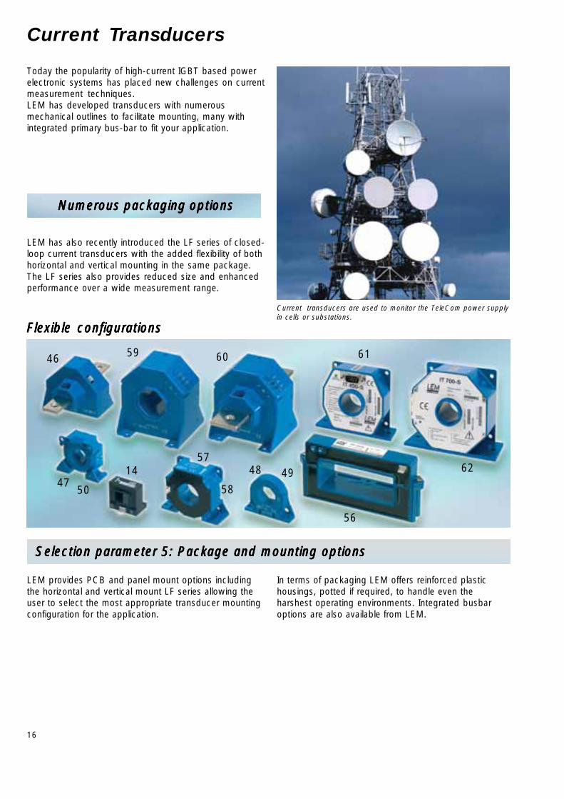
Today the popularity of high-current IGBT based powerelectronic systems has placed new challenges on currentmeasurement techniques.LEM has developed transducers with numerousmechanical outlines to facilitate mounting, many withintegrated primary bus-bar to fit your application.
Numerous packaging optionsNumerous packaging optionsNumerous packaging optionsNumerous packaging optionsNumerous packaging options
LEM has also recently introduced the LF series of closed-loop current transducers with the added flexibility of bothhorizontal and vertical mounting in the same package.The LF series also provides reduced size and enhancedperformance over a wide measurement range.
Selection parameter 5: Package and mounting options Selection parameter 5: Package and mounting options Selection parameter 5: Package and mounting options Selection parameter 5: Package and mounting options Selection parameter 5: Package and mounting options
LEM provides PCB and panel mount options includingthe horizontal and vertical mount LF series allowing theuser to select the most appropriate transducer mountingconfiguration for the application.
In terms of packaging LEM offers reinforced plastichousings, potted if required, to handle even theharshest operating environments. Integrated busbaroptions are also available from LEM.
Current transducers are used to monitor the TeleCom power supplyin cells or substations.
Flexible configurationsFlexible configurationsFlexible configurationsFlexible configurationsFlexible configurations

17
IIIIIPNPNPNPNPN = 400 A ... 800 A = 400 A ... 800 A = 400 A ... 800 A = 400 A ... 800 A = 400 A ... 800 A
IPN IP VC VOUT f X TA Connection TypeIOUT @ IPN Primary Sec.
TA =@ IPN 25°C
A A V kHz % °C No.
400 ±600 O/L ±12...15 4 V DC-50 (-3dB)① 2.7 -20...+80 ●●●●● ●●●●● 17 HTB 400-PHTB 400-PHTB 400-PHTB 400-PHTB 400-P
400 ±900 O/L ±15 4 V DC-50 (-3dB)① 2.7 -10...+80 ●●●●● ●●●●● 29 HAC 400-SHAC 400-SHAC 400-SHAC 400-SHAC 400-S
400 ±900 O/L ±15 4 V DC-50 (-3dB)① 3 -10...+80 ●●●●● ●●●●● 15 HAS 400-SHAS 400-SHAS 400-SHAS 400-SHAS 400-S
400 ±1000 O/L ±15 4 V DC-50 (-3dB)① 1.75 -25...+85 ●●●●● ●●●●● 14 HAL 400-SHAL 400-SHAL 400-SHAL 400-SHAL 400-S
400 ±1000 O/L ±15 4 V DC-50 (-3dB)① 1.75 -25...+85 ●●●●● ●●●●● 30 HTA 400-SHTA 400-SHTA 400-SHTA 400-SHTA 400-S
400 ±600 O/L +5/0 2.5V or VRef ±0.625V DC-50 (-3dB)① 2.3 -40...+85 ●●●●● ●●●●● 12 HAIS 400-PHAIS 400-PHAIS 400-PHAIS 400-PHAIS 400-P ②
400 ±600 O/L ±12…15 4 V DC-8 (-1dB)① 3.75 -10...+70 ●●●●● ●●●●● 31 HOP 400-SBHOP 400-SBHOP 400-SBHOP 400-SBHOP 400-SB
400 ±800 O/L ±12…15 4 V DC-10 (-1dB)① 3.4 -10...+70 ●●●●● ●●●●● 11 HTR 400-SBHTR 400-SBHTR 400-SBHTR 400-SBHTR 400-SB
400 ±600 O/L +12…15 VC/2 V ±1.667 V DC-50 (-3dB)① 1.5 -25...+85 ●●●●● ●●●●● 19 HTB 400-P/SP5HTB 400-P/SP5HTB 400-P/SP5HTB 400-P/SP5HTB 400-P/SP5
400 ±900 O/L +5/0 VC/2 V ± 0.5 V DC-50 (-3dB)① 4 -10...+80 ●●●●● ●●●●● 16 HAS 400-S/SP1HAS 400-S/SP1HAS 400-S/SP1HAS 400-S/SP1HAS 400-S/SP1
500 ±900 O/L ±15 4 V DC-50 (-3dB)① 3 -10...+80 ●●●●● ●●●●● 15 HAS 500-SHAS 500-SHAS 500-SHAS 500-SHAS 500-S
500 ±1000 O/L ±15 4 V DC-50 (-3dB)① 1.75 -25...+85 ●●●●● ●●●●● 14 HAL 500-SHAL 500-SHAL 500-SHAL 500-SHAL 500-S
500 ±1000 O/L ±15 4 V DC-50 (-3dB)① 1.75 -25...+85 ●●●●● ●●●●● 30 HTA 500-SHTA 500-SHTA 500-SHTA 500-SHTA 500-S
500 ±1500 O/L ±15 4 V DC-50 (-3dB)① 2.75 -10...+80 ●●●●● ●●●●● 54 HAT 500-SHAT 500-SHAT 500-SHAT 500-SHAT 500-S
500 ±1500 O/L ±15 4 V DC-25 (-3dB)① 3.25 -10...+80 ●●●●● ●●●●● 55 HAX 500-SHAX 500-SHAX 500-SHAX 500-SHAX 500-S
500 ±750 O/L ±12…15 4 V DC-8 (-1dB)① 3.75 -10...+70 ●●●●● ●●●●● 31 HOP 500-SBHOP 500-SBHOP 500-SBHOP 500-SBHOP 500-SB
500 ±1000 O/L ±12…15 4 V DC-10 (-1dB)① 3 -10...+70 ●●●●● ●●●●● 56 HOP 500-SB/SP1HOP 500-SB/SP1HOP 500-SB/SP1HOP 500-SB/SP1HOP 500-SB/SP1
500 ±1000 O/L ±12…15 4 V DC-10 (-1dB)① 3.4 -10...+70 ●●●●● ●●●●● 11 HTR 500-SBHTR 500-SBHTR 500-SBHTR 500-SBHTR 500-SB
500 ±900 O/L +5/0 VC/2 V ± 0.5 V DC-50 (-3dB)① 4 -10...+80 ●●●●● ●●●●● 16 HAS 500-S/SP1HAS 500-S/SP1HAS 500-S/SP1HAS 500-S/SP1HAS 500-S/SP1
600 ±900 O/L ±15 4 V DC-50 (-3dB)① 3 -10...+80 ●●●●● ●●●●● 15 HAS 600-SHAS 600-SHAS 600-SHAS 600-SHAS 600-S
600 ±1000 O/L ±15 4 V DC-50 (-3dB)① 1.75 -25...+85 ●●●●● ●●●●● 14 HAL 600-SHAL 600-SHAL 600-SHAL 600-SHAL 600-S
600 ±1000 O/L ±15 4 V DC-50 (-3dB)① 1.75 -25...+85 ●●●●● ●●●●● 30 HTA 600-SHTA 600-SHTA 600-SHTA 600-SHTA 600-S
600 ±1800 O/L ±15 4 V DC-50 (-3dB)① 2.7 -10...+80 ●●●●● ●●●●● 29 HAC 600-SHAC 600-SHAC 600-SHAC 600-SHAC 600-S
600 ±900 O/L ±12…15 4 V DC-8 (-1dB)① 3.75 -10...+70 ●●●●● ●●●●● 31 HOP 600-SBHOP 600-SBHOP 600-SBHOP 600-SBHOP 600-SB
600 ±900 O/L +5/0 VC/2 V ± 0.5 V DC-50 (-3dB)① 4 -10...+80 ●●●●● ●●●●● 16 HAS 600-S/SP1HAS 600-S/SP1HAS 600-S/SP1HAS 600-S/SP1HAS 600-S/SP1
800 ±1800 O/L ±15 4 V DC-50 (-3dB)① 2.7 -10...+80 ●●●●● ●●●●● 29 HAC 800-SHAC 800-SHAC 800-SHAC 800-SHAC 800-S
800 ±2400 O/L ±15 4 V DC-50 (-3dB)① 2.75 -10...+80 ●●●●● ●●●●● 54 HAT 800-SHAT 800-SHAT 800-SHAT 800-SHAT 800-S
800 ±1600 O/L ±12…15 4 V DC-10 (-1dB)① 3 -10...+70 ●●●●● ●●●●● 56 HOP 800-SBHOP 800-SBHOP 800-SBHOP 800-SBHOP 800-SB
500 ±800 C/L ±12...15 250 mA DC-100 (-3dB) 0.24 -10...+85 ●●●●● ●●●●● 44 LA 305-S/SP1LA 305-S/SP1LA 305-S/SP1LA 305-S/SP1LA 305-S/SP1
500 ±800 C/L ±12...15 250 mA DC-100 (-3dB) 0.24 -10...+85 ●●●●● ●●●●● 46 LA 305-T/SP1LA 305-T/SP1LA 305-T/SP1LA 305-T/SP1LA 305-T/SP1
500 ±800 C/L ±15…24 100 mA DC-100 (-1dB) 0.3 -40...+70 ●●●●● ●●●●● 57 LF 505-SLF 505-SLF 505-SLF 505-SLF 505-S
500 ± 800 C/L ±15…24 100 mA DC-100 (-1dB) 0,3 -10...+70 ●●●●● ●●●●● 58 LF 505-S/SP15LF 505-S/SP15LF 505-S/SP15LF 505-S/SP15LF 505-S/SP15
500 ±1200 C/L ±15…24 100 mA DC-150 (-1dB) 0.4 -10...+85 ●●●●● ●●●●● 59 LT 505-SLT 505-SLT 505-SLT 505-SLT 505-S
500 ±1200 C/L ±15…24 100 mA DC-150 (-1dB) 0.4 -10...+85 ●●●●● ●●●●● 60 LT 505-TLT 505-TLT 505-TLT 505-TLT 505-T
400 ±400 "IT“ ±15 200 mA DC-100 (-3dB) 0.0033 +10...+50 ●●●●● ●●●●● 61 IT 400-SIT 400-SIT 400-SIT 400-SIT 400-S
600 ±600 "IT“ ±15 400 mA DC-100 (3dB) 0.0013 +10...+50 ●●●●● ●●●●● 52 IT 600-SIT 600-SIT 600-SIT 600-SIT 600-S
700 ±700 "IT“ ±15 400 mA DC-500 (3dB) 0.0053 +10...+50 ●●●●● ●●●●● 62 IT 700-SIT 700-SIT 700-SIT 700-SIT 700-S
Pac
kagi
ngP
acka
ging
Pac
kagi
ngP
acka
ging
Pac
kagi
ng
PC
BP
CB
PC
BP
CB
PC
B
Ape
rture
, bus
-ba
r, oth
er
PC
BP
CB
PC
BP
CB
PC
B
Oth
erO
ther
Oth
erO
ther
Oth
er
Tec
hno
log
yT
echn
olo
gy
Tec
hno
log
yT
echn
olo
gy
Tec
hno
log
y
Datasheets: wwwDatasheets: wwwDatasheets: wwwDatasheets: wwwDatasheets: www.lem.com.lem.com.lem.com.lem.com.lem.com
① Small signal bandwidth to avoid excessive core heating at high frequency.② Refout & Refin modes.
recognizedon the way to be recognized
Open-loop "IT"-typesClosed-loop

18
68
69
54 55 63
6465
66
70
7371
7467
72 75
Current Transducers
Leveraging over 30 years experience designing currentand voltage transducers for industries most demandingapplications, LEM continues to meet the challengesimposed by today’s applications, by compact size,reduced weight, higher EMC immunity, and safetyisolation with enhanced measurement accuracy,increased reliability and the same high level ofperformance our customers expect.
LEM Know HowLEM Know HowLEM Know HowLEM Know HowLEM Know How...............
Our engineers are available to assist at any point in thedevelopment process to ensure the selected transduceris the most appropriate for the application. LEM offers ourknowledge and experience to provide applicationassistance to help maximize the performance of ourproduct in your design. In addition to modern tools likefinite element analysis, LEM also has test facilities, andbench level systems, to allow us to recreate youroperating conditions in our labs. We do this to help youto optimize your design and guarantee its finalperformance.
Forklift truck drive control system ensured by current measurements
ModularityModularityModularityModularityModularity
Selection parameter 6: Secondary connections Selection parameter 6: Secondary connections Selection parameter 6: Secondary connections Selection parameter 6: Secondary connections Selection parameter 6: Secondary connections
With PCB mount packages, secondary connection isachieved with standard solderable pin terminals.
For Panel mount transducers LEM offers the followingstandard secondary connection types:
• Metric (M4, M5) and UNC threaded studs• Fast-on• Cable• Molex
LEM also offers custom and specialty connections, i.e.LEMO, Sub-D, etc, as well as AMP, Burndy, and otherindustry standard connectors.

19
IIIIIPNPNPNPNPN = 1000 A ... 10 = 1000 A ... 10 = 1000 A ... 10 = 1000 A ... 10 = 1000 A ... 10 000 A000 A000 A000 A000 A
IPN IP VC VOUT f X TA Connection TypeIOUT @ IPN Primary Sec.
TA =@ IPN 25°C
A A V kHz % °C No.
1000 ±1000 O/L ±15 4 V DC-50 (-3dB)① 1.75 -25...+85 ●●●●● ●●●●● 30 HTA 1000-SHTA 1000-SHTA 1000-SHTA 1000-SHTA 1000-S
1000 ±3000 O/L ±15 4 V DC-50 (-3dB)① 2.75 -10...+80 ●●●●● ●●●●● 54 HAT 1000-SHAT 1000-SHAT 1000-SHAT 1000-SHAT 1000-S
1000 ±3000 O/L ±15 4 V DC-25 (-3dB)① 3.25 -10...+80 ●●●●● ●●●●● 55 HAX 1000-SHAX 1000-SHAX 1000-SHAX 1000-SHAX 1000-S
1000 ±2000 O/L ±12…15 4 V DC-10 (-1dB)① 3 -10...+70 ●●●●● ●●●●● 56 HOP 1000-SBHOP 1000-SBHOP 1000-SBHOP 1000-SBHOP 1000-SB
1200 ±3000 O/L ±15 4 V DC-50 (-3dB)① 2.75 -10...+80 ●●●●● ●●●●● 54 HAT 1200-SHAT 1200-SHAT 1200-SHAT 1200-SHAT 1200-S
1500 ±3000 O/L ±15 4 V DC-50 (-3dB)① 2.75 -10...+80 ●●●●● ●●●●● 54 HAT 1500-SHAT 1500-SHAT 1500-SHAT 1500-SHAT 1500-S
1500 ±4500 O/L ±15 4 V DC-25 (-3dB)① 3.25 -10...+80 ●●●●● ●●●●● 55 HAX 1500-SHAX 1500-SHAX 1500-SHAX 1500-SHAX 1500-S
1500 ±3000 O/L ±12…15 4 V DC-10 (-1dB)① 3 -10...+70 ●●●●● ●●●●● 56 HOP 1500-SBHOP 1500-SBHOP 1500-SBHOP 1500-SBHOP 1500-SB
2000 ±5500 O/L ±15 4 V DC-25 (-3dB)① 3.25 -10...+80 ●●●●● ●●●●● 55 HAX 2000-SHAX 2000-SHAX 2000-SHAX 2000-SHAX 2000-S
2000 ±3000 O/L ±12…15 4 V DC-10 (-1dB)① 3 -10...+70 ●●●●● ●●●●● 56 HOP 2000-SBHOP 2000-SBHOP 2000-SBHOP 2000-SBHOP 2000-SB
2000 ±3000 O/L ±12…15 4 V DC-4 (-1dB)① 3 -10...+70 ●●●●● ●●●●● 63 HOP 2000-SB/SP1HOP 2000-SB/SP1HOP 2000-SB/SP1HOP 2000-SB/SP1HOP 2000-SB/SP1
2500 ±5500 O/L ±15 4 V DC-25 (-3dB)① 3.25 -10...+80 ●●●●● ●●●●● 55 HAX 2500-SHAX 2500-SHAX 2500-SHAX 2500-SHAX 2500-S
1000 ±1500 C/L ±15...24 200 mA DC-150 (-1dB) 0.3 -10...+85 ●●●●● ●●●●● 64 LF 1005-SLF 1005-SLF 1005-SLF 1005-SLF 1005-S
1000 ±2000 C/L ±15...24 200 mA DC-150 (-1dB) 0.3 -10...+85 ●●●●● ●●●●● 59 LT 1005-SLT 1005-SLT 1005-SLT 1005-SLT 1005-S
1000 ±2000 C/L ±15...24 200 mA DC-150 (-1dB) 0.3 -10...+85 ●●●●● ●●●●● 60 LT 1005-TLT 1005-TLT 1005-TLT 1005-TLT 1005-T
1000 ±1500 C/L ±15…24 200 mA DC-150 (-1dB) 0,3 -10...+85 ●●●●● ●●●●● 65 LF 1005-S/SP22LF 1005-S/SP22LF 1005-S/SP22LF 1005-S/SP22LF 1005-S/SP22
2000 ±3000 C/L ±15...24 400 mA DC-100 (-1dB) 0.2 0...+70 ●●●●● ●●●●● 66 LT 2000-SLT 2000-SLT 2000-SLT 2000-SLT 2000-S
2000 ±3000 C/L ±15...24 400 mA DC-100 (-1dB) 0.2 0...+70 ●●●●● ●●●●● 67 LT 2000-TLT 2000-TLT 2000-TLT 2000-TLT 2000-T
2000 ±3000 C/L ±15...24 400 mA DC-100 (-1dB) 0.2 0...+70 ●●●●● ●●●●● 68 LT 2005-SLT 2005-SLT 2005-SLT 2005-SLT 2005-S
2000 ±3000 C/L ±15...24 400 mA DC-100 (-1dB) 0.2 0...+70 ●●●●● ●●●●● 69 LT 2005-TLT 2005-TLT 2005-TLT 2005-TLT 2005-T
2000 ±3000 C/L ±15...24 400 mA DC-100 (-1dB) 0.2 -25...+70 ●●●●● ●●●●● 70 LF 2000-SLF 2000-SLF 2000-SLF 2000-SLF 2000-S
2000 ±3000 C/L ±15...24 400 mA DC-100 (-1dB) 0.2 -25...+70 ●●●●● ●●●●● 71 LF 2005-SLF 2005-SLF 2005-SLF 2005-SLF 2005-S
4000 ±4000 O/L ±15 10 V DC-3 (-3dB)① 2 -25…+80 ●●●●● ●●●●● 72 HAZ 4000-SBHAZ 4000-SBHAZ 4000-SBHAZ 4000-SBHAZ 4000-SB
4000 ±6000 C/L ±24 800 mA DC-100 (-1dB) 0.2 -25...+70 ●●●●● ●●●●● 73 LT 4000-SLT 4000-SLT 4000-SLT 4000-SLT 4000-S
4000 ±6000 C/L ±24 800 mA DC-100 (-1dB) 0.2 -25...+70 ●●●●● ●●●●● 74 LT 4000-TLT 4000-TLT 4000-TLT 4000-TLT 4000-T
6000 ±6000 O/L ±15 10 V DC-3 (-3dB)① 2 -25…+80 ●●●●● ●●●●● 72 HAZ 6000-SBHAZ 6000-SBHAZ 6000-SBHAZ 6000-SBHAZ 6000-SB
10000 ±10000 O/L ±15 10 V DC-3 (-3dB)① 2 -25…+80 ●●●●● ●●●●● 72 HAZ 10000-SBHAZ 10000-SBHAZ 10000-SBHAZ 10000-SBHAZ 10000-SB
10000 ±15000 C/L ±48...60 1 A DC-100 (-1dB) 0.3 -25...+70 ●●●●● ●●●●● 75 LT 10000-SLT 10000-SLT 10000-SLT 10000-SLT 10000-S
12000 ±12000 O/L ±15 10 V DC-3 (-3dB)① 2 -25…+80 ●●●●● ●●●●● 72 HAZ 12000-SBHAZ 12000-SBHAZ 12000-SBHAZ 12000-SBHAZ 12000-SB
14000 ±14000 O/L ±15 10 V DC-3 (-3dB)① 2 -25…+80 ●●●●● ●●●●● 72 HAZ 14000-SBHAZ 14000-SBHAZ 14000-SBHAZ 14000-SBHAZ 14000-SB
20000 ±20000 O/L ±15 10 V DC-3 (-3dB)① 2 -25…+80 ●●●●● ●●●●● 72 HAZ 20000-SBHAZ 20000-SBHAZ 20000-SBHAZ 20000-SBHAZ 20000-SB
Tec
hno
log
yT
echn
olo
gy
Tec
hno
log
yT
echn
olo
gy
Tec
hno
log
y
Datasheets: wwwDatasheets: wwwDatasheets: wwwDatasheets: wwwDatasheets: www.lem.com.lem.com.lem.com.lem.com.lem.com
① Small signal bandwidth to avoid excessive core heating at high frequency.recognizedon the way to be recognized
Open-loop Closed-loop
Pac
kagi
ngP
acka
ging
Pac
kagi
ngP
acka
ging
Pac
kagi
ng
PC
BP
CB
PC
BP
CB
PC
B
Ape
rture
, bus
-ba
r, oth
er
PC
BP
CB
PC
BP
CB
PC
B
Oth
erO
ther
Oth
erO
ther
Oth
er
20
78
80
79
8176
77
Current Transducers for Automation
Selection parameter 7: Output signal Selection parameter 7: Output signal Selection parameter 7: Output signal Selection parameter 7: Output signal Selection parameter 7: Output signal
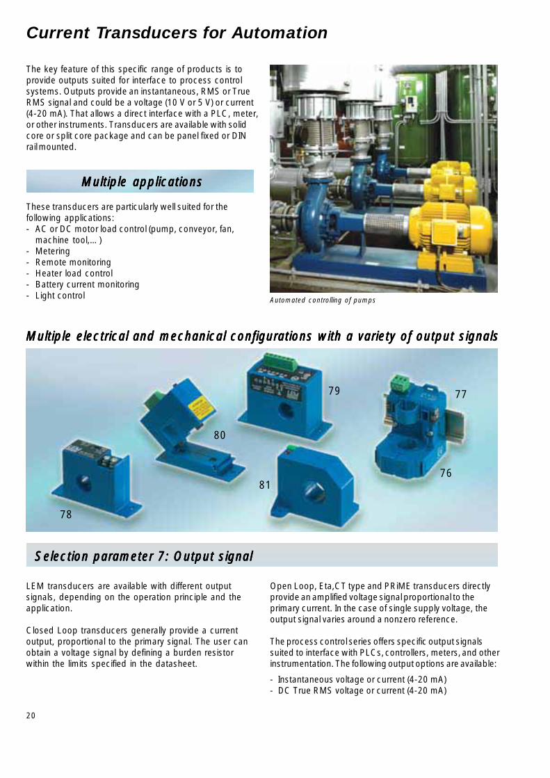
The key feature of this specific range of products is toprovide outputs suited for interface to process controlsystems. Outputs provide an instantaneous, RMS or TrueRMS signal and could be a voltage (10 V or 5 V) or current(4-20 mA). That allows a direct interface with a PLC, meter,or other instruments. Transducers are available with solidcore or split core package and can be panel fixed or DINrail mounted.
Multiple applicationsMultiple applicationsMultiple applicationsMultiple applicationsMultiple applications
These transducers are particularly well suited for thefollowing applications:- AC or DC motor load control (pump, conveyor, fan,
machine tool,…)- Metering- Remote monitoring- Heater load control- Battery current monitoring- Light control Automated controlling of pumps
LEM transducers are available with different outputsignals, depending on the operation principle and theapplication.
Closed Loop transducers generally provide a currentoutput, proportional to the primary signal. The user canobtain a voltage signal by defining a burden resistorwithin the limits specified in the datasheet.
Open Loop, Eta,CT type and PRiME transducers directlyprovide an amplified voltage signal proportional to theprimary current. In the case of single supply voltage, theoutput signal varies around a nonzero reference.
The process control series offers specific output signalssuited to interface with PLCs, controllers, meters, and otherinstrumentation. The following output options are available:
- Instantaneous voltage or current (4-20 mA)- DC True RMS voltage or current (4-20 mA)
Multiple electrical and mechanical configurations with a variety of output signalsMultiple electrical and mechanical configurations with a variety of output signalsMultiple electrical and mechanical configurations with a variety of output signalsMultiple electrical and mechanical configurations with a variety of output signalsMultiple electrical and mechanical configurations with a variety of output signals
21
②
②
②
②
②
②
②
②
②
②
②
②
②
②
②
②
②
②
②
②
②
②
②
②
②
②
②
②
②
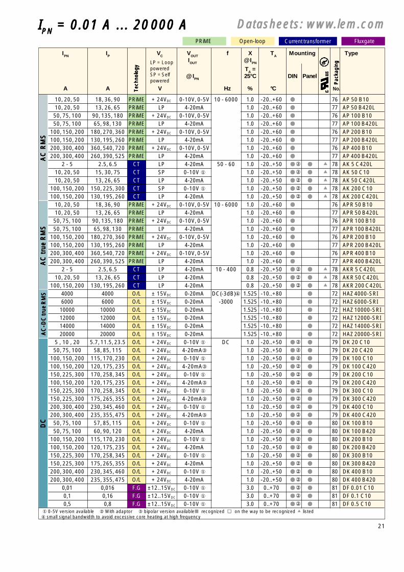
Fluxgate
IPN IP VC VOUT f X TA Mounting TypeIOUT @ IPN
TA =@ IPN 25°C DIN Panel
A A V Hz % °C No.
10, 20, 50 18, 36, 90 PRiME + 24VDC 0-10V, 0-5V 10 - 6000 1.0 -20..+60 ●●●●● 76 AP 50 B1010, 20, 50 13, 26, 65 PRiME LP 4-20mA 10 - 6000 1.0 -20..+60 ●●●●● 77 AP 50 B420L50, 75, 100 90, 135, 180 PRiME + 24VDC 0-10V, 0-5V 10 - 6000 1.0 -20..+60 ●●●●● 76 AP 100 B1050, 75, 100 65, 98, 130 PRiME LP 4-20mA 10 - 6000 1.0 -20..+60 ●●●●● 77 AP 100 B420L
100, 150, 200 180, 270, 360 PRiME + 24VDC 0-10V, 0-5V 10 - 6000 1.0 -20..+60 ●●●●● 76 AP 200 B10100, 150, 200 130, 195, 260 PRiME LP 4-20mA 10 - 6000 1.0 -20..+60 ●●●●● 77 AP 200 B420L200, 300, 400 360, 540, 720 PRiME + 24VDC 0-10V, 0-5V 10 - 6000 1.0 -20..+60 ●●●●● 76 AP 400 B10200, 300, 400 260, 390, 525 PRiME LP 4-20mA 10 - 6000 1.0 -20..+60 ●●●●● 77 AP 400 B420L
2 - 5 2.5, 6.5 CT LP 4-20mA 50 - 60 1.0 -20..+50 ●●●●● ●●●●● 78 AK 5 C420L10, 20, 50 15, 30, 75 CT SP 0-10V ① 50 - 60 1.0 -20..+50 ●●●●● ●●●●● 78 AK 50 C1010, 20, 50 13, 26, 65 CT LP 4-20mA 50 - 60 1.0 -20..+50 ●●●●● ●●●●● 78 AK 50 C420L
100, 150, 200 150, 225, 300 CT SP 0-10V ① 50 - 60 1.0 -20..+50 ●●●●● ●●●●● 78 AK 200 C10100, 150, 200 130, 195, 260 CT LP 4-20mA 50 - 60 1.0 -20..+50 ●●●●● ●●●●● 78 AK 200 C420L
10, 20, 50 18, 36, 90 PRiME + 24VDC 0-10V, 0-5V 10 - 6000 1.0 -20..+60 ●●●●● 76 APR 50 B1010, 20, 50 13, 26, 65 PRiME LP 4-20mA 10 - 6000 1.0 -20..+60 ●●●●● 77 APR 50 B420L50, 75, 100 90, 135, 180 PRiME + 24VDC 0-10V, 0-5V 10 - 6000 1.0 -20..+60 ●●●●● 76 APR 100 B1050, 75, 100 65, 98, 130 PRiME LP 4-20mA 10 - 6000 1.0 -20..+60 ●●●●● 77 APR 100 B420L
100, 150, 200 180, 270, 360 PRiME + 24VDC 0-10V, 0-5V 10 - 6000 1.0 -20..+60 ●●●●● 76 APR 200 B10100, 150, 200 130, 195, 260 PRiME LP 4-20mA 10 - 6000 1.0 -20..+60 ●●●●● 77 APR 200 B420L200, 300, 400 360, 540, 720 PRiME + 24VDC 0-10V, 0-5V 10 - 6000 1.0 -20..+60 ●●●●● 76 APR 400 B10200, 300, 400 260, 390, 525 PRiME LP 4-20mA 10 - 6000 1.0 -20..+60 ●●●●● 77 APR 400 B420L
2 - 5 2.5, 6.5 CT LP 4-20mA 10 - 400 0.8 -20..+50 ●●●●● ●●●●● 78 AKR 5 C420L10, 20, 50 13, 26, 65 CT LP 4-20mA 10 - 400 0.8 -20..+50 ●●●●● ●●●●● 78 AKR 50 C420L
100, 150, 200 130, 195, 260 CT LP 4-20mA 10 - 400 0.8 -20..+50 ●●●●● ●●●●● 78 AKR 200 C420L4000 4000 O/L ± 15VDC 0-20mA DC(-3dB)④ 1.525 -10..+80 ●●●●● 72 HAZ 4000-SRI6000 6000 O/L ± 15VDC 0-20mA -3000 1.525 -10..+80 ●●●●● 72 HAZ 6000-SRI10000 10000 O/L ± 15VDC 0-20mA DC(-3dB)④ 1.525 -10..+80 ●●●●● 72 HAZ 10000-SRI12000 12000 O/L ± 15VDC 0-20mA DC(-3dB)④ 1.525 -10..+80 ●●●●● 72 HAZ 12000-SRI14000 14000 O/L ± 15VDC 0-20mA DC(-3dB)④ 1.525 -10..+80 ●●●●● 72 HAZ 14000-SRI20000 20000 O/L ± 15VDC 0-20mA DC(-3dB)④ 1.525 -10..+80 ●●●●● 72 HAZ 20000-SRI
5 , 10 , 20 5.7, 11.5, 23.5 O/L + 24VDC 0-10V ① DC 1.0 -20..+50 ●●●●● ●●●●● 79 DK 20 C1050, 75, 100 58, 85, 115 O/L + 24VDC 4-20mA③ DC 1.0 -20..+50 ●●●●● ●●●●● 79 DK 20 C420
100, 150, 200 115, 170, 230 O/L + 24VDC 0-10V ① DC 1.0 -20..+50 ●●●●● ●●●●● 79 DK 100 C10100, 150, 200 120, 175, 235 O/L + 24VDC 4-20mA③ DC 1.0 -20..+50 ●●●●● ●●●●● 79 DK 100 C420150, 225, 300 170, 258, 345 O/L + 24VDC 0-10V ① DC 1.0 -20..+50 ●●●●● ●●●●● 79 DK 200 C10100, 150, 200 120, 175, 235 O/L + 24VDC 4-20mA③ DC 1.0 -20..+50 ●●●●● ●●●●● 79 DK 200 C420150, 225, 300 170, 258, 345 O/L + 24VDC 0-10V ① DC 1.0 -20..+50 ●●●●● ●●●●● 79 DK 300 C10150, 225, 300 175, 265, 355 O/L + 24VDC 4-20mA③ DC 1.0 -20..+50 ●●●●● ●●●●● 79 DK 300 C420200, 300, 400 230, 345, 460 O/L + 24VDC 0-10V ① DC 1.0 -20..+50 ●●●●● ●●●●● 79 DK 400 C10200, 300, 400 235, 355, 475 O/L + 24VDC 4-20mA③ DC 1.0 -20..+50 ●●●●● ●●●●● 79 DK 400 C42050, 75, 100 57, 85, 115 O/L + 24VDC 0-10V ① DC 1.0 -20..+50 ●●●●● ●●●●● 80 DK 100 B1050, 75, 100 60, 90, 120 O/L + 24VDC 4-20mA DC 1.0 -20..+50 ●●●●● ●●●●● 80 DK 100 B420
100, 150, 200 115, 170, 230 O/L + 24VDC 0-10V ① DC 1.0 -20..+50 ●●●●● ●●●●● 80 DK 200 B10100, 150, 200 120, 175, 235 O/L + 24VDC 4-20mA DC 1.0 -20..+50 ●●●●● ●●●●● 80 DK 200 B420150, 225, 300 170, 258, 345 O/L + 24VDC 0-10V ① DC 1.0 -20..+50 ●●●●● ●●●●● 80 DK 300 B10150, 225, 300 175, 265, 355 O/L + 24VDC 4-20mA DC 1.0 -20..+50 ●●●●● ●●●●● 80 DK 300 B420200, 300, 400 230, 345, 460 O/L + 24VDC 0-10V ① DC 1.0 -20..+50 ●●●●● ●●●●● 80 DK 400 B10200, 300, 400 235, 355, 475 O/L + 24VDC 4-20mA DC 1.0 -20..+50 ●●●●● ●●●●● 80 DK 400 B420
0,01 0,016 F.G ±12..15VDC 0-10V ① DC 3.0 0..+70 ●●●●● ●●●●● 81 DF 0.01 C100,1 0,16 F.G ±12..15VDC 0-10V ① DC 3.0 0..+70 ●●●●● ●●●●● 81 DF 0.1 C100,5 0,8 F.G ±12..15VDC 0-10V ① DC 3.0 0..+70 ●●●●● ●●●●● 81 DF 0.5 C10
① 0-5V version available ② With adaptor ③ bipolar version available recognized on the way to be recognized listed ④ small signal bandwidth to avoid excessive core heating at high frequency
Pac
kagi
ngP
acka
ging
Pac
kagi
ngP
acka
ging
Pac
kagi
ng
Tec
hno
log
yT
echn
olo
gy
Tec
hno
log
yT
echn
olo
gy
Tec
hno
log
y
IIIIIPNPNPNPNPN = 0.01 A ... 20 = 0.01 A ... 20 = 0.01 A ... 20 = 0.01 A ... 20 = 0.01 A ... 20 000 A000 A000 A000 A000 A Datasheets: wwwDatasheets: wwwDatasheets: wwwDatasheets: wwwDatasheets: www.lem.com.lem.com.lem.com.lem.com.lem.com
LP = LooppoweredSP = Selfpowered
AC
RM
SA
C R
MS
AC
RM
SA
C R
MS
AC
RM
SA
C tr
ue R
MS
AC
true
RM
SA
C tr
ue R
MS
AC
true
RM
SA
C tr
ue R
MS
DC
DC
DC
DC
DC
Current transformer Open-loopPRiMEA
C-D
C tr
ue R
MS
AC
-DC
true
RM
SA
C-D
C tr
ue R
MS
AC
-DC
true
RM
SA
C-D
C tr
ue R
MS
22
8483
85
87
82
Voltage Transducers
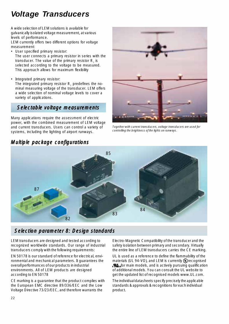
Selection parameter 8: Design standards Selection parameter 8: Design standards Selection parameter 8: Design standards Selection parameter 8: Design standards Selection parameter 8: Design standards
A wide selection of LEM solutions is available forgalvanically isolated voltage measurement, at variouslevels of performance.LEM currently offers two different options for voltagemeasurement:• User specified primary resistor:
The user connects a primary resistor in series with thetransducer. The value of the primary resistor R1 isselected according to the voltage to be measured.This approach allows for maximum flexibility
• Integrated primary resistor:The integrated primary resistor R1 predefines the no-minal measuring voltage of the transducer. LEM offersa wide selection of nominal voltage levels to cover avariety of applications.
Selectable voltage measurementsSelectable voltage measurementsSelectable voltage measurementsSelectable voltage measurementsSelectable voltage measurements
Many applications require the assessment of electricpower, with the combined measurement of LEM voltageand current transducers. Users can control a variety ofsystems, including the lighting of airport runways.
Together with current transducers, voltage transducers are used forcontrolling the brightness of the lights on runways.
Multiple package configurationsMultiple package configurationsMultiple package configurationsMultiple package configurationsMultiple package configurations
LEM transducers are designed and tested according torecognized worldwide standards. Our range of industrialtransducers comply with the following requirements:
EN 50178 is our standard of reference for electrical, envi-ronmental and mechanical parameters. It guarantees theoverall performances of our products in industrialenvironments. All of LEM products are designedaccording to EN 50178
CE marking is a guarantee that the product complies withthe European EMC directive 89/336/EEC and the LowVoltage Directive 73/23/EEC, and therefore warrants the
Electro-Magnetic Compatibility of the transducer and thesafety isolation between primary and secondary. Virtuallythe entire line of LEM transducers carries the CE marking.
UL is used as a reference to define the flammability of thematerials (UL 94-VO), and LEM is currently recognised for main models, and is actively pursuing qualificationof additional models. You can consult the UL website toget the updated list of recognised models www.UL.com.
The individual datasheets specify precisely the applicablestandards & approvals & recognitions for each individualproduct.

23
IIIIIPNPNPNPNPN IIIII PPPPP Techno-Techno-Techno-Techno-Techno- VVVVVCCCCC IIIIIOUTOUTOUTOUTOUT fffff XXXXXGGGGG TTTTTAAAAA TypeTypeTypeTypeType(V(V(V(V(VPNPNPNPNPN))))) (V(V(V(V(VPPPPP))))) logylogylogylogylogy TTTTTA A A A A = 25°C= 25°C= 25°C= 25°C= 25°C
@ I@ I@ I@ I@ IPNPNPNPNPN % @ I% @ I% @ I% @ I% @ IPNPNPNPNPN with max with max with max with max with max
mAmAmAmAmA mAmAmAmAmA VVVVV mAmAmAmAmA kHzkHzkHzkHzkHz offset takenoffset takenoffset takenoffset takenoffset taken °C°C°C°C°C No.No.No.No.No.
10 ±14(10 to 500 V) (700 V) C/L ±12...15 25 ① 1 0...+70 82 LV 25-P LV 25-P LV 25-P LV 25-P LV 25-P ②
10 ±20(100 to 2500 V) (5000 V) C/L ±15 50 ① 0.7 0...+70 83 LV 100 LV 100 LV 100 LV 100 LV 100 ③
20 ±40(100 to 2500 V) (5000 V) C/L ±15...24 100 ① 0.6 -25...+70 84 LV 200-AW/2 LV 200-AW/2 LV 200-AW/2 LV 200-AW/2 LV 200-AW/2 ③
① See response time in the individual data sheet.② The primary and secondary connections of this transducer are done on PCB.③ Mechanical mounting.
recognizedon the way to be recognized
VVVVVPNPNPNPNPN = 10 V ... 2500 V = 10 V ... 2500 V = 10 V ... 2500 V = 10 V ... 2500 V = 10 V ... 2500 VVoltage transducers (without resistor R1)
VVVVVPNPNPNPNPN = 50 V ... 400 V = 50 V ... 400 V = 50 V ... 400 V = 50 V ... 400 V = 50 V ... 400 VVoltage transducers (with built in resistor R1, mechnical mounting)
±V±V±V±V±VPNPNPNPNPN ±V±V±V±V±V
PPPPP Techno-Techno-Techno-Techno-Techno- VVVVVCCCCC VVVVVOUTOUTOUTOUTOUT fffff XXXXXGGGGG TTTTTAAAAA TypeTypeTypeTypeTypelogylogylogylogylogy IIIIIOUTOUTOUTOUTOUT TTTTTA A A A A = 25°C= 25°C= 25°C= 25°C= 25°C
@ V@ V@ V@ V@ VPNPNPNPNPN @ V@ V@ V@ V@ V
PNPNPNPNPN with max with max with max with max with max
VVVVV VVVVV VVVVV kHzkHzkHzkHzkHz offset taken %offset taken %offset taken %offset taken %offset taken % °C°C°C°C°C No.No.No.No.No.
50 75 Isolation ±12...24 50 mA DC-13 (-3dB) 0.7 -40...+85 85 AV 100-50AV 100-50AV 100-50AV 100-50AV 100-50Amplifier
125 187.5 Isolation ±12...24 50 mA DC-13 (-3dB) 0.7 -40...+85 85 AV 100-125AV 100-125AV 100-125AV 100-125AV 100-125Amplifier
150 225 Isolation ±12...24 50 mA DC-13 (-3dB) 0.7 -40...+85 85 AV 100-150AV 100-150AV 100-150AV 100-150AV 100-150Amplifier
250 375 Isolation ±12...24 50 mA DC-13 (-3dB) 0.7 -40...+85 85 AV 100-250AV 100-250AV 100-250AV 100-250AV 100-250Amplifier
50 75 C/L ±15 50 mA ① 0.8 0...+70 86 LV 100-50LV 100-50LV 100-50LV 100-50LV 100-50
100 150 C/L ±15 50 mA ① 0.8 0...+70 86 LV 100-100LV 100-100LV 100-100LV 100-100LV 100-100
200 300 C/L ±12...15 25 mA ① 0.9 -25...+70 87 LV 25-200LV 25-200LV 25-200LV 25-200LV 25-200
200 300 C/L ±15...24 80 mA ① 0.8 -25...+70 88 LV 200-AW/2/200LV 200-AW/2/200LV 200-AW/2/200LV 200-AW/2/200LV 200-AW/2/200
300 450 C/L ±15 50 mA ① 0.8 0...+70 86 LV 100-300LV 100-300LV 100-300LV 100-300LV 100-300
400 600 C/L ±12...15 25 mA ① 0.9 -25...+70 87 LV 25-400LV 25-400LV 25-400LV 25-400LV 25-400
400 600 C/L ±15 50 mA ① 0.8 0...+70 86 LV 100-400LV 100-400LV 100-400LV 100-400LV 100-400
400 600 C/L ±15...24 80 mA ① 0.8 -25...+70 88 LV 200-AW/2/400LV 200-AW/2/400LV 200-AW/2/400LV 200-AW/2/400LV 200-AW/2/400
140 200 CT ±15 10 V/200 V DC-300 (-1dB) 0.2 @VP -40...+85 89 CV 3-200CV 3-200CV 3-200CV 3-200CV 3-200
350 500 CT ±15 10 V/500 V DC-300 (-1dB) 0.2 @VP -40...+85 89 CV 3-500CV 3-500CV 3-500CV 3-500CV 3-500
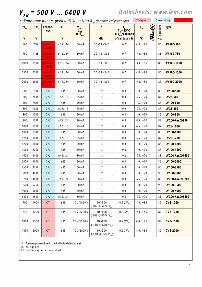
① See response time in the individual data sheet.recognizedon the way to be recognized
Datasheets: wwwDatasheets: wwwDatasheets: wwwDatasheets: wwwDatasheets: www.lem.com.lem.com.lem.com.lem.com.lem.comCT-types Closed-loop AV
Pac
kagi
ngP
acka
ging

24
8888888888
89
86
90
88
Voltage Transducers
Selection parameter 9: Measuring Accuracy Selection parameter 9: Measuring Accuracy Selection parameter 9: Measuring Accuracy Selection parameter 9: Measuring Accuracy Selection parameter 9: Measuring Accuracy
IGBT commutation generates voltage variations withhigh dv/dt levels. These fluctuations may induce errorson the output signal of voltage transducers. LEM hasdeveloped special versions of transducers with a screenbetween the primary and the secondary circuit,significantly reducing the error generated by theseperturbations.
Addressing EMCAddressing EMCAddressing EMCAddressing EMCAddressing EMC
The screen is a standard feature on several series ofvoltage transducers (CV3, AV 100, LV 200-AW/2), and isavailable as an option on LV 100 series.
Multiple package configurationsMultiple package configurationsMultiple package configurationsMultiple package configurationsMultiple package configurationsCustom-tailored solutions for current and voltage measurement.
Accuracy is a fundamental parameter in electrical systems.Selecting the right transducer is often a trade-off betweenseveral parameters: accuracy, frequency response, weight,dimensions, costs... The measuring accuracy for LEMtransducers depends primarily on the operation principle.
Open Loop transducers are calibrated during the manufacturingprocess and typically provide an accuracy better than 2 % ofthe nominal range at 25 °C. For additional offset and gain driftparameter, please refer to individual datasheets.
New ASIC based Open Loop and Eta transducers are beingdeveloped to provide improvement in gain and offset drift overtraditional Open Loop transducers.
Closed Loop current and voltage transducers provide excellentaccuracy at 25 °C, in general below 1 % of the nominal range,and a reduced error over the specified temperature range,thanks to their balanced flux operation.
IT and CT types are high performance transducers withexceptional accuracy level over their operating temperaturerange.
Individual datasheets provide all relevant information toprecisely calculate the overall accuracy of a given transducer ina specific application.
25
VVVVVPNPNPNPNPN = 500 V ... 6400 V = 500 V ... 6400 V = 500 V ... 6400 V = 500 V ... 6400 V = 500 V ... 6400 V
±V±V±V±V±VPNPNPNPNPN ±V±V±V±V±VPPPPP Techno-Techno-Techno-Techno-Techno- VVVVVCCCCC VVVVVOUTOUTOUTOUTOUT fffff XXXXXGGGGG TTTTTAAAAA TypeTypeTypeTypeTypelogylogylogylogylogy IIIIIOUTOUTOUTOUTOUT TTTTTA A A A A = 25°C= 25°C= 25°C= 25°C= 25°C
@ V@ V@ V@ V@ VPNPNPNPNPN @ V@ V@ V@ V@ VPNPNPNPNPN with max with max with max with max with max
VVVVV VVVVV VVVVV kHzkHzkHzkHzkHz offset taken %offset taken %offset taken %offset taken %offset taken % °C°C°C°C°C No.No.No.No.No.
500 750 Isolation ± 12...24 50 mA DC-13 (-3dB) 0.7 -40...+85 85 AV 100-500AV 100-500AV 100-500AV 100-500AV 100-500Amplifier
750 1125 Isolation ± 12...24 50 mA DC-13 (-3dB) 0.7 -40...+85 85 AV 100-750AV 100-750AV 100-750AV 100-750AV 100-750Amplifier
1000 1500 Isolation ± 12...24 50 mA DC-13 (-3dB) 0.7 -40...+85 85 AV 100-1000AV 100-1000AV 100-1000AV 100-1000AV 100-1000Amplifier
1500 2250 Isolation ± 12...24 50 mA DC-13 (-3dB) 0.7 -40...+85 85 AV 100-1500AV 100-1500AV 100-1500AV 100-1500AV 100-1500Amplifier
2000 3000 Isolation ± 12...24 50 mA DC-13 (-3dB) 0.7 -40...+85 85 AV 100-2000AV 100-2000AV 100-2000AV 100-2000AV 100-2000Amplifier
500 750 C/L ±15 50 mA ① 0.8 0...+70 86 LV 100-500LV 100-500LV 100-500LV 100-500LV 100-500
600 900 C/L ±12...15 25 mA ① 0.9 -25...+70 87 LV 25-600LV 25-600LV 25-600LV 25-600LV 25-600
600 900 C/L ±15 50 mA ① 0.8 0....+70 86 LV 100-600LV 100-600LV 100-600LV 100-600LV 100-600
800 1200 C/L ±12...15 25 mA ① 0.9 -25...+70 87 LV 25-800LV 25-800LV 25-800LV 25-800LV 25-800
800 1200 C/L ±15 50 mA ① 0.8 0...+70 86 LV 100-800LV 100-800LV 100-800LV 100-800LV 100-800
800 1200 C/L ±15...24 80 mA ① 0.8 -25...+70 88 LV 200-AW/2/800LV 200-AW/2/800LV 200-AW/2/800LV 200-AW/2/800LV 200-AW/2/800
1000 1500 C/L ±12...15 25 mA ① 0.9 -25...+70 87 LV 25-1000LV 25-1000LV 25-1000LV 25-1000LV 25-1000
1000 1500 C/L ±15 50 mA ① 0.8 0...+70 86 LV 100-1000LV 100-1000LV 100-1000LV 100-1000LV 100-1000
1200 1800 C/L ±12...15 25 mA ① 0.9 -25...+70 87 LV 25-1200LV 25-1200LV 25-1200LV 25-1200LV 25-1200
1200 1800 C/L ±15 50 mA ① 0.8 0...+70 86 LV 100-1200LV 100-1200LV 100-1200LV 100-1200LV 100-1200
1500 2250 C/L ±15 50 mA ① 0.8 0...+70 86 LV 100-1500LV 100-1500LV 100-1500LV 100-1500LV 100-1500
1600 2400 C/L ±15...24 80 mA ① 0.8 -25...+70 88 LV 200-AW/2/1600LV 200-AW/2/1600LV 200-AW/2/1600LV 200-AW/2/1600LV 200-AW/2/1600
2000 3000 C/L ±15 50 mA ① 0.8 0...+70 86 LV 100-2000LV 100-2000LV 100-2000LV 100-2000LV 100-2000
2500 3750 C/L ±15 50 mA ① 0.8 0...+70 90 LV 100-2500LV 100-2500LV 100-2500LV 100-2500LV 100-2500
3000 4500 C/L ±15 50 mA ① 0.8 0...+70 90 LV 100-3000LV 100-3000LV 100-3000LV 100-3000LV 100-3000
3200 4800 C/L ±15...24 80 mA ① 0.8 -25...+70 88 LV 200-AW/2/3200LV 200-AW/2/3200LV 200-AW/2/3200LV 200-AW/2/3200LV 200-AW/2/3200
3500 5250 C/L ±15 50 mA ① 0.8 0...+70 90 LV 100-3500LV 100-3500LV 100-3500LV 100-3500LV 100-3500
4000 6000 C/L ±15 50 mA ① 0.8 0...+70 90 LV 100-4000LV 100-4000LV 100-4000LV 100-4000LV 100-4000
6400 9600 C/L ±15...24 80 mA ① 0.8 -25...+70 88 LV 200-AW/2/6400LV 200-AW/2/6400LV 200-AW/2/6400LV 200-AW/2/6400LV 200-AW/2/6400
700 1000 CT ±15 10 V/1000 V DC-500 0.2 @VP -40...+85 89 CV 3-1000CV 3-1000CV 3-1000CV 3-1000CV 3-1000(-1dB @ 50 % VPN)
840 1200 CT ±15 10 V/1200 V DC-800 0.2 @VP -40...+85 89 CV 3-1200CV 3-1200CV 3-1200CV 3-1200CV 3-1200(-1dB @ 40 % VPN)
1000 1500 CT ±15 10 V/1500 V DC-800 0.2 @VP -40...+85 89 CV 3-1500CV 3-1500CV 3-1500CV 3-1500CV 3-1500(-1dB @ 33% VPN)
1400 2000 CT ±15 10 V/2000 V DC-300 0.2 @VP -40...+85 89 CV 3-2000CV 3-2000CV 3-2000CV 3-2000CV 3-2000(-1dB @ 25% VPN)
① See response time in the individual data sheet.recognizedon the way to be recognized
Voltage transducers (with built in resistor R1) (Mechanical mounting)
Datasheets: wwwDatasheets: wwwDatasheets: wwwDatasheets: wwwDatasheets: www.lem.com.lem.com.lem.com.lem.com.lem.comCT-types Closed-loop AV
Pac
kagi
ng