current and emerging technology for powering small
TRANSCRIPT
I I I I I I I I I I I I I I I I I I I
CURRENT AND EMERGING TECHNOLOGY FOR POWERING SMALL SATELLITES WITH SECONDARY CELLS AND BATTERIES
G. C. Klein and D. F. Schmidt Gates Aerospace Batteries
Gainesville, Florida
Abstract
Gates Aerospace Batteries [GAB] is currently participating in the full range of small and large satellites with a variety of products from three electrochemical technologies of NiCd, NiMH and NiHz In this presentation we discuss the role of small capacity cells [nominally 17 A-H and less] from those three electrochemical technologies. NiCd is of course the oldest technology. GAB's Survivability Database contains a total of 117 spacecraft with approximately 644 Total Mission Years of successful NiCd performance without a recorded failure. We continue to update this technology with improved plate designs and non-nylon separators to improve both performance and survivability. Nickel-metal hydride [NiMH] is one emerging technology that appears amenable for powering small spacecraft. In this technology, we literally replace the cadmium or negative electrode from NiCd technology with the metal-hydride electrode to form this new electrochemical couple. NiMH technology provides a reduction in both weight and volume as compared to NiCd technology. NiHz Planar Technology is another emerging technology that appears amenable for powering small spacecraft. In this technology, GAB has combined the superior capability of the nickel-hydrogen electrochemistry with the simplicity and design heritage of the mature NiCd product line. Again, GAB's success with this technology is based upon the expertise and heritage of the NiCd and NiHz programs.
1
1.0 Introduction
Gates Aerospace Batteries has participated on flight programs for over twenty-five years. This includes Nickel-Cadmium cells and Nickel-Hydrogen cells in more than three hundred satellites either launched or in the planning. This overview will demonstrate our commitment to the quality and reliability of these designs, as well as extending our capability with two emerging technologies.
Gates has demonstrated its capability to produce very reliable pressure v,essel and packaging designs featuring the truly hermetic Ceramic-Metal Seal. This seal is used in the four technologies that Gates Aerospace Batteries is currently manufacturing, three of which are discussed in this paper.
This paper summarizes Gates' position on cell and battery technologies to support the emerging small satellite market. Accordingly, the following discussions center upon capabilities in the nominally smaller cells of 17 A-H capacity and below. The approach taken is to describe the technology and its current status, and then any further advancements that are being developed. Necessarily, this overview is generic in nature and references many sensitive and proprietary documents that can be supplied in a non-competitive environment.

2.0 NiCd Technology
Nickel-Cadmium [NiCd] Technology is alive and well at Gates Aerospace Batteries [GAB]. GAB is committed to both the existing mature NiCd designs as well as advanced NiCd designs using improved electrodes and separators.
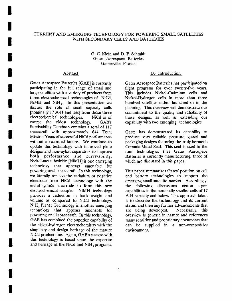
NiCd is of course the oldest technology. We continue to update this technology with improved plate designs and non-nylon separators to improve both performance and survivability. We continue to perform basic Reliability Analyses and Assessments to support this technology. A short listing of NiCd design examples is shown in Figure 1. A typical NiCd battery is also shown.
Government and industry environmental concern with cadmium metal has already been resolved and we expect NiCd technology to be a viable contender for powering spacecraft for sometime. Our current production commitments include 12A-H cells for the Space Systems/LORAL GOES Program wherein Flight M is scheduled. for delivery as late as 2001.
Gates' Survivability Database
GAB's Survivability Database contains many superlatives expressing the heritage and maturity of this technology and the product line I,
For 6 A-H capacity and below, Gates, and its direct predecessor General Electric, have accumulated approximately 338 Total Mission Years of successful NiCd performance on 66 spacecraft without a recorded failure. For 17 A-H capacity and below, 117 spacecraft have accumulated approximately 644 Total Mission Years of successful performance without a recorded failure. This 644 Total Mission Years is equivalent to:
2
259 LEO Mission Years, 385 Total Mission Years, 0.23 million Total Mission Days, 5.64 million Total Mission Hours, or 248 million Total Cell Hours.
Assume that five years in LEO environment [29,200 cycles] is a typical mission lifetime requirement. Then several superlatives can be shown. First, 24 of the LEO missions analyzed were operated beyond that benchmark including one mission for 22 years. Second, testing of a four-cell pack of 26 A-H cells achieved 11.7 years [68,110 cycles] last year in a LEO test regime. This cell pack was under test at Crane-NSWC at 10°C and 20% DOD.
Reliability Analyses and Assessments
Gates continues to perform and update a variety of generic and program Reliability Analyses and Assessments. Predominantly, these include the aforementioned numerical analysis of survivability, and then the FMECA and PTA These analyses are still important even at this mature stage of development as we adopt Concurrent Engineering and other Total Quality Management techniques. The knowledge gained here allows us to resolve potential problems in a parallel fashion rather than encountering each problem as a serial tollgate.
Failure Modes, Effects and Criticality Analysis
The Failure Modes, Effects and Criticality Analysis [FMECA] involves the listing of potential failure modes, their cause, and their effect upon the components, sub-systems, and systems. Another measure incorporated is the criticality of the failure mode as regards personnel safety, mission success, system performance degradation, etc. This FMECA is a "bottoms-up" analysis of the product design characteristics relative to the planned fabrication, test, and inspection process to ensure that the resultant product meets the intended need, expectation and performance
I I I I I I I I I I I I I I I I I I I

I I I I I I I I I I I I I I I I I I I
goals. The latest NiCd FMECA was performed in conjunction with a baseline assessment for Nickel-Metal Hydride activities. This occurred during the recent transfer of this NiMH technology from R&D to full scale production.
Fault Tree Analysis
Fault Tree Analysis [FTA] is the process of reviewing and analytically examining a system or equipment in such a way as to emphasize the lower-level fault occurrences which directly or indirectly contribute to the major fault or undesired event. The value of the FTA is that by developing the lower-level failure mechanisms necessary to realize higher level occurrence, a total overview of the system is achieved. This is considered to be a "top-down" approach by which each level of fault is expanded to its required input occurrence until a primary occurrence is defined. A NiCd FTA was completed in December 1992 and contains fifteen years of lessons learned ~ Accordingly, this FTA is proprietary.
3.0 NiMH Technology
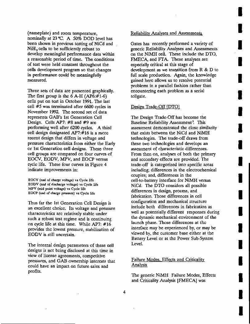
Nickel-metal hydride [NiMH] is one emerging technology that appears amenable for powering small spacecraft. In this technology, we literally replace the cadmium or negative electrode from NiCd technology with the metal-hydride electrode to form this new electrochemical couple. NiMH technology provides a significant reduction in both weight and volume as compared to NiCd and NiH2 technology as shown in Figure 2. Expected cycle life may be equal to or greater than NiCd for certain applications, as also shown by Figure 2. GAB's success with this technology is based upon the tremendous expertise and heritage of the mature NiCd flight programs. This experience together with a full complement of preliminary reliability analyses and assessments will virtually guarantee a successful transition from NiCd to NiMH for those applications demanding decreased weight
3
and volume. A typical NiMH battery configuration is identical to that NiCd battery shown in Figure 1.
In-House Test Program
A first generation cell design has been selected based on the many cell designs that have been subjected to a standard LEO life test cycle of 50% DOD and 23 "C.
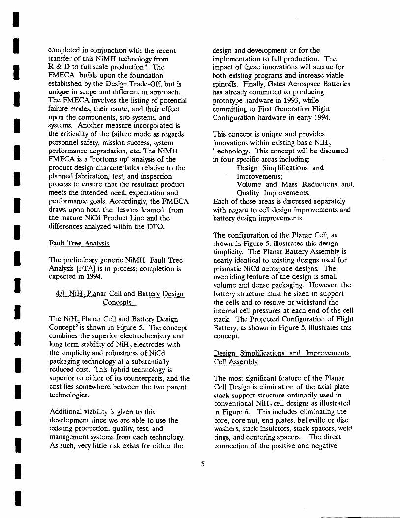
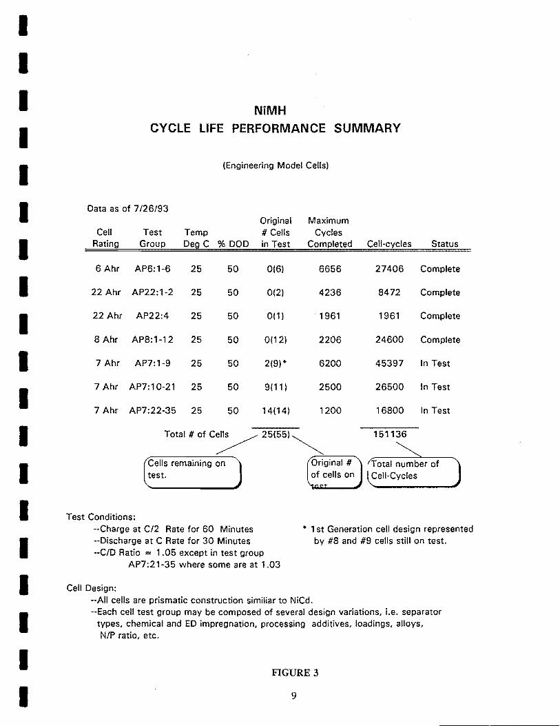
Figure 3 shows a tabulation of the fifty-five (55) cells in the GAB test program. Twentyfive (25) cells are continuing the life test.
Additional cells are being added to the program on a periodic basis in order to validate new design parameters. Cell test data, predominantly LEO life cycle testing, has been reported at various customer meetings, the NASA Battery Workshop, the AF Space Power Workshop~ and in GAB's NiMH Product Information binder.
The cells built for the test program have involved a great number of design variables such as positive electrode types and impregnation, AB:2 and AB 5 negative electrodes, electrode processing and treatments, and at least 6 different separators. Each group of cells shown in Figure 3 contains one or two cells built with the same design variable.
Life cycling for all cells in the table were performed in a 90 minute simulation regime of 35 minutes discharge and 55 minutes charge using an integrator controlled cycler. Each cell is monitored using a FLUKE scanning multi meter interfaced to a PC based data collection system. Cell pressures are monitored by direct reading of gauges (Ashcroft A1S1) attached to the cells. Pressure data is manually entered into the correct data file. The specific test conditions are shown on Figure 3.
(nameplate) and room temperature, nominally at 23 ce. A 50% DOD level has been shown in previous testing of NiCd and NiH2 celIs to be sufficiently robust to develop meaningful performance data within a reasonable period of time. The conditions of test were held constant throughout the celIs development program so that changes in performance could be meaningfully measured.
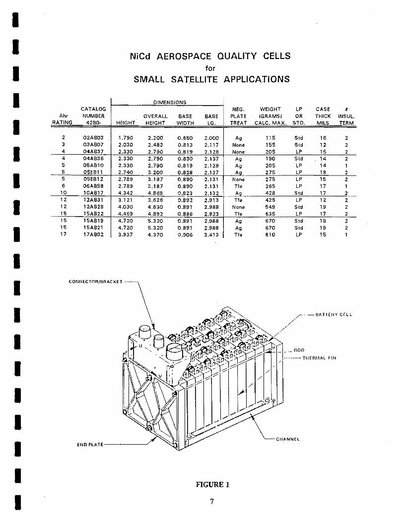
Three sets of data are presented graphically. The first group is the 6 A-H (AP6:#1-6) celIs put on test in October 1991. The last cell #5 was terminated after 6600 cycles in November 1992. The second set of data represents GAB's 1st Generation Cell Design. Cells AP7: #8 and #9 are performing well after 6200 cycles. A third cell design designated AP7:#16 is a more recent design that differs in voltage and pressure characteristics from either the Early or 1st Generation cell designs. These three cell groups are compared on four curves of EOCV, EODV, MPV, and EOCP versus cycle life. These four curves in Figure 4 indicate improvements in:
EOCV (end of charge Voltage) vs Cycle life EODV (end of discharge voltage) vs Cycle life MPV (mid point Voltage) vs Cycle life EOCP (end of charge pressure) vs Cycle life
Thus far the 1st Generation Cell Design is an excellent choice. Its voltage and pressure characteristics are relatively stable under such a robust test regime and is continuing on cycle life at this time. While AP7: #16 provides the lowest pressure, stabilization of EODV is still uncertain.
The internal design parameters of these cell designs is not being disclosed at this time in view of license agreements, competitive pressures, and GAB ownership interests that could have an impact on future sales and profits.
4
Reliability Analyses and Assessments
Gates has recently performed a variety of generic Reliability Analyses and Assessments on the NiMH cell. These include the DTO, FMECA, and FTA These analyses are especially critical at this stage of development as we transition from R&D to full scale production. Again, the knowledge gained here allows us to resolve potential problems in a parallel fashion rather than encountering each problem as a serial tollgate.
Design Trade-Off [PTO]
The Design Trade-Off has become the Baseline Reliability Assessment s. This assessment demonstrated the close similarity that exists between the NiCd and NiMH technologies. The trade-off draws from these two technologies and develops an assessment of characteristic differences. From then on, analyses of both the primary and secondary effects are provided. The trade-off is categorized into specific areas including: differences in the electrochemical couples; and, differences in the cell-to-battery interface for NiMH versus NiCd. The DTO considers all possible differences in design, process, and fabrication. Those differences in cell configuration and mechanical structure include both differences in fabrication as well as potentially different responses during the dynamic mechanical environment of the launch phase. Those differences at the interface may be experienced by, or may be viewed by, the customer base either at the Battery Level or at the Power Sub-System Level.
Failure Modes, Effects and Criticality Analysis
The generic NiMH Failure Modes, Effects and Criticality Analysis [FMECA] was
I I I I I I I I I I I I I I I I I I I
I I I I I I I I I I I I I I I I I I I
completed in conjunction with the recent transfer of this NiMH technology from R&D to full scale production 4. The FMECA builds upon the foundation established by the Design Trade-Off, but is unique in scope and different in approach. The FMECA involves the listing of poteIitial failure modes, their cause, and their effect upon the components, sub-systems, and systems. Another measure incorporated is the criticality of the failure mode as regards personnel safety, mission success, system performance degradation, etc. The NiMH FMECA is a "bottoms-up" analysis of the product design characteristics relative to the planned fabrication, test, and inspection process to ensure that the resultant product meets the intended need, expectation and performance goals. Accordingly, the FMECA draws upon both the lessons learned from the mature NiCd Product Line and the differences analyzed within the DTO.
Fault Tree Analysis
The preliminary generic NiMH Fault Tree Analysis [FTA] is in process; completion is expected in 1994.
4.0 NiH2 Planar Cell and Battery Design Concepts
The NiH2 Planar Cell and Battery Design Concept2 is shown in Figure 5. The concept combines the superior electrochemistry and long term stability of NiH2 electrodes with the simplicity and robustness of NiCd packaging technology at a substantially reduced cost. This hybrid technology is superior to either of its counterparts, and the cost lies somewhere between the two parent technologies.
Additional viability is given to this development since we are able to use the existing production, quality, test, and management systems from each technology. As such, very little risk exists for either the
5
design and development or for the implementation to full production. The impact of these innovations will accrue for both existing programs and increase viable spinoffs. Finally, Gates Aerospace Batteries has already committed to producing prototype hardware in 1993, while committing to First Generation Flight Configuration hardware in early 1994.
This concept is unique and provides innovations within existing basic NiHz Technology. This concept will be discussed in four specific areas including:
Design Simplifications and Improvements; Volume and Mass Reductions; and, Quality Improvements.
Each of these areas is discussed separately with regard to cell design improvements and battery design improvements.
The configuration of the Planar Cell, as shown in Figure 5, illustrates this design simplicity. The Planar Battery Assembly is nearly identical to existing designs used for prismatic NiCd aerospace designs. The overriding feature of the design is small volume and dense packaging. However, the battery structure must be sized to support the cells and to resolve or withstand the internal cell pressures at each end of the cell stack. The Projected Configuration of Flight Battery, as shown in Figure 5, illustrates this concept.
Design Simplifications and Improvements Cell Assembly
The most significant feature of the Planar Cell Design is elimination of the axial plate stack support structure ordinarily used in conventional NiHz cell designs as illustrated in Figure 6. This includes eliminating the core, core nut, end plates, belleville or disc washers, stack insulators, stack spacers, weld rings, and centering spacers. The direct connection of the positive and negative

electrode tabs to the terminal bus bar eliminates lengthy tab extensions of the current axial designs.
From the standpoint of Total Parts Count Reliability Analysis, the Planar Cell is clearly more reliable. This is because the Planar Design totally eliminates 18 different types of component parts. Other numerous small component parts were re-configured and enlarged to further reduce the total parts count. Thus, the piece part count for the Planar Design is approximately 90+ component parts versus 180+ for the typical 36A-H NiH:z cell of axial or conventional design.
Cell terminals may be oriented at either 90 degrees or at 180 degrees. This terminal configuration improves the balance of individual electrode equi-potentials during discharge to improve both mid-point and end-point voltage responses. Piece part count for the planar design is reduced approximately 75% versus the conventional NiH:z design.
Battery Assembly
An example of a typical flight configuration battery is illustrated in Figure 6. The features of this design include large flat surfaces of the cell to allow simplified and compact battery designs similar to current NiCd battery designs. The more compact battery design allows use of shorter inter-cell connectors. Clearly, this battery configuration is virtually identical to that for NiCd batteries shown in Figure 1.
Volume and Mass Reductions Cell Assembly
The anticipated volume and mass reductions for the Planar Design comes from two areas. This design eliminates a total of 18 different types of component parts. Numerous other small component parts
6
were re-configured and enlarged to further reduce the total parts count. With this elimination of component parts came the weight and volume reductions.
For a conventional 36 A-H design with a weight of 942 grams, elimination of the axial stack support system results in a mass reduction of 124 grams; elimination of the tab extensions results in a mass reduction of 24 grams.
Gates does not have conventional or axial design NiH:z cells below the cited 36 A-H cell. However, the below table illustrates typical small capacity designs of the Planar cell currently being developed.
Capacity, Weight, Volume, A-H grams cc
5 160 104 7 194 137 15 354 257 30 625 500
Volume and Mass Reductions - Battery Assembly
The simplified and compact battery design eliminates the present captive-cell, space frame oriented battery designs. Projected battery volumes with resultant Energy Densities and projected battery weights with resultant Specific Energies are speculative at this point.
Quality Improvements Cell Assembly
The anticipated improvements in quality effectiveness for this design occur mainly from the reduction of component parts. Elimination of the axial plate stack support structure reduces the technical interface to control and manage 18 specific piece parts or (Continued on page 14 ... )
I I I I I I I I I I I I I I I I I I I
I I I I I I I I I I I I I I I I I I I
CATALOG Ahr NUMBER
RATING 42BO-
2 02AB03 3 03AB07 4 04AB37 4 04AB36 5 05AB10 5 05EB11 5 05EB12 6 06AB58 10 10AB17 12 12AB31 12 12AB28 15 15AB22 15 15AB19 15 15AB21 17 17AB02
NiCd AEROSPACE QUALITY CELLS for
SMALL SATELLITE APPLICATIONS
DIMENSIONS NEG. WEIGHT
OVERALL BASE BASE PLATE (GRAMS) HEIGHT HEIGHT WIDTH LG. TREAT CALC. MAX.
1.790 2.200 0.650 2.000 Ag 115 2.030 2.483 0.813 2.117 None 155 2.330 2.790 0.819 2.128 None 205 2.330 2.790 0.830 2.137 Ag 190 2.330 2.790 0.819 2.128 Ag 205 2.740 3.200 0.828 2.137 Ag 275 2.789 3.187 0.890 2.131 None 275 2.789 3.187 0.890 2.131 Tfe 265 4.342 4.869 0.823 2.132 Ag 428 3.121 3.626 0.892 2.913 Tfe 425 4.030 4.630 0.891 2.988 None 549 4.469 4.892 0.886 2.923 Tfe 635 4.720 5.320 0.891 2.988 Ag 670 4.720 5.320 0.891 2.988 Ag 670 3.937 4.370 0.906 3.4 13 Tfe 610
LP CASE # OR THICK INSUL.
STD. MILS TERM
Std 16 2 Std 12 2 LP 15 2
Std 14 2 LP 14 1 LP 19 2 LP 15 2 LP 17 1 Std 17 2 LP 12 2 Std 19 2 LP 17 2 Std 19 2 Std 19 2 LP 15 1
CONN ECT(lfl/UflAC KE T
~UATHnY CELL
/ /"
/
TlIEm.1AL FIN
CIIANNEL END PlATE------/
FIGURE 1
7

60
55
50
~ 45 -en ... J: 3: 40
35
30
25 0
I I
ISPECIFIC ENERGY COMPARISON, I ENERGY DENSITY COMPARISONI I
V) W ...I (.)
> (.)
u.. 0 0:: w CD ~ ::::> z
20 40
CAPACITY. Ahrs
10000
1000
190
170
150
... 130 CI)
.t::
...I - 110 en ... J: 3: 90
A
./ ~ "V
if .----- NiCd
~
NiH2( 70 ~ ~NiH2(
EO}
EO)
50
30 60 o
TYPICAL LEO LIFE CYCLE PERFORMANCE OF VARIOUS
CELL TYPES
i-'
20 40 60
CAPACITY. Ahrs
100+-~~~+-~~~4---~--4-~~~~~~--~
o 20 40 60 80 100
% DEPTH OF DISCHARGE
FIGURE 2
8
I I I I I I I I I I I I I I I I
I I I I I I I I I I I I I I I I I I I
NiMH CYCLE LIFE PERFORMANCE SUMMARY
(Engineering Model Cells)
Data as of 7/26/93 Original Maximum
Cell Test Temp # Cells Cycles Rating Group Deg C % DOD in Test Completed Cell-cycles Status
6 Ahr AP6:1-6 25 50 0(6) 6656 27406 Complete
22 Ahr AP22:1-2 25 50 0(2) 4236 8472 Complete
22 Ahr AP22:4 25 50 0(1) 1961 1961 Complete
8 Ahr AP8:1-12 25 50 0(12) 2206 24600 Complete
7 Ahr AP7:1-9 25 50 2(9)* 6200 45397 In Test
7 Ahr AP7:10-21 25 50 9(11) 2500 26500 In Test
7 Ahr AP7:22-35 25 50 14(14) 1200 16800 In Test
Total # of C/ 25(55) ~ 151136
Cells remaining on Total number of test. Cell-Cycles
Test Conditions: --Charge at C/2 Rate for 60 Minutes --Discharge at C Rate for 30 Minutes
* 1 st Generation cell design represented by #8 and #9 cells still on test.
--C/D Ratio = 1.05 except in test group AP7:21-35 where some are at 1.03
Cell Design: --All cells are prismatic construction simi liar to NiCd. --Each cell test group may be composed of several design variations, i.e. separator
types, chemical and ED impregnation, processing additives, loadings, alloys, N/P ratio, etc.
FIGURE 3
9

COMPARISON OF EARLY TO PRESENT CELLS
IMPROVEMENTS IN EOCV IMPROVEMENTS IN EODV Early-Present Cell Designs Early-Present Cell Designs
1.60 1.20
~ 'Ht)
Early Call 1st G neration ~ell
1.55 ....... 1.15 ,1)7· 8.9
~ ~.
1""'- ... ~~ I~ 1.50 1.10 v- ~
(J) ~~.A ~- ----~ (J) ~ .... 1 - ~ lEartv Cell -J 1.45 Cell 1.05 0
- JIitj ~ AP7: 8, 0 M>S:'5 > r- - >
1.40 I IID"1.1/1 I", 1.00
1.35 0.95
1.30 ITests at 50% DOD and 25° ci
0.90 Tests at 50% DOD and 25° C
0.0 2.0 4.0 6.0 8.0 0.0 2.0 4.0 6.0 8.0
CYCLES IN THOUSANDS CYCLES IN THOUSANDS
IMPROVEMENTS IN MPV CELL PRESSURE REDUCTION
Early -Present Cell Designs Early-Present Cell Designs
140 If 1.3
Tests at 50% DOD and 25 0 ci '- AP7: '1€ I arly Cell 120
E:~ ~ells 1.3 :- IJo\ro: ::> « 100 ! en II"'
A -V"",, 00
I / 1.2 I' 11;- ~ Ul 1st G ~neration C 80 :/ .... ~?7~ 8.9 W -J 1.2 a:: 0 :::> 60 ! > (J) / 1.1 (J)
40 w ~ a: .r-Oo
1.1 20 .- 1 t Generati n C
Tests at 50% DOD and 25 O C\ 1- AP7: 8 9 AP7 #16
1.0 0 0.0 2.0 4.0 6.0 8.0 0.0 2.0 4.0 6.0 8.0
CYCLES IN THOUSANDS CYCLES IN THOUSANDS
Note: Electrolyte adjustment made at approx. 2400 cycles on 1 st Generation Cells.
FIGURE 4
10
I I I I I I I I I I I I I I I I I I I

I I I I I I I I I I I I I I I I I I I
Positive Terminal
Pressure Vessel Cylinder
Pressure Vessel Disk
Insulating Protective End Cap (Both Ends)
Planar Cell - Cut Away
Connectors lor: - Battery Monitoring - Battery Heaters - Battery Conditioning
Tab-To-Comb Weldments
Plate Pack ---.",.....':::::::'--,
Gauges
Polypropylene Pack Wrapper
Terminal and Adapter Assembly (Same as NiH2 Cell)
Secondary Comb
Primary Comb
Plate Tab
Electrode (Plate)
ERP
Polypropylene Pack Wrapper
Electrode
Internal Pack Support and Volume Restraint
Flight Configuration Battery (Planar Cells)
- Battery Power (on reverse side)
(Pressure monitoring. 2 places)
22 Cells arranged 2 x 11
Cell Monitoring (one shown for clarity)
Thermal Fins between each cell
Note: heaters in thermal fins
Intercell Connectors
Radiator & Baseplate
FIGURE 5
11
Tie Bars (3 places)
Active Restraint (6 places each end)
Ribbed Restraint Plates (Both ends)

II
H "
PLATE: SrACK AREA
L .. _. ___ . _____ . ____ ..
POS.IT/VE7 TAB L£AlJS
nu TOBE~ BOTH ENM
CERAMIC SEAL AREA J :n.'NIC SEA~;:A-
H.Kf::MrIr.E-. rS.N.VIHA£
S.JTSJZN'A£ IHSQlirIHC CAF BorN rS&VI.HALS
C.E.lU.VIC SSA£ A.RKA
ENlJ LOA.lJINC ' IfELlJ R/NC
. .JREAS
NiH2 Axial Configuration
I I
/
r"SLlJ mAC / .~crUHLJS.N-
.rl Plirs srAcK ai" A~A tI f , , ___ lL ____________________ _
'- '---41H ::
NiH2 Rabbit Ear Configuration (Patent Pending)
FIGURE 6
12
co~
I I I I I I I I I I I I I I I I I I I

I I I I Specific Energy (Weight Related)
of Various Cell Types
I 70
60
I 50 IPV
NIH2 01
40 ~ -I
(1.1 "-.s:: 30 :=
20
I 10
0
I 5 30 100
CAPACITY IN Ahrs
I I Energy Density (Volume Related)
of Various Cell Types
I 140
120
I 100 "-<1.1 .... 80 iiE
I (1.1 "- 60 .s:: :=
40
I 20
0
I 5 30 100
CAPACITY IN Ahrs
I I
FIGURE 7
I 13
(Continued from page 6 ... ) part numbers. Elimination of the axial plate stack support structure and tab extensions
eliminates the present complex plate stacking operation. Cell performance and reliability, as measured by Thermal Management, Electrolyte Management, and Gas Management are significantly improved.
Battery Assembly
The simplified battery design will result in reduced fabrication and assembly errors. Overall thermal management of the battery assembly will be improved. Finally, this design is more robust as regards the Dynamic Mechanical Environment.
5.0 Summary
Specific Energy is a term used to index or normalize the power-to-weight ratio across different cell designs and electrochemistries. The first chart of Figure 7, titled "Specific Energy (Weight Related) of Various Cell Types", dramatically illustrates the improvement in this performance ratio for the Planar Cell over the two parent technologies. Likewise, Energy Density is a term used to index or normalize the volume-to-weight ratio across different cell designs and electrochemistries. The second chart of Figure 7, titled "Energy Density (Volume Related) of Various Cell Types", dramatically illustrates the improvement in this perforIilance ratio for the Planar Cell over conventional NiH2 Technologies.
Whatever the key design parameters are for your particular satellite program, Gates Aerospace Batteries has the product to satisfy volume, weight, cost and performance requirements.
14
6.0 References
1) Denson, William K., and Klein, Glenn C., MCd Cell Reliability in the Mission Environment; Proceedings of the 1992 NASA Aerospace Battery Workshop, NASA Conference Publication 3192.
2) Klein, Glenn C., Executive Summary: MH2 Planar Cell and Battery Design Concepts; Proprietary Documentation privately printed and distributed. Gates Aerospace Batteries, Gainesville, Florida; July 23, 1993.
3) Klein, Glenn C., MCd Fault Tree Analysis; Proprietary Documentation privately printed and distributed, Gates Aerospace Batteries, Gainesville, Florida; Dec. 14, 1992.
4) Klein, Glenn C., Preliminary Failure Modes, Effects and Criticality Analysis of the MMH Cell for. Aerospace Batteries; Proceedings of the 1993 IECEC, Atlanta, Georgia.
5) Klein, Glenn C., Preliminary Reliability Analyses and Assessments of the MMH Cell for Aerospace Batteries; Proceedings of the 1992 IECEC, San Diego, California.
6) Schmidt, David F., and Klein, Glenn C.; MMH Battery Cell Development for Spacecraft Applications, 1993 Space Power Workshop; Albuquerque, New Mexico.
I I I I I I I I I I I I I I I I I I I