curb ramp design guidelines v1.0 draft 083120
TRANSCRIPT

CURB RAMP DESIGN GUIDELINES Version 1.0 – September 10, 2020

CURB RAMP DESIGN GUIDELINES (V1.0-09.10.20)
Page | 2
Description Page Requirements 3 – 30
I. Background 3 II. Regulations 3 III. Definitions 4 IV. Application 9 V. Design Process 11 VI. Deviation from Standards Form and Technical Infeasibility
Form 26
Basic Curb Ramp Components 31 Curb Ramp Types 32 Slope and Width Requirements 33 - 35 Diagonal Curb Ramps (on the apex) 36 Perpendicular Grade Break Requirement 37 – 38 Curb and Gutter 39 – 42 Detectable Warning Surface 43 – 47 Perpendicular Curb Ramps 48 – 59 Parallel Curb Ramps 60 – 69 Blended Transitions 70 – 71 Curb Ramp Placement 72 – 77 Examples 78 - 87
DISCLAIMER: The information contained in this document does not constitute a City of San Diego standard and shall be for reference only. This document is to be used in conjunction with the most current and adopted City of San Diego Standard Drawings for Public Works Construction (City Standards).
CONTENTS

CURB RAMP DESIGN GUIDELINES (V1.0-09.10.20)
Page | 3
I. BACKGROUND:
Starting January 1, 2020, the California Code of Regulations (Title 24) require a curb ramp at each pedestrian crossing when triggered by new construction and alteration projects. If an existing curb return serves two pedestrian crossings (marked or unmarked), a separate curb ramp for each pedestrian crossing shall be installed to the maximum extent feasible. If a curb return serves a single pedestrian crossing, then a single curb ramp shall be installed. The single curb ramp shall be directional or, if placed within the curb return, at least shifted away from the apex of the curb return. The following guidelines are intended to assist you in the design of the most typical curb ramps. For technical assistance, you may contact Engineering and Capital Projects Department at [email protected].
II. REGULATIONS:
FEDERAL - The Americans with Disabilities Act of 1990 (ADA) is a civil rights statute that prohibits discrimination against people with disabilities. Implementing regulations for Title II of the ADA prohibit discrimination in the provision of services, programs, and activities by state and local governments. Designing and constructing pedestrian facilities in the public right-of-way (ROW) that are not usable by people with disabilities may constitute discrimination. Newly constructed or altered streets, roads, and highways must contain curb ramps at any intersection having curbs or other barriers to entry from a road, highway, or street level pedestrian walkway. 28 CFR § 35.151(i)(1).
STATE – Title 24 of the California Code of Regulations (2019 California Building Code (CBC)) § 11B-206.2.19 - Where walks or sidewalks are provided, a curb ramp, blended transition, or a combination of curb ramps and blended transitions complying with Section 11B-406 (Curb Ramps) shall connect the walks or sidewalks at each pedestrian street crossing. The curb ramp (excluding any flared sides) or blended transition shall be contained wholly within the width of the pedestrian street crossing served.
REQUIREMENTS

CURB RAMP DESIGN GUIDELINES (V1.0-09.10.20)
Page | 4
WHY DOES THE CBC APPLY TO THE PUBLIC RIGHT-OF-WAY (ROW)? Title 24, section 1.9 of the California Code of Regulations discusses the Division of the State Architect (DSA) and the application of the CBC. It references the California Government Code commencing with Section 4450. “It is the purpose of this chapter to ensure that all buildings, structures, sidewalks, curbs, and related facilities, constructed in this state by the use of state, county, or municipal funds, or the funds of any political subdivision of the state shall be accessible to and usable by persons with disabilities.” Cal. Gov’t Code § 4450(a) (emphasis added). “With respect to buildings, structures, sidewalks, curbs and related facilities not requiring a building permit, building standards published in the California Building Standards Code relating to access for persons with disabilities and other regulations adopted pursuant to Government Code Section 4450, and in effect at the time construction is commenced shall be applicable.” Cal. Code Regs. title 24, § 1.9.1.1.5 (emphasis added). Based on the authority stated in the California Code of Regulations and the California Government Code, the public right-of-way is subject to Chapter 11B of title 24 of the California Code of Regulations (CBC).
III. DEFINITIONS:
1. ALTERATION - A change to a building or facility that affects or could affect the usability of the building or facility or portion
thereof. Alterations include, but are not limited to, remodeling, renovation, rehabilitation, reconstruction, historic restoration, resurfacing of circulation paths or vehicular ways, changes or rearrangement of the structural parts or elements, and changes or rearrangement in the plan configuration of walls and full-height partitions. Normal maintenance, reroofing, painting, or wallpapering, or changes to mechanical and electrical systems are not alterations unless they affect the usability of the building or facility. 2010 ADA Standards for Accessible Design (ADA) § 106.5 Defined Terms.
A change to a facility in the public right-of-way that affects or could affect pedestrian access, circulation, or use. Alterations
include, but are not limited to, resurfacing, rehabilitation, reconstruction, historic restoration, or changes or rearrangement of structural parts or elements of a facility. United States Access Board, Proposed Accessibility Guidelines in the Public Right-of-Way (PROWAG) § R105.5 Defined Terms.
REQUIREMENTS
CURB RAMP DESIGN GUIDELINES (V1.0-09.10.20)
Page | 5
A change, addition, or modification in construction, change in occupancy or use, or structural repair to an existing building or facility. Alterations include, but are not limited to, remodeling, renovation, rehabilitation, reconstruction, historic restoration, resurfacing of circulation paths or vehicular ways, changes or rearrangement of the structural parts or elements, and changes or rearrangement in the plan configuration of walls and full-height partitions. CBC §§ 11B-106.5 Defined Terms, 202 Definitions.
An alteration is a change that affects or could affect the usability of all or part of a building or facility. Alterations of streets, roads, or highways include activities such as reconstruction, rehabilitation, resurfacing, widening, and projects of similar scale and effect. Maintenance activities on streets, roads, or highways, such as filling potholes, are not alterations. Department of Justice/Department of Transportation Joint Technical Assistance on the Title II of the Americans with Disabilities Act Requirements to Provide Curb Ramps when Streets, Roads, or Highways are Altered through Resurfacing.
2. BLENDED TRANSITION - A raised pedestrian street crossing, depressed corner, or similar connection between the pedestrian
access route at the level of the sidewalk and the level of the pedestrian street crossing that has a grade of 5 percent or less. CBC § 106.5 Defined Terms.
3. CURB RAMP -
A short ramp cutting through a curb or built up to it. ADA Standards § 106.5 Defined Terms. A sloping pedestrian way, intended for pedestrian traffic, which provides access between a walk or sidewalk and a surface
located above or below an adjacent curb face. CBC §§ 11B-106.5 Defined Terms, 202 Definitions. A ramp that cuts through or is built up to the curb. Curb ramps can be perpendicular or parallel, or a combination of parallel
and perpendicular ramps. PROWAG § R105.5 Defined Terms.
REQUIREMENTS

CURB RAMP DESIGN GUIDELINES (V1.0-09.10.20)
Page | 6
4. FACILITY -
All or any portion of buildings, structures, site improvements, elements, and pedestrian routes or vehicular ways located on a site. ADA Standards § 106.5 Defined Terms.
All or any portion of buildings, structures, sites, complexes, equipment, rolling rock or other conveyances, roads, walks, passageways, parking lots, or other real or personal property, including the site where the building, property, structure, or equipment is located. 28 CFR § 35.104 Definitions.
All or any portion of buildings, structures, improvements, elements, and pedestrian or vehicular routes located in the public right-of-way. PROWAG § R105.5 Defined Terms.
5. GRADE BREAK - The line where two surface planes with different grades meet. PROWAG § R105.5 Defined Terms.
6. MAXIMUM EXTENT FEASIBLE - The phrase "to the maximum extent feasible," as used in this section, applies to the occasional
case where the nature of an existing facility makes it virtually impossible to comply fully with applicable accessibility standards through a planned alteration. In these circumstances, the alteration shall provide the maximum physical accessibility feasible. Any altered features of the facility that can be made accessible shall be made accessible. If providing accessibility in conformance with this section to individuals with certain disabilities (e.g., those who use wheelchairs) would not be feasible, the facility shall be made accessible to persons with other types of disabilities (e.g., those who use crutches, those who have impaired vision or hearing, or those who have other impairments). 28 CFR § 36.402(c) Alterations.
7. PEDESTRIAN ACCESS ROUTE - A continuous and unobstructed path of travel provided for pedestrians with disabilities within or coinciding with a pedestrian circulation path. PROWAG § R105.5 Defined Terms.
8. PEDESTRIAN CROSSING (CROSSWALK) - (a) That part of a roadway at an intersection included within the connections of the lateral lines of the sidewalks on opposite
sides of the highway measured from the curbs or in the absence of curbs, from the edges of the traversable roadway, and
REQUIREMENTS

CURB RAMP DESIGN GUIDELINES (V1.0-09.10.20)
Page | 7
in the absence of a sidewalk on one side of the roadway, the part of a roadway included within the extension of the lateral lines of the sidewalk at right angles to the center line; (b) any portion of a roadway at an intersection or elsewhere distinctly indicated as a pedestrian crossing by pavement marking lines on the surface, which might be supplemented by contrasting pavement texture, style, or color. 2014 California Manual Uniform Traffic Control Devices Rev 5 § 1A.13 Definitions of Headings, Words, and Phrases.
(a) That portion of a roadway included within the prolongation or connection of the boundary lines of sidewalks at
intersections where the intersecting roadways meet at approximately right angles, except the prolongation of such lines from an alley across a street; (b) Any portion of a roadway distinctly indicated for pedestrian crossing by lines or other markings on the surface. Notwithstanding the foregoing provisions of this section, there shall not be a crosswalk where local authorities have placed signs indicating no crossing. Cal. Vehicle Code § 275.
9. SHARED-USE PATH:
The term shared–use path is defined by AASHTO as "a bikeway physically separated from motorized vehicular traffic by an
open space or barrier and either within the highway right–of–way or within an independent right–of–way. Shared–use paths may also be used by pedestrians, skaters, wheelchair users, joggers, and other nonmotorized users." These facilities are most commonly designed for two–way travel. In many communities, shared–use paths may also be referred to as trails, multiuse trails, bike paths, hiker/biker trails, or other similar terms. US Department of Transportation, Federal Highway Administration University Course on Bicycle and Pedestrian Transportation, Lesson 19: Greenways and Shared-Use Paths (July 2006) § 19.2.
Shared use paths are multi-use paths designed primarily for use by bicyclists and pedestrians, including pedestrians with
disabilities, for transportation and recreation purposes. Shared use paths are physically separated from motor vehicle traffic by an open space or barrier, and are either within the highway right-of-way or within an independent right-of-way. PROWAG, Shared Use Paths, Supplemental Notice of Rulemaking, Summary (February 13, 2013).
REQUIREMENTS
CURB RAMP DESIGN GUIDELINES (V1.0-09.10.20)
Page | 8
Class I Bikeway (Bike Path), also termed shared-use or multi-use paths, are paved right-of-way for exclusive use by bicyclists, pedestrians, and those using non-motorized modes of travel. They are physically separated from vehicular traffic and can be constructed in roadway right-of-way or exclusive right-of-way. Bike paths provide critical connections in the City where roadways are absent or are not conducive to bicycle travel. California Department of Transportation (Caltrans) Highway Design Manual, Seventh Edition § 1003.1.
Pedestrianway/Bikeway – A facility that primarily provides for pedestrian and bicycle circulation between two closely-
spaced (250 feet or less) streets. It has a walkway/riding surface and landscaping and may include pedestrian-scale lighting and an underground utility corridor. City of San Diego Street Design Manual (March 2017), Appendix A, A.1.3.
10. SIDEWALK – A surfaced pedestrian way contiguous to a street used by the public. (As differentiated from the definition of
“Walk”.) CBC §§ 11B-106.5 Defined Terms, 202 Definitions.
11. STOPPING SIGHT DISTANCE - The minimum stopping sight distance is the distance required by the user, traveling at a given speed, to bring the vehicle or bicycle to a stop after an object ½-foot high on the road becomes visible. Stopping sight distance for motorists is measured from the driver's eyes, which are assumed to be 3 ½ feet above the pavement surface, to an object ½-foot high on the road. Caltrans Highway Design Manual § 201.3.
12. TECHNICALLY INFEASIBLE - With respect to an alteration of a building or a facility, something that has little likelihood of being accomplished because
existing structural conditions would require removing or altering a load-bearing member that is an essential part of the structural frame; or because other existing physical or site constraints prohibit modification or addition of elements, spaces, or features that are in full and strict compliance with the minimum requirements. ADA § 106.5 Defined Terms.
An alteration of a building or a facility, that has little likelihood of being accomplished because the existing structural
conditions require the removal or alteration of a load-bearing member that is an essential part of the structural frame, or because other existing physical or site constraints prohibit modification or addition of elements, spaces or features that are
REQUIREMENTS

CURB RAMP DESIGN GUIDELINES (V1.0-09.10.20)
Page | 9
in full and strict compliance with the minimum requirements for new construction and which are necessary to provide accessibility. CBC §§ 11B-106.5 Defined Terms, 202 Definitions.
IV. APPLICATION:
1. New Construction Projects – The design shall provide a separate curb ramp at each pedestrian crossing (marked or unmarked) at all intersections.
2. Alteration Projects – The design shall provide a separate curb ramp at each pedestrian crossing (marked or unmarked) at all
existing intersections to the maximum extent feasible. Below is an excerpt from the “ADA Best Practices Tool Kit for State and Local Governments, Chapter 6 - Curb Ramps and Pedestrian Crossings Under Title II of the ADA” at F.3. Reference: https://www.ada.gov/pcatoolkit/chap6toolkit.htm What are Pedestrian Crossings and Where Must Curb Ramps be Provided? New Construction vs. Alterations The requirements in the ADAS for curb ramps newly constructed post-ADA (construction commenced after January 26, 1992) can be found in § 4.7. The requirements for curb ramps that have been altered post-ADA are the same, except for in the following cases. When pre-ADA streets or sidewalks are altered, there may be space limitations that restrict how much they can be altered to install accessible curb ramps. In these cases, the curb ramps installed must meet the accessibility requirements of the ADA to the maximum extent feasible. Scoping requirements in the ADA Standards establish limitations for the running slope of the ramp run of curb ramps installed during alterations to pre-ADA streets and walkways.
The Civil Rights Division recognizes that there will be very rare instances when it will be technically infeasible for a curb ramp installed during alterations to pre-ADA roadways and walkways to be constructed in full and strict compliance with the
REQUIREMENTS

CURB RAMP DESIGN GUIDELINES (V1.0-09.10.20)
Page | 10
requirements of ADA Standards § 4.1.6(3)(a) and § 4.7 because of physical or site constraints. In such circumstances, state, and local governments must install curb ramps that provide accessibility to the maximum extent feasible. Before reaching a conclusion about technical infeasibility, state and local governments need to consider the extent to which physical or site constraints can be addressed by alternative curb ramp designs. The burden of proving technical infeasibility lies with the state or local government that constructed it. Alternative Curb Ramp Designs
A parallel curb ramp consists of two ramps joined in the middle by a landing that is level with the roadway. Parallel curb ramps run parallel to the curb and usually take up the whole width of the sidewalk. Combined curb ramps are a combination of the perpendicular and parallel curb ramp designs. The combined curb ramp breaks the elevation change between the curb and the street into two parts, and uses a separate ramp to bridge each part: a parallel ramp from the sidewalk to a level landing, and a perpendicular ramp from the level landing to the roadway.
REQUIREMENTS

CURB RAMP DESIGN GUIDELINES (V1.0-09.10.20)
Page | 11
When highways, streets, and roads are built or altered post-ADA, they must have curb ramps at certain locations. Curb ramps must be located wherever there are curbs or other barriers to entry from a pedestrian walkway or sidewalk, including any intersection where it is legal for a pedestrian to cross the street, whether or not there is any designated crosswalk. Curb ramps must also be located wherever there are curbs or other barriers to entry at any designated pedestrian crosswalks that are located mid-block. Likewise, when sidewalks or walkways are built or altered post-ADA, they must include curb ramps or other sloped areas wherever they intersect with highways, streets, or roads and pedestrians may legally cross the vehicular way as well as at public transportation stops.
V. DESIGN PROCESS:
1. Define the scope of work and determine if the project triggers the curb ramp requirements - a. New construction such as new subdivisions and intersections trigger the curb ramp requirements with no exceptions.
b. Maintenance work:
Examples of maintenance work that do not qualify as an “alteration” and will not require the installation of curb ramps (or replace existing curb ramps to current City Standards): o Treatments that serve solely to seal and protect the road surface, improve friction, and control splash and spray
are considered maintenance because they do not significantly affect the public’s access to or usability of the road. Examples: painting or striping lanes, crack filling and sealing, surface sealing, chip seals, slurry seals, fog seals, scrub sealing, joint crack seals, joint repairs, dowel bar retrofit, spot high-friction treatments, diamond grinding, and pavement patching. In some cases, the combination of several maintenance treatments occurring at or near the same time may qualify as an alteration and would trigger the obligation to provide curb ramps or replace non-compliant curb ramps.
o Utility repairs or relocations including repair of drainage pipes or inlets which result in less than 100 feet of
sidewalk being removed and replaced that would only require a replacement in kind.
REQUIREMENTS

CURB RAMP DESIGN GUIDELINES (V1.0-09.10.20)
Page | 12
o Repair of damaged traffic barrier adjacent to a sidewalk. o Installation or modification of existing traffic signals, roadway lighting, or traffic cameras unless the modification
creates a negative impact to the existing sidewalk (i.e. reducing the standard width of the sidewalk thereby resulting in expansion of the sidewalk which will trigger the curb ramp requirements.. However, the modification to a traffic signal still requires bringing any existing pedestrian pushbuttons to current accessible standards.
o Restriping or modifications to the pavement markings on a roadway excluding projects that will overlay the entire
roadway surface. If the new striping includes a pedestrian crossing, then any non-compliant curb ramps being served by the new striped pedestrian crossing shall be brought to current City Standards.
o Spot patching or repair of existing sidewalks to correct buckling, cracking, or other types of deterioration or wear. However, if more than 50% of a sidewalk run is being repaired, the entire length shall be upgraded to current City Standards. Associated curb ramps within the sidewalk run shall be installed or upgraded to current City Standards.
o Micro-surfacing (slurry seals) to correct surface friction or sealing entire roadway to address cracking.
o Emergency repairs such as interim pavement patching or thin overlays to address low surface friction pavement numbers or severely distressed conditions due to natural or artificial causes.
Examples of work that qualify as an “alteration” and requires the installation of curb ramps (or replace existing curb
ramps to current City Standards). These examples must meet the accessibility regulations and the most current City Standards; otherwise, a design waiver will be required for any element that does not meet full compliance. These are examples that are most common for the City; however, this is not an exhaustive list: o Resurfacing is an alteration that triggers the requirement to add curb ramps (or replace existing curb ramps to
current City Standards) if it involves work on a street or roadway spanning from one intersection to another, and includes overlays of additional material to the road surface, with or without milling. What constitutes “overlays of additional material to the road surface” with respect to milling, specifically, when a roadway surface is milled and
REQUIREMENTS

CURB RAMP DESIGN GUIDELINES (V1.0-09.10.20)
Page | 13
then overlaid at the same height (i.e. no material is added that exceed the height of what was present before the milling)? Examples include, but are not limited to the following treatments or their equivalents: addition of a new layer of asphalt, reconstruction, concrete pavement rehabilitation and reconstruction, open-graded surface course, micro-surfacing and thin lifts overlays, cape seals, and in-place asphalt recycling.
o Resurfacing of a pedestrian crossing (curb-to-curb resurfacing of the street or roadway in general) requires curb
ramps at both ends to be installed or replaced to current City Standards. o Resurfacing half width of the road if it affects a pedestrian crossing. Curb ramps at both ends of the pedestrian
crossing shall be installed or replaced to current City Standards even if it is not the full roadway width that is resurfaced.
o A utility company undergrounds its power lines which entails the reconstruction of more than 100 feet of an
existing sidewalk within the curb return. The reconstruction shall extend to the curb return to include the curb ramps. The newly constructed sidewalk and curb ramps shall comply with the most current City Standards.
o A substantial section of sidewalk is to be reconstructed under an area-wide sidewalk contract. The entire section
will be required to meet the most current City Standards. If more than 50% of a run of sidewalk is being replaced, the sidewalk shall extend to the crossing to include the installation of curb ramps or replacement of non-compliant curb ramps to current City Standards.
o Widening a roadway to provide an auxiliary lane where existing sidewalks are impacted. The impacted sidewalk
along their frontage must be replaced and the remaining sections of sidewalk/curb ramps within the project limits must be replaced to current City Standards. The project shall provide curb ramps at all street crossings and signalized entrances.
o Modification of existing private subdivision access onto the public ROW. Currently, if there is no sidewalk along
the property frontage and there is evidence of existing pedestrian activity and/or existing sidewalk along the
REQUIREMENTS

CURB RAMP DESIGN GUIDELINES (V1.0-09.10.20)
Page | 14
frontage of adjacent businesses, the developer will be required to install new sidewalk, curb ramps at all street crossings, and signalized entrances along the property frontage.
o New construction or reconstruction of shared use paths are required to meet standards for curb ramps for pedestrians wherever a shared use path crosses a curb. Curb ramps designed for pedestrians shall not be used as bike ramps.
o Where roundabouts and traffic circles are installed, curb ramps shall be provided along the pedestrian access
route areas.
o New construction or reconstruction of a bridge in an urban area or an area with evidence of existing pedestrian activity (i.e. worn dirt paths, visual observation of people walking in roadway, adjacent bus stops, adjacent pedestrian destinations such as schools or shopping centers, etc.) is required to install sidewalks and/or curb ramps or upgrade the existing sidewalks and curb ramps to current City Standards.
o A park and ride lot or an expansion to an existing park and ride lot is required to provide or upgrade the associated sidewalks and curb ramps to current City Standards.
o The installation of markings (i.e. Continental Crosswalk) at a pedestrian crossing area requires the installation of curb ramps or replacement of existing curb ramps to current City Standards at both ends of the pedestrian crossing. This requirement must be met regardless of whether the receiving end of the pedestrian crossing is located outside the project limit.
2. Determine the parkway ROW limits (face of curb to property line) - Obtain survey information to determine the exact location of the property lines. The back of the existing sidewalk does not always entail the property line location. The width of the existing sidewalk shall not dictate the type of curb ramps to be used on the curb return.
REQUIREMENTS

CURB RAMP DESIGN GUIDELINES (V1.0-09.10.20)
Page | 15
3. Evaluate the intersection’s connectivity. If two curb ramps are not present at each corner of an intersection, then evaluate the intersection to define the connectivity of the existing curb ramps to determine if connecting curb ramps will be required in addition to the ones triggered by the project. If curb ramps serving a pedestrian crossing are being upgraded to meet accessibility compliance, the curb ramps at other corners of that intersection must be installed or upgraded to current standards unless it is technically infeasible or not within the scope of work.
4. Perform a site evaluation such as a visual inspection of the existing sidewalk condition (i.e. slopes), street slope (use a calibrated digital level to measure existing slopes), utilities, landscaping, structures, fences, traffic conditions, pedestrian flow within the intersection, alignment of existing curb ramps across the street, any missing sidewalks across the street, potential safety issues, constraints, and others that may affect the design of the new curb ramps.
5. Determine the type of curb ramp - In an ideal situation where the curb return and intersection are level and the curb height is 6 inches, the following City Standard curb ramps should work. The designer shall confirm via site evaluation and/or survey that the standards are viable for the existing curb return conditions and pedestrian access to and within the intersection. In general, it is always the best practice to design the curb ramp with slopes that are below the maximum established standard to allow for construction tolerance. For example, a Type A curb ramp should be designed with a ramp starting with a slope of 7.5% if there is sufficient ROW. a. Type A and Type B (perpendicular curb ramp) should fit where the ROW limit is 10 feet or more. Unless technically
infeasible, curb returns fronting City-owned properties shall be provided with Type A or Type B curb ramps only.
b. Type C2 (perpendicular curb ramp) should fit if the ROW limit is less than 10 feet but not less than 8 feet. Whenever feasible, it is recommended that the side ramps (not flares) shall be designed to 5% running slope or less than the max. allowable slope of 8.3%.
c. Type C1 (parallel curb ramp) should fit if the ROW limit is less than 8 feet. Note that if the ROW limits are less than 4 feet, the length of the landing for a Type C1 shall be 5 feet minimum.
REQUIREMENTS

CURB RAMP DESIGN GUIDELINES (V1.0-09.10.20)
Page | 16
d. A Blended Transition and other types found in the most current City Standards may also be used to accommodate other site conditions.
The City is legally obligated to make every effort to acquire the necessary ROW and/or remove encroachments to install the appropriate curb ramps at the curb returns. If none of the standard curb ramp types work at the curb return, the designer shall design the curb ramps to provide access and meet the most current City Standards to the maximum extent feasible. If any of the requirements cannot be met, the designer shall complete the Deviation from Standards Form and/or the Technical Infeasibility Form. Curb ramps shall comply with the most current and adopted City Standards. Where a standard curb ramp works at a curb return, a detail may not be required unless requested by the City’s reviewing staff, Project Manager, or the project’s Deputy City Engineer (DCE). Non-standard curb ramps shall be designed and provided with fully dimensioned and scaled detail on the plans. When locating curb ramps, ensure level and flush transition areas in front of any entry ways (i.e. walkways, sidewalks, stairs, steps, or ramps) are maintained or provided. Do not place any of the ramped portions of the curb ramp in front of the entry ways. If the landing of a curb ramp coincides with an entry way and is lower than the sidewalk surface, redesign the curb ramp, adjust the location of the entry way, or slope (to standards) the entry way to meet the curb ramp landing. Any work within private properties requires approval and close coordination with the property owners and tenants.
6. Evaluate Stopping Sight Distance - Evaluate the stopping sight distance in the intersection(s). Insufficient sight distance in intersections can be a contributing factor for accidents. Sight distance is the distance a motorist can see approaching vehicles before their line of sight is blocked by an obstruction near the intersection. The driver of a vehicle approaching or departing from a stopped position at an intersection should have an unobstructed view of the intersection, including any traffic control devices, and sufficient lengths along the intersecting roadway to permit the driver to anticipate and avoid potential collisions. Some examples of obstructions include crops, hedges, trees, parked vehicles, utility poles, or buildings. In addition, the horizontal and vertical alignment of the roadway approaching the intersection can reduce the sight triangle of vehicles navigating the intersection.
REQUIREMENTS

CURB RAMP DESIGN GUIDELINES (V1.0-09.10.20)
Page | 17
Curb ramps at the cross street of T-intersections
Where single curb ramps previously existed at curb returns, the installation of two curb ramps may require pedestrian crossings to be relocated further away from the curb return. Locations of pedestrian crossings (marked and unmarked) shall comply with section 201.3 of the Caltrans Highway Design Manual for Safe Stopping Sight Distance.
Unless technically infeasible, curb ramps at the cross street of a T-intersection shall be provided with red curbs at both sides of the ramp opening to prevent vehicles from parking too close to the opening of a curb ramp which can obstruct the line of sight for drivers and pedestrians. Red curbs at the appropriate lengths can provide a “clearance area” within the road where pedestrians can have sufficient line of sight to check for oncoming traffic. The designer shall coordinate with the City’s Traffic Engineer to determine if red curbs are required at areas near schools, parks, beaches, multi-family residential, mixed-use, commercial, industrial, Parking District zones, and other areas that have higher demands for on-street parking.
REQUIREMENTS

CURB RAMP DESIGN GUIDELINES (V1.0-09.10.20)
Page | 18
7. Evaluate Obstructions/Site Constraints:
Provide the most direct pedestrian circulation path.
a. The designer shall provide the shortest and most direct pedestrian circulation path by installing two curb ramps at the
curb return and relocating fixed objects such as utility poles, light fixtures, and other street furniture that impinge on or restrict the pedestrian circulation path.
b. Obstructions within the pedestrian access route areas (approach and curb return) shall be removed or relocated to the maximum extent feasible.
c. Unpermitted encroachments and improvements within the ROW limits shall be removed.
REQUIREMENTS

CURB RAMP DESIGN GUIDELINES (V1.0-09.10.20)
Page | 19
d. Guy Wires or Guy Braces - Existing guy wires or braces that are impacting pedestrian access shall be removed, relocated, or reconfigured with a vertical brace to comply with the CBC § 11B-307.4.1 Guy Braces. To prevent impacts to the project schedule, these obstructions must be identified, and the utility company notified during the scoping or planning stage. Include the work in the Contractor’s scope if the utility company cannot execute the relocation, removal, or reconfiguration.
e. The overhead clearance shall be maintained at 80 inches minimum (i.e. guy wires, guy braces, tree/landscape overhangs, street signs, other protruding objects) or higher throughout the entire pedestrian access route corridor.
f. Ensure that sidewalks are without major gaps or deformities that would make them non-traversable for wheelchairs and other mobility devices.
REQUIREMENTS
CBC § 11B-307.4.1 Guy Braces. Where a guy support is used within either the width of a circulation path or 24 inches maximum outside of a circulation path, a vertical guy brace, sidewalk guy or similar device shall be used to prevent a hazard or an overhead obstruction.
Figure 11B-307.4.1 GUY BRACES

CURB RAMP DESIGN GUIDELINES (V1.0-09.10.20)
Page | 20
g. Sidewalks and walkways shall be designed to be at least 60 inches wide and maintain a clear 48-inch wide path (excluding curb). The City Standards for sidewalks is 48 inches minimum plus curb.
h. Sidewalks and walkways that are less than 48 inches in width are required to comply with the Passing Spaces section of the California Code of Regulations.
REQUIREMENTS
ADA § 403.5.3 and CBC § 11B-403.5.3 Passing Spaces. An accessible route with a clear width less than 60 inches shall provide passing spaces at intervals of 200 feet maximum. Passing spaces shall be either: a space 60 inches minimum by 60 inches minimum; or, an intersection of two walking surfaces providing a T-shaped space complying with ADA § 304.3.2 and CBC § 11B-304.3.2 where the base and arms of the T-shaped space extend 48 inches minimum beyond the intersection.

CURB RAMP DESIGN GUIDELINES (V1.0-09.10.20)
Page | 21
8. Other things to consider when designing two curb ramps at an existing curb return:
a. Acquire additional ROW to meet accessibility standards. Identification of ROW needs must occur at the scoping and planning stages of the project.
b. Incorporate a bulb-out design at the curb return. c. Reconfigure the radius of the curb return. d. Relocate the pedestrian crossings (marked or unmarked). Pedestrian crossing locations must comply with section 201.3
of the Caltrans Highway Design Manual for Safe Stopping Sight Distance.
e. Remove any on-street parking when adjusting pedestrian crossings to prevent obstructions within the line of sight. f. Put the property or utility owner on notice to remove or relocate encroachments. Identification of any encroachments
should occur at the scoping and planning stages of the project to ensure relocation occurs at the appropriate time. Relocation of some utilities and facilities may take considerable time and can affect the project schedule.
g. Relocate obstructions within the curb return and adjacent sidewalks if they are part of the scope of work (i.e. storm drain
inlets, signal poles, utility vaults, transformers, utility poles, light poles, historically registered or mature trees, above and below ground structures, and other obstructions).
h. Relocate fire hydrants. i. If a storm drain facility is present in the area, the designer shall contact the Storm Drain Asset /CIP Section of the City’s
Transportation and Storm Water Department to discuss any potential conflict with the two facilities.
REQUIREMENTS

CURB RAMP DESIGN GUIDELINES (V1.0-09.10.20)
Page | 22
j. Removal or relocation of any existing facilities or assets along the ROW to accommodate any curb ramp installation shall be properly coordinated with the City’s asset managing department or agency preferably at the scoping or preliminary planning stage of the project.
k. The regulations and standards require a curb ramp at each pedestrian crossing. Where a curb return serves two pedestrian crossings, two curb ramps are required at each curb return. However, a single curb ramp may be used to serve two pedestrian crossings if there are facts to support a technical infeasibility determination. Although this is not an exhaustive list, here are some examples of existing facilities or elements that may qualify for technical infeasibility:
The relocation of fire hydrants, storm drain inlets, signal poles, utility vaults, transformers, utility poles, light poles,
historically registered or mature trees, and/or above and below ground structures unless it is part of the scope of the project.
Other obstructions within the curb return and adjacent sidewalks that are deemed technically infeasible to be removed or relocated by the DCE (i.e. permitted driveways).
Existing underground structures that cannot be moved without significantly expanding the project scope such as an underground parking structure or other building facility.
Existing underground structures such as a utility vault, manhole, or storm drain inlet at a street crossing that may preclude the installation of a new public sidewalk and curb ramp that are in full compliance with the provisions for new construction.
Existing fixed equipment, signal lights, or utility boxes located on a public sidewalk and connected to below grade power and distribution systems that may prevent full compliance with public sidewalk and curb ramp provisions if the equipment cannot be relocated during the course of the project.
Adjacent developed facilities including buildings that would have to be removed or relocated to achieve accessibility.
REQUIREMENTS

CURB RAMP DESIGN GUIDELINES (V1.0-09.10.20)
Page | 23
Existing qualified historic building or facility. Historic properties and resources that are listed or eligible for listing in the National Register of Historic Places or Properties are designated as historic under state or local law. To comply with Public Resources Code section 5024 and CEQA, the City's Planning or Development Services Department should be contacted as early as possible (during the scoping or planning process) to determine the significance of a building, facility, or resource and to figure out alternative plans/design if historically significant buildings, facilities, or resources cannot be altered.
l. Note that curb ramps are always required at existing signalized intersections and pedestrian crossing areas.
m. Pedestrian barricades complying with current City Standards are required to be installed at both sides where a pedestrian crossing cannot be feasibly established.
n. When it has been determined that it is technically infeasible to install two curb ramps at an existing curb return which serves two pedestrian crossings:
Design a Blended Transition per current City Standards; or Design a diagonal curb ramp at the apex of the curb return per current City Standards with an opening width of 6 feet,
8 feet, or more. The width shall be determined based the location of the pedestrian crossings and orientation of the curb ramps across the street; or
Use another modified curb ramp design (combination of different standard types) that provides better access to the
pedestrian crossing areas. If no alternative curb ramp designs work at the curb return, an existing single/diagonal curb ramp that complies with
the current City Standard may be maintained provided that the following additional improvements are made to the maximum extent feasible:
REQUIREMENTS

CURB RAMP DESIGN GUIDELINES (V1.0-09.10.20)
Page | 24
o Missing or damaged sidewalk panels within the curb return, including 10 linear feet leading up to the curb return,
shall be installed/replaced per the most current City Standards. o Resurface the maneuvering area in front of the curb ramp to 2.0% cross slope without creating ponding at the
corner. See figure illustration below.
Additional Improvement at an Existing Curb Return
REQUIREMENTS
In alterations where existing physical constraints prevent the installation of a curb ramp at each pedestrian crossing (CBC § 11B-206.2.19 and PROWAG § R207.1), a single diagonal curb ramp shall be permitted to serve both pedestrian street crossings. PROWAG § R207.2 Alterations.

CURB RAMP DESIGN GUIDELINES (V1.0-09.10.20)
Page | 25
o. Recommendations from the City’s Office of ADA Compliance and Accessibility Access Specialist for other improvements that can be made to increase the usability of the intersection with a single curb ramp for people with visual impairments when it is not feasible to install two curb ramps:
A person with visual impairment needs to identify safe pedestrian paths, locate the curb ramp, move to the side to
study the traffic patterns, detect streets, align to the crosswalk, and know the proper time to cross. The design of the whole intersection can provide for more usability by providing sidewalks with straight edges.
The crossing point (24 inches from the edge of curb ramp flare to the edge of the pedestrian crossing marking) shall be free of obstructions.
The curb height shall be maintained between 4 inches to 6 inches in front to the crossing point.
Increase the width of the crosswalk to 36 inches beyond the flare to ensure the 24-inch crossing point is within the crosswalk and 12-inch buffer.
If feasible, design the angled edge of the flare parallel to the crossing. This may result in a lower flare slope.
Avoid offsetting or skewed crosswalks.
Increase visibility between pedestrian and motorists by extending the red curb and removing parking spaces, trees, and street furniture that impede visibility at pedestrian crossings.
REQUIREMENTS
CURB RAMP DESIGN GUIDELINES (V1.0-09.10.20)
Page | 26
9. Deviation from Standards Form and Technical Infeasibility Form - A deviation from the 2-curb ramp design and standards require the completion and approval of one of the forms. The justification for the deviation must be in conformance with currently adopted State and Federal regulations and not the Proposed Right of Way Accessibility Guidelines, which have not been adopted as of the publishing of this Curb Ramp Design Guidelines document.
a. Deviation from Standards Form – The City’s standard form for projects where design may deviate from the City of San
Diego Standard Drawings (i.e. curb ramps, sidewalks, etc.). Link to the form (for City employee access only) - https://cityhub.sandiego.gov/dept/pw/committees/CityEngineer/SitePages/Home.aspx
b. Technical Infeasibility Form – The Access Law Compliance Section’s form for Engineering and Capital Projects Department’s projects (CIP) where design may deviate from ADA, CBC, and other accessibility requirements other than the City Standards. In certain situations, the form may be required to be supplemented with a technical infeasibility report.
c. Technical Infeasibility Report – A comprehensive technical document prepared by a certified/licensed access law specialist (CASp) detailing how and why it is technically infeasible for the project to meet all or some of the requirements of the access law. The report includes design sketches, maintenance plan, security, mitigation measures, and other pertinent information that the City may require.
d. Exemption – An exemption from compliance with the curb ramp requirements can only be applied in rare situations. If the City reviewer and/or DCE can make a determination that it is technically infeasible to install any curb ramps in a particular location as defined in the access law, the City reviewer and/or DCE may issue an exemption via the approval of the Deviation from Standards Form or Technical Infeasibility Form. In certain situations, the City reviewer may require the form to be accompanied by a Technical Infeasibility Report to justify the exemption. Note that mitigation measures are required to be identified in the report to ensure accessibility, if feasible, and can be provided in the future.
REQUIREMENTS

CURB RAMP DESIGN GUIDELINES (V1.0-09.10.20)
Page | 27
e. Signed and Approved Deviation from Standards Form: DCE’s are required to upload a copy of the signed and approved form to the CityHub.
Instructions on how to upload the form (for City employee access only) - https://cityhub.sandiego.gov/dept/pw/committees/CityEngineer/SiteAssets/20180207%20DCE%20Mtg%20City%20Engineer%20Cityhub%20Instructions%20for%20Deviations%20Storage.pdf
A copy of the signed and approved Deviation from Standards Form shall be provided to the asset managing
department or agency. For designers that are outside the City, a copy of the signed and approved form must be sent to the appropriate City
Project Manager. For projects in Development Services, contact the project’s reviewer/plan checker or Development Project Manager for
instructions.
REQUIREMENTS

CURB RAMP DESIGN GUIDELINES (V1.0-09.10.20)
Page | 28
10. Curb Ramp Details and Survey Needs - What level of curb ramp plan detail is required at a quadrant?
Will any slopes and/or widths be non-compliant due to constraints? Are curb line (radius of the curb return) changes anticipated to meet slope requirements?
REQUIREMENTS
YES
Plan Level 3 Up-to-date topography with total station accuracy and constraining tie-in elevations needed.
Is the intersection signalized?
NO YES
NO
Can curb ramps be easily constructed to most current City Standards?
YES
NO
Will the width and location of the 0” height curb for the new curb ramps line up with the edge of the existing sidewalk?
YES
Plan Level 1 Surveys may not be required. Designer selects standard curb ramp types.
Plan Level 2 Up-to-date topography using total station accuracies. Designer prepares 20-scale intersection detail with curb ramp types.
It is possible to prepare different plan levels at the same intersection.

CURB RAMP DESIGN GUIDELINES (V1.0-09.10.20)
Page | 29
a. PLAN LEVEL 2 - The Designer needs to indicate (x, y) locations of the proposed curb ramps to include pedestrian push button stations and utilities on the plans. Although ‘z’ elevations are not included, Designer needs this information to analyze ramp slopes. Total station accuracies are imperative for all accessibility work. In addition, the Designer shall obtain the following information to design a curb ramp appropriately:
Longitudinal edge(s) of in-place sidewalk and transverse joint locations Landscaped areas Gutter flow lines Gutter flow line of the full perimeter at pork chop islands Both edges of connecting private steps, doorways, or private sidewalk when it meets in-place sidewalk (or use line-
distance offset) Surface and underground utilities Streetscape features Survey the center of the following and note the size/diameter. When it is not possible to capture the center, take 2-4
shots (or use line-distance offset) and note size/diameter. A surveyed distance of approximately 50 feet from the point of tangent is usually sufficient. Distance needed from the
back of sidewalk/walkway depends on the environment.
REQUIREMENTS

CURB RAMP DESIGN GUIDELINES (V1.0-09.10.20)
Page | 30
All utilities including hand holes, manholes, hydrants, gate valves, drainage structures, signal poles/cabinets, light poles, look detectors, telephone/cable boxes, fiber optic vaults, and irrigation/sprinkler heads or services.
Buildings, doorways, and other permanent features in sidewalk areas such as landscaping, retaining walls, benches, signposts, etc.
Pedestrian crossing striping, curb and gutter, sidewalk edges 30 feet in both directions (mainline and side street), median locations.
ROW in areas where the construction limits fall close to or outside the existing ROW.
b. PLAN LEVEL 3 - The difference between a Plan Level 2 and Plan Level 3 is that elevations at ramp tie-in points (examples: private steps, private sidewalks/walkways, doorways) are considered critical constraints. The survey needs are the same as Plan Level 2 except that tie-in elevations and dimensions are included. Total station accuracies are imperative for accessibility work. Where steps are a constraining tie-in point, the height and tread width are important to accessibility.
If curb flow lines are to move due to the design of the curb return and/or curb ramp, a road surface topography is needed to make sure that the new flow lines do not result in ponding or alter the drainage pattern on the gutter or road surface.
REQUIREMENTS

CURB RAMP DESIGN GUIDELINES (V1.0-09.10.20)
Page | 31
Curb ramps are required to provide pedestrians access between the sidewalk and street when a curb face or vertical change in elevation is present. Most curb ramps contain a combination of the following elements: approach/clear space, pedestrian circulation path, ramps, flares, vertical curb faces (return curbs), landings or turning spaces, transitions between the ramp and gutter, and detectable warning surfaces. These common elements can be combined and configured in several ways to create a variety of curb ramp designs. The ADA and CBC are the enforceable requirements contained in the City Standards. However, for existing conditions where the requirements cannot be met, or there are no stated requirements, using the PROWAG is the best practice. Link: https://www.access-board.gov/guidelines-and-standards/streets-sidewalks/public-rights-of-way/proposed-rights-of-way-guidelines
BASIC CURB RAMP COMPONENTS

CURB RAMP DESIGN GUIDELINES (V1.0-09.10.20)
Page | 32
There are three basic curb ramp types: Perpendicular, Parallel, and Blended Transitions. Each of these curb ramp types can be configured in different ways to meet varying site constraints. Dual perpendicular ramps are required and preferred. Unless technically infeasible, the other curb ramp types are acceptable and meet accessibility requirements. Perpendicular curb ramps should not be used if compromising their technical requirements is necessary to construct them. In that scenario, a different curb ramp type should be selected.
CURB RAMP TYPES

CURB RAMP DESIGN GUIDELINES (V1.0-09.10.20)
Page | 33
Perpendicular Curb Ramps: Perpendicular curb ramps at a mid-block crossing or
crossing a leg of an intersection without stop control (yield sign or stop sign) shall have a ramp cross slope and turning space of 1.5% (not to exceed 2.0%). City Standards.
The cross slope of curb ramps, blended transitions, and turning spaces shall be 2.0% maximum. At pedestrian street crossings without yield or stop control and at midblock pedestrian street crossings, the cross slope shall be permitted to equal the street or highway grade. PROWAG § R304.5.
SLOPE AND WIDTH REQUIREMENTS
SEE VERTICAL CURBS
CLEAR SPACE
Parallel Curb Ramps: Parallel curb ramps at a mid-block crossing or crossing a
leg of an intersection without stop control (yield sign or stop sign) shall have a turning space cross slope of 1.5% (not to exceed 2.0%). City Standards.
The cross slope of curb ramps, blended transitions, and turning spaces shall be 2.0% maximum. At pedestrian street crossings without yield or stop control and at midblock pedestrian street crossings, the cross slope shall be permitted to equal the street or highway grade. PROWAG § R304.5.

CURB RAMP DESIGN GUIDELINES (V1.0-09.10.20)
Page | 34
Landings/Turning Space: A minimum 4 feet by 4 feet landing/turning space (plus 2 inches on the approach side) must be provided at the top of perpendicular
ramps, at the bottom of parallel ramps, or whenever a ramp changes direction. If a turning space is constrained at the back of the sidewalk then the length of the turning space shall be 5 feet minimum (The 5-foot
dimension is perpendicular to the curb). The landing/turning space is intended to provide a wheelchair user a relatively flat area which can be used to maintain stability while
turning or changing directions. The landing/turning space must have a cross slope 1.5% or less in all directions. Curb Ramp Slopes – Ramp running slope is the grade measured parallel to the direction of travel down the ramp. Curb ramp running slopes shall be less than 1 inch vertical for every 1 foot of horizontal run, an equivalent slope of 8.3%. Best practice is to design ramps with a running slope of 7.5% to allow for construction tolerances. Ramps that have a running slope of less than 5% are technically considered a blended transition. Cross slope is the grade measured perpendicular to the direction of travel. The cross slope of curb ramps must be 2% or less. City Standards require a cross slope of 1.5% to allow for construction tolerances. Counter Slopes – Counter slopes of adjoining gutters and road surfaces immediately adjacent to and within 24 inches of the curb ramp and blended transitions shall not be steeper than 1:20 (5.0%). The adjacent surfaces at transitions such as curb ramps to walks, gutters, and streets shall be flush. Curb Ramp Width – The clear width of ramp runs, turning spaces, and the pedestrian access route shall be 4 feet minimum. 5 feet is preferred at pedestrian access routes. Ramp width should match the width of the facility it serves. If a sidewalk is 6 feet in width, the ramps servicing that sidewalk should be 6 feet in width. Ramp width (excluding flares) servicing Shared Use Paths are required to match the width of the shared use path.
SLOPE AND WIDTH REQUIREMENTS
CBC § 11B-406.5.3 Landings. Landings shall be provided at the tops of curb ramps and blended transitions. The landing clear length shall be 48 inches minimum. The landing clear width shall be at least as wide as the curb ramp, excluding any flared sides, or the blended transition leading to the landing. The slope of the landing in all directions shall be 1:48 maximum. Exception: Parallel curb ramps shall not be required to comply with Section 11B-406.5.3.

CURB RAMP DESIGN GUIDELINES (V1.0-09.10.20)
Page | 35
Flared Sides – Flares on the sides of curb ramps are required when the ramp abuts a walkable area or surface. The maximum slope for ramp flares is 1:10 (10.0%). When a ramp is adjacent to a non-walkable surface such as turf, landscaping, or other areas that will not be traversed by pedestrians, the flare slope can exceed 10% or even be a vertical curb. Best practice is to design ramp flares to have slopes between 8% and 10%. Vertical Curbs - Except areas where orientation cues for pedestrians is required or highly desired (i.e. at roundabouts), curb ramps are to be designed with flares at both sides of the ramp opening. For example, Type B curb ramps at the cross street of a T-intersection shall always be installed with standard flares at both sides of the ramp opening. Vertical curbs shall only be allowed when the ramp abuts an existing non-walkable area that has existing storm drain inlets, utility cabinets, transformers, manholes, vaults, mature trees, and other obstructions that cannot be feasibly removed or relocated by the project. This does not apply to new subdivision projects where new facilities can easily be located outside the curb ramp areas during the design stage. Grade Breaks – The line where two surface planes with different grades meet. Grade breaks at the top and bottom of curb ramp runs shall be perpendicular to the direction of the ramp run. Grade breaks shall not be permitted on the surface of ramp runs and turning spaces. Surface slopes that meet at grade breaks shall be flush.
Counter Slope - The counter slope of the gutter or street at the foot of curb ramp runs, blended transitions, and turning spaces shall be 5.0% maximum. Ramp Length/Tie in – Where it may be infeasible for a curb ramp run to intersect the street grade at the maximum allowable slope, a slope steeper than 8.33% may be used to limit the ramp run length to 15 feet. The 15-foot measurement excludes landings and shall measure the inside back edge of a sidewalk radius. After exhausting every feasible option to minimize the slope, the grade of the ramp shall be a single constant percentage from the bottom to the top of the ramp run and shall not exceed the sum of the running slope of the roadway plus 3%. If a driveway is located within the 15-foot measurement, the design shall tie into the existing sidewalk panel nearest to the driveway without affecting any drainage or other existing utilities, regardless of the resulting ramp run slope. The deviation from the maximum allowable slope standard shall require the completion of a Deviation from Standards Form and approval by the DCE.
Shared Use Paths. In shared use paths, the width of curb ramps runs and blended transitions shall be equal to the width of the shared use path. United States Access Board, Shared Use Paths, Supplemental Notice, Technical Requirements § R304.5.1.2.
SLOPE AND WIDTH REQUIREMENTS

CURB RAMP DESIGN GUIDELINES (V1.0-09.10.20)
Page | 36
Historically, many curb ramps have been placed on the apex of a corner (diagonal curb ramp). This location is not optimal because it directs pedestrians onto the middle of the intersection rather than the pedestrian crossings. Furthermore, a diagonal ramp servicing two pedestrian crossing directions makes it difficult for motorists to determine which direction a pedestrian is preparing to cross. Avoid diagonal curb ramps whenever possible. The decision to install a diagonal curb ramp at a curb return will entail extensive justification and review for approval by the DCE and requires submitting a Deviation from Standards Form or Technical Infeasibility Form. It is better to orient curb ramps in line with the preferred path of travel, usually a straight line between the departing curb ramp and the receiving curb ramp. These are often referred to as “directional ramps.” Directional curb ramps are the best option on small corner radius and bulb-outs but can present design and construction challenges when placed on large radius corners. They should be designed and constructed carefully. Perpendicular curb ramps are acceptable on a large radius corner provided the curb ramp is contained wholly within the pedestrian crossing it serves. Perpendicular ramps do not pose the construction challenges that directional ramps do and are often preferred.
Diagonal Curb Ramp
(Avoid whenever possible) Perpendicular Curb Ramps
(Preferred Locations) Directional Curb Ramps
(Preferred Locations)
DIAGONAL CURB RAMPS (on the apex)

CURB RAMP DESIGN GUIDELINES (V1.0-09.10.20)
Page | 37
Aligning curb ramps with the pedestrian crossings they serve provides good directionality. However, the access law requires grade breaks at the top and bottom of curb ramps that are perpendicular to the direction of the ramp run. Directional Curb Ramps on large corners are often left with a triangular area at the bottom of the ramp which should slope towards the flowline at 2.0% maximum. Creating perpendicular grade breaks at the bottom of directional ramps can be difficult and is often overlooked. The difficulty in achieving a level area at the bottom of a directional ramp is one reason directional curb ramps do not work well in many cases (i.e. large radiused corners). It may be better to place a curb ramp perpendicular to the back of curb/flowline to avoid this issue. Designers should consider this carefully when constructing “directional” ramps.
Both wheels must hit the grade break at the same time for stability (especially manual wheelchairs).
PERPENDICULAR GRADE BREAK REQUIREMENT
Illustration by FHWA - Designing Sidewalks and Trails for Access

CURB RAMP DESIGN GUIDELINES (V1.0-09.10.20)
Page | 38
Grade breaks that are not perpendicular to the curb ramp run present tripping challenges for wheelchair and other mobility device users.
Grade break is perpendicular to direction of travel
A clear area (2.0% or less slope) at the bottom of a ramp reduces tipping hazard for wheelchairs and other mobility/assistive devices.
PERPENDICULAR GRADE BREAK REQUIREMENT

CURB RAMP DESIGN GUIDELINES (V1.0-09.10.20)
Page | 39
A rapid change in grade, such as between the base of a curb ramp and the street gutter, may be difficult to navigate for wheelchairs. If the change is too severe, wheelchair footrests or anti-tip wheels may not clear the transition. If footrests catch on the ground when coming down a curb ramp, the user is at risk of falling forward or tipping the chair forward. If a user moves quickly through an abrupt uphill change in grade, the momentum of the wheelchair may cause it to rotate backwards as the user travels up a ramp. Any vertical discontinuities through the transition, such as lips, may compound this problem. PROWAG allows a maximum of 13.33% between the bottom of a curb ramp and the gutter pan. This is determined by allowing an 8.3% ramp slope and a 5.0% gutter counter slope. On concrete roadways where there will not be any bituminous pavement to patch into, adjusting the flowline is the only way to tie into the curb and gutter with a flatter pan. On alterations, if the required 5.0% maximum counter slope at the bottom of the curb ramp is not achievable, the slope of the gutter at the ramp opening must be adjusted to the maximum extent feasible such as by adjusting the gutter flowline elevations along the curb return or pavement elevations in front of the curb ramp. The cross slope of the gutter within the limit of the curb ramp shall be shown on plans. Whenever gutter flowlines or pan slopes are adjusted it should be verified that positive drainage is maintained.
Illustration by FHWA - Designing Sidewalks and Trails for Access
CURB AND GUTTER
CBC 11B-406.5.6 Grade breaks. Grade breaks at the top and bottom of curb ramp runs shall be perpendicular to the direction of the ramp run. Grade breaks shall not be permitted on the surface of ramp runs and turning spaces. Surface slopes that meet at grade breaks shall be flush.

CURB RAMP DESIGN GUIDELINES (V1.0-09.10.20)
Page | 40
Flush Surfaces – Transitions from curb ramps to the gutter, street, or landing areas must be flush and free of vertical discontinuities. Historically a small lip has often been constructed at the bottom of many curb ramps to assist with maintaining drainage. This lip cannot be provided as even a small vertical discontinuity can create difficulties for pedestrians using assistive mobility devices such as wheelchairs. When overlays are performed, the transition from the street edge to the gutter pan must be flush.
Illustration by FHWA - Designing Sidewalks and Trails for Access
Vertical discontinuities may seem insignificant to able-bodied pedestrians but pose challenges to those using assistive mobility devices and should not be present at the transition from the curb ramp to the street crossing.
CURB AND GUTTER

CURB RAMP DESIGN GUIDELINES (V1.0-09.10.20)
Page | 41
Best Practice - To provide the best access to a curb ramp, the curb slope at the gutter flowline shall be 1:20 (5.0%).
CURB AND GUTTER

CURB RAMP DESIGN GUIDELINES (V1.0-09.10.20)
Page | 42
MAXIMUM ALLOWABLE BY PROWAG
CURB AND GUTTER
MAXIMUM ALLOWABLE BY PROWAG
BEST PRACTICE
Algebraic difference between the roadway slope and curb ramp slope greater than 13.33% is not permitted (counter slope).
Provide a 24-inch transition strip when the algebraic difference between gutter slope and curb ramp is greater than 13.33%.
Gutter slope
Contact between the wheelchair footrest and curb ramp/road surface occurs when the algebraic difference is greater than 13.33%.
Transition strip, 2.0% typ. slope

CURB RAMP DESIGN GUIDELINES (V1.0-09.10.20)
Page | 43
Background Information:
To accommodate pedestrians of all abilities, it is important to communicate information using more than just the visual sense. Placing detectable warning surfaces at the bottom of curb ramps helps pedestrians with vision impairments identify the transition between the sidewalk and the street (or other vehicular way such as a parking lot or at a controlled driveway). Detectable Warning Surface or Detectable Warning Tiles (DWT) are a requirement in ADA § 705.1, CBC § 11B-247.1.2.2, and PROWAG § R305.1.4 to aid in detecting the boundary between the street and sidewalk. DWT’s are required when constructing or altering curb ramps. Information on the technical requirements of DWT’s can be found in the City Standards. People obtain information about their surrounding environment in a variety of ways, and it is best practice to provide information in more than one format. For example, DWT’s are generally perceived by texture, however, DWT’s can also be visually detected through color contrast with the surrounding area. Accessibility guidelines specify that DWT’s should contrast visually with adjoining surfaces. All DWT’s on curb ramps on City-owned and leased facilities including the ROW shall comply with the City standard color of Federal Yellow. Domes of DWT’s shall be aligned in square grid pattern in the predominate direction of travel. This is to better assist pedestrians using wheeled devices to track between the domes. DWT surfaces are not intended to provide wayfinding for pedestrians that have vision impairments. It is a common misperception that DWT’s must be aligned in the direction of travel to “guide” pedestrians in the correct alignment. “On pedestrian access routes, detectable warning surfaces indicate the boundary between a pedestrian route and a vehicular route where there is a flush rather than curbed connection. Detectable warning surfaces are not intended to provide wayfinding for pedestrians who are blind or have low vision.” – PROWAG Advisory § R208.1 (emphasis added). However, if the curb ramp is contained by curbs, the alignment of the domes can be used as a cue for directions to the visually impaired.
DETECTABLE WARNING SURFACE

CURB RAMP DESIGN GUIDELINES (V1.0-09.10.20)
Page | 44
DWT Locations:
Around the full edge of depressed corners (i.e. Blended Transitions). At the border of raised pedestrian crossings and raised intersections to denote the transition from the sidewalk to the traveled
way. At the base of curb ramps. At the border of islands and passageways where the cut-through length is more than 6 feet. At the edge of transit platforms. Where sidewalks or shared use paths are flush with vehicular ways. Where sidewalks or shared use paths cross railroad tracks or vehicular ways. Where driveways are provided with yield or stop control (or signalized), DWT shall be provided at the junction between the
pedestrian route and the vehicular route. Perpendicular Ramps – Where both ends of the grade break at the bottom of a ramp are 5 feet or less from the back of the curb, the DWT shall be located at the bottom of the ramp behind the grade break. If the space between the grade break at the bottom of the ramp and the back of curb is greater than 5 feet, on either side of the ramp, the DWT shall be placed at the back of curb. The DWT should span the width of the curb ramp. The edge of the DWT should not be more than 2 inches from the edge of the flare or return curb. When no flare or curb face is present, the DWT should not be more than 2 inches from the edge of concrete. These dimensions require careful planning on the part of the Contractor to ensure the DWT can be placed while forms are present or after they are removed while the concrete is still wet. Please refer to the City Standards for specific requirements. Parallel Ramps – The DWT shall be placed on the turning space, parallel to the back of curb. The DWT must extend the full width of the turning/landing space. Please refer to the City Standards for specific requirements. Blended Transitions/Depressed Corners – The DWT shall be placed at the back of curb. Where raised pedestrian street crossings, depressed corners, or other level pedestrian street crossings are provided, DWT shall be placed at the flush transition between the street and the sidewalk. Please refer to the City Standards for specific requirements.
DETECTABLE WARNING SURFACE

CURB RAMP DESIGN GUIDELINES (V1.0-09.10.20)
Page | 45
Special Considerations - Preference should be given to DWT surfaces that are durable, such as stainless steel. The City of San Diego currently requires stainless steel per the City’s Approved Materials List (AML). With the approval of the Resident Engineer, composite cast-in-place DWT per the AML is allowed only at residential areas. Stainless steel is required at mix-use areas (commercial/residential or industrial/residential). Where the DWT must be cut or trimmed to accommodate the ramp design, composite cast-in-place tiles from the AML may be used. Cutting prefabricated cast-in-place composite DWT is allowed but must be coordinated with the City’s Resident Engineer. The Contractor must refer to the manufacturer’s specifications and recommendations when trimming DWT’s. Where portions of the domes were cut, the Contractor shall ensure that they are trimmed to comply with standards. Placement:
1. DWT shall be located so the edge nearest the curb is 6 inches minimum and 8 inches maximum from the line at the face of the curb marking the transition between the curb and the gutter, street, or highway. Please refer to the City Standards for specific requirements.
2. Grade Break Areas – When it is not feasible to fill the bottom grade break area of a perpendicular curb ramp with DWT, refer to
PROWAG § R305.2.1 for best practice:
PROWAG § R305.2.1 Perpendicular Curb Ramps. On perpendicular curb ramps, DWT shall be placed as follows: 1. Where the ends of the bottom grade break are in front of the back of curb, DWT shall be placed at the back of curb. 2. Where the ends of the bottom grade break are behind the back of curb and the distance from either end of the bottom grade
brake to the back of curb is 5.0 feet or less, DWT shall be placed on the ramp run within one dome spacing of the bottom grade break.
3. Where the ends of the bottom grade break are behind the back of curb and the distance from either end of the bottom grade brake to the back of curb is more than 5 feet, DWT shall be placed on the lower landing at the back of curb.
DETECTABLE WARNING SURFACE

CURB RAMP DESIGN GUIDELINES (V1.0-09.10.20)
Page | 46
PROWAG Advisory § R305.2.1 Perpendicular Curb Ramps. DWT’s are intended to provide a tactile equivalent underfoot of the visible curb line. If DWT’s are placed too far from the curb line because of a large curb radius, the location may compromise effective crossing. DWT’s should not be placed on paving or expansion joints. The rows of truncated domes in DWT should be aligned perpendicular to the grade break between the ramp run and the street so pedestrians who use wheelchairs can “track” between the domes. Where DWT’s are provided on a surface with a slope that is less than 5.0%, dome orientation is less critical.
Figure R305.2.1 Perpendicular Curb Ramps
DETECTABLE WARNING SURFACE

CURB RAMP DESIGN GUIDELINES (V1.0-09.10.20)
Page | 47
DETECTABLE WARNING SURFACE
NOTE: FOR TYPE C1, THE DEPTH OF THE DWT MAY BE REDUCED TO 24” IF THE WIDTH OF THE LANDING IS LESS THAN 72”. CBC 11B-705.1.2.2.2.1.

CURB RAMP DESIGN GUIDELINES (V1.0-09.10.20)
Page | 48
PERPENDICULAR CURB RAMPS
CURB RAMP WITH NO FLARES
(DIRECTIONAL ON RADIUS)
ISLAND REFUGE AND CUT-THROUGH
WHERE THE ISLAND OR CUT-THROUGH LENGTH IS LESS THAN 8 FT. AND NOT LESS THAN 6 FT. IN DIRECTION OF TRAVEL, THE DWT SHALL BE 24 INCHES.
DWT IS NOT REQUIRED WHERE THE ISLAND OR CUT-THROUGH LENGTH IS LESS THAN 6 FT.

CURB RAMP DESIGN GUIDELINES (V1.0-09.10.20)
Page | 49
F
F
LEGEND:
PERPENDICULAR CURB RAMPS
Flush transition
Pedestrian Access Route
Pedestrian Access Route

CURB RAMP DESIGN GUIDELINES (V1.0-09.10.20)
Page | 50
All perpendicular curb ramps must be installed with level landings/turning spaces at the top of the ramp. Landings allow pedestrians to move off the ramp surface to turn and proceed along the sidewalk. A level landing/turning space at the bottom of a directional ramp is required. When a perpendicular curb ramp is on a corner radius and not directional, a clear space 4 feet minimum by 4 feet must be provided beyond the bottom grade break within the width of the pedestrian street crossing and wholly outside the parallel travel lane. Advantages of perpendicular ramps
Pedestrians are aligned perpendicular to traffic and oriented in the direction of the crossing. It can provide a straight path of travel for pedestrians when directional ramps are used on corners with small radii. It makes it easier for motorists to determine if, and in which direction, a pedestrian intends to cross the street. It is aligned perpendicular to traffic which allows good line of sight for pedestrians. The location is commonly expected by pedestrians and motorists. A perpendicular curb line provides guidance to visually impaired pedestrians. Turning spaces are not restricted by ramps.
Disadvantages of perpendicular ramps
Perpendicular ramps and landings require more space than parallel ramp types. This can be an issue when ROW is limited or there are physical constraints behind the sidewalk.
Directional ramps can be difficult to construct properly due to the requirement to make grade breaks perpendicular to the ramp run at the bottom of the ramp.
There could be drainage or ponding at the landing that is flush with the road surface.
PERPENDICULAR CURB RAMPS

CURB RAMP DESIGN GUIDELINES (V1.0-09.10.20)
Page | 51
Ramp length for perpendicular curb ramps is dependent on the ramp’s slope, height of the curb, and adjacent sidewalk cross-slope. The following formula can be used to calculate the ramp length needed for a perpendicular ramp.
PERPENDICULAR CURB RAMP LENGTH

CURB RAMP DESIGN GUIDELINES (V1.0-09.10.20)
Page | 52
Curb extensions shall be designed with the least possible radius to allow for perpendicular curb ramps to be placed completely perpendicular to the face of curb.
PERPENDICULAR CURB RAMPS PAIRED CURB RAMPS ON TANGENT

CURB RAMP DESIGN GUIDELINES (V1.0-09.10.20)
Page | 53
PERPENDICULAR CURB RAMPS PAIRED CURB RAMPS ON TANGENT

CURB RAMP DESIGN GUIDELINES (V1.0-09.10.20)
Page | 54
Applications include intersections with small radii and wide sidewalks, commonly found in urban areas. This configuration directs pedestrians into the crossing, which is beneficial. Flared sides must be provided when pedestrians can travel across the side of a ramp. A level landing/turning space must be provided at the top of each ramp.
LEGEND:
PERPENDICULAR CURB RAMPS PAIRED CURB RAMPS ON TANGENT
1.5%
1.5%

CURB RAMP DESIGN GUIDELINES (V1.0-09.10.20)
Page | 55
Applications include intersections with small corner radii and wide sidewalks, commonly found in urban areas. Ramps are located close together where it would be beneficial to keep the crossing close to the intersection. This configuration directs pedestrians into the crossing, which is beneficial. Flared sides must be provided when pedestrians can travel across the side of a ramp. A level landing/turning space must be provided at the top of each ramp. Where a full curb height cannot be obtained around the radius, the curb may be reduced to a minimum of 4”. Two ramps may share one landing area.
*4” MIN. CURB HEIGHT WITH 2’-0” MIN. SEPARATION
PERPENDICULAR CURB RAMPS PAIRED CURB RAMPS ON TANGENT
1.5%
1.5%
*The height of the curb may be reduced to 3” if a side-by-side curb ramp is the best solution at the corner for access to the pedestrian crossing areas.
LEGEND:

CURB RAMP DESIGN GUIDELINES (V1.0-09.10.20)
Page | 56
Applications include intersections with large corner radii where sidewalks can be widened to accommodate perpendicular ramps. These conditions are common on arterial roadways in suburban settings. Flared sides must be provided when a ramp abuts a walkable area. Level landings must be provided at the top of the ramps. The grade breaks must be perpendicular to the ramp/direction of pedestrian travel. The turning space or landing area at the bottom of each ramp must be contained within the pedestrian crossing it serves and be outside of the adjacent vehicular travel lanes.
1.5%
1.5%
PERPENDICULAR CURB RAMPS CURB RAMPS ON A LARGE RADIUS CORNER
LEGEND:

CURB RAMP DESIGN GUIDELINES (V1.0-09.10.20)
Page | 57
Applications include intersections with large corner radii and wide sidewalks. These conditions are common on arterial roadways in suburban settings. This configuration guides pedestrians in the direction of the street crossing, which is beneficial when constructed properly. Flared sides must be provided when a ramp abuts a walkable area. Level landings must be provided at the top of the ramps. The area below the bottom of the ramps should be sloped at no more than 2% towards the flowline, which is often a challenge to transition to the gutter slopes and prevent ponding. The grade breaks must be perpendicular to the ramp/direction of pedestrian travel.
PERPENDICULAR CURB RAMPS DIRECTIONAL CURB RAMPS ON A LARGE RADIUS CORNER
1.5%
1.5%
LEGEND:
GRADE BREAK 1.5% NOT TO EXCEED 2.0% SLOPE IN FRONT OF GRADE BREAK. DRAIN TO FLOW LINE.
TURNING CLEAR SPACE 5.0% MAX. SLOPE, TYP.

CURB RAMP DESIGN GUIDELINES (V1.0-09.10.20)
Page | 58
LEGEND:
PERPENDICULAR CURB RAMPS DIRECTIONAL CURB RAMPS ON A LARGE RADIUS WITH 4” CURB
Applications include intersections with large corner radii and wide sidewalks where it is beneficial to keep the ramps close to the intersection. These conditions are common on arterial roadways in suburban settings. This configuration guides pedestrians in the direction of the street crossing, which is beneficial to both pedestrians and motorists. Flared sides must be provided when a ramp abuts a walkable area. Level landings must be provided at the top of the ramps. Two ramps may share one landing area. The area below the bottom of the ramps should be sloped at no more than 2% towards the flowline, which is often a challenge with this ramp type. The grade breaks must be perpendicular to the ramp/direction of pedestrian travel. If the ramps are too close together to allow a full curb, then the curb height of the flares may be reduced to 3”.

CURB RAMP DESIGN GUIDELINES (V1.0-09.10.20)
Page | 59
PERPENDICULAR CURB RAMPS RETROFIT – PERPENDICULAR RAMP ON THE APEX
1.5%
1.5%
This application shall only be used on existing intersections where two curb ramps are technically infeasible to be installed at a curb return. A single curb ramp on the apex of a corner does not direct pedestrians in the direction of the street crossing and creates a situation where it is difficult for motorists to determine which direction the pedestrian intends to cross. Diagram shows a Type A curb ramp. A Type C2 may also be used depending on the ROW limits. Increase the standard width of the ramp opening (i.e. 8 feet to 12 feet) to the maximum extent feasible to accommodate dual directions and better access to the pedestrian crossings.
LEGEND:
TURNING CLEAR SPACE 5.0% MAX. SLOPE, TYP.
CLEAR SPACE MUST BE PROVIDED WITHIN THE PEDESTRIAN CROSSING AND WHOLLY OUTSIDE THE PARALLEL VEHICLE

CURB RAMP DESIGN GUIDELINES (V1.0-09.10.20)
Page | 60
PARALLEL CURB RAMPS
LEGEND:
Protective railing may be required if there is a paved walkable surface behind the curb ramp.
Pedestrian Access Route
Flush Transition
5% max., counter slope
Pedestrian Access Route

CURB RAMP DESIGN GUIDELINES (V1.0-09.10.20)
Page | 61
PARALLEL CURB RAMPS

CURB RAMP DESIGN GUIDELINES (V1.0-09.10.20)
Page | 62
A Parallel Curb Ramp can consist of two ramp surfaces that lead down to a turning space/landing. A parallel ramp’s pedestrian path of travel is located parallel to the vehicular path of travel on the adjacent street. Parallel ramps can more easily be installed on narrow sidewalks. Parallel curb ramps can also be effective in steep terrain because ramps can easily be lengthened to “chase grade”. DWT’s on parallel curb ramps are placed in the landing/turning space at the back of curb. DWT’s are not placed at the bottom of each ramp. Parallel curb ramps require pedestrians to traverse multiple ramp-runs to remain on the sidewalk. For this reason, parallel curb ramps should not be used in locations where it is possible to construct two well-designed perpendicular curb ramps.
Advantages of parallel curb ramps:
They require minimal ROW and can be easily placed in constrained conditions. The boundary between the street and the sidewalk can be more easily detected than some perpendicular ramps. Their ramps can be easily extended when needed to “chase grade”.
Disadvantages of parallel curb ramps:
They require pedestrians to traverse multiple ramp-runs when using the sidewalk. They can easily accumulate debris and/or water if drainage is not addressed during design and construction. They require more attention when designing the curb flowline profile. The landing/turning space cross slope will equal the flowline
grade.
PARALLEL CURB RAMPS

CURB RAMP DESIGN GUIDELINES (V1.0-09.10.20)
Page | 63
PARALLEL CURB RAMPS PAIRED PARALLEL CURB RAMPS ON A SMALL RADIUS CORNER
Applications include intersections with small radii and narrow sidewalks, or where there may be a constraint behind the back of sidewalk that does not allow for perpendicular ramps (existing ROW). Care should be taken to ensure sedimentation/ponding does not occur within or in front of the landing area if this configuration is used. Note that if the sidewalk is less than 4 feet wide due to ROW limits, the length of the landing of a Type C1 curb ramp shall be 5 feet minimum.
1.5%
1.5%
4” MIN. CURB HEIGHT
LEGEND:

CURB RAMP DESIGN GUIDELINES (V1.0-09.10.20)
Page | 64
`
PARALLEL CURB RAMPS PARALLEL CURB RAMPS ON A LARGE RADIUS CORNER
Applications include intersections with large corner radii and narrow sidewalks, or where there may be constraints behind the sidewalk and perpendicular ramps cannot be provided. Grade breaks for ramps shall be perpendicular to pedestrian travel/back of curb. Care should be taken to ensure sedimentation/ponding does not occur within or in front of the landing area. For these reasons, this configuration is less preferred than perpendicular/directional ramps. Note that if the sidewalk is less than 4 feet wide due to ROW limits, the length of the landing of a Type C1 curb ramp shall be 5 feet minimum.
1.5%
1.5%
GRADE BREAK MUST BE PERPENDICULAR TO RAMP
LEGEND:

CURB RAMP DESIGN GUIDELINES (V1.0-09.10.20)
Page | 65
PARALLEL CURB RAMPS DIRECTIONAL CURB RAMP ALONG ARTERIAL ROADWAY
Common application at existing intersecting minor streets with restricted ROW limits. All grade breaks must be perpendicular to the path of pedestrian travel. Sidewalk should naturally transition from wide to narrow as it travels around the corner radius. When the grade break for the ramp along the major street is greater than 5 feet from the back of curb, the DWT is placed at the back of curb instead of at the bottom of the ramp.
LEGEND:

CURB RAMP DESIGN GUIDELINES (V1.0-09.10.20)
Page | 66
PARALLEL CURB RAMPS DIRECTIONAL CURB RAMP ON A SMALL RADIUS
Common application at existing intersecting minor streets with restricted ROW limits and the other roadway does not have a sidewalk. All grade breaks must be perpendicular to the path of pedestrian travel. The minimum width of the DWT at the base of the ramp is 4 feet. The area below the bottom ramp grade break should be sloped at no more than 2% and drain to the flowline. If the radius of the corner is large enough that the DWT is further than 5 feet from the back of curb, the DWT shall be placed at the back of curb and not the bottom of the ramp.
1.5%
5’ MAX.
FACE OF CURB/ FLOW LINE
BACK OF CURB
4’ M
IN.
GRADE BREAK PERPENDICULAR TO
CURB RAMP
LEGEND:

CURB RAMP DESIGN GUIDELINES (V1.0-09.10.20)
Page | 67
PARALLEL CURB RAMPS HALF-FLARED TYPE C1 ON A LARGE RADIUS CORNER
Common application at existing intersecting minor streets with restricted ROW limits and the other intersecting roadway does not have a sidewalk. All grade breaks must be perpendicular to the path of pedestrian travel. The minimum width of the DWT at the base of the ramp is 4 feet. The area below the bottom ramp grade break should be sloped at no more than 2% and drain to the flowline.
CURB FACE SHALL BE ORIENTED TO THE DIRECTION OF THE STREET CROSSING
1.5%
L
LEGEND:

CURB RAMP DESIGN GUIDELINES (V1.0-09.10.20)
Page | 68
PARALLEL CURB RAMPS DIRECTIONAL CURB RAMP AT SHARED USE PATHS
GRADE BREAK PERPENDICULAR TO RAMP
1.5%
Common application at intersection where there is a wide sidewalk, or shared use path, and the other intersecting roadway does not have a sidewalk. All grade breaks must be perpendicular to the path of pedestrian travel. When the grade break for the ramp along the major street is greater than 5 feet from the back of curb, the DWT should be placed at the back of curb instead of at the bottom of the ramp.
LEGEND:

CURB RAMP DESIGN GUIDELINES (V1.0-09.10.20)
Page | 69
PARALLEL CURB RAMPS SINGLE CURB RAMP ON THE APEX
This application shall only be used on retrofit projects where installation of two curb ramps at the curb return is technically infeasible. All grade breaks must be perpendicular to the path of pedestrian travel/back of curb. This orientation does not direct pedestrians in the direction of the street crossing and is less preferred. The sidewalk should naturally transition from wide to narrow as it travels around the corner. Diagram shows a Type C1 curb ramp. Increase the standard width of the ramp opening (i.e. 8 feet to 12 feet) to the maximum extent feasible to accommodate dual directions and better access to the pedestrian crossings.
1.5%
LEGEND:
4 FT. MIN. 5 FT. MIN. IF DEPTH IS < 4 FT.

CURB RAMP DESIGN GUIDELINES (V1.0-09.10.20)
Page | 70
BLENDED TRANSITIONS
PROWAG § R304.5.3 Cross Slope. The cross slope of curb ramps, blended transitions, and turning spaces shall be 2% max. At pedestrian street crossings without yield or stop control and at midblock pedestrian street crossings, the cross slope shall be permitted to equal the street or highway grade. Advisory § R304.5.3 Cross Slope. Pedestrian street crossings without yield or stop control are crossings where there is no yield or stop sign, or where there is a traffic signal that is designed for the green phase. At pedestrian street crossings without yield or stop control, vehicles can proceed through the intersection without slowing or stopping.
CBC § 11B-406.5.3 Landings. Landings shall be provided at the tops of curb ramps and blended transitions. The landing clear length shall be 48 inches minimum. The landing clear width shall be at least as wide as the curb ramp, excluding any flared sides, or the blended transitions leading to the landing. The slope of the landing in all directions shall be 1:48 minimum. Exception: Parallel curb ramps shall not be required to comply with CBC § 11B-406.5.3.
BLENDED TRANSITION
BLENDED TRANSITION WITH RAISED CURBS

CURB RAMP DESIGN GUIDELINES (V1.0-09.10.20)
Page | 71
BLENDED TRANSITIONS
R R
L
R
F F
LEGEND:
4’ MIN. DEPTH (5’ PREFERRED) AND MAX 2.0% SLOPE IN ALL DIRECTIONS. PREFERRED DESIGN VALUE = 1.5%.

CURB RAMP DESIGN GUIDELINES (V1.0-09.10.20)
Page | 72
1. At Marked Pedestrian Crossings – A curb ramp must lie entirely within the pedestrian crossing limits. The curb ramp flares are not part of the pedestrian access route and can lie outside the marking of a pedestrian crossing. Curb ramp slope aligned with the direction of the pedestrian crossing will provide directional cues for the visually impaired pedestrians, particularly when combined with the tactile arrow of the accessible pedestrian signal buttons (pushbuttons) at signalized intersections. When locating the curb ramps, consider adjusting the location of the pedestrian crossing if necessary, to accommodate two curb ramps at the curb return. Ensure the location of the pedestrian crossings (marked and unmarked) comply with Section 201.3 of the Caltrans Highway Design Manual for Safe Stopping Sight Distance. Close coordination with the City’s Traffic Engineer and access law designer/specialist are prudent to ensure safe and accessible designs.
CURB RAMP PLACEMENT

CURB RAMP DESIGN GUIDELINES (V1.0-09.10.20)
Page | 73
CURB RAMP PLACEMENT
To be used as a last resort.
To be used as a last resort.

CURB RAMP DESIGN GUIDELINES (V1.0-09.10.20)
Page | 74
2. At T-Intersections – Where alterations occur at T-intersection roadways, curb ramps shall be constructed in the following order of preference:
a. Construct curb ramps for accessible street crossings at each leg where alterations occur. This preferred approach will generally
yield six total curb ramps for three accessible street crossings at T-intersections.
Crossings are required at all legs of a T-intersection
CURB RAMP PLACEMENT
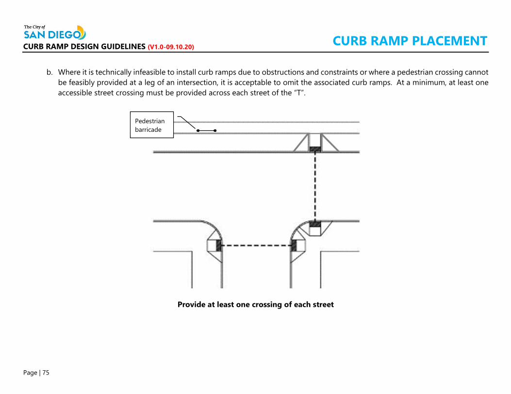
CURB RAMP DESIGN GUIDELINES (V1.0-09.10.20)
Page | 75
b. Where it is technically infeasible to install curb ramps due to obstructions and constraints or where a pedestrian crossing cannot be feasibly provided at a leg of an intersection, it is acceptable to omit the associated curb ramps. At a minimum, at least one accessible street crossing must be provided across each street of the “T”.
Provide at least one crossing of each street
Pedestrian barricade
CURB RAMP PLACEMENT
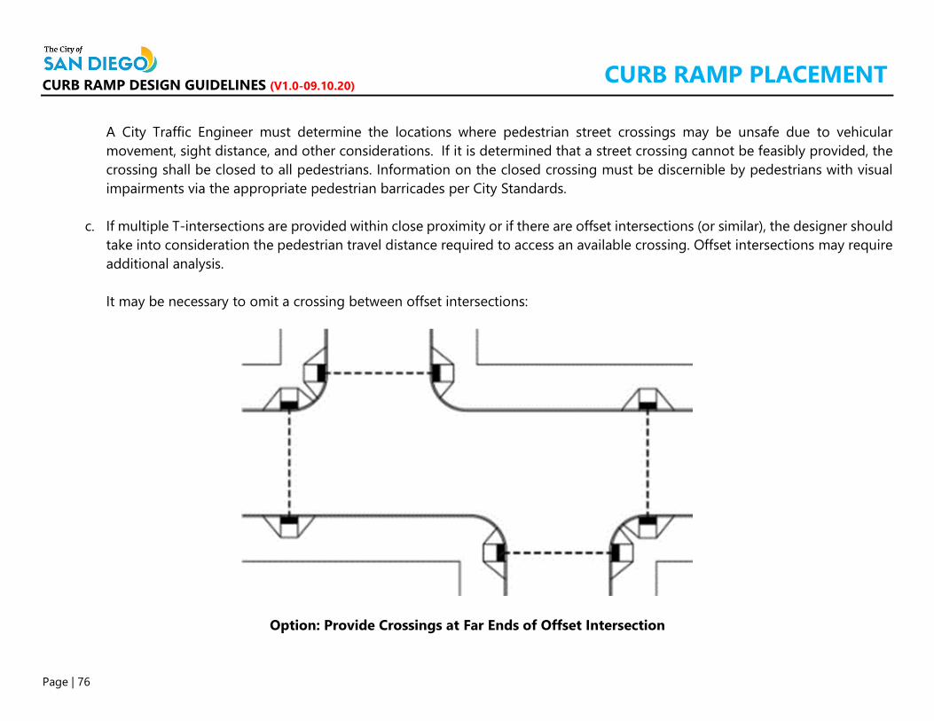
CURB RAMP DESIGN GUIDELINES (V1.0-09.10.20)
Page | 76
A City Traffic Engineer must determine the locations where pedestrian street crossings may be unsafe due to vehicular movement, sight distance, and other considerations. If it is determined that a street crossing cannot be feasibly provided, the crossing shall be closed to all pedestrians. Information on the closed crossing must be discernible by pedestrians with visual impairments via the appropriate pedestrian barricades per City Standards.
c. If multiple T-intersections are provided within close proximity or if there are offset intersections (or similar), the designer should take into consideration the pedestrian travel distance required to access an available crossing. Offset intersections may require additional analysis. It may be necessary to omit a crossing between offset intersections:
Option: Provide Crossings at Far Ends of Offset Intersection
CURB RAMP PLACEMENT

CURB RAMP DESIGN GUIDELINES (V1.0-09.10.20)
Page | 77
With the approval of a DCE, it is acceptable for offset T-intersections to share one crossing:
Option: Share One Crossing Between Offset Intersections
d. Notes:
The following conditions shall be prioritized for curb ramp improvements: o Any marked pedestrian crossings without curb ramps at existing intersections and midblock crossings with sidewalks. o Any existing marked pedestrian crossings without curb ramps at signalized intersections with no sidewalks. o Any existing marked or unmarked pedestrian crossings with no curb ramps at intersections with no sidewalks where
pedestrian trails are established. A Deviation from Standards Form must be submitted if curb ramp construction is not feasible at any location within an
intersection. Pedestrian barricades may be required if a diagonal curb ramp is used at a corner that serves a single pedestrian crossing. The placement of crosswalk markings shall be determined by the City’s Traffic Engineer.
CURB RAMP PLACEMENT

CURB RAMP DESIGN GUIDELINES (V1.0-09.10.20)
Page | 78
Turning slope at < 2.0%
Avoid asphalt wedges. Alterations are to the max. extent feasible. Depressed curb must be flush with roadway.
Transition sidewalk slope to match existing roadway grade.
17% Road
14% 11%
8% 5%
Cross slope within the curb ramp was adjusted to transition to existing slope on the sidewalk and roadway. The rate of change used was 3% per LF max. 14% at the 3-foot depth under the DWT 11% at 2 feet pass the DWT 8% at 1 foot 5% up to top edge of ramp
< 2.0%
EXAMPLES DIRECTIONAL CURB RAMP AT A SLOPED ROAD
14%
5’ x 5’ landing & transition

CURB RAMP DESIGN GUIDELINES (V1.0-09.10.20)
Page | 79
EXAMPLES CORNER WITH CONSTRAINTS
BEFORE:
AFTER:
Crossing was relocated
Relocated PPB Relocated PPB
Directional curb ramp

CURB RAMP DESIGN GUIDELINES (V1.0-09.10.20)
Page | 80
EXAMPLES CORNER WITH CONSTRAINTS
BEFORE:
AFTER:
Driveway Alley
Redesigned driveway and street pavement to accommodate the new alley curb ramp.

CURB RAMP DESIGN GUIDELINES (V1.0-09.10.20)
Page | 81
EXAMPLES CORNERS WITH CONSTRAINTS
BEFORE:
AFTER:
Type C2 curb ramp installed behind the storm drain inlet
Type C2 curb ramp installed behind the storm drain inlet

CURB RAMP DESIGN GUIDELINES (V1.0-09.10.20)
Page | 82
EXAMPLES CORNER WITH CONSTRAINTS
BEFORE:
AFTER:
New bulb-out
PPB
Improved access to the café. Pedestrian
barricade

CURB RAMP DESIGN GUIDELINES (V1.0-09.10.20)
Page | 83
EXAMPLES DUAL CURB RAMPS
Storm drain inlet

CURB RAMP DESIGN GUIDELINES (V1.0-09.10.20)
Page | 84
EXAMPLES DUAL CURB RAMPS
BEFORE:
AFTER:
PPB
Single diagonal curb ramp serving two pedestrian crossings
PPB’s
PPB

CURB RAMP DESIGN GUIDELINES (V1.0-09.10.20)
Page | 85
EXAMPLES SINGLE CURB RAMPS
A single Type A curb ramp with an extended ramp opening width may be used as an alternate design to accommodate the existing configuration of an intersection.

CURB RAMP DESIGN GUIDELINES (V1.0-09.10.20)
Page | 86
In certain situations when a half-flared curb ramp is used, a protective railing shall be installed if it is located within a pedestrian access route area.
EXAMPLES HALF-FLARED CURB RAMPS

CURB RAMP DESIGN GUIDELINES (V1.0-09.10.20)
Page | 87
Flare-less curb ramps are allowed on certain conditions and situations such as the one provided for an on-street accessible passenger loading zone.
EXAMPLES FLARE-LESS CURB RAMPS