cup loading
TRANSCRIPT
Cup Loading Tray for thePROTEAN® IEF Cell
For technical servicecall your local Bio-Rad office orin the U.S. call 1-800-4BIORAD(1-800-424-6723)On the Web at discover.bio-rad.com
Table of Contents
SSeeccttiioonn 11 IInnttrroodduuccttiioonn ........................................................................................................................................................................111.1 Overview..........................................................................................11.2 Introduction ....................................................................................11.3 Description ......................................................................................31.4 Specifications ..................................................................................4
SSeeccttiioonn 22 IInnssttrruuccttiioonnss ............................................................................................................................................................................442.1 General Overview ............................................................................42.2 IPG Strips Rehydration Solution Preparation and
Strip Rehydration ............................................................................52.3 Transfer and Placement of Rehydrated IPG Strips in the
Focusing Tray ..................................................................................52.4 Placement of Movable Electrodes....................................................62.5 Positioning Sample Loading Cups and Loading Sample..................62.6 Focusing Conditions ........................................................................82.7 After Focusing Run is Complete ......................................................9
SSeeccttiioonn 33 CClleeaanniinngg,, MMaaiinntteennaannccee,, aanndd CChheemmiiccaall CCoommppaattiibbiilliittyy ............................................11003.1 Focusing Tray ................................................................................103.2 Movable Electrode Assemblies ......................................................113.3 Cups ............................................................................................11
SSeeccttiioonn 44 GGeenneerraall GGuuiiddeelliinneess ffoorr SSaammppllee PPrreeppaarraattiioonn........................................................................1111SSeeccttiioonn 55 TTrroouubblleesshhoooottiinngg ........................................................................................................................................................1122SSeeccttiioonn 66 WWaarrrraannttyy ................................................................................................................................................................................1133
Section 1Introduction
1.1 Overview
The Cup Loading Tray for the PROTEAN IEF cell is designed for the optimal resolution and separation of proteins with isoelectric points (pI) at either extreme of the pH range. The CupLoading Tray can accommodate up to 12 IPG strips from 7 cm to 24 cm in length.
The Cup Loading Tray includes a tray base, a pair of movable electrode assemblies, and one bageach (120 count) of 100 and 150 µl sample cups. No modifications to the PROTEAN IEF cell areneeded for compatibility with the Cup Loading Tray.
The Cup Loading Tray offers the following benefits:
• Enhanced resolution and separation of proteins with pIs at extreme pH ranges
• Optimal focusing for users of ReadyStrip™ IPG strips pH 3-6, pH 7-10, and Micro-rangeReadyStrip IPG strips pH 6.3–8.3
• Tray runs up to 12 IPG strips per run for high throughput
• Tray accommodates 7 cm to 24 cm IPG strips with movable electrode assemblies
• Two sample cup sizes, 100 and 150 µl, are available to allow greater flexibility
• The Cup Loading Tray is compatible with all PROTEAN IEF cells, so no modification to existing PROTEAN IEF cell is necessary.
1.2 Introduction
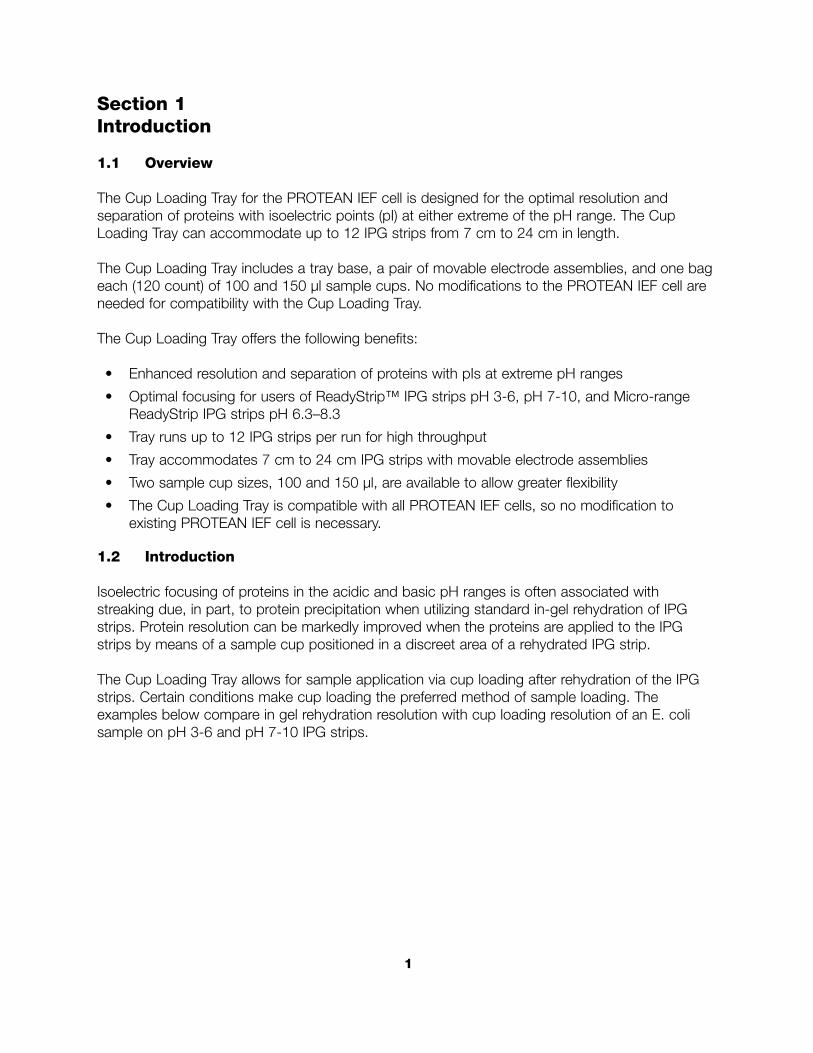
Isoelectric focusing of proteins in the acidic and basic pH ranges is often associated with streaking due, in part, to protein precipitation when utilizing standard in-gel rehydration of IPGstrips. Protein resolution can be markedly improved when the proteins are applied to the IPGstrips by means of a sample cup positioned in a discreet area of a rehydrated IPG strip.
The Cup Loading Tray allows for sample application via cup loading after rehydration of the IPGstrips. Certain conditions make cup loading the preferred method of sample loading. The examples below compare in gel rehydration resolution with cup loading resolution of an E. colisample on pH 3-6 and pH 7-10 IPG strips.
1
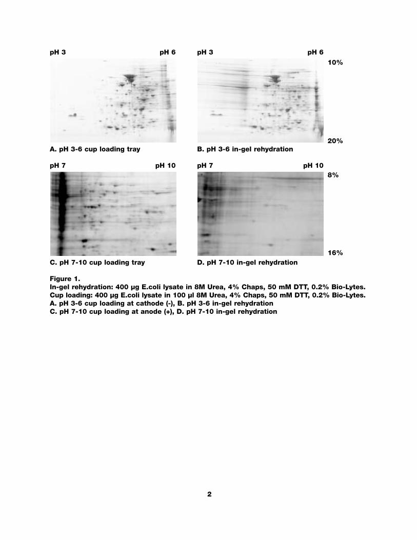
pH 3 pH 6 pH 3 pH 6
A. pH 3-6 cup loading tray B. pH 3-6 in-gel rehydration
pH 7 pH 10 pH 7 pH 10
C. pH 7-10 cup loading tray D. pH 7-10 in-gel rehydration
Figure 1.In-gel rehydration: 400 µg E.coli lysate in 8M Urea, 4% Chaps, 50 mM DTT, 0.2% Bio-Lytes.Cup loading: 400 µg E.coli lysate in 100 µl 8M Urea, 4% Chaps, 50 mM DTT, 0.2% Bio-Lytes.A. pH 3-6 cup loading at cathode (-), B. pH 3-6 in-gel rehydrationC. pH 7-10 cup loading at anode (+), D. pH 7-10 in-gel rehydration
2
10%
20%
8%
16%
1.3 Description
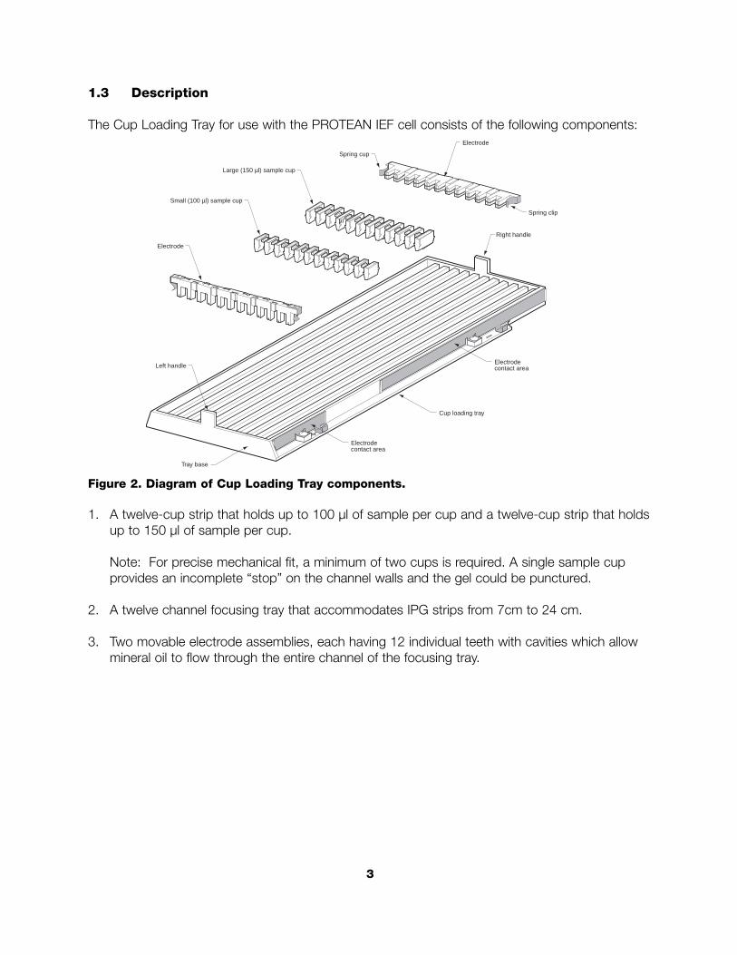
The Cup Loading Tray for use with the PROTEAN IEF cell consists of the following components:
Figure 2. Diagram of Cup Loading Tray components.
1. A twelve-cup strip that holds up to 100 µl of sample per cup and a twelve-cup strip that holdsup to 150 µl of sample per cup.
Note: For precise mechanical fit, a minimum of two cups is required. A single sample cupprovides an incomplete “stop” on the channel walls and the gel could be punctured.
2. A twelve channel focusing tray that accommodates IPG strips from 7cm to 24 cm.
3. Two movable electrode assemblies, each having 12 individual teeth with cavities which allowmineral oil to flow through the entire channel of the focusing tray.
Electrode
Left handle
Tray base
Small (100 µl) sample cup
Electrode
Spring cup
Electrodecontact area
Electrodecontact area
Cup loading tray
Spring clip
Right handle
µl
Large (150 µl) sample cup
3
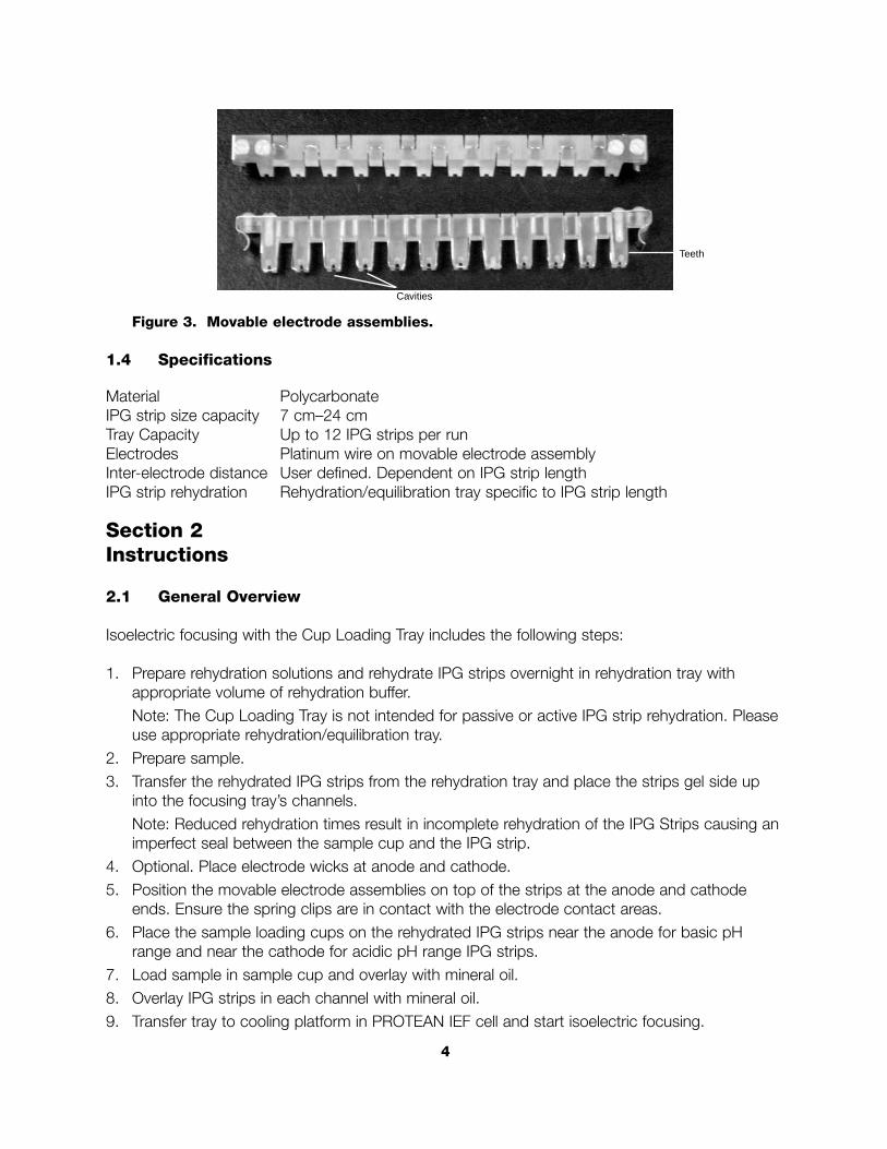
Figure 3. Movable electrode assemblies.
1.4 Specifications
Material PolycarbonateIPG strip size capacity 7 cm–24 cmTray Capacity Up to 12 IPG strips per runElectrodes Platinum wire on movable electrode assemblyInter-electrode distance User defined. Dependent on IPG strip lengthIPG strip rehydration Rehydration/equilibration tray specific to IPG strip length
Section 2Instructions
2.1 General Overview
Isoelectric focusing with the Cup Loading Tray includes the following steps:
1. Prepare rehydration solutions and rehydrate IPG strips overnight in rehydration tray withappropriate volume of rehydration buffer.Note: The Cup Loading Tray is not intended for passive or active IPG strip rehydration. Pleaseuse appropriate rehydration/equilibration tray.
2. Prepare sample.3. Transfer the rehydrated IPG strips from the rehydration tray and place the strips gel side up
into the focusing tray’s channels.Note: Reduced rehydration times result in incomplete rehydration of the IPG Strips causing animperfect seal between the sample cup and the IPG strip.
4. Optional. Place electrode wicks at anode and cathode.5. Position the movable electrode assemblies on top of the strips at the anode and cathode
ends. Ensure the spring clips are in contact with the electrode contact areas.6. Place the sample loading cups on the rehydrated IPG strips near the anode for basic pH
range and near the cathode for acidic pH range IPG strips.7. Load sample in sample cup and overlay with mineral oil. 8. Overlay IPG strips in each channel with mineral oil.9. Transfer tray to cooling platform in PROTEAN IEF cell and start isoelectric focusing.
4
Cavities
Teeth
2.2 IPG Strip Rehydration Solution Preparation and Strip Rehydration
1. Prepare rehydration sample buffer and rehydrate IPG strips just prior to sample cup-loadingand isoelectric focusing. Add the indicated volume of rehydration buffer to each of therequired channels in the rehydration tray to rehydrate to 0.53 mm thickness.
Note: Rehydration to 0.53 mm thickness ensures a complete seal between the cup and theIPG strip. The following volumes are 10% greater than those recommended in the ReadyStripIPG Strip instruction manual.
IPG Length 7 cm 11 cm 17 cm 18 cm 24 cm
Rehydration volume for 135 µl 200 µl 330 µl 345 µl 450 µlcuploading
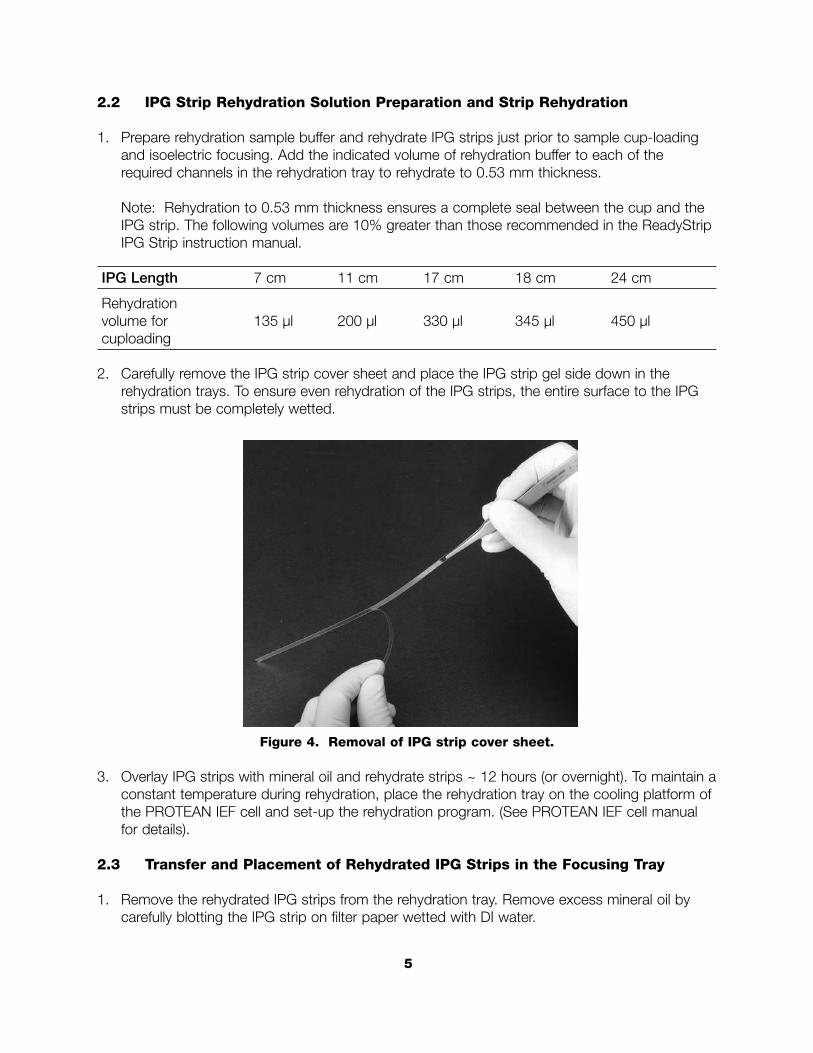
2. Carefully remove the IPG strip cover sheet and place the IPG strip gel side down in the rehydration trays. To ensure even rehydration of the IPG strips, the entire surface to the IPGstrips must be completely wetted.
Figure 4. Removal of IPG strip cover sheet.
3. Overlay IPG strips with mineral oil and rehydrate strips ~ 12 hours (or overnight). To maintain aconstant temperature during rehydration, place the rehydration tray on the cooling platform ofthe PROTEAN IEF cell and set-up the rehydration program. (See PROTEAN IEF cell manualfor details).
2.3 Transfer and Placement of Rehydrated IPG Strips in the Focusing Tray
1. Remove the rehydrated IPG strips from the rehydration tray. Remove excess mineral oil bycarefully blotting the IPG strip on filter paper wetted with DI water.
5
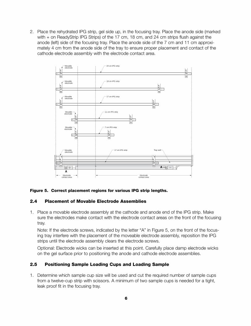
2. Place the rehydrated IPG strip, gel side up, in the focusing tray. Place the anode side (markedwith + on ReadyStrip IPG Strips) of the 17 cm, 18 cm, and 24 cm strips flush against theanode (left) side of the focusing tray. Place the anode side of the 7 cm and 11 cm approxi-mately 4 cm from the anode side of the tray to ensure proper placement and contact of thecathode electrode assembly with the electrode contact area.
Figure 5. Correct placement regions for various IPG strip lengths.
2.4 Placement of Movable Electrode Assemblies
1. Place a movable electrode assembly at the cathode and anode end of the IPG strip. Makesure the electrodes make contact with the electrode contact areas on the front of the focusingtray.
Note: If the electrode screws, indicated by the letter “A” in Figure 5, on the front of the focus-ing tray interfere with the placement of the moveable electrode assembly, reposition the IPGstrips until the electrode assembly clears the electrode screws.
Optional: Electrode wicks can be inserted at this point. Carefully place damp electrode wickson the gel surface prior to positioning the anode and cathode electrode assemblies.
2.5 Positioning Sample Loading Cups and Loading Sample
1. Determine which sample cup size will be used and cut the required number of sample cupsfrom a twelve-cup strip with scissors. A minimum of two sample cups is needed for a tight,leak proof fit in the focusing tray.
Electrodecontact area
-
Electrodecontact area
Movableelectrode
24 cm IPG strip
-
Movableelectrode
18 cm IPG strip
-
-
Movableelectrode
17 cm IPG strip
-
Movableelectrode
11 cm IPG strip
-
Movableelectrode
7 cm IPG strip
17 cm IPG strip Tray wellMovableelectrode
6
A
A
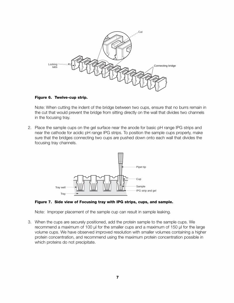
Figure 6. Twelve-cup strip.
Note: When cutting the indent of the bridge between two cups, ensure that no burrs remain inthe cut that would prevent the bridge from sitting directly on the wall that divides two channelsin the focusing tray.
2. Place the sample cups on the gel surface near the anode for basic pH range IPG strips andnear the cathode for acidic pH range IPG strips. To position the sample cups properly, makesure that the bridges connecting two cups are pushed down onto each wall that divides thefocusing tray channels.
Figure 7. Side view of Focusing tray with IPG strips, cups, and sample.
Note: Improper placement of the sample cup can result in sample leaking.
3. When the cups are securely positioned, add the protein sample to the sample cups. We recommend a maximum of 100 µl for the smaller cups and a maximum of 150 µl for the largevolume cups. We have observed improved resolution with smaller volumes containing a higherprotein concentration, and recommend using the maximum protein concentration possible inwhich proteins do not precipitate.
Tray
Tray wellIPG strip and gel
Cup
Pipet tip
Sample
Lockingtabs
Cut
7
Connecting bridge
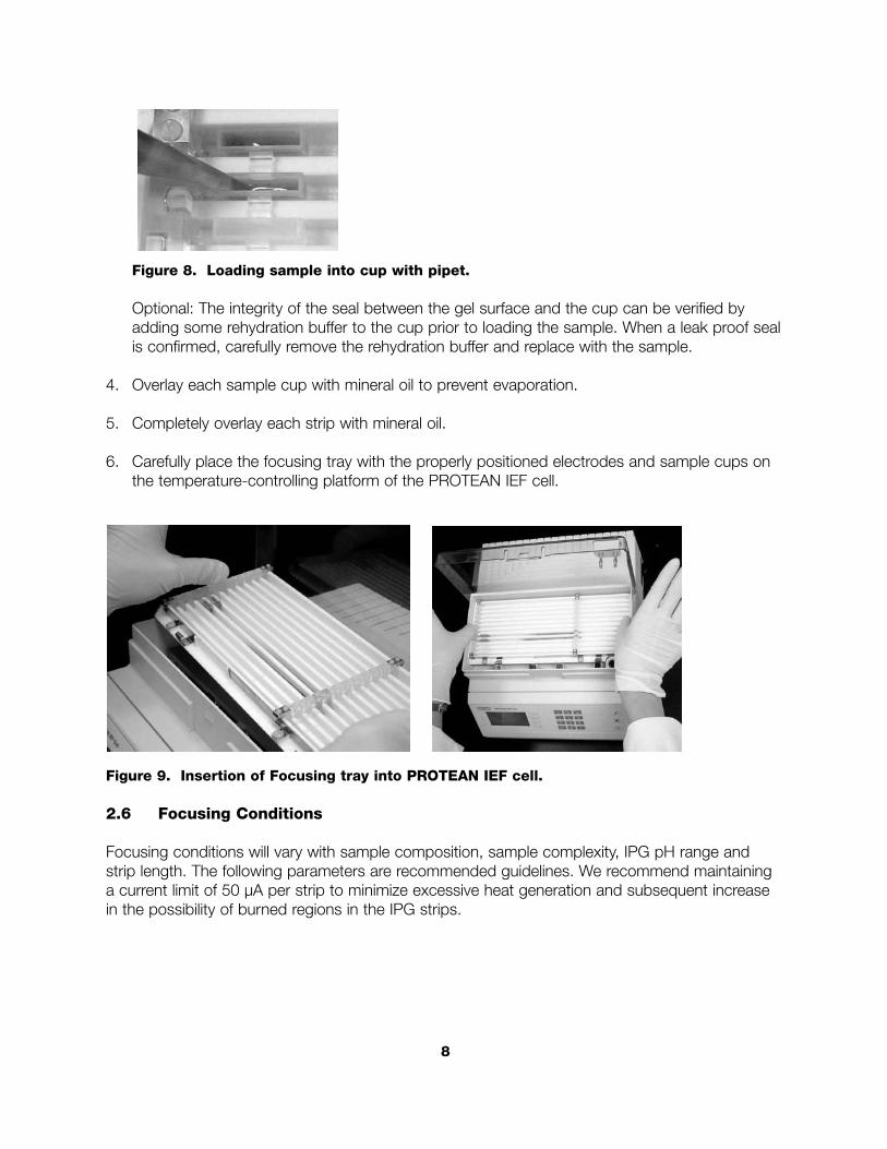
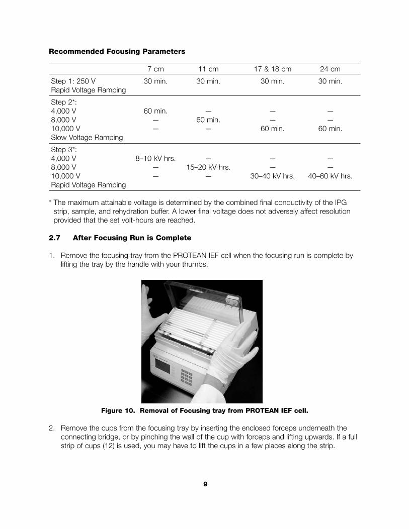
Figure 8. Loading sample into cup with pipet.
Optional: The integrity of the seal between the gel surface and the cup can be verified byadding some rehydration buffer to the cup prior to loading the sample. When a leak proof sealis confirmed, carefully remove the rehydration buffer and replace with the sample.
4. Overlay each sample cup with mineral oil to prevent evaporation.
5. Completely overlay each strip with mineral oil.
6. Carefully place the focusing tray with the properly positioned electrodes and sample cups onthe temperature-controlling platform of the PROTEAN IEF cell.
Figure 9. Insertion of Focusing tray into PROTEAN IEF cell.
2.6 Focusing Conditions
Focusing conditions will vary with sample composition, sample complexity, IPG pH range andstrip length. The following parameters are recommended guidelines. We recommend maintaininga current limit of 50 µA per strip to minimize excessive heat generation and subsequent increasein the possibility of burned regions in the IPG strips.
8
Recommended Focusing Parameters
7 cm 11 cm 17 & 18 cm 24 cm
Step 1: 250 V 30 min. 30 min. 30 min. 30 min.Rapid Voltage Ramping
Step 2*:4,000 V 60 min. — — —8,000 V — 60 min. — —10,000 V — — 60 min. 60 min.Slow Voltage Ramping
Step 3*:4,000 V 8–10 kV hrs. — — —8,000 V — 15–20 kV hrs. — —10,000 V — — 30–40 kV hrs. 40–60 kV hrs.Rapid Voltage Ramping
* The maximum attainable voltage is determined by the combined final conductivity of the IPGstrip, sample, and rehydration buffer. A lower final voltage does not adversely affect resolutionprovided that the set volt-hours are reached.
2.7 After Focusing Run is Complete
1. Remove the focusing tray from the PROTEAN IEF cell when the focusing run is complete bylifting the tray by the handle with your thumbs.
Figure 10. Removal of Focusing tray from PROTEAN IEF cell.
2. Remove the cups from the focusing tray by inserting the enclosed forceps underneath theconnecting bridge, or by pinching the wall of the cup with forceps and lifting upwards. If a fullstrip of cups (12) is used, you may have to lift the cups in a few places along the strip.
9
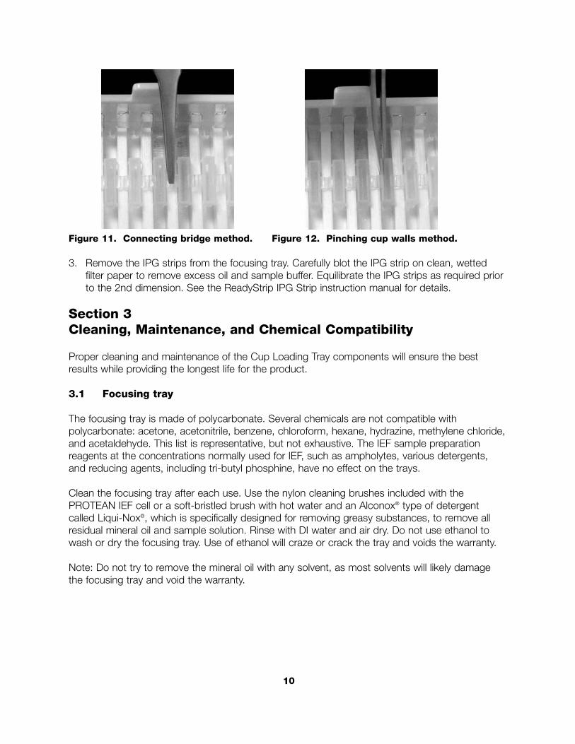
Figure 11. Connecting bridge method. Figure 12. Pinching cup walls method.
3. Remove the IPG strips from the focusing tray. Carefully blot the IPG strip on clean, wetted filter paper to remove excess oil and sample buffer. Equilibrate the IPG strips as required priorto the 2nd dimension. See the ReadyStrip IPG Strip instruction manual for details.
Section 3Cleaning, Maintenance, and Chemical Compatibility
Proper cleaning and maintenance of the Cup Loading Tray components will ensure the bestresults while providing the longest life for the product.
3.1 Focusing tray
The focusing tray is made of polycarbonate. Several chemicals are not compatible with polycarbonate: acetone, acetonitrile, benzene, chloroform, hexane, hydrazine, methylene chloride,and acetaldehyde. This list is representative, but not exhaustive. The IEF sample preparationreagents at the concentrations normally used for IEF, such as ampholytes, various detergents,and reducing agents, including tri-butyl phosphine, have no effect on the trays.
Clean the focusing tray after each use. Use the nylon cleaning brushes included with the PROTEAN IEF cell or a soft-bristled brush with hot water and an Alconox® type of detergentcalled Liqui-Nox®, which is specifically designed for removing greasy substances, to remove allresidual mineral oil and sample solution. Rinse with DI water and air dry. Do not use ethanol towash or dry the focusing tray. Use of ethanol will craze or crack the tray and voids the warranty.
Note: Do not try to remove the mineral oil with any solvent, as most solvents will likely damagethe focusing tray and void the warranty.
10
3.2 Movable Electrode Assemblies
Use the nylon cleaning brushes included with the PROTEAN IEF cell or a soft-bristled brush toclean the movable electrode assemblies with hot water and Liqui-Nox. Take care to ensure theplatinum wire does not break. Rinse with DI water and air dry. Do not use ethanol to wash or drythe movable electrode assemblies.
3.3 Cups
The Cup Loading Tray's cups are designed to be disposable and are not recommended forreuse.
*Alconox and Liqui-Nox are registered trademarks of Alconox.
Section 4General Guidelines for Sample Preparation
See ReadyStrip IPG Strip instruction manual for general guidelines for sample preparation. Foradditional information on sample preparation, go to www.ProteomeWorksSystem.com
11
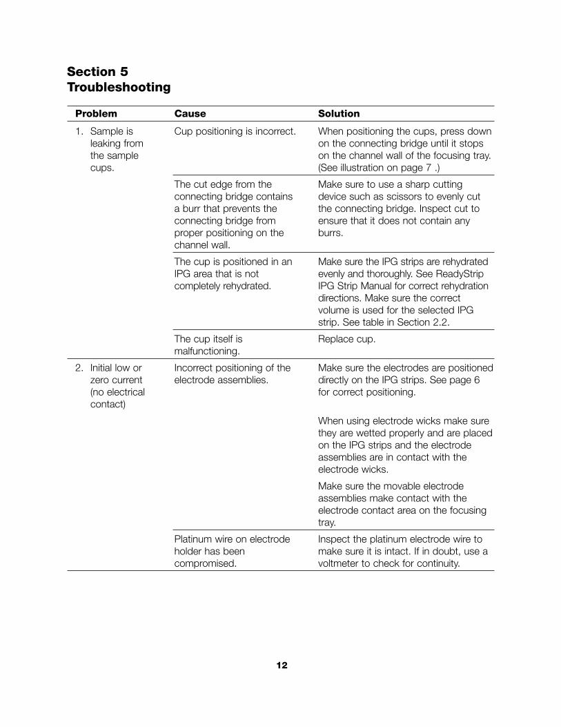
Section 5Troubleshooting
Problem Cause Solution
1. Sample is Cup positioning is incorrect. When positioning the cups, press downleaking from on the connecting bridge until it stops the sample on the channel wall of the focusing tray.cups. (See illustration on page 7 .)
The cut edge from the Make sure to use a sharp cutting connecting bridge contains device such as scissors to evenly cut a burr that prevents the the connecting bridge. Inspect cut to connecting bridge from ensure that it does not contain any proper positioning on the burrs. channel wall.
The cup is positioned in an Make sure the IPG strips are rehydrated IPG area that is not evenly and thoroughly. See ReadyStrip completely rehydrated. IPG Strip Manual for correct rehydration
directions. Make sure the correct volume is used for the selected IPGstrip. See table in Section 2.2.
The cup itself is Replace cup.malfunctioning.
2. Initial low or Incorrect positioning of the Make sure the electrodes are positioned zero current electrode assemblies. directly on the IPG strips. See page 6(no electrical for correct positioning.contact)
When using electrode wicks make surethey are wetted properly and are placedon the IPG strips and the electrodeassemblies are in contact with the electrode wicks.
Make sure the movable electrodeassemblies make contact with the electrode contact area on the focusingtray.
Platinum wire on electrode Inspect the platinum electrode wire to holder has been make sure it is intact. If in doubt, use a compromised. voltmeter to check for continuity.
12
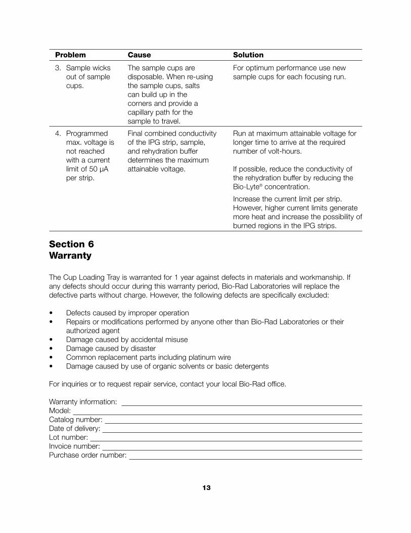
Problem Cause Solution
3. Sample wicks The sample cups are For optimum performance use new out of sample disposable. When re-using sample cups for each focusing run. cups. the sample cups, salts
can build up in the corners and provide a capillary path for the sample to travel.
4. Programmed Final combined conductivity Run at maximum attainable voltage formax. voltage is of the IPG strip, sample, longer time to arrive at the required not reached and rehydration buffer number of volt-hours.with a current determines the maximum limit of 50 µA attainable voltage. If possible, reduce the conductivity of per strip. the rehydration buffer by reducing the
Bio-Lyte® concentration.
Increase the current limit per strip.However, higher current limits generatemore heat and increase the possibility ofburned regions in the IPG strips.
Section 6Warranty
The Cup Loading Tray is warranted for 1 year against defects in materials and workmanship. Ifany defects should occur during this warranty period, Bio-Rad Laboratories will replace the defective parts without charge. However, the following defects are specifically excluded:
• Defects caused by improper operation• Repairs or modifications performed by anyone other than Bio-Rad Laboratories or their
authorized agent• Damage caused by accidental misuse• Damage caused by disaster• Common replacement parts including platinum wire• Damage caused by use of organic solvents or basic detergents
For inquiries or to request repair service, contact your local Bio-Rad office.
Warranty information:Model:Catalog number:Date of delivery:Lot number:Invoice number:Purchase order number:
13
4006216 Rev A