cummins isl-g - american public transportation association · 2020-01-07 · • cummins quikserve...
TRANSCRIPT
Cummins ISL-GWebinar
Deputy Chief Engineering Officer Southeastern Pennsylvania Transportation Authority (SEPTA)Philadelphia, PA
Jerry Guaracino
Moderator


Obed MejiaSenior Bus Equipment Maintenance InstructorLos Angeles Metropolitan Transportation Authority Los Angeles, CA
Victoria ChesneyMaintenance SupervisorOmnitransSan Bernardino, CA
Presenters

Objectives
Participants on today’s webinar will learn how to:• Identify Maintenance Procedures • Examine components to meet specifications• Perform maintenance practices to OEM specifications

Related APTA Standards
• APTA BTS-BMT-RP-008-16: Training Syllabus to Instruct Bus Technicians on EPA Emissions Standards and Treatment Technologies
For additional resources visit: http://www.apta.com/resources/standards/bus/Pages/default.aspx

Fleet Facts
Metro• 2400+ Buses in service
• 2300 ISL-G• 100 L Gas Plus
• Revenue Miles ≈ 90 million per year
Omnitrans• 187 Fixed Route Coaches• 22 Cummins 8.3 C+ • 43 8.1 John Deere HFN04 • 122 8.9 Cummins ISL G• Service area of 456 sq. miles with
just over 9 million miles run per year.

Operating Parameters• Maximum Horsepower 320 HP • Peak Torque 1000 LB-FT • Governed Speed 2200 RPM• Engine Displacement 540 CU IN 8.9
LITERS• spark-ignited, in-line 6-cylinder,
turbocharged, CAC• Fuel Type CNG/LNG/RNG Methane
number75 or greater• Aftertreatment Three-Way Catalyst (TW

Engine Management System• The control system for the ISL-G engine
is a closed loop control system. The electronic control module controls the throttle plate and fuel control valve to provide the correct fueling and spark timing.
• The ISL-G engine through the years has been built with several potential sensor configurations and terminology variances.
• Ensure that you are using the latest software version to correctly interact with control system.

Control System Components

Control System Components

Ignition System Capacitive discharge system. • The ICM (Ignition Control
Module) steps 12V input and steps up to 250-300V to the primary side of the coil.

CNG Fuel Flow - Sample

EGR System• The EGR system is responsible for re-
circulating metered exhaust gas back into the combustion chamber.
• This is done to cool down the chamber temperature by introducing inert gas.
• Nitric Oxides emissions are formed when engine chamber temperatures rise above 2500° F. Keeping the chamber cool reduces NOx emission.
• System Components: EGR valve, cooler, flow and temperature sensors.
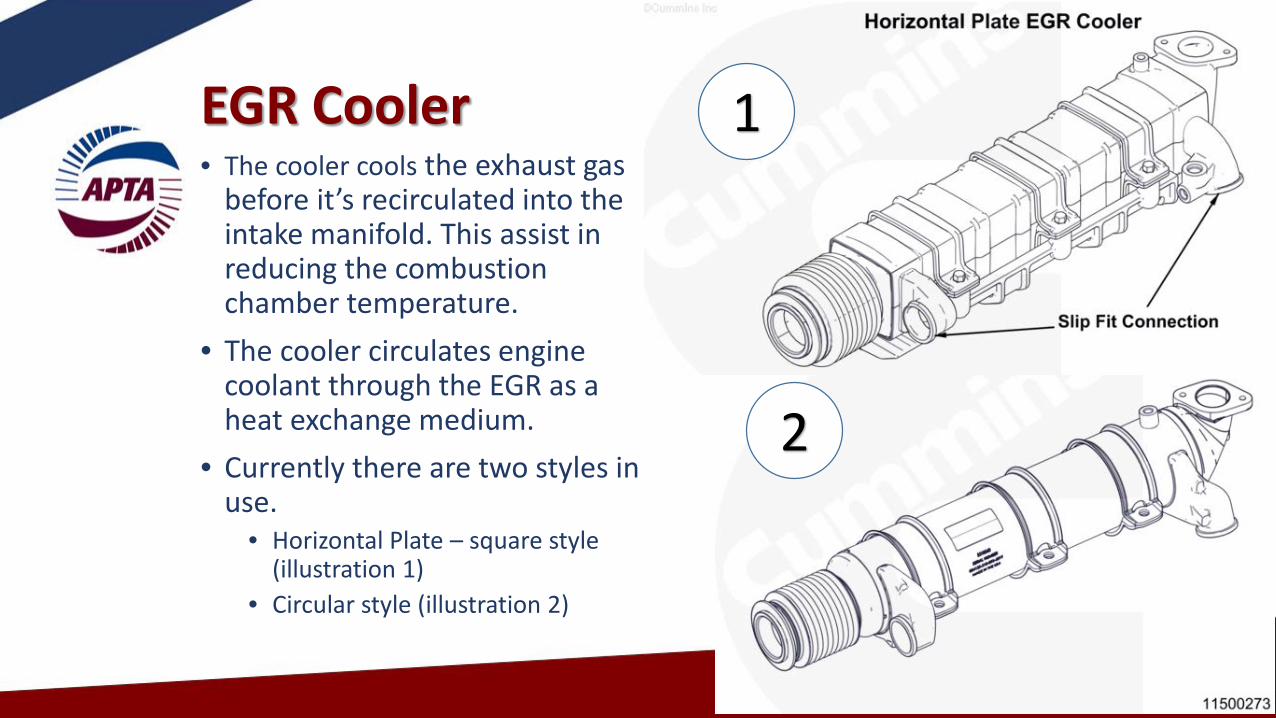
EGR Cooler • The cooler cools the exhaust gas
before it’s recirculated into the intake manifold. This assist in reducing the combustion chamber temperature.
• The cooler circulates engine coolant through the EGR as a heat exchange medium.
• Currently there are two styles in use.
• Horizontal Plate – square style (illustration 1)
• Circular style (illustration 2)
1
2

Maintenance Procedures

Spark Plug R&R ProcedureRemoval:
• Do not wiggle coil brackets when removing coils – remove straight up
• Remove spark plug with a magnetic socket• Blow-Out Spark Plug cavity

Spark Plug R&R ProcedureInstallation:• Check Plug Gap – do not adjust/do
not install if out of gap• Prior to installation spark plug must
be cleaned with alcohol pad or swab. Dirt, oil, and fingerprints reduce the seal strength between the spark plug boot and the porcelain causing reduced spark plug life.
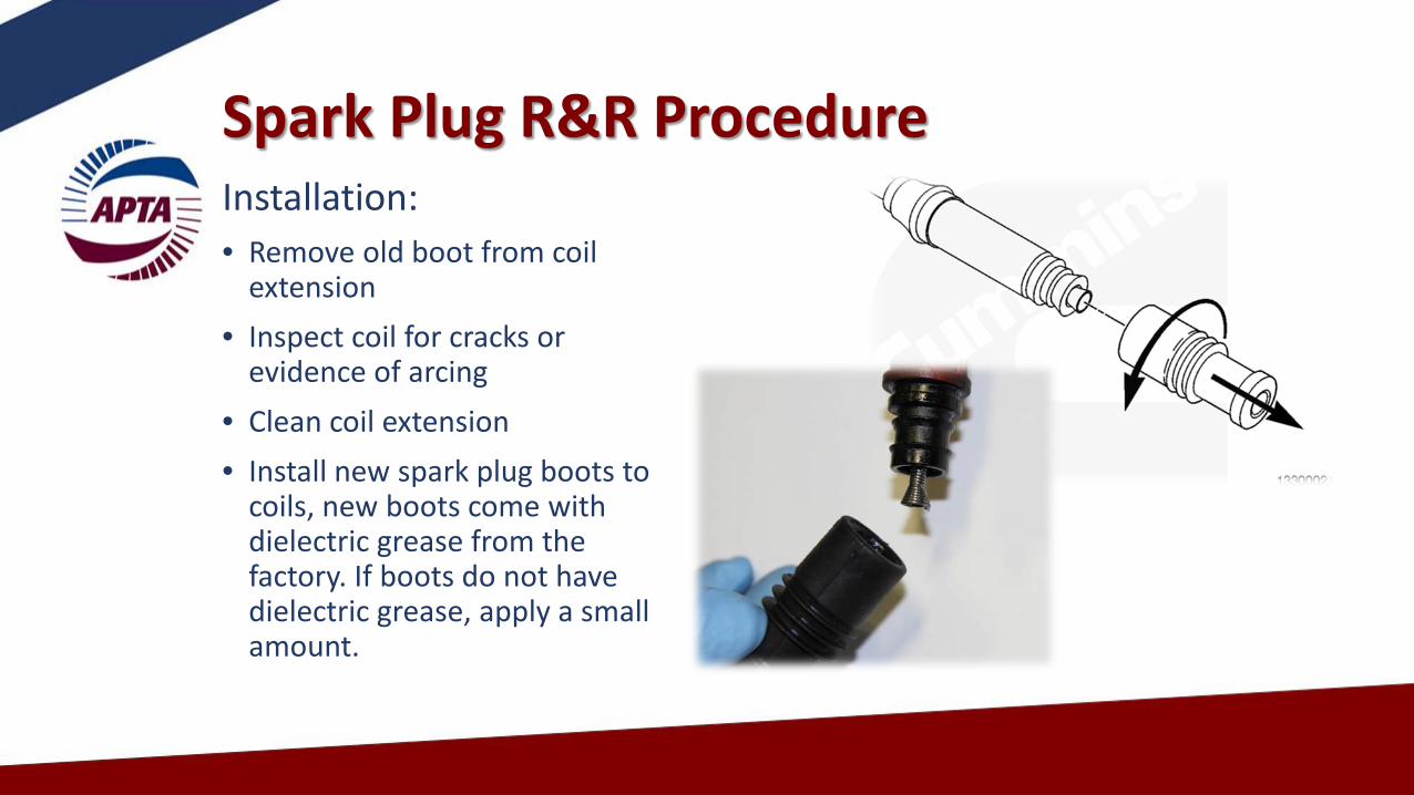
Spark Plug R&R ProcedureInstallation:• Remove old boot from coil
extension• Inspect coil for cracks or
evidence of arcing• Clean coil extension• Install new spark plug boots to
coils, new boots come with dielectric grease from the factory. If boots do not have dielectric grease, apply a small amount.

Spark Plug R&R ProcedureInstallation:• Install new spark plugs using clean
magnetic spark plug socket.• Torque spark plug to 28 ft-lb (35 Nm).
• Failure to torque spark plugs will result in engine misfire and premature spark plug failure.
• Proper torque aids in heat dissipation

Acceptable Spark Reuse - Cummins
Consult Cummins Quikserve for latest TSB’s

Not-Acceptable Spark Reuse - Cummins
Consult Cummins Quikserve for latest TSB’s
Valve Adjustment ProceduresGeneral Knowledge: valve adjustments are a critical part of the preventive maintenance and the bus repair process. During the procedure; keep in mind:• Engine should be at 140⁰ F or less.• Check valve height – valve may recess into head causing performance
complaints• Check the rocker shafts for wear – this may cause the rocker to bind

Valve Adjustment Procedure Overlap Method:1. Rotate engine until valve overlap is reached
on cylinder #6. Valve overlap is when both the intake and exhaust valves are opened at the same time. You will notice that as the exhaust valve is closing the intake valve starts to open. Valve overlap occurs for about 15° of crankshaft rotation.
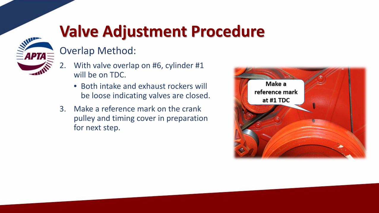
Valve Adjustment ProcedureOverlap Method:2. With valve overlap on #6, cylinder #1
will be on TDC.• Both intake and exhaust rockers will
be loose indicating valves are closed.3. Make a reference mark on the crank
pulley and timing cover in preparation for next step.

Valve Adjustment ProcedureOverlap Method:4. Adjust valves as shown below.

Valve Adjustment ProcedureAdjustment Specs:Intake: .014 in. Exhaust: .030 in. During the adjustment, keep in mind to:• Keep medium drag on the feeler gauge to
complete adjustment.• Tight valves will cause performance issues. • Loose valves will cause noise and
performance issues.• Recheck lash after tightening adjuster screw.

Valve Adjustment ProcedureOverlap Method:6. After adjusting valves on
valve overlap on cylinder #6, rotate the engine a full revolution 360°. Align the previously made reference marks. Cylinder #1 is now in overlap and cylinder #6 at Top Dead Center (TDC).
7. Adjust valves 2E 3l, 4E,5l, 6l and 6E.

Valve Adjustment Procedure –Rocker Shafts – it is recommended to perform a rocker assembly inspection.(requires removal of rocker assemblies)
• Remove and mark the pedestals and rocker lever assemblies one at a time. Inspect for cracks and excessive wear on the shafts. Check for scoring and or binding. – replace assembly if found. The rocker arm should move freely on the rocker shaft.
• Inspect the rocker lever pedestal and rocker lever shaft for cracks.

Valve Adjustment ProcedureReceded Valves:A- Inspect the valve stems for height variations. Valves that are sticking out too far indicate the valve has receded into cylinder head.B- Using a straight edge, look for the valve stems to be NO more than 3/16” higher than others. If valves are found to be high; replace the cylinder head. Recessed valves cause performance issues that may include low power and a CEL.
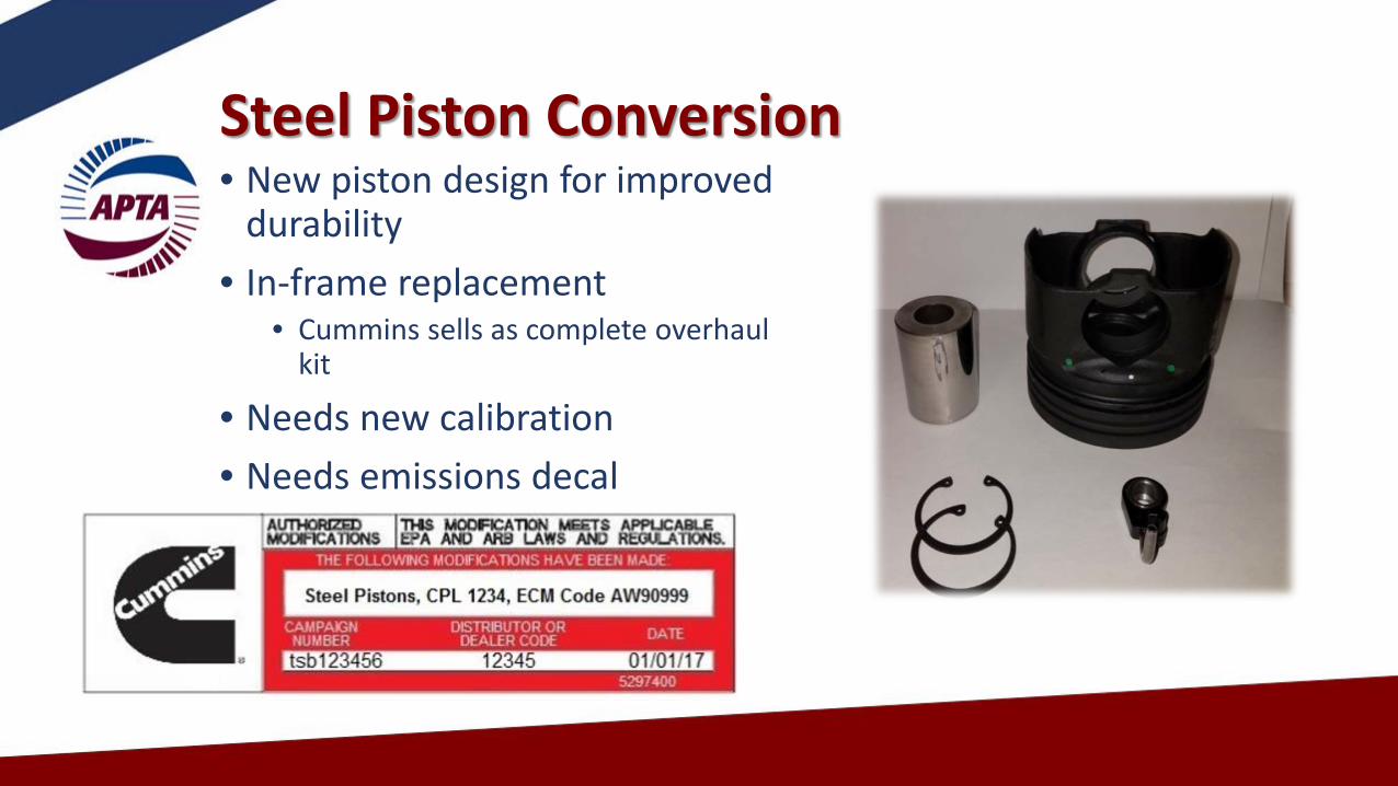
Steel Piston Conversion• New piston design for improved
durability• In-frame replacement
• Cummins sells as complete overhaul kit
• Needs new calibration• Needs emissions decal

EGR Cooler Carbon• New EGR Cooler longevity is
now showing the typical carbon buildup of EGR coolers
• Causes trouble codes for EGR cooler temperature
• Cummins recommends cleaning the carbon buildup

Maintenance Concerns
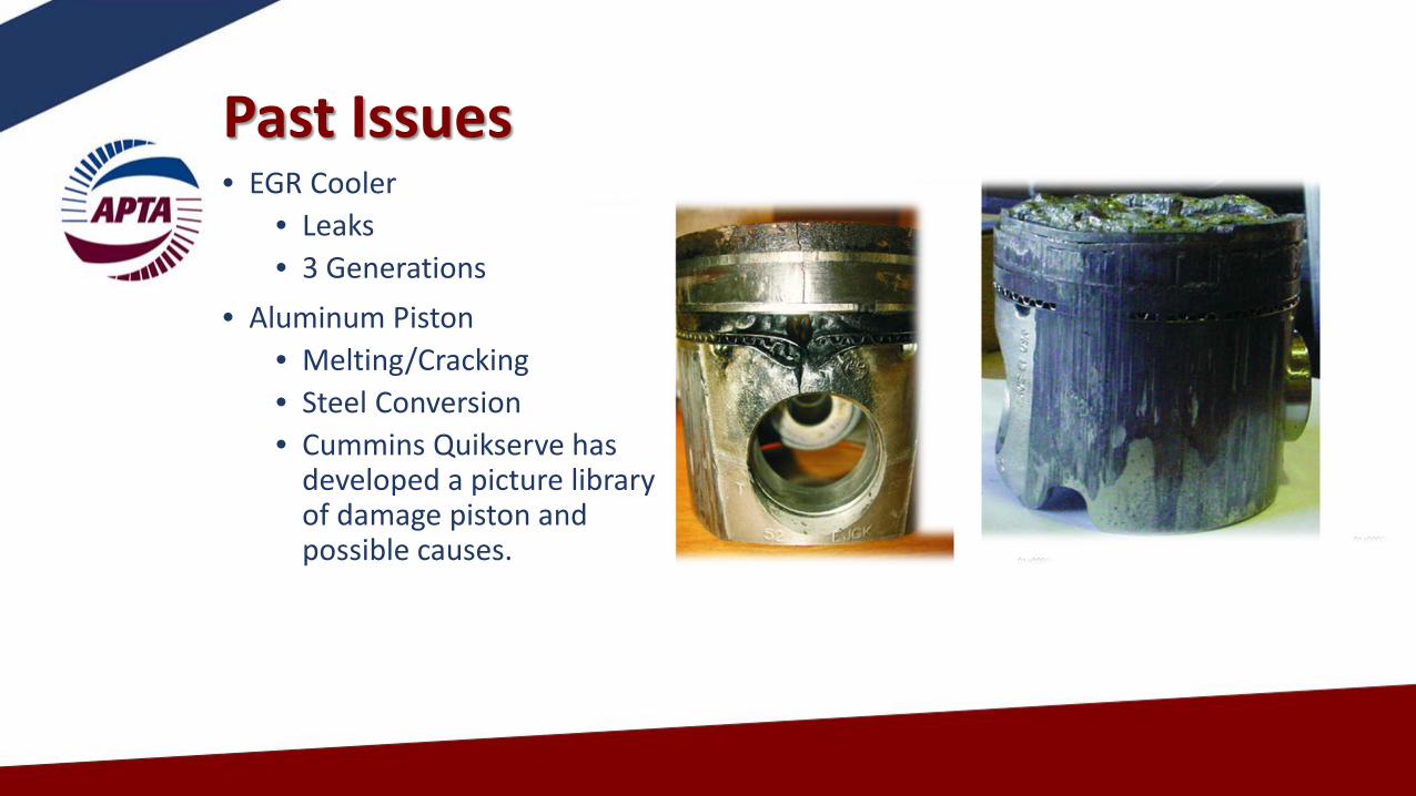
Past Issues• EGR Cooler
• Leaks• 3 Generations
• Aluminum Piston• Melting/Cracking• Steel Conversion• Cummins Quikserve has
developed a picture library of damage piston and possible causes.

Past Issues
• Ignition Control Module• High failure rate – caused misfire codes• Susceptible to voltage and ground
fluctuations
• Collateral Damage• Turbo, spark plugs, 02 sensor, catalyst
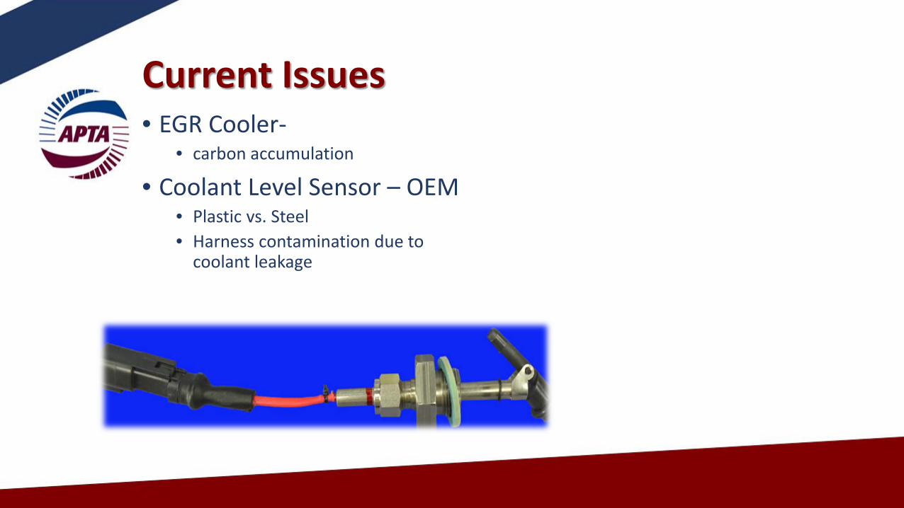
Current Issues • EGR Cooler-
• carbon accumulation
• Coolant Level Sensor – OEM• Plastic vs. Steel• Harness contamination due to
coolant leakage

Training
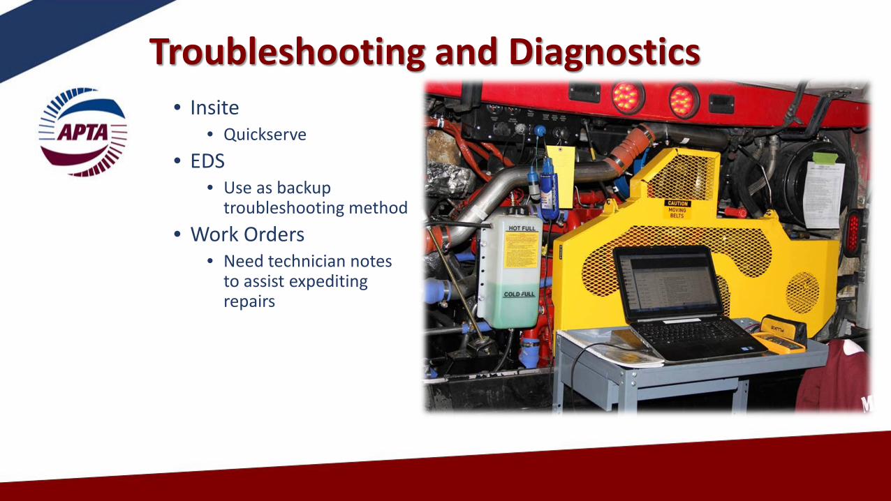
Troubleshooting and Diagnostics• Insite
• Quickserve• EDS
• Use as backup troubleshooting method
• Work Orders• Need technician notes
to assist expediting repairs
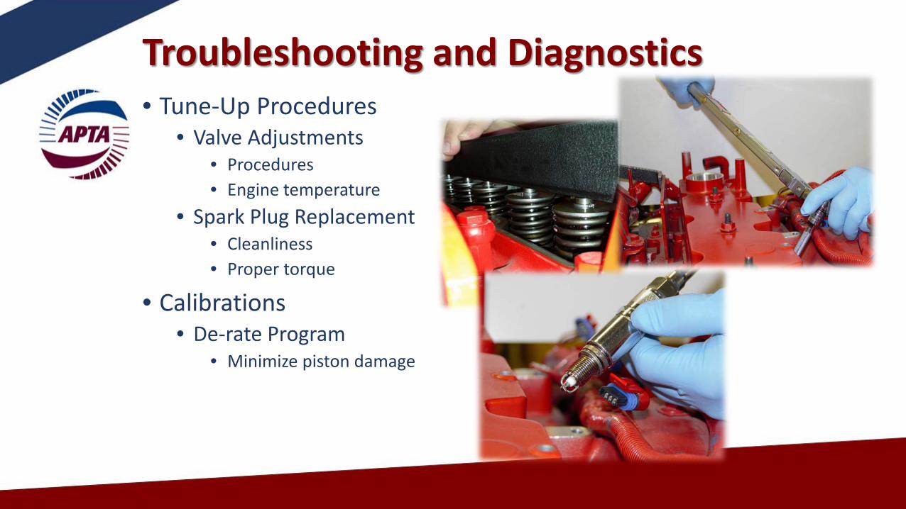
Troubleshooting and Diagnostics• Tune-Up Procedures
• Valve Adjustments• Procedures• Engine temperature
• Spark Plug Replacement• Cleanliness• Proper torque
• Calibrations • De-rate Program
• Minimize piston damage

Summary

The Future of CNG• ISL-G Near Zero Engine = L9N
• Omnitrans will be retrofitting its older coaches • All new bus buys will have the near zero installed
• LA Metro current bus orders will have near zero installed• 295 El Dorado Buses
• LA Metro currently installing as replacement engine during midlife• 400+ engines on procurement
• LA Metro moving to 100% Electric Vehicle Fleet• The Goal is 2030 • Contracts for 100 Electric buses have been awarded

42
Any Questions?Please e-mail the questions to
The APTA Brake and Chassis Work Group and the APTA Bus Standards Committee would like to thank you for joining our Webinar.
Pictures, drawings and technical information courtesy of MAN, ZF, Meritor, Knorr-Bremse, Bendix, MGM Brakes, LA Metro, Omnitrans, MBTA, Custom Training Aids, Link Engineering, and other members of the APTA Brake and Chassis Work Group