cuatro router pod - netdevgroup.com · cuatro router pod ... and mouse of the vmware virtual...
TRANSCRIPT
Cuatro Router Pod
Planning and Installation Guide
For Cisco Networking Academy® CCNA & CCNP Curriculum
Document Version: 2007-01-22
Copyright © 2007, Network Development Group, Inc. www.netdevgroup.com Network Development Group grants permission for Cisco Networking Academies to make copies and distribute this document to Academy students and instructors, provided that the document content is not modified. NETLAB Academy Edition and NETLAB+ are registered trademarks of Network Development Group, Inc. Cisco, IOS, Cisco IOS, Networking Academy, CCNA, CCNP, and PIX are registered trademarks of Cisco Systems, Inc.
NETLABAE Cuatro Router Pod www.netdevgroup.com
1/22/2007 Page 2 of 36
1 Introduction ................................................................................................................. 3 1.1 Deviations............................................................................................................. 4
1.2 Remote PC Support .............................................................................................. 4 1.3 Dynamic Topologies ............................................................................................ 4
2 Lab Device Requirements ........................................................................................... 5 2.1 Routers R1, R2, R3 and R4 .................................................................................. 5 2.2 PCs and Servers .................................................................................................... 6
3 Control Device Requirements ..................................................................................... 7 3.1 Control Switch Overview ..................................................................................... 7 3.2 Access Server Ports .............................................................................................. 9 3.3 Switched Outlets .................................................................................................. 9
4 Pre-requisites............................................................................................................. 10
4.1 Understanding VMware Server and Virtual Machines ...................................... 10 4.2 Setup Control Devices ........................................................................................ 10
4.3 Upload IOS Images ............................................................................................ 10
4.4 Disable User Logins (optional) .......................................................................... 10 5 Adding the Pod ......................................................................................................... 11
5.1 Start the New Pod Wizard .................................................................................. 11
5.2 Add a Cuatro Router Pod ................................................................................... 11 5.3 Select Control Switch and Ports ......................................................................... 11
5.4 Select Access Server(s) and Ports ...................................................................... 12 5.5 Select Switched Outlets ...................................................................................... 13 5.6 Select Device Types ........................................................................................... 14
5.7 Select Software Images and Recovery Options ................................................. 15
5.8 Select PC Options............................................................................................... 16 5.9 VMware Settings ................................................................................................ 17 5.10 Select a Pod ID ............................................................................................... 17
5.11 Select a Pod Name .......................................................................................... 17 5.12 Verify Your Settings ....................................................................................... 18
6 Cable the Pod ............................................................................................................ 20 7 Configuring VMware and Virtual Machines ............................................................ 22
7.1 Connecting Virtual Machines to the Pod ........................................................... 22 7.2 VMware Virtual Switches and VLANs ............................................................. 23 7.3 Configure VMware Server Inside Port............................................................... 25 7.4 Create Virtual Switches (VMnet) ....................................................................... 25 7.5 Binding Virtual Machines to Virtual Switches (VMnet) ................................... 27
7.6 Configuring the Control Switch for VMware .................................................... 28 7.7 VMware Server(s) on Different Control Switch ................................................ 29
8 Testing the Pod ......................................................................................................... 31 9 Finishing Up.............................................................................................................. 32
9.1 Bring the Pod(s) Back Online ............................................................................ 32 9.2 Enable Cuatro Router Pod Exercises ................................................................. 33 9.3 Schedule a Lab Reservation for Your New Pod ................................................ 34
NETLABAE Cuatro Router Pod www.netdevgroup.com
1/22/2007 Page 3 of 36
PART 1 – PLANNING
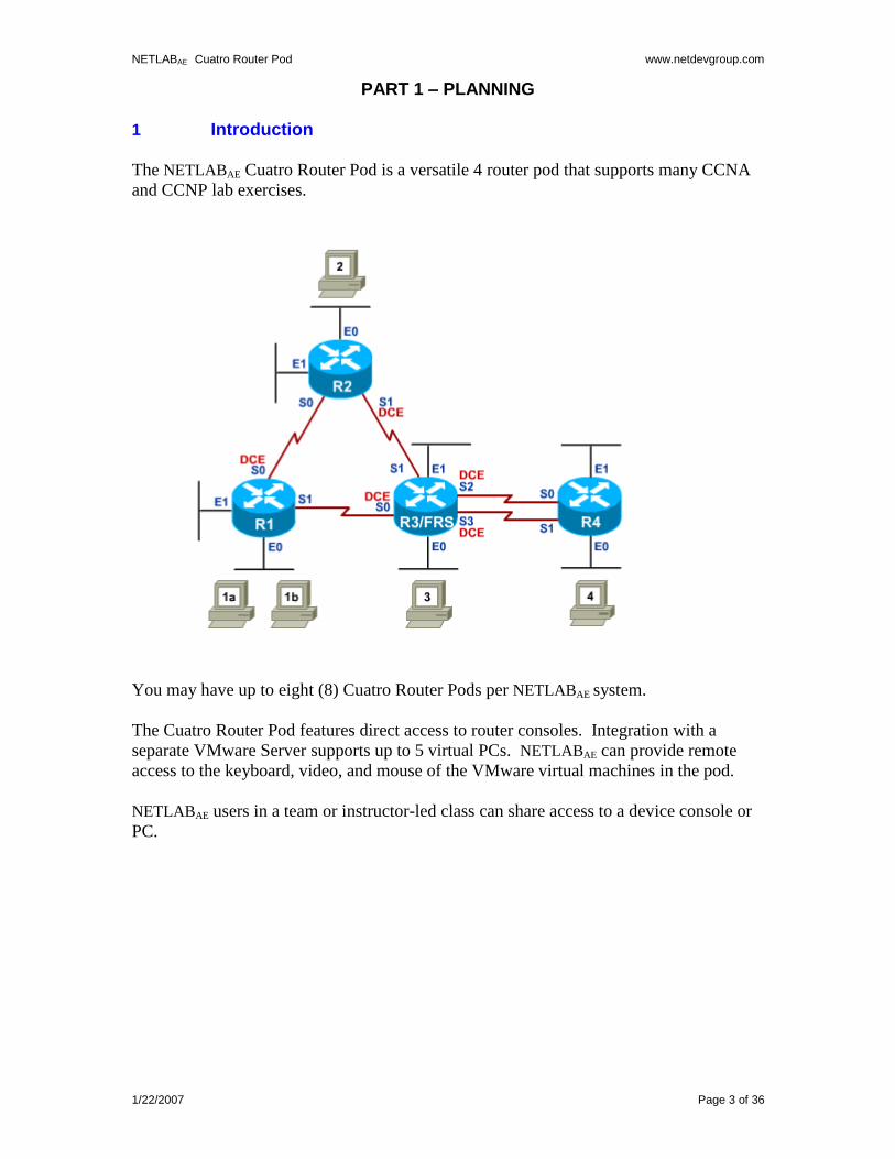
1 Introduction
The NETLABAE Cuatro Router Pod is a versatile 4 router pod that supports many CCNA
and CCNP lab exercises.
You may have up to eight (8) Cuatro Router Pods per NETLABAE system.
The Cuatro Router Pod features direct access to router consoles. Integration with a
separate VMware Server supports up to 5 virtual PCs. NETLABAE can provide remote
access to the keyboard, video, and mouse of the VMware virtual machines in the pod.
NETLABAE users in a team or instructor-led class can share access to a device console or
PC.
NETLABAE Cuatro Router Pod www.netdevgroup.com
1/22/2007 Page 4 of 36
1.1 Deviations
Remote users may get confused by local deviations from the standard curriculum and
labs. The curriculum is relatively complex and offers many opportunities to “make
adjustments to the labs”. If your NETLABAE pods will be made accessible outside your
local Academy, you should carefully consider the impact of deviations and substitutions.
Even if your user community is local or relatively small, we recommend that you (1)
document the specifics of your pods and (2) use the NETLABAE News and
Announcements feature to point users to your documentation.
1.2 Remote PC Support
A Cuatro Router Pod supports up to 5 remote PCs. NETLABAE allows three alternative
settings for each:
Direct/VMware. The PC is implemented as a VMware virtual machine.
o Users can control the keyboard, video, and mouse.
o Users can power on, shutdown, reboot, and revert to a clean state.
o Users can have administrator rights.
Indirect. The PC is implemented, but not managed by NETLABAE.
o Users may be able to interact with the PC, but cannot access the keyboard,
video, or mouse through NETLABAE.
Absent. The PC is not implemented.
These options are fully explained in the NETLAB+ VMware Remote PC Guide.
Direct/VMware offers complete administrative access on the remote PC. To learn more
about VMware Server, please visit http://www.netdevgroup.com/ae/vmware.htm.
Direct/Standalone (as described in the NETLAB+ Remote PC Guide) is not supported on
this pod.
1.3 Dynamic Topologies
The Cuatro Router Pod features dynamic topologies. NETLABAE can alter the topology
and reposition PCs by manipulating VLANs on the control switch. This is done
automatically based on the selected lab exercise. Instructors can change exercises and
topologies during instructor led class reservations.
NETLABAE Cuatro Router Pod www.netdevgroup.com
1/22/2007 Page 5 of 36
2 Lab Device Requirements
Lab devices are part of the topology and users can interact with them either directly or
indirectly.
The equipment listed in subsequent sections is derived from the official Academy
spreadsheet CCNPConfigurationandPricingGuide.xls (November 2006).
Other equipment may work if it is supported by NETLABAE and can meet the minimum
requirements for feature sets, interfaces, IOS, RAM, and Flash. A list of NETLABAE
supported lab equipment can be found on the NDG website. Please note, compatibility
with NETLABAE does not guarantee compatibility with the Academy labs.
2.1 Routers R1, R2, R3 and R4
Router Name
Recommended Routers
Ethernet Ports
Required
Serial Ports
Required
Recommended Serial
Modules
R1, R2, R4
Cisco 1841 Cisco 2801 Cisco 2811
2
2
1 x WIC 2T
R3
Cisco 1841 Cisco 2801 Cisco 2811
2
4
2 x WIC 2T
Several labs will use router R3 as a Frame Relay switch. That is the reason for having
two (2) WIC modules, which means four (4) serial interfaces.
Interface name translation is only supported on two of the four R3 serial interfaces. If you
are deploying more than one Cuatro Router Pod, please use the same router model and
WIC slots for each R3 router to avoid configuration loading problems between pods.
Serial interfaces may be built-in, or provided by modular interface cards such as the
WIC-2T. Serial connections between routers require the appropriate serial cables. You
can use DTE and DCE cables back-to-back, or special cables that provide both DTE and
DCE in one cable (available from SIGMAnet).
NETLABAE Cuatro Router Pod www.netdevgroup.com
1/22/2007 Page 6 of 36
2.2 PCs and Servers
A Cuatro Router Pod supports 5 VMware Server virtual machines. VMware Server is
installed on a separate server.
The following operating system choices are typical based on the curriculum. These
choices are not mandatory; you can make substitutions provided:
(1) VMware Server supports the operating system (as a “guest”).
(2) Your choices are compatible with the curriculum.
Virtual Machine
Recommended O/S
Functions
PC1a Windows XP Student PC, client activities
PC1b Windows XP Student PC, client activities
PC2 Windows XP Student PC, client activities
PC3 Windows XP Student PC, client activities
PC4 Windows XP Student PC, client activities
NETLABAE Cuatro Router Pod www.netdevgroup.com
1/22/2007 Page 7 of 36
3 Control Device Requirements
NETLABAE control devices provide internal connectivity, console access, and managed
power. Control devices are dynamically managed by NETLABAE and are not accessible
or configurable by lab users.
The NETLAB+ Administrator Guide explains how to add, change, or delete control
devices.
A Cuatro Router Pod requires the following control device resources:
Control Device Resource Quantity Required
Control Switch 8 consecutive ports 1 reserved port (VMware server)
Access Server 4 lines
Switched Outlet Devices 4 outlets
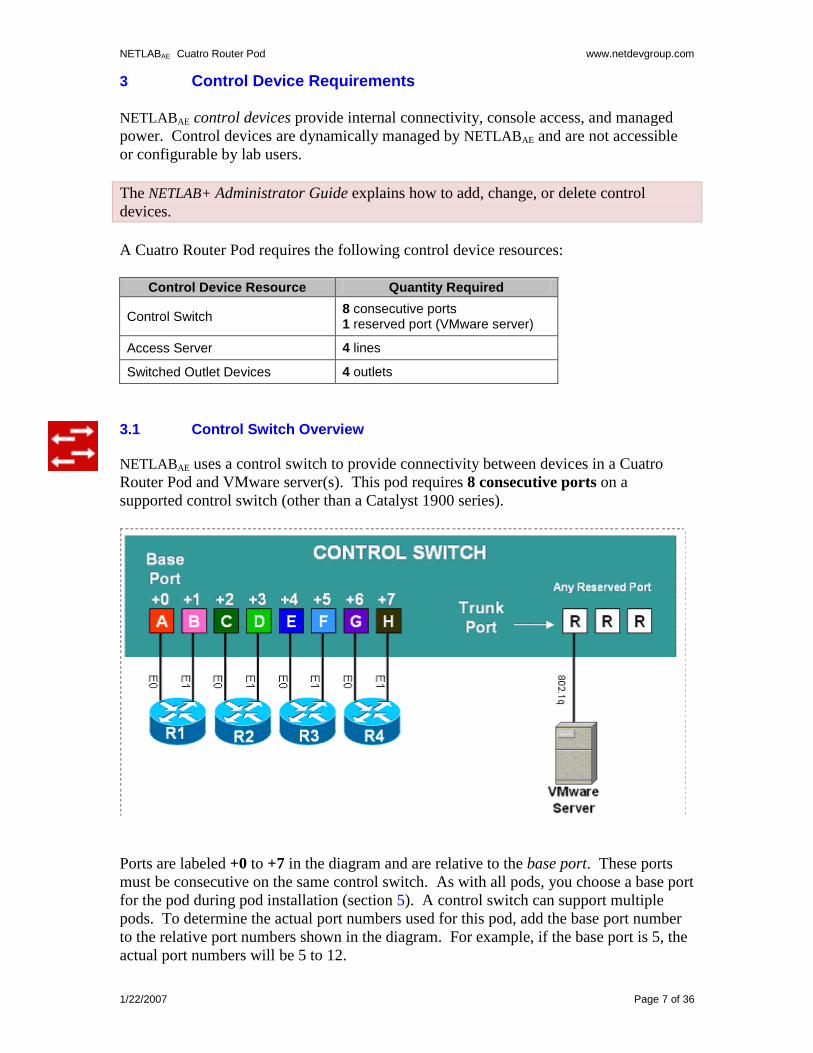
3.1 Control Switch Overview
NETLABAE uses a control switch to provide connectivity between devices in a Cuatro
Router Pod and VMware server(s). This pod requires 8 consecutive ports on a
supported control switch (other than a Catalyst 1900 series).
Ports are labeled +0 to +7 in the diagram and are relative to the base port. These ports
must be consecutive on the same control switch. As with all pods, you choose a base port
for the pod during pod installation (section 5). A control switch can support multiple
pods. To determine the actual port numbers used for this pod, add the base port number
to the relative port numbers shown in the diagram. For example, if the base port is 5, the
actual port numbers will be 5 to 12.
NETLABAE Cuatro Router Pod www.netdevgroup.com
1/22/2007 Page 8 of 36
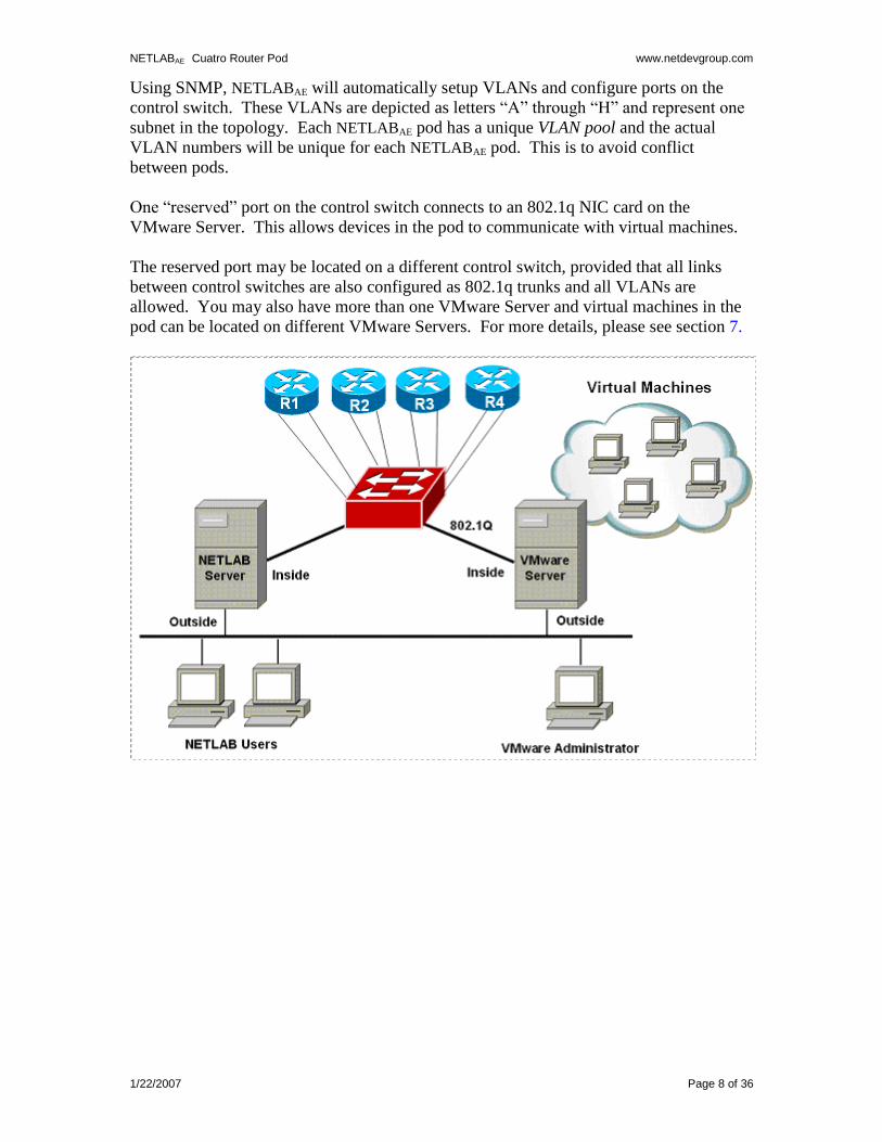
Using SNMP, NETLABAE will automatically setup VLANs and configure ports on the
control switch. These VLANs are depicted as letters “A” through “H” and represent one
subnet in the topology. Each NETLABAE pod has a unique VLAN pool and the actual
VLAN numbers will be unique for each NETLABAE pod. This is to avoid conflict
between pods.
One “reserved” port on the control switch connects to an 802.1q NIC card on the
VMware Server. This allows devices in the pod to communicate with virtual machines.
The reserved port may be located on a different control switch, provided that all links
between control switches are also configured as 802.1q trunks and all VLANs are
allowed. You may also have more than one VMware Server and virtual machines in the
pod can be located on different VMware Servers. For more details, please see section 7.
NETLABAE Cuatro Router Pod www.netdevgroup.com
1/22/2007 Page 9 of 36
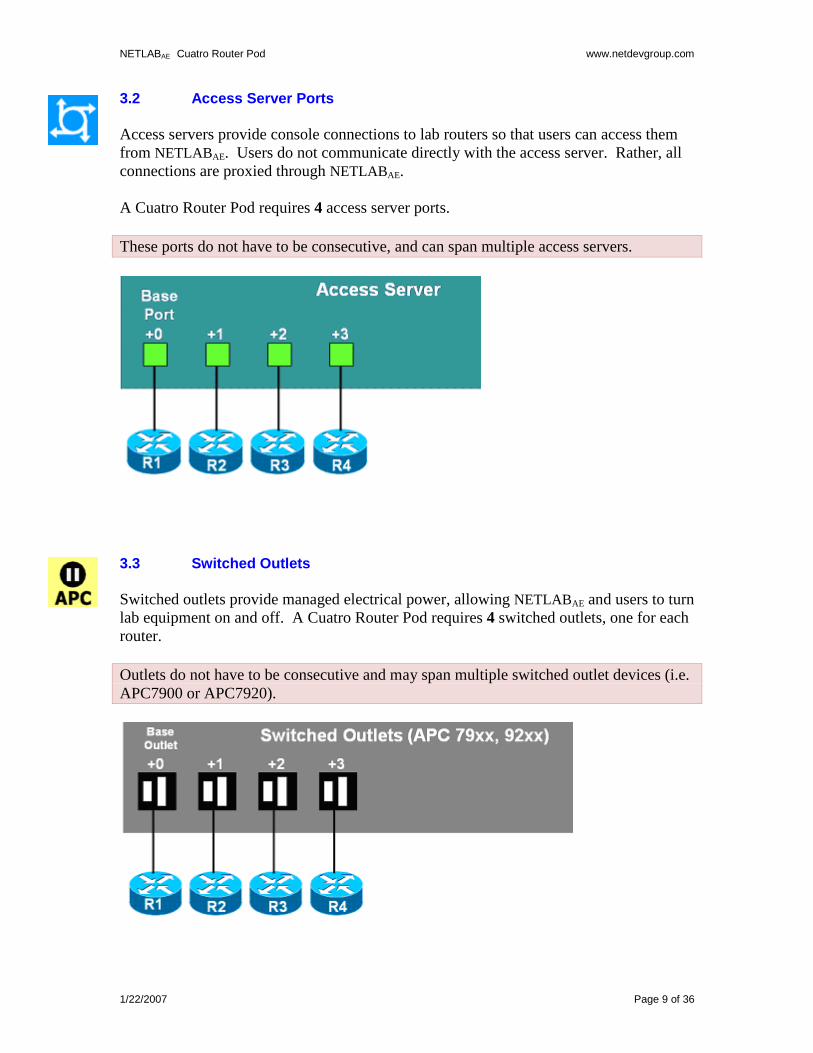
3.2 Access Server Ports
Access servers provide console connections to lab routers so that users can access them
from NETLABAE. Users do not communicate directly with the access server. Rather, all
connections are proxied through NETLABAE.
A Cuatro Router Pod requires 4 access server ports.
These ports do not have to be consecutive, and can span multiple access servers.
3.3 Switched Outlets
Switched outlets provide managed electrical power, allowing NETLABAE and users to turn
lab equipment on and off. A Cuatro Router Pod requires 4 switched outlets, one for each
router.
Outlets do not have to be consecutive and may span multiple switched outlet devices (i.e.
APC7900 or APC7920).
NETLABAE Cuatro Router Pod www.netdevgroup.com
1/22/2007 Page 10 of 36
PART 2 – IMPLEMENTATION
4 Pre-requisites
This section covers tasks that should be executed prior to adding a Cuatro Router Pod.
4.1 Understanding VMware Server and Virtual Machines
The NETLAB+ VMware PC Remote Guide contains essential information for setting up a
VMware Server and virtual machines. It should be used in conjunction with this guide.
4.2 Setup Control Devices
Using the guidelines in section 3, decide which control switch ports, access
server ports, and switched outlets you will use for your Cuatro Router Pod.
Add control devices if necessary. Control device configuration is
documented in the NETLAB+ Administrator Guide.
4.3 Upload IOS Images
Upload the IOS images for the lab routers. NETLABAE will recover these
images on the devices if they are erased from flash.
4.4 Disable User Logins (optional)
You must take all equipment pods offline to add pods or configure control
devices. You may wish to disable user logins during this time.
NETLABAE Cuatro Router Pod www.netdevgroup.com
1/22/2007 Page 11 of 36
5 Adding the Pod
This section walks you through the process of adding a Cuatro Router Pod using the
NETLABAE New Pod Wizard.
5.1 Start the New Pod Wizard
Login to the administrator account.
Select Equipment Pods.
Select Take All OFFLINE if any of the pods are online. Caution: this will cancel any
reservations in progress.
Select Add a Pod.
The New Pod Wizard will now help you add an equipment pod to your system.
5.2 Add a Cuatro Router Pod
When prompted, select the Cuatro Router Pod .
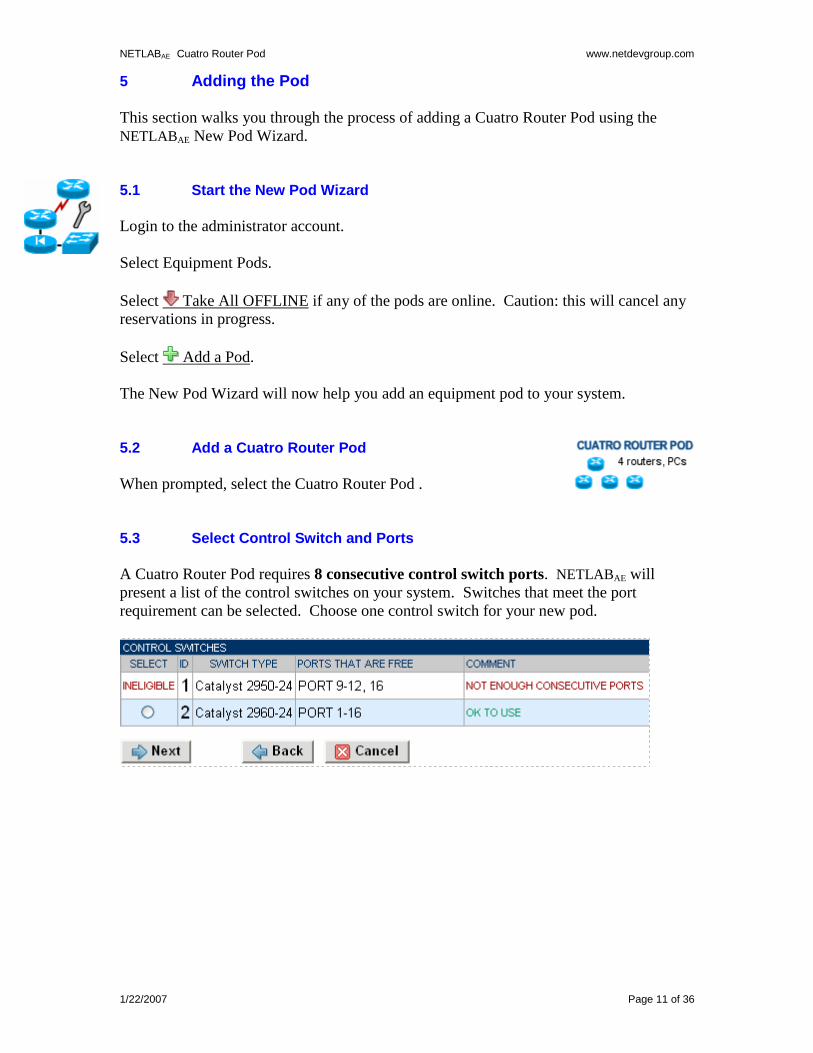
5.3 Select Control Switch and Ports
A Cuatro Router Pod requires 8 consecutive control switch ports. NETLABAE will
present a list of the control switches on your system. Switches that meet the port
requirement can be selected. Choose one control switch for your new pod.
NETLABAE Cuatro Router Pod www.netdevgroup.com
1/22/2007 Page 12 of 36
Next, select the ports you want to use.
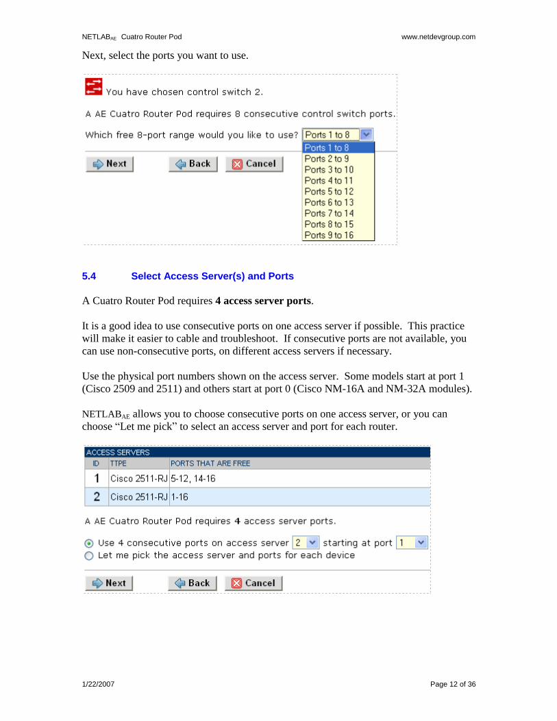
5.4 Select Access Server(s) and Ports
A Cuatro Router Pod requires 4 access server ports.
It is a good idea to use consecutive ports on one access server if possible. This practice
will make it easier to cable and troubleshoot. If consecutive ports are not available, you
can use non-consecutive ports, on different access servers if necessary.
Use the physical port numbers shown on the access server. Some models start at port 1
(Cisco 2509 and 2511) and others start at port 0 (Cisco NM-16A and NM-32A modules).
NETLABAE allows you to choose consecutive ports on one access server, or you can
choose “Let me pick” to select an access server and port for each router.
NETLABAE Cuatro Router Pod www.netdevgroup.com
1/22/2007 Page 13 of 36
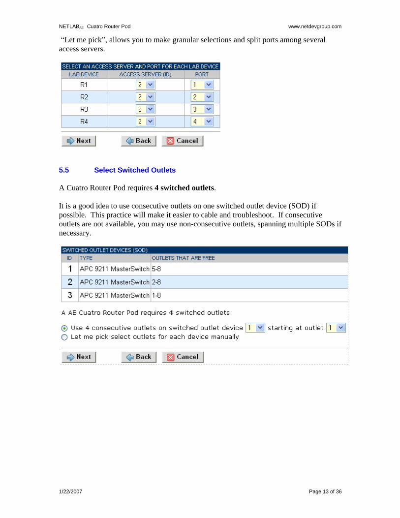
“Let me pick”, allows you to make granular selections and split ports among several
access servers.
5.5 Select Switched Outlets
A Cuatro Router Pod requires 4 switched outlets.
It is a good idea to use consecutive outlets on one switched outlet device (SOD) if
possible. This practice will make it easier to cable and troubleshoot. If consecutive
outlets are not available, you may use non-consecutive outlets, spanning multiple SODs if
necessary.
NETLABAE Cuatro Router Pod www.netdevgroup.com
1/22/2007 Page 14 of 36
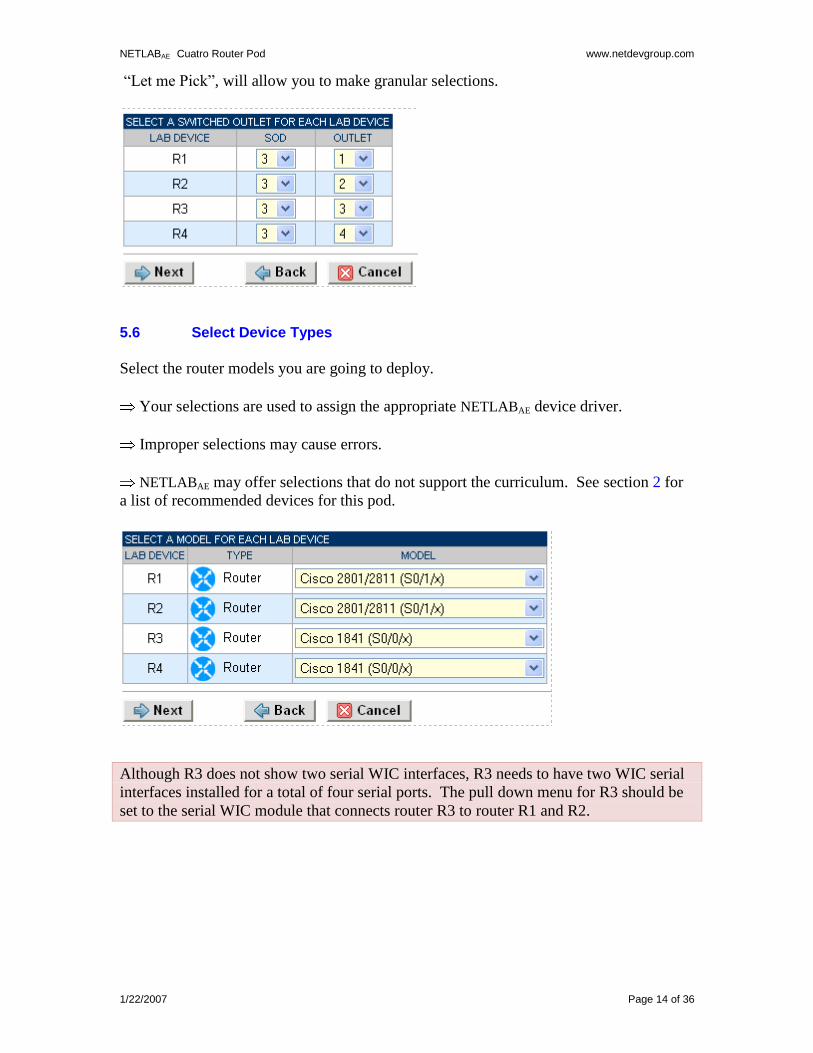
“Let me Pick”, will allow you to make granular selections.
5.6 Select Device Types
Select the router models you are going to deploy.
Your selections are used to assign the appropriate NETLABAE device driver.
Improper selections may cause errors.
NETLABAE may offer selections that do not support the curriculum. See section 2 for
a list of recommended devices for this pod.
Although R3 does not show two serial WIC interfaces, R3 needs to have two WIC serial
interfaces installed for a total of four serial ports. The pull down menu for R3 should be
set to the serial WIC module that connects router R3 to router R1 and R2.
NETLABAE Cuatro Router Pod www.netdevgroup.com
1/22/2007 Page 15 of 36
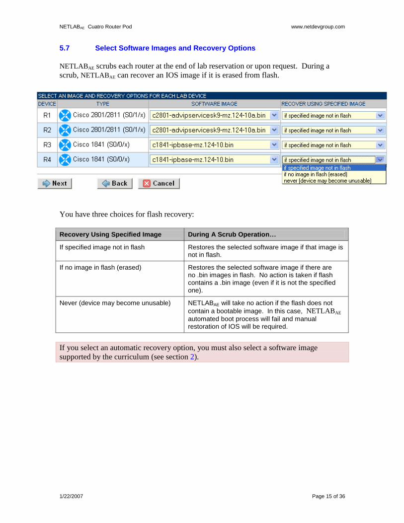
5.7 Select Software Images and Recovery Options
NETLABAE scrubs each router at the end of lab reservation or upon request. During a
scrub, NETLABAE can recover an IOS image if it is erased from flash.
You have three choices for flash recovery:
Recovery Using Specified Image During A Scrub Operation…
If specified image not in flash Restores the selected software image if that image is not in flash.
If no image in flash (erased) Restores the selected software image if there are no .bin images in flash. No action is taken if flash contains a .bin image (even if it is not the specified one).
Never (device may become unusable) NETLABAE will take no action if the flash does not
contain a bootable image. In this case, NETLABAE automated boot process will fail and manual restoration of IOS will be required.
If you select an automatic recovery option, you must also select a software image
supported by the curriculum (see section 2).
NETLABAE Cuatro Router Pod www.netdevgroup.com
1/22/2007 Page 16 of 36
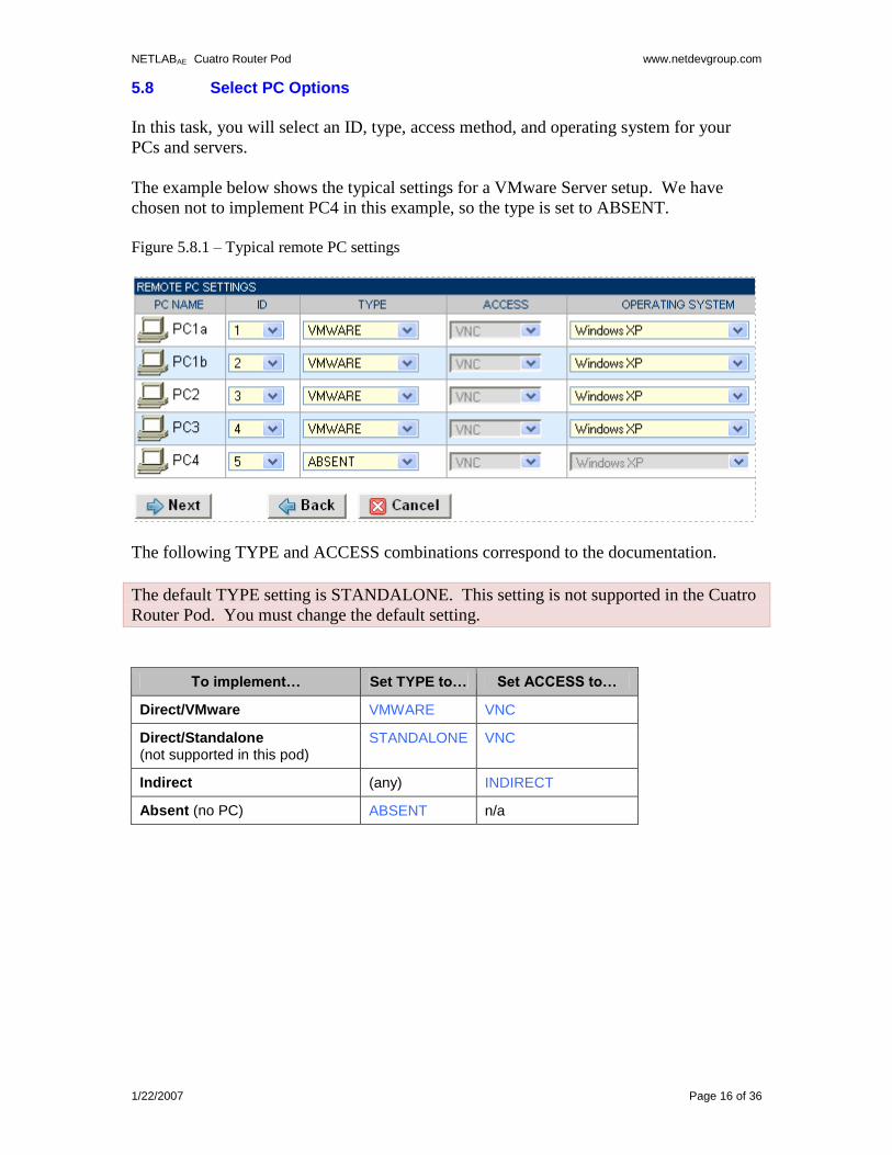
5.8 Select PC Options
In this task, you will select an ID, type, access method, and operating system for your
PCs and servers.
The example below shows the typical settings for a VMware Server setup. We have
chosen not to implement PC4 in this example, so the type is set to ABSENT.
Figure 5.8.1 – Typical remote PC settings
The following TYPE and ACCESS combinations correspond to the documentation.
The default TYPE setting is STANDALONE. This setting is not supported in the Cuatro
Router Pod. You must change the default setting.
To implement… Set TYPE to… Set ACCESS to…
Direct/VMware VMWARE VNC
Direct/Standalone (not supported in this pod)
STANDALONE VNC
Indirect (any) INDIRECT
Absent (no PC) ABSENT n/a
NETLABAE Cuatro Router Pod www.netdevgroup.com
1/22/2007 Page 17 of 36
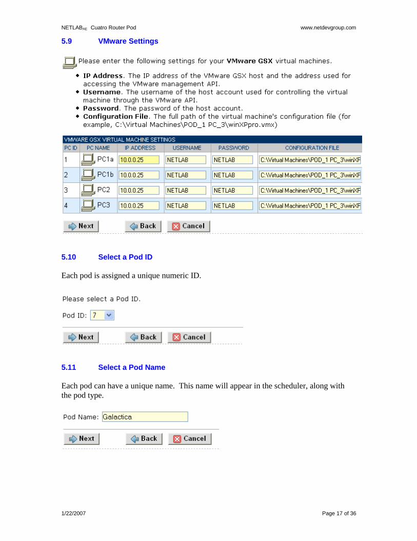
5.9 VMware Settings
5.10 Select a Pod ID
Each pod is assigned a unique numeric ID.
5.11 Select a Pod Name
Each pod can have a unique name. This name will appear in the scheduler, along with
the pod type.
NETLABAE Cuatro Router Pod www.netdevgroup.com
1/22/2007 Page 18 of 36
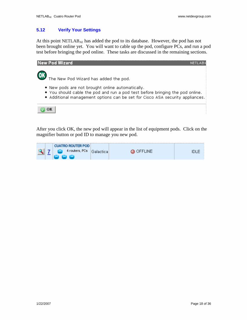
5.12 Verify Your Settings
At this point NETLABAE has added the pod to its database. However, the pod has not
been brought online yet. You will want to cable up the pod, configure PCs, and run a pod
test before bringing the pod online. These tasks are discussed in the remaining sections.
After you click OK, the new pod will appear in the list of equipment pods. Click on the
magnifier button or pod ID to manage you new pod.
NETLABAE Cuatro Router Pod www.netdevgroup.com
1/22/2007 Page 19 of 36
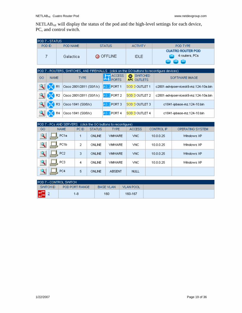
NETLABAE will display the status of the pod and the high-level settings for each device,
PC, and control switch.
NETLABAE Cuatro Router Pod www.netdevgroup.com
1/22/2007 Page 20 of 36
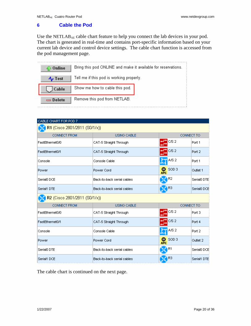
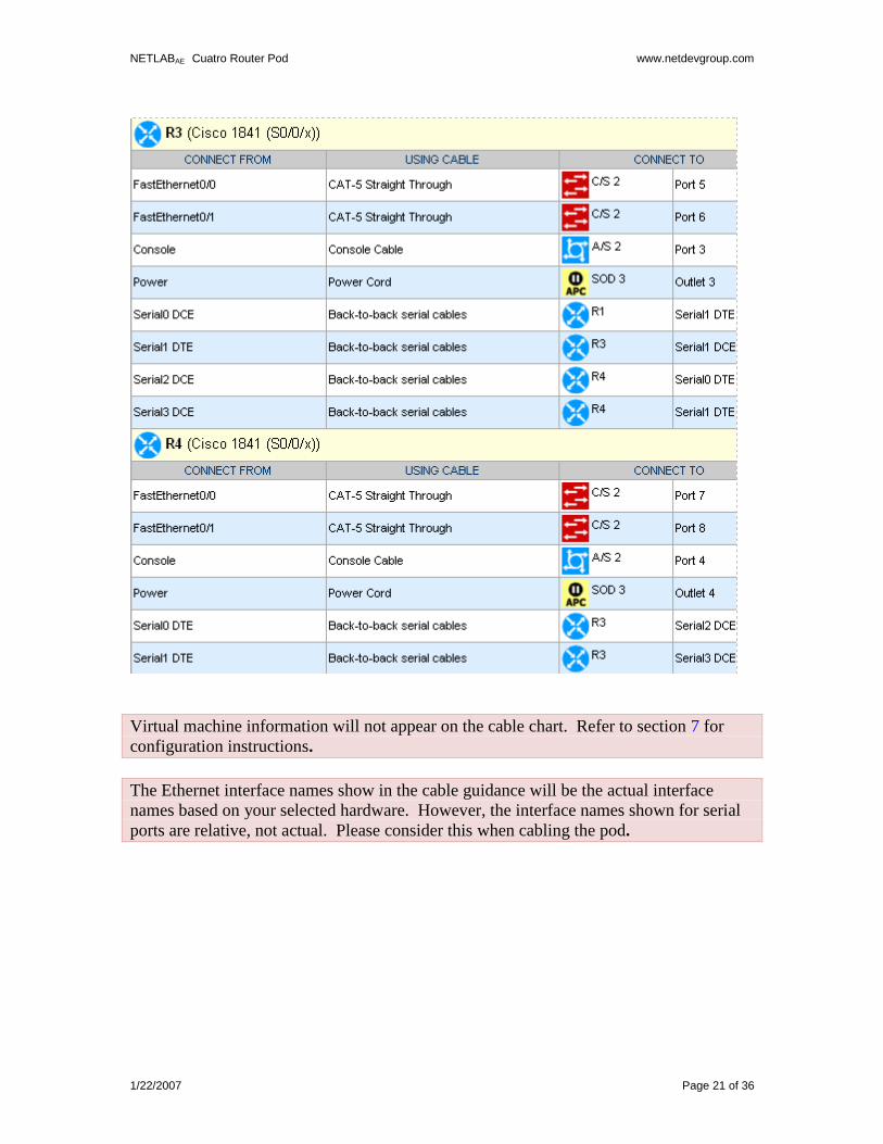
6 Cable the Pod
Use the NETLABAE cable chart feature to help you connect the lab devices in your pod.
The chart is generated in real-time and contains port-specific information based on your
current lab device and control device settings. The cable chart function is accessed from
the pod management page.
The cable chart is continued on the next page.
NETLABAE Cuatro Router Pod www.netdevgroup.com
1/22/2007 Page 21 of 36
Virtual machine information will not appear on the cable chart. Refer to section 7 for
configuration instructions.
The Ethernet interface names show in the cable guidance will be the actual interface
names based on your selected hardware. However, the interface names shown for serial
ports are relative, not actual. Please consider this when cabling the pod.
NETLABAE Cuatro Router Pod www.netdevgroup.com
1/22/2007 Page 22 of 36
7 Configuring VMware and Virtual Machines
The NETLAB+ VMware Remote PC Guide explains how to set up VMware Server and
virtual machines. Please review the pod-specific information in this section and apply it
to the general information in the NETLAB+ VMware Remote PC Guide. Please note, only
the sections referring to VMware are relevant; a Cuatro Router Pod does not support
standalone PC’s.
After you load applications or make changes to a PC, be sure to take a VMware snapshot.
NETLABAE instructs VMware to “revert” to the snapshot at the end of each lab
reservation. Any changes made after a snapshot are lost.
The IP addresses and/or default gateways of each PC may vary. Depending on your
snapshots, the student may need to adjust IP settings to reflect the lab.
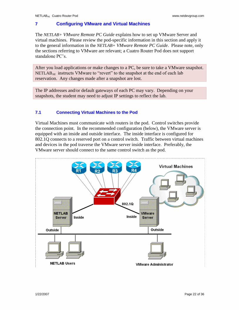
7.1 Connecting Virtual Machines to the Pod
Virtual Machines must communicate with routers in the pod. Control switches provide
the connection point. In the recommended configuration (below), the VMware server is
equipped with an inside and outside interface. The inside interface is configured for
802.1Q connects to a reserved port on a control switch. Traffic between virtual machines
and devices in the pod traverse the VMware server inside interface. Preferably, the
VMware server should connect to the same control switch as the pod.
NETLABAE Cuatro Router Pod www.netdevgroup.com
1/22/2007 Page 23 of 36
7.2 VMware Virtual Switches and VLANs
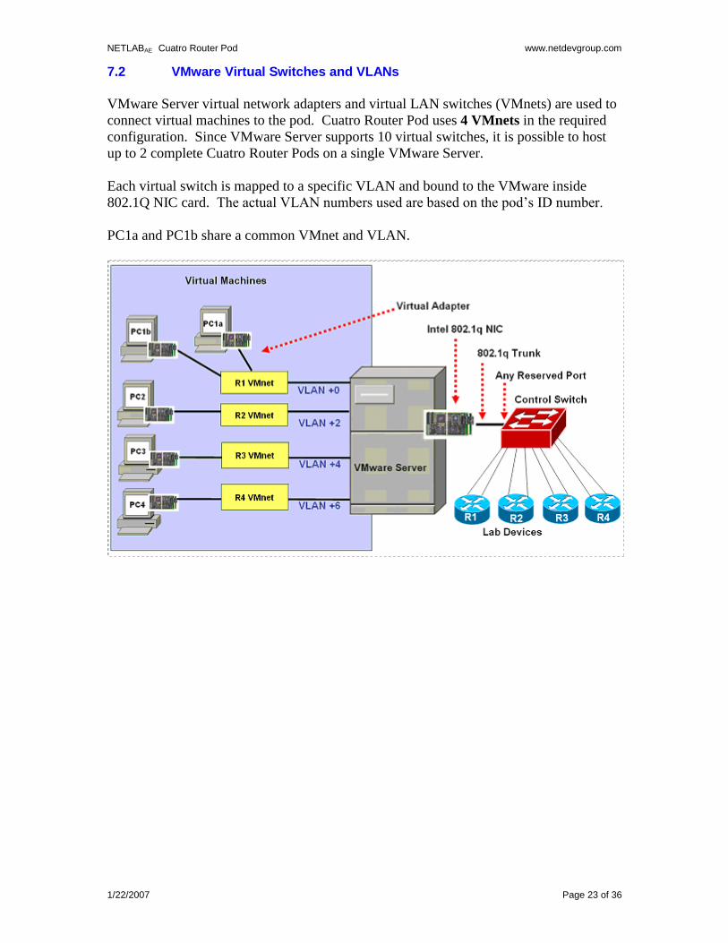
VMware Server virtual network adapters and virtual LAN switches (VMnets) are used to
connect virtual machines to the pod. Cuatro Router Pod uses 4 VMnets in the required
configuration. Since VMware Server supports 10 virtual switches, it is possible to host
up to 2 complete Cuatro Router Pods on a single VMware Server.
Each virtual switch is mapped to a specific VLAN and bound to the VMware inside
802.1Q NIC card. The actual VLAN numbers used are based on the pod’s ID number.
PC1a and PC1b share a common VMnet and VLAN.
NETLABAE Cuatro Router Pod www.netdevgroup.com
1/22/2007 Page 24 of 36
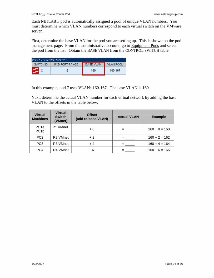
Each NETLABAE pod is automatically assigned a pool of unique VLAN numbers. You
must determine which VLAN numbers correspond to each virtual switch on the VMware
server.
First, determine the base VLAN for the pod you are setting up. This is shown on the pod
management page. From the administrative account, go to Equipment Pods and select
the pod from the list. Obtain the BASE VLAN from the CONTROL SWITCH table.
In this example, pod 7 uses VLANs 160-167. The base VLAN is 160.
Next, determine the actual VLAN number for each virtual network by adding the base
VLAN to the offsets in the table below.
Virtual Machines
Virtual Switch (VMnet)
Offset (add to base VLAN)
Actual VLAN Example
PC1a PC1b
R1 VMnet
+ 0 = _____ 160 + 0 = 160
PC2 R2 VMnet + 2 = _____ 160 + 2 = 162
PC3 R3 VMnet + 4 = _____ 160 + 4 = 164
PC4 R4 VMnet +6 = _____ 160 + 6 = 166
NETLABAE Cuatro Router Pod www.netdevgroup.com
1/22/2007 Page 25 of 36
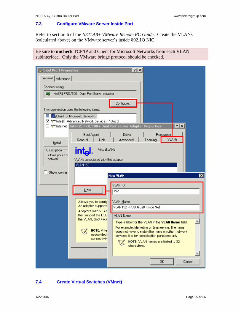
7.3 Configure VMware Server Inside Port
Refer to section 6 of the NETLAB+ VMware Remote PC Guide. Create the VLANs
(calculated above) on the VMware server’s inside 802.1Q NIC.
Be sure to uncheck TCP/IP and Client for Microsoft Networks from each VLAN
subinterface. Only the VMware bridge protocol should be checked.
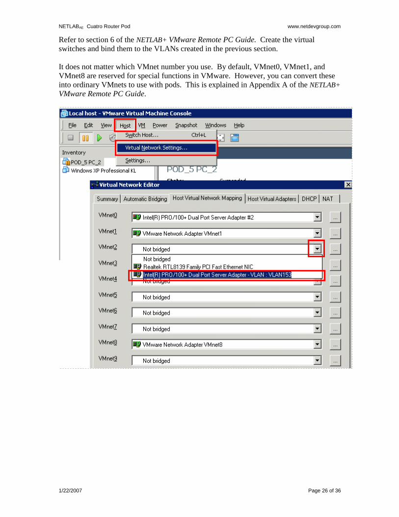
7.4 Create Virtual Switches (VMnet)
NETLABAE Cuatro Router Pod www.netdevgroup.com
1/22/2007 Page 26 of 36
Refer to section 6 of the NETLAB+ VMware Remote PC Guide. Create the virtual
switches and bind them to the VLANs created in the previous section.
It does not matter which VMnet number you use. By default, VMnet0, VMnet1, and
VMnet8 are reserved for special functions in VMware. However, you can convert these
into ordinary VMnets to use with pods. This is explained in Appendix A of the NETLAB+
VMware Remote PC Guide.
NETLABAE Cuatro Router Pod www.netdevgroup.com
1/22/2007 Page 27 of 36
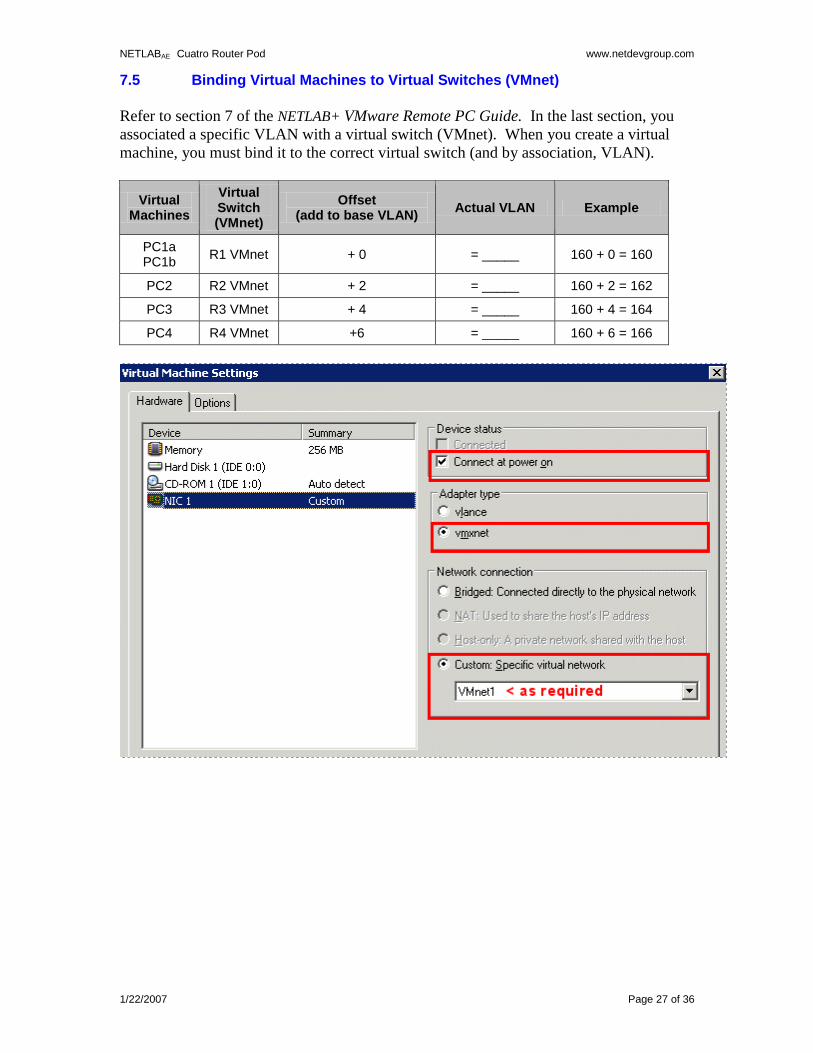
7.5 Binding Virtual Machines to Virtual Switches (VMnet)
Refer to section 7 of the NETLAB+ VMware Remote PC Guide. In the last section, you
associated a specific VLAN with a virtual switch (VMnet). When you create a virtual
machine, you must bind it to the correct virtual switch (and by association, VLAN).
Virtual Machines
Virtual Switch (VMnet)
Offset (add to base VLAN)
Actual VLAN Example
PC1a PC1b
R1 VMnet + 0 = _____ 160 + 0 = 160
PC2 R2 VMnet + 2 = _____ 160 + 2 = 162
PC3 R3 VMnet + 4 = _____ 160 + 4 = 164
PC4 R4 VMnet +6 = _____ 160 + 6 = 166
NETLABAE Cuatro Router Pod www.netdevgroup.com
1/22/2007 Page 28 of 36
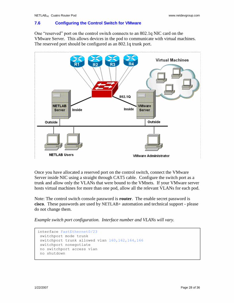
7.6 Configuring the Control Switch for VMware
One “reserved” port on the control switch connects to an 802.1q NIC card on the
VMware Server. This allows devices in the pod to communicate with virtual machines.
The reserved port should be configured as an 802.1q trunk port.
Once you have allocated a reserved port on the control switch, connect the VMware
Server inside NIC using a straight through CAT5 cable. Configure the switch port as a
trunk and allow only the VLANs that were bound to the VMnets. If your VMware server
hosts virtual machines for more than one pod, allow all the relevant VLANs for each pod.
Note: The control switch console password is router. The enable secret password is
cisco. These passwords are used by NETLAB+ automation and technical support - please
do not change them.
Example switch port configuration. Interface number and VLANs will vary.
interface FastEthernet0/23
switchport mode trunk
switchport trunk allowed vlan 160,162,164,166
switchport nonegotiate
no switchport access vlan
no shutdown
NETLABAE Cuatro Router Pod www.netdevgroup.com
1/22/2007 Page 29 of 36
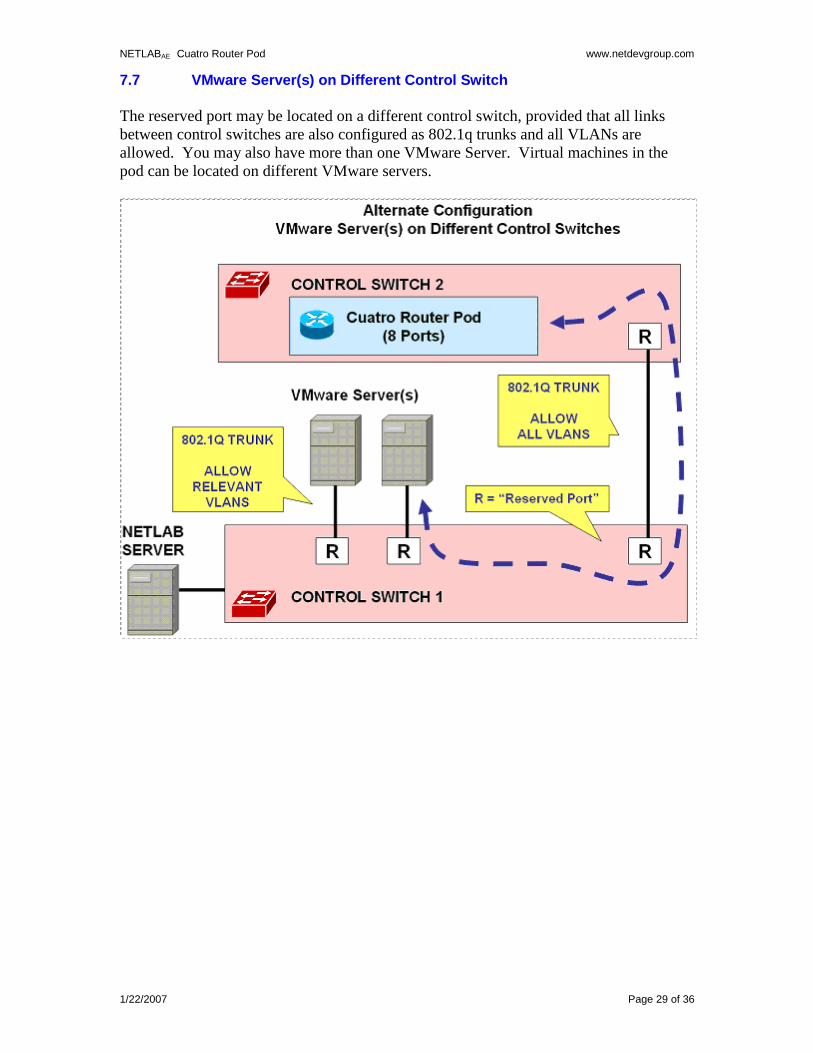
7.7 VMware Server(s) on Different Control Switch
The reserved port may be located on a different control switch, provided that all links
between control switches are also configured as 802.1q trunks and all VLANs are
allowed. You may also have more than one VMware Server. Virtual machines in the
pod can be located on different VMware servers.
NETLABAE Cuatro Router Pod www.netdevgroup.com
1/22/2007 Page 30 of 36
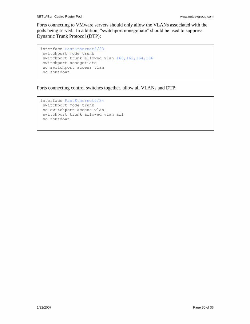
Ports connecting to VMware servers should only allow the VLANs associated with the
pods being served. In addition, “switchport nonegotiate” should be used to suppress
Dynamic Trunk Protocol (DTP):
Ports connecting control switches together, allow all VLANs and DTP:
interface FastEthernet0/24
switchport mode trunk
no switchport access vlan
switchport trunk allowed vlan all
no shutdown
interface FastEthernet0/23
switchport mode trunk
switchport trunk allowed vlan 160,162,164,166
switchport nonegotiate
no switchport access vlan
no shutdown
NETLABAE Cuatro Router Pod www.netdevgroup.com
1/22/2007 Page 31 of 36
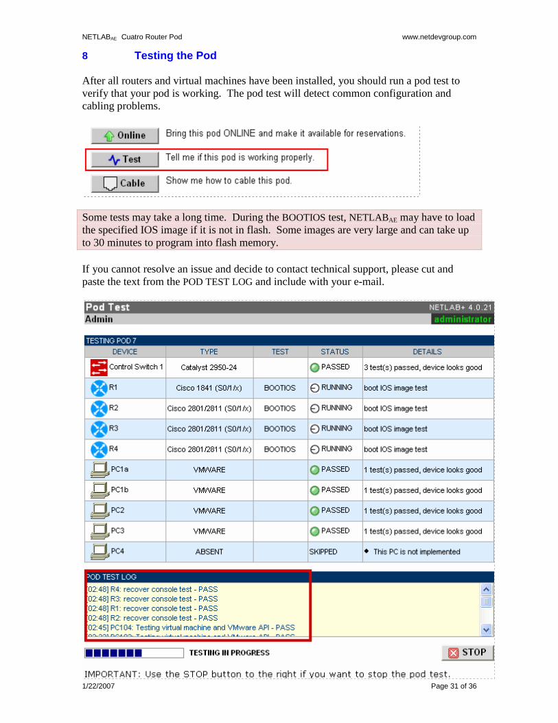
8 Testing the Pod
After all routers and virtual machines have been installed, you should run a pod test to
verify that your pod is working. The pod test will detect common configuration and
cabling problems.
Some tests may take a long time. During the BOOTIOS test, NETLABAE may have to load
the specified IOS image if it is not in flash. Some images are very large and can take up
to 30 minutes to program into flash memory.
If you cannot resolve an issue and decide to contact technical support, please cut and
paste the text from the POD TEST LOG and include with your e-mail.
NETLABAE Cuatro Router Pod www.netdevgroup.com
1/22/2007 Page 32 of 36
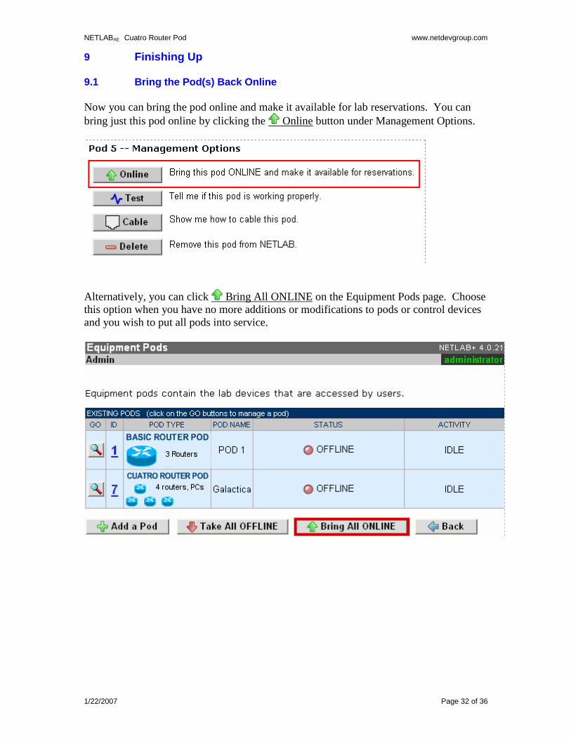
9 Finishing Up 9.1 Bring the Pod(s) Back Online
Now you can bring the pod online and make it available for lab reservations. You can
bring just this pod online by clicking the Online button under Management Options.
Alternatively, you can click Bring All ONLINE on the Equipment Pods page. Choose
this option when you have no more additions or modifications to pods or control devices
and you wish to put all pods into service.
NETLABAE Cuatro Router Pod www.netdevgroup.com
1/22/2007 Page 33 of 36
9.2 Enable Cuatro Router Pod Exercises
To make Cuatro Router Pod available to classes and students, you must enable the
corresponding lab exercise content in each new or existing class.
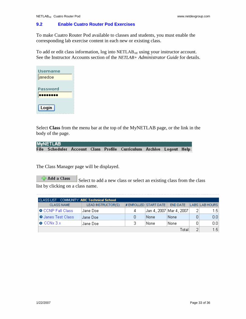
To add or edit class information, log into NETLABAE using your instructor account.
See the Instructor Accounts section of the NETLAB+ Administrator Guide for details.
Select Class from the menu bar at the top of the MyNETLAB page, or the link in the
body of the page.
The Class Manager page will be displayed.
Select to add a new class or select an existing class from the class
list by clicking on a class name.
NETLABAE Cuatro Router Pod www.netdevgroup.com
1/22/2007 Page 34 of 36
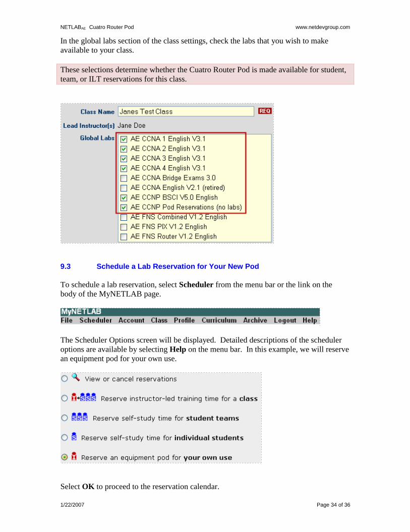
In the global labs section of the class settings, check the labs that you wish to make
available to your class.
These selections determine whether the Cuatro Router Pod is made available for student,
team, or ILT reservations for this class.
9.3 Schedule a Lab Reservation for Your New Pod
To schedule a lab reservation, select Scheduler from the menu bar or the link on the
body of the MyNETLAB page.
The Scheduler Options screen will be displayed. Detailed descriptions of the scheduler
options are available by selecting Help on the menu bar. In this example, we will reserve
an equipment pod for your own use.
Select OK to proceed to the reservation calendar.
NETLABAE Cuatro Router Pod www.netdevgroup.com
1/22/2007 Page 35 of 36
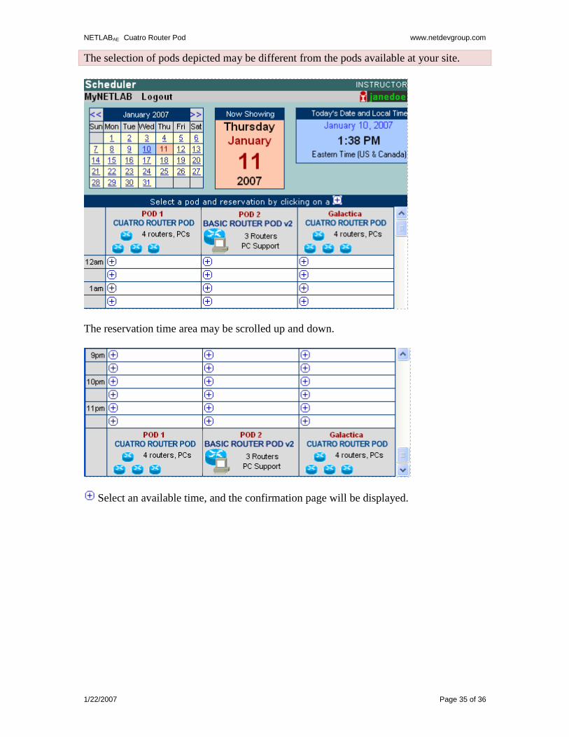
The selection of pods depicted may be different from the pods available at your site.
The reservation time area may be scrolled up and down.
Select an available time, and the confirmation page will be displayed.
NETLABAE Cuatro Router Pod www.netdevgroup.com
1/22/2007 Page 36 of 36
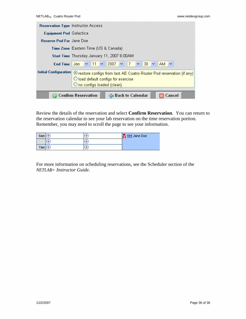
Review the details of the reservation and select Confirm Reservation. You can return to
the reservation calendar to see your lab reservation on the time reservation portion.
Remember, you may need to scroll the page to see your information.
For more information on scheduling reservations, see the Scheduler section of the
NETLAB+ Instructor Guide.