ctara report
TRANSCRIPT

Dug Well Water Measuring and Logging Device
CTARA
Pushkar Limaye, 09010024Sankalp Kelshikar, 09010017
Akash Goel, 09010014

CONTENTS
1 Introduction
Aim of the project
2 The Mechanical device
Implementation and Testing
o Mechanical Part
o Electronics Part
o Algorithm & Coding
3 The SONAR device
Implementation and Testing
o Electronic Part
o Algorithm & The code
Increasing Range of the Sensor
4 Feasibility Analysis and Future Resourcefulness
1

INTRODUCTION
AIM OF THE PROJECT
• The objective of the project is to make an portable device for measuring well water levels which should be-
• low power
• easy to use and transport
• accurate (upto 3mm)
• Support additional features expected from a hand-held system.
• Structural Requirements
• The device should have a screen on it and should accurately measure and display the well water level.
• The device should measure well water level irrespective of the water surface condition.
• The device should be Portable and easy to carry. We found out two different designs - first using SONAR and second using basic mechanics and electronics.
• The device should run on the smallest available battery because remote areas, where the wells are generally situated, might not have appropriate power supply. Thus we make use of rechargeable batteries.
• The device should have a memory storage capacity to keep all the well water level data stored. Thus we have provided a slot to fit a SD memory card.
2

THE MECHANICAL DEVICE
The device is essentially composed of 2 mechanical parts attached by a 2 wire thread- the float (base) and the controller. The idea is to send the float to the water below and calculate the reading of the depth of the well. This is achieved by calculating the total angle travelled by the motor for which we employ a pulley system with a metal proximity switch. We signal to the controller that the float has reached the water by send a 3 volt signal which is activated once a circuit is complete. The slacked thread (when the float floats) between the 2 acrylic sheets ensures a wired connection through which this signal is sent. The float is then brought back up to the controller after the reading is logged into the memory card against the position of the place.
3
IMPLEMENTATION & TESTING
MECHANICAL PART
Pic 1
Pic 2
4
• The metal proximity switch is fitted at the perfect location such that the holes on the pulley are in front of it. We are able to count the exact number of holes which pass by the proximity switch and thus calculate the exact length of wire that has went down in the well. (Refer Pic-1)
• The friction between the wire and the pulley groove is sufficient for the pulley to rotate without slip thus reducing the reading error to almost zero. Also, Reel and the pulley are properly aligned so the angle that wire makes with pulley is minimised. (refer pic-2)
• The wire is strong enough to hold a weight of 500 grams hanging off the device.
• The float sends a signal to the device as soon as it touches the water surface and the response is quick. The float works on all the surface conditions
• All the mechanical part of device work perfectly fine and all the connections with the electrical part are done.
Following are the photos of the pulley, reel and the fittings
5
ELECTRONICS PART
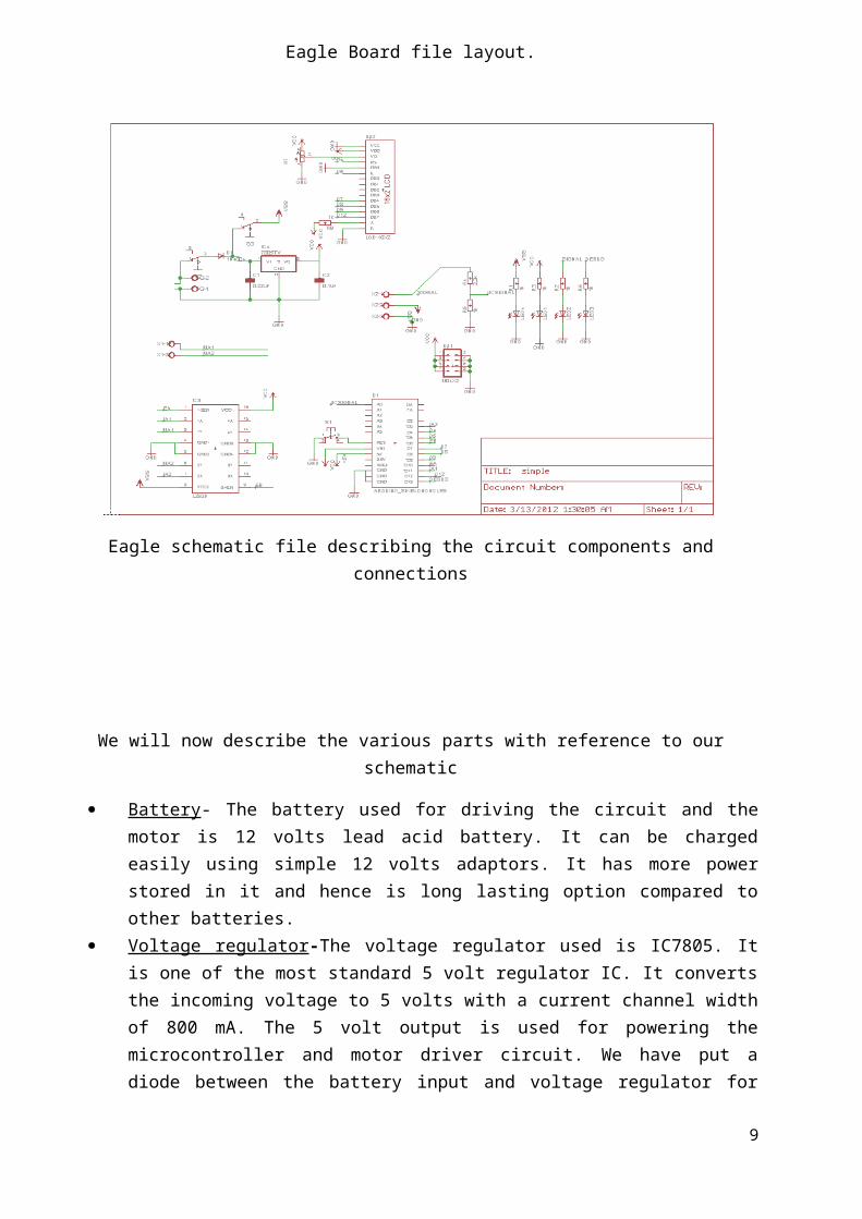
The above picture shows the Printed board we made for this purpose. This circuit basically makes the pulley rotate until it senses that the lower end has touched the water surface. Thus, by measuring the amount of rotation, it finds out the distance using simple geometric equations. To display the output, it has a 20*4 LCD screen attached to it. As seen in the picture, we have provided it with onboard voltage regulator with heat sink, debugging LEDs, switches and power ports etc. to make it a expandable application in future.
Here is the Eagle schematic and board diagram of the same. Eagle is software used for making the layouts of printed PCB boards.
6

Eagle Board file layout.
Eagle schematic file describing the circuit components and connections
We will now describe the various parts with reference to our schematic
7
Battery - The battery used for driving the circuit and the motor is 12 volts lead acid battery. It can be charged easily using simple 12 volts adaptors. It has more power stored in it and hence is long lasting option compared to other batteries.
Voltage regulator -The voltage regulator used is IC7805. It is one of the most standard 5 volt regulator IC. It converts the incoming voltage to 5 volts with a current channel width of 800 mA. The 5 volt output is used for powering the microcontroller and motor driver circuit. We have put a diode between the battery input and voltage regulator for reverse polarity protection of the circuit. For protection against heat generation, we have attached a standard fin shaped heat sink on top of the regulator.
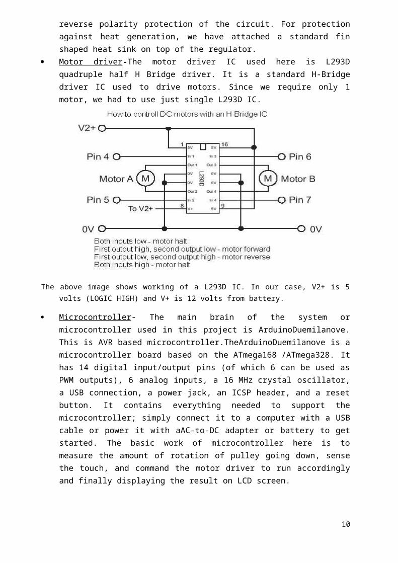
Motor driver -The motor driver IC used here is L293D quadruple half H Bridge driver. It is a standard H-Bridge driver IC used to drive motors. Since we require only 1 motor, we had to use just single L293D IC.
The above image shows working of a L293D IC. In our case, V2+ is 5 volts (LOGIC HIGH) and V+ is 12 volts from battery.
Microcontroller - The main brain of the system or microcontroller used in this project is ArduinoDuemilanove. This is AVR based microcontroller.TheArduinoDuemilanove is a microcontroller board based on the ATmega168 /ATmega328. It has 14 digital input/output pins (of which 6 can be used as PWM outputs), 6 analog inputs, a 16 MHz crystal oscillator, a USB connection, a power jack, an ICSP header, and a reset button. It contains everything needed to support the microcontroller; simply connect it to a computer with a USB cable or power it with aAC-to-DC adapter or battery to get started. The basic work of microcontroller here is to measure the amount of rotation of pulley going down, sense the touch, and command the motor driver to run accordingly and finally displaying the result on LCD screen.
8
Metal proximity switch - This is a hall effect based sensor whose voltage output value goes high if it comes within 2 mm proximity of a metal.
LCD display - The LCD display screen used in this case is 20*4 character LCD screen.It is done by using the Arduino’s liquid crystal library file. Since arduino is open source software,this library is available for everyone to use. The Liquid Crystallibrary works with all LCD displays that are compatible with the Hitachi HD44780 driver.
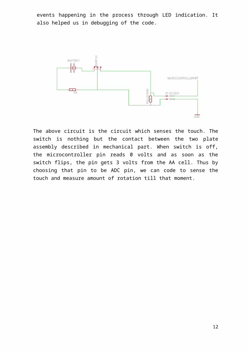
Debugging LEDs and power port -Apart from normal routing to the microcontroller pin, we also kept a power port for taking +5 volts & ground for any additional connection. Debugging LEDs are kept for the user to observe various events happening in the process through LED indication. It also helped us in debugging of the code.
9
The above circuit is the circuit which senses the touch. The switch is nothing but the contact between the two plate assembly described in mechanical part. When switch is off, the microcontroller pin reads 0 volts and as soon as the switch flips, the pin gets 3 volts from the AA cell. Thus by choosing that pin to be ADC pin, we can code to sense the touch and measure amount of rotation till that moment.
ALGORITHM AND CODING
10

When we press the start switch, the motor starts rotating in the CW direction. The metal proximity sensor counts the total angle through which the pulley rotates(accurate to 45 degrees).
A counter variable keeps track of this count. When the float touches the water and the thread between the 2 acrylic
sheets is slack, a circuit is completed and a 3 volt signal is sent to the micro controller.
This triggers the motor to rotate in the ACW direction. At this time, the device calculates the total distance the float has travelled i.e. the depth of the well water.
The proximity sensor counts the angle again- the counter variable ensuring that the number of rotations is the same.
The float is brought back up and the device is brought back together. The reading (depth) gets stored in the memory card against the position
of the well for future records.
The code:
#include <LiquidCrystal.h>
intdebugPin=13;
intmetalDetectpin=A0;
int flag=2;
intflagprev=2;
intmotorf=11;
intmotorb=3;
intmotorflag=2;
intsensorPin=A0;
intsensorOut;
int count=0;
intcountprev=0;
longint c=0;
inttouchpin=A2;
LiquidCrystallcd(4,5,7,8,9,12);
void setup(){
Serial.begin(9600);
11
pinMode(debugPin,OUTPUT);
pinMode(motorf,OUTPUT);
pinMode(motorb,OUTPUT);
pinMode(10,OUTPUT);
analogWrite(10,0);
// set up the LCD's number of columns and rows:
lcd.begin(20, 4);
// Print a message to the LCD.
lcd.print("CTARA IITB!");
}
void loop(){
delay(1000);
while(analogRead(touchpin)<512{
motorforward();
sensorRead();
}
//Serial.println(count);
digitalWrite(debugPin,HIGH);
delay(2000);
digitalWrite(debugPin,LOW);
count=countprev;
count=0;
do{
motorbackward();
//sensorRead();
}while(count!=countprev);
digitalWrite(debugPin,HIGH);
delay(2000);
digitalWrite(debugPin,LOW);
12
while(1){
lcdprint()
};
}
voidmotorforward(){
analogWrite(motorf,50);
analogWrite(motorb,0);
}
voidmotorbackward(){
analogWrite(motorb,50);
analogWrite(motorf,0);
}
voidsensorRead(){
flagprev=flag;
sensorOut=analogRead(sensorPin);
if(sensorOut< 100)flag=0;
if(sensorOut>300)flag=1;
if(flag==0 &&flagprev==1)count++;
}
voidlcdprint(){
lcd.setCursor(0, 1);
// print the number of seconds since reset:
lcd.print(count);
}
13

THE SONAR: PRINCIPLE
Sonar is simply making use of an echo. When an animal or machine makes a noise, it sends sound waves into the environment around it. Those waves bounce off nearby objects, and some of them reflect back to the object that made the noise. It's those reflected sound waves that you hear when your voice echoes back to you from a canyon. Whales and specialized machines can use reflected waves to locate distant objects and sense their shape and movement.
14

ELECTRICAL PART
The ultrasonic sensor is capable of detecting objects up to a 3 mts distance. The sensor counts with 3 pins, two are dedicated to power and ground, while the third one is used both as input and output. First we have to send a pulse that will make the sensor send an ultrasound tone and wait for an echo. Once the tone is received back, the sensor will send a pulse over the same pin as earlier. The width of that pulse will determine the distance to the object. This sensor is very similar to the PING sensor from parallax and the code for the same works with this. Since the current requirement is not so high (within 50mA), we can simply use the on-board voltage regulator of the Arduino board to power up the sonar sensor.
The sensor we used is ultrasonic ping sensor from parallax company.
Parallax's PING))) ™ ultrasonic sensor provides a very low-cost and easy method of distance measurement. This sensor is perfect for any number of applications that require user to perform measurements between moving or stationary objects. Naturally, robotics applications are very popular but we also find this product to be useful in security systems or as an infrared replacement if so desired. We found the feature of the activity status LED and the economic use of just one I/O pin very useful.
15

The Ping sensor measures distance using sonar; an ultrasonic (well above human hearing) pulse is transmitted from the unit and distance-to-target is determined by measuring the time required for the echo return. Output from the PING))) sensor is a variable-width pulse that corresponds to the distance to the target.
Interfacing to the microcontrollers is a snap: a single (shared) I/O pin is use to trigger the Ping sensor and "listen" for the echo return pulse. And the intelligent trigger hold-off allows the PING)))™ to work. An onboard three-pin header allows the PING))) to be plugged into a solder less breadboard, and to be connected to its host through a standard three-pin servo extension cable.
Features:
Provides precise, non-contact distance measurements within a 2 cm to 3 m range
Simple pulse in/pulse out communication Burst indicator LED shows measurement in progress 20 mA power consumption Narrow acceptance angle 3-pin header makes it easy to connect using a servo extension cable, no
soldering required
Key Specifications:
Power requirements: +5 VDC Communication: Positive TTL pulse Dimensions: 0.81 x 1.8 x 0.6 in (22 x 46 x 16 mm) Operating temp range: +32 to +158 °F (0 to +70 °C)
Link - http://www.jayashree.co.in/proximity/ultrasonic.php
ALGORITHM & THE CODE
16

The code for the sonar sensor is inlined below-
/* Ultrasound Sensor
*------------------
*
* Reads values (00014-01199) from an ultrasound sensor (3m sensor)
* and writes the values to the serialport.
*/
intultraSoundSignal = 7; // Ultrasound signal pin
intval = 0;
intultrasoundValue = 0;
inttimecount = 0; // Echo counter
intledPin = 13; // LED connected to digital pin 13
longlongint c=0;
void setup() {
Serial.begin(9600); // Sets the baud rate to 9600
pinMode(ledPin, OUTPUT); // Sets the digital pin as output
}
void loop() {
int c=millis();
timecount = 0;
val = 0;
pinMode(ultraSoundSignal, OUTPUT); // Switch signalpin to output
/* Send low-high-low pulse to activate the trigger pulse of the sensor
* -------------------------------------------------------------------
*/
digitalWrite(ultraSoundSignal, LOW); // Send low pulse
delayMicroseconds(2); // Wait for 2 microseconds
17

digitalWrite(ultraSoundSignal, HIGH); // Send high pulse
delayMicroseconds(5); // Wait for 5 microseconds
digitalWrite(ultraSoundSignal, LOW); // Holdoff
c=millis();
do{
timecount+=1;
}while(millis()<c+10);
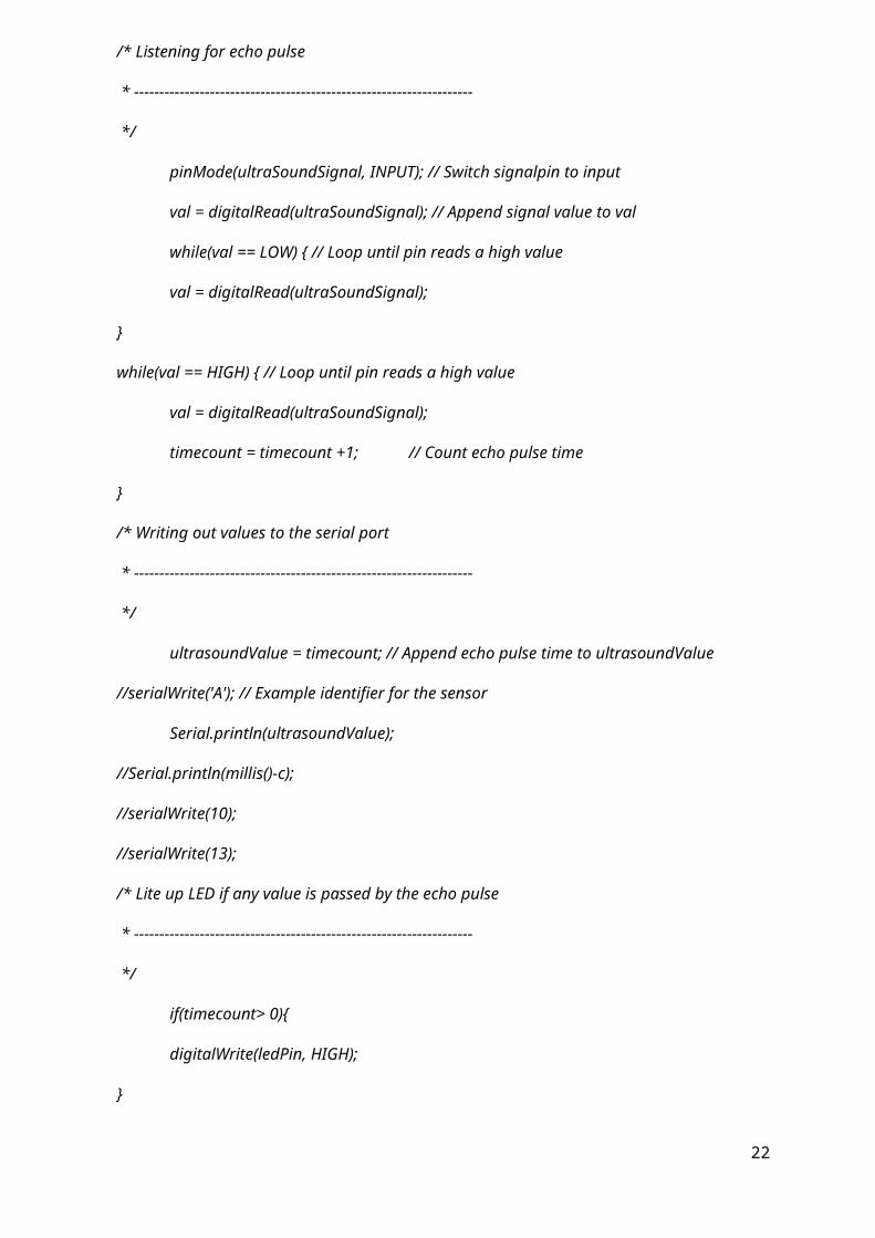
/* Listening for echo pulse
* -------------------------------------------------------------------
*/
pinMode(ultraSoundSignal, INPUT); // Switch signalpin to input
val = digitalRead(ultraSoundSignal); // Append signal value to val
while(val == LOW) { // Loop until pin reads a high value
val = digitalRead(ultraSoundSignal);
}
while(val == HIGH) { // Loop until pin reads a high value
val = digitalRead(ultraSoundSignal);
timecount = timecount +1; // Count echo pulse time
}
/* Writing out values to the serial port
* -------------------------------------------------------------------
*/
ultrasoundValue = timecount; // Append echo pulse time to ultrasoundValue
//serialWrite('A'); // Example identifier for the sensor
Serial.println(ultrasoundValue);
//Serial.println(millis()-c);
//serialWrite(10);
//serialWrite(13);
/* Lite up LED if any value is passed by the echo pulse
18

* -------------------------------------------------------------------
*/
if(timecount> 0){
digitalWrite(ledPin, HIGH);
}
/* Delay of program
* -------------------------------------------------------------------
*/
delay(100);
}
http://www.gadgetgangster.com/find-a-project/56?projectnum=361
INCREASING RANGE OF ULTRASOUND SENSOR
19

The Cyperbolic Reflector is formed in the shape of a cylindrical parabola. This shape is flat in the horizontal direction and parabolic in the vertical direction. This shape has a focus that is a line instead of the point of a circular parabolic reflector. This feature allows the separate transmitter and receiver of the ultrasound sensor bothto be at the focus of the reflector. This would not be possible if the focus were a point.
With the ultrasound sensor placed at the focus of the parabola the sound transmitted from the ultrasound sensor, which is rapidly spreading out, hits the reflector and is reflected parallel to the reflector base, no matter where it hits the reflector. This concentrates the acoustic beam in front of the reflector by greatly reducing how fast the beam spreads out vertically. This delivers more sound onto targets that are at the same level as the reflector.
In a similar way, sound returning to reflector travelling parallel to the base hits the reflector and is reflected to the focus line where the ultrasound sensor is located.This greatly increases the amount of reflected sound that hits the receiving sensor. Being flat horizontally the reflector does not change the spread of the acoustic beam in that direction. This allows the sensor to still detect objects that are off to the sides of the reflector.
To make best use of the ultrasound sensor transmitter and receiver, which both have maximum performance on their central axis, the Cyperbolic Reflector was designed with the ultrasound sensor not pointing down the axis of the parabola as is oftendone with microphone reflectors. By avoiding this configuration the ultrasound sensor does not block itself from using the optimal part of its receiver and transmitter. In addition the
20

receiver does not get any direct reflections of the transmitter off of the reflector which would cause consistent false triggers.
21
FEASIBILITY ANALYSIS
• At this time, the prototype needs a little finishing and a bit of designing before it can be launched as a product in the market. Although it works well right now, the focus should be on making the device sustainable and convenient to use.
• This project can be further improved to be able to map data with google maps if integrated with a GPS system.
FUTURE RESOURCEFULNESS
• Time: This model saves up to 50 % of the current measuring time (current system employs a person to throw a stone attached to a thread into the well and measure the length of thread manually) and 100% of the logging time, thanks to the SD card slot synced with the official log. (No need to fill out the form every single time and report to the office)
• Manpower: All this model will require is a one person to press a button and wait until the float returns back. Since the data is stored in the memory card in the required format, we only need to sync this data with the official log of the GDSA
• Accuracy: The mechatronic device is much more accurate, up to 3mm of the actual reading (only error is the minimal swing of the thread in the well).
• Wide range of applications: There is a possibility that the device could measure other properties of water i.e. potability, pH, hardness etc. so that it can be used for appropriate purposes.
22