cswip 3.1 (wis5) - print version
DESCRIPTION
CSWIP 3.1TRANSCRIPT

WORLD CENTRE FOR MATERIALS JOINING TECHNOLOGY
WELDING INSPECTION
(WIS5)
TWI Ltd, Training and Examination Services

Welding Inspection Rev 0 Jun 06 Copyright © 2006, TWI Ltd
WORLD CENTRE FOR MATERIALS JOINING TECHNOLOGY
Section 01
Typical Duties of Welding Inspectors

Welding Inspection 1.1 Rev 0 Jun 06 Visual Inspection and Typical Duties of Welding Inspectors Copyright © 2006, TWI Ltd
WORLD CENTRE FOR MATERIALS JOINING TECHNOLOGY
1.0 VISUAL INSPECTION AND TYPICAL DUTIES OF WELDING INSPECTORS
1.1 GENERAL Welding Inspectors are employed to assist with the quality control (QC) activities that are necessary to ensure that welded items will meet specified requirements and be fit for their application. For employers to have confidence in their work, Welding Inspectors need to have the ability to understand/interpret the various QC procedures and also have sound knowledge of welding technology. Visual inspection is one of the Non-Destructive Examination disciplines and for some applications may be the only form of NDE. For more demanding service conditions, visual inspection is usually followed by one or more of the other NDT techniques - surface crack detection and volumetric inspection of butt welds. Application Standards/Codes usually specify (or refer to other standards) the acceptance criteria for weld inspection and may be very specific about the particular techniques to be used for surface crack detection and volumetric inspection, they do not usually give any guidance about basic requirements for visual inspection.
Guidance and basic requirements for visual inspection are given by: BS EN 970 (Non-destructive Examination of Fusion Welds - Visual Examination) 1.2 BASIC REQUIREMENTS FOR VISUAL INSPECTION (to BS EN
970) BS EN 970 provides the following:
requirements for welding inspection personnel
recommendations about conditions suitable for visual examination
the use of gauges/inspection aids that may be needed/helpful for inspection
guidance about when inspection may be required during the stages of fabrication
guidance about information that may need to be included in the inspection
records

A summary of each of these topics is given in the following sub-sections. 1.3 WELDING INSPECTION PERSONNEL Before starting work on a particular contract, BS 970 states that Welding Inspectors should:
be familiar with relevant standards *, rules and specifications for the fabrication
work that is to be undertaken
(* standards may be National or Client)
be informed about the welding procedure(s) to be used
have good vision – in accordance with EN 473 & should be checked every 12 months
BS EN 970 does not give make any recommendation about a formal qualification for visual inspection of welds. However, it has become industry practice for inspectors to have practical experience of welding inspection together with a recognised qualification in Welding Inspection – such as a CSWIP Qualification. 1.4 CONDITIONS FOR VISUAL INSPECTION Illumination BS EN 970 states that the minimum illumination shall be 350 lux but recommends a minimum of 500 lux*. * normal shop or office lighting Access Access to the surface, for direct inspection, should enable the eye:-
to be within 600mm of the surface being inspected
to be in a position to give a viewing angle of not less than 30°
Welding Inspection 1.2 Rev 0 Jun 06 Visual Inspection and Typical Duties of Welding Inspectors Copyright © 2006, TWI Ltd
WORLD CENTRE FOR MATERIALS JOINING TECHNOLOGY
30° (min.)
600mm (max.)

Welding Inspection 1.3 Rev 0 Jun 06 Visual Inspection and Typical Duties of Welding Inspectors Copyright © 2006, TWI Ltd
WORLD CENTRE FOR MATERIALS JOINING TECHNOLOGY
1.5 AIDS TO VISUAL INSPECTION Where access is restricted for direct visual inspection, the use of a mirrored boroscope, or a fibre optic viewing system, are options that may be used - usually by agreement between the contracting parties. It may also be necessary to provide auxiliary lighting to give suitable contrast and relief effect between surface imperfections and the background. Other items of equipment that may be appropriate, to facilitate visual examination, are:
welding gauges (for checking bevel angles and weld profile, fillet sizing, measuring undercut
depth)
dedicated weld-gap gauges and linear misalignment (high-low) gauges
straight edges and measuring tapes
magnifying lens (if magnification lens used to aid visual examination it should be X2 to X5)
BS 970 has schematics of a range of welding gauges together with details of what they can be used for and the precision of the measurements that can be made. 1.6 STAGES WHEN INSPECTION MAY BE REQUIRED BS EN 970 states that examination is normally performed on welds in the as-welded condition. This means that visual inspection of the finished weld is a minimum requirement. However, BS EN 970 goes on to say that the extent of examination, and the stages when some inspection activity is required, should be specified by the Application Standard or by agreement between Client and fabricator. For fabricated items that must have high ‘integrity’, such as pressure vessels and piping or large structures inspection activity will usually be required throughout the fabrication process, namely:
before welding during welding. after welding
Inspection ‘activities’ at each of these stages of fabrication can be considered to be the ‘duties of the welding inspector’ and typical inspection checks that may be required are described in the following section.

Welding Inspection 1.4 Rev 0 Jun 06 Visual Inspection and Typical Duties of Welding Inspectors Copyright © 2006, TWI Ltd
WORLD CENTRE FOR MATERIALS JOINING TECHNOLOGY
1.7 TYPICAL DUTIES OF A WELDING INSPECTOR The relevant standards, rules and specifications that a Welding Inspector should be familiar with at the start of a new contract are all the documents he will need to refer to during the fabrication sequence in order to make judgements about particular details. Typical documents that may need to be referred to are:
the Application Standard (or Code) (for visual acceptance criteria – see note below*)
quality plans or inspection check lists (for the type & extent of inspection)
drawings (for assembly/fit-up details and dimensional requirements)
QC procedures (Company QC/QA Procedures such as those for – document control, material handling, electrode storage and issue, WPSs etc)
Note: Although most of the requirements for the fabricated item should be specified by National Standards, Client Standards or various QC Procedures, some features are not easy to define precisely and the requirement may be given as ‘to good workmanship standard’. Examples of requirements that are difficult to define precisely are some shape tolerances, distortion, surface damage or the amount of weld spatter. 'Good workmanship’ is the standard that a competent worker should be able to achieve without difficulty when using the correct tools in a particular working environment. In practice the application of the fabricated item will be the main factor that influences what is judged to be good workmanship as well as the standard that a particular fabricator has become used to satisfy particular Clients. 'Reference’ samples are sometimes needed to give guidance about the acceptance standard for details such as weld surface finish & toe blend, weld root profile and finish required for welds that need to be dressed - by grinding or linishing. A Welding Inspector should also ensure that any inspection aids that will be needed are:
in good condition calibrated - as appropriate/as specified by QC Procedures

Welding Inspection 1.5 Rev 0 Jun 06 Visual Inspection and Typical Duties of Welding Inspectors Copyright © 2006, TWI Ltd
WORLD CENTRE FOR MATERIALS JOINING TECHNOLOGY
Safety ‘consciousness’ is a duty of all employees and a Welding Inspector should:
be aware of all safety regulations for the workplace ensure that safety equipment that will be needed is available and in suitable
condition Duties Before Welding Check Action Material is in accordance with drawing/WPS is identified & can be traced to a test certificate is in suitable condition (free from damage & contamination) WPS's have been approved and are available to welders (& inspectors) Welding Equipment is in suitable condition and calibrated as appropriate Weld Preparations are in accordance with WPS (and/or drawings)
Welder Qualifications identification of welders qualified for each WPS to be used
all welder qualification certificates are valid ('in-date')
Welding Consumables those to be used are as specified by the WPSs are being stored/controlled as specified by the QC Procedure Joint Fit-ups are in accordance with WPS / Drawings
tack welds are to good workmanship standard & to Code/WPS
Weld Faces are free from defects, contamination and damage
Preheat (if required) min. temperature is in accordance with WPS Duties During Welding Check Action Site/field Welding ensure weather conditions are suitable/comply with Code
(conditions will not affect welding)
Welding Process is in accordance with WPS
Preheat (if required) min. temp. is being maintained in accordance with WPS Inter-pass Temp. max. temp. is in accordance with WPS

Welding Inspection 1.6 Rev 0 Jun 06 Visual Inspection and Typical Duties of Welding Inspectors Copyright © 2006, TWI Ltd
WORLD CENTRE FOR MATERIALS JOINING TECHNOLOGY
Welding Consumables are in accordance with WPS & being controlled as Procedure
Welding Parameters current, volts, travel speed, are in accordance with WPS Root Run is visually acceptable to Code (before filling the joint) (for single sided welds) Gouging /Grinding is by an approved method & to good workmanship standard Inter-run Cleaning is to good workmanship standard Welder is on the approval register/qualified for the WPS being used Duties After Welding Check Action Weld Identification each weld is marked with the welder's identification
each weld is identified in accordance with drawing/weld map
Weld Appearance ensure welds are suitable for all NDT (profile, cleanness
etc) visually inspect welds and sentence in accordance with Code
Dimensional Survey check dimensions are in accordance with Drawing/Code
Drawings ensure any modifications are included on 'as-built’ drawings
NDT ensure all NDT is complete & reports are available for
records
Repairs monitor in accordance with the Procedure
PWHT (if required) monitor for compliance with Procedure (check chart record)
Pressure/Load Test ensure test equipment is calibrated (if required) monitor test to ensure compliance with Procedure/Code ensure reports/records are available
Documentation Records ensure all reports/records are completed & collated as
required
Welding Inspection 1.7 Rev 0 Jun 06 Visual Inspection and Typical Duties of Welding Inspectors Copyright © 2006, TWI Ltd
WORLD CENTRE FOR MATERIALS JOINING TECHNOLOGY
1.8 EXAMINATION RECORDS The requirement for examination records/inspection reports will vary according to contract and type of fabrication and there is frequently no requirement for a formal record. When an inspection record is required it may be necessary to show that items have been checked at the specified stages and that they have satisfied the acceptance criteria. The form of this record will vary - possibly a signature against an activity on an Inspection Checklist or on a Quality Plan, or it may be an individual inspection report for each item. For individual inspection reports, BS EN 970 lists typical details for inclusion such as:
name of manufacturer/fabricator identification of item examined material type & thickness type of joint welding process acceptance standard/acceptance criteria locations and types of all imperfections not acceptable
(when specified, it may be necessary to include an accurate sketch or photo.) name of examiner/inspector and date of examination
.

Welding Inspection Rev 0 Jun 06 Copyright © 2006, TWI Ltd
WORLD CENTRE FOR MATERIALS JOINING TECHNOLOGY
Section 02
Terms & Definitions

Welding Inspection 2.1 Rev 0 Jun 06 Terms and Definitions Copyright © 2006, TWI Ltd
WORLD CENTRE FOR MATERIALS JOINING TECHNOLOGY
2.0 TERMS AND DEFINITIONS
Note: The following definitions are taken from BS 499-1:1991 “Welding terms and symbols – Glossary for welding, brazing and thermal cutting” Welding:
An operation in which two or more parts are united by means of heat or pressure or both, in such a way that there is continuity in the nature of the metal between these parts. Brazing:
A process of joining generally applied to metals in which, during or after heating, molten filler metal is drawn into or retained in the space between closely adjacent surfaces of the parts to be joined by capillary attraction. In general, the melting point of the filler metal is above 450°C but always below the melting temperature of the parent material. Braze welding:
The joining of metals using a technique similar to fusion welding and a filler metal with a lower melting point than the parent metal, but neither using capillary action as in brazing nor intentionally melting the parent metal. Weld:
A union of pieces of metal made by welding. Joint:
A connection where the individual components, suitably prepared and assembled, are joined by welding or brazing.

Type of joint Sketch Definition Butt joint
A connection between the ends or edges of two parts making an angle to one another of 135° to 180° inclusive in the region of the joint
T-joint
A connection between the end or edge of one part and the face of the other part, the parts making an angle to one another of more than 5° up to and including 90° in the region of the joint
Corner joint
a connection between the ends or edges of two parts making an angle to one another of more than 30° but less than 135° in the region of the joint
Edge joint
a connection between the edges of two parts making an angle to one another of 0° to 30° inclusive in the region of the joint
Cruciform joint
a connection in which two flat plates or two bars are welded to another flat plate at right angles and on the same axis
Lap joint
a connection between two overlapping parts making an angle to one another of 0° to 5° inclusive in the region of the weld or welds
Welding Inspection 2.2 WORLD CENTRE FOR MATERIALS JOINING TECHNOLOGY
Rev 0 Jun 06 Terms and Definitions Copyright © 2006, TWI Ltd

2.1 TYPES OF WELDS 2.1.1 FROM CONFIGURATION POINT OF VIEW
Butt weld Fillet weld
In a butt joint
In a T-joint
In a corner joint
Butt
Autogenous weld: A fusion weld made without filler metal. Can be achieved only by TIG or Oxy-fuel gas welding. Slot weld:
A joint between two overlapping components made by depositing a fillet weld round the periphery of a hole in one component so as to join it to the surface of the other component exposed through the hole.
Welding Inspection 2.3 WORLD CENTRE FOR MATERIALS JOINING TECHNOLOGY
Rev 0 Jun 06 Terms and Definitions Copyright © 2006, TWI Ltd

Plug weld:
A weld made by filling a hole in one component of a workpiece with filler metal so as to join it to the surface of an overlapping component exposed through the hole (the hole can be circular or oval).
2.1.2 FROM THE PENETRATION POINT OF VIEW
Full penetration weld:
A welded joint where the weld metal fully penetrates the joint with complete root fusion. In US the preferred term is complete joint penetration weld or CJP for short (see AWS D1.1.)
Partial penetration weld:
A welded joint without full penetration. In US the preferred term is partial joint penetration weld or PJP for short.
2.2 TYPES OF JOINTS (SEE BS EN ISO 15607) - homogeneous joint: welded joint in which the weld metal and parent material
have no significant differences in mechanical properties and/or chemical composition. Example: two carbon steel plates welded with a matching carbon steel electrode.
- heterogeneous joint: welded joint in which the weld metal and parent material
have significant differences in mechanical properties and/or chemical composition. Example: a repair weld of a cast iron item performed with a nickel base electrode.
- dissimilar joint: welded joint in which the parent materials have significant
differences in mechanical properties and/or chemical composition. Example: a carbon steel lifting lug welded onto an austenitic stainless steel pressure vessel.
Welding Inspection 2.4 WORLD CENTRE FOR MATERIALS JOINING TECHNOLOGY
Rev 0 Jun 06 Terms and Definitions Copyright © 2006, TWI Ltd

Welding Inspection 2.5 Rev 0 Jun 06 Terms and Definitions Copyright © 2006, TWI Ltd
WORLD CENTRE FOR MATERIALS JOINING TECHNOLOGY
2.3 FEATURES OF THE COMPLETED WELD - parent metal: metal to be joined or surfaced by welding, braze welding or brazing. - filler metal: metal added during welding, braze welding, brazing or surfacing. - weld metal: all metal melted during the making of a weld and retained in the weld. - heat-affected zone (HAZ): the part of the parent metal that is metallurgically
affected by the heat of welding or thermal cutting, but not melted. - fusion line: the boundary between the weld metal and the HAZ in a fusion weld.
This is a non-standard term for weld junction. - weld zone: the zone containing the weld metal and the HAZ. - weld face: the surface of a fusion weld exposed on the side from which the weld
has been made. - root: the zone on the side of the first run farthest from the welder. - toe: the boundary between a weld face and the parent metal or between runs. This
is a very important feature of a weld since toes are points of high stress concentration and often they are initiation points for different types of cracks (e.g. fatigue cracks, cold cracks). In order to reduce the stress concentration, toes must blend smoothly into the parent metal surface.
- excess weld metal: weld metal lying outside the plane joining the toes. Other non-
standard terms for this feature: reinforcement, overfill.

Welding Inspection 2.6 Rev 0 Jun 06 Terms and Definitions Copyright © 2006, TWI Ltd
WORLD CENTRE FOR MATERIALS JOINING TECHNOLOGY
2.4 WELD PREPARATION A preparation for making a connection where the individual components, suitably prepared and assembled, are joined by welding or brazing.
Fusion line
Weld metal
Root
Parent metal
HAZ
Weld zone
Weld face
Toe
Parent metal
Excess weld metal
Root
Parent metal
Weld metal
HAZ
Weld zone Weld
Toe face
Parent metal
Fusion line
Excess weld metal
Excess weld metal

Welding Inspection 2.7 Rev 0 Jun 06 Terms and Definitions Copyright © 2006, TWI Ltd
WORLD CENTRE FOR MATERIALS JOINING TECHNOLOGY
2.4.1 FEATURES OF THE WELD PREPARATION - angle of bevel: the angle at which the edge of a component is prepared for
making a weld. In case of a V preparation for a MMA weld on carbon steel plates, this angle is 30°. In case of a U preparation for a MMA weld on carbon steel plates, this angle is between 8-12°. In case of a single bevel preparation for a MMA weld on carbon steel plates, this angle is 50°. In case of a single J preparation for a MMA weld on carbon steel plates, this angle is between 10-20°.
- included angle: the angle between the planes of the fusion faces of parts to be
welded. In case of single V, single U, double V and double U this angle is twice the bevel angle. In case of single bevel, single J, double bevel and double J, the included angle is equal to the bevel angle.
- root face: the portion of a fusion face at the root that is not bevelled or grooved.
It’s value depends on the welding process used, parent material to be welded and application; for a full penetration weld on carbon steel plates, it has a value between 1-2 mm.
- gap: the minimum distance at any cross section between edges, ends or surfaces
to be joined. Its value depends on the welding process used and application; for a full penetration weld on carbon steel plates, it has a value between 1-4 mm.
- root radius: the radius of the curved portion of the fusion face in a component
prepared for a single J, single U, double J or double U weld. In case of MMA, MIG/MAG and oxyfuel gas welding on carbon steel plates, the root radius has a value of 6mm in case of single and double U preparations and 8 mm in case of single and double J preparations.
- land: the straight portion of a fusion face between the root face and the curved
part of a J or U preparation. Can be 0. Usually present in case of weld preparations for MIG welding of aluminium alloys.

2.4.2 TYPES OF PREPARATION
Open square butt preparation This preparation is used for welding thin components, either from one side or
both sides. If the root gap is zero (i.e. if components are in contact), this preparation becomes a closed square butt preparation (unrecommended due to the lack of penetration problems!
Included angle
Welding Inspection 2.8 Rev 0 Jun 06 Terms and Definitions Copyright © 2006, TWI Ltd
WORLD CENTRE FOR MATERIALS JOINING TECHNOLOGY
Angle of bevel
Root Face Gap
Single V preparation The V preparation is one of the most common preparations used in welding; it
can be produced using flame or plasma cutting (cheap and fast). For thicker plates a double V preparation is preferred since it requires less filler material to complete the joint and the residual stresses can be balanced on both sides of the joint resulting in lower angular distortion.
Double V preparation The depth of preparation can be the same on both sides (symmetric double V
preparation) or the depth of preparation can be deeper on one side compared with the opposite side (asymmetric double V preparation). Usually, in this situation the depth of preparation is distributed as 1/3 of the thickness of the plate on one side vs. the remaining 2/3 on the backside. This asymmetric preparation allows for a balanced
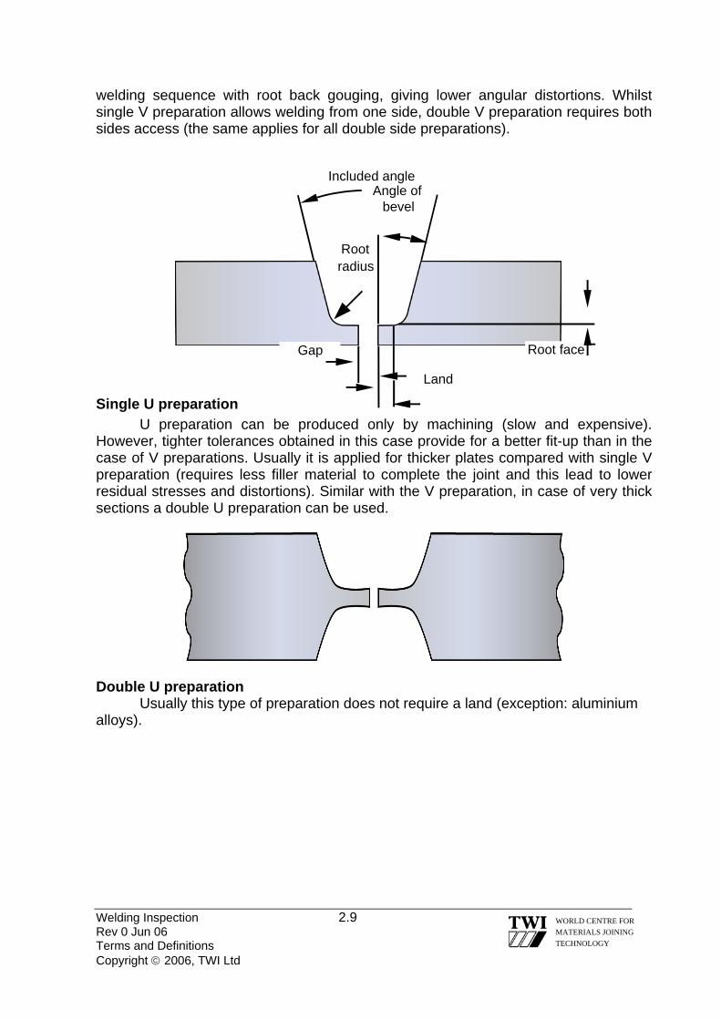
welding sequence with root back gouging, giving lower angular distortions. Whilst single V preparation allows welding from one side, double V preparation requires both sides access (the same applies for all double side preparations).
Welding Inspection 2.9 Rev 0 Jun 06 Terms and Definitions Copyright © 2006, TWI Ltd
WORLD CENTRE FOR MATERIALS JOINING TECHNOLOGY
Single U preparation U preparation can be produced only by machining (slow and expensive).
However, tighter tolerances obtained in this case provide for a better fit-up than in the case of V preparations. Usually it is applied for thicker plates compared with single V preparation (requires less filler material to complete the joint and this lead to lower residual stresses and distortions). Similar with the V preparation, in case of very thick sections a double U preparation can be used.
Gap
Land
Root face
Rootradius
Included angle Angle of
bevel
Double U preparation
Usually this type of preparation does not require a land (exception: aluminium alloys).

Single V preparation with backing strip
The backing strip is made out of the same type of material as the parent material. The thickness of this backing strip is minimum 6 mm. It allows the production of full penetration welds with increased current and hence increased deposition rates/productivity without the danger of burn-through. Usually, the backing strip is tack welded on the backside of one component using a fillet weld. The main problems related with this type of weld are poor fatigue resistance and the probability of crevice corrosion between the parent metal and the backing strip. It is also difficult to examine by NDT due to the built-in crevice at the root of the joint. Note that in this case there is no root face!
Welding Inspection 2.10 Rev 0 Jun 06 Terms and Definitions Copyright © 2006, TWI Ltd
WORLD CENTRE FOR MATERIALS JOINING TECHNOLOGY
Single bevel preparation
Double bevel preparation

Single J preparation
Double J preparation
All these preparations (single/double bevel and single/double J) can be used on T joints as well. Double preparations are recommended in case of thick sections. The main advantage of these preparations is that only one component is prepared (cheap, can allow for small misalignments).
For further details regarding weld preparations, please refer to BS EN ISO 9692 standard. 2.5 SIZE OF BUTT WELDS - full penetration butt weld
Actual throat thickness
Design throat thickness
Welding Inspection 2.11 WORLD CENTRE FOR MATERIALS JOINING TECHNOLOGY
Rev 0 Jun 06 Terms and Definitions Copyright © 2006, TWI Ltd
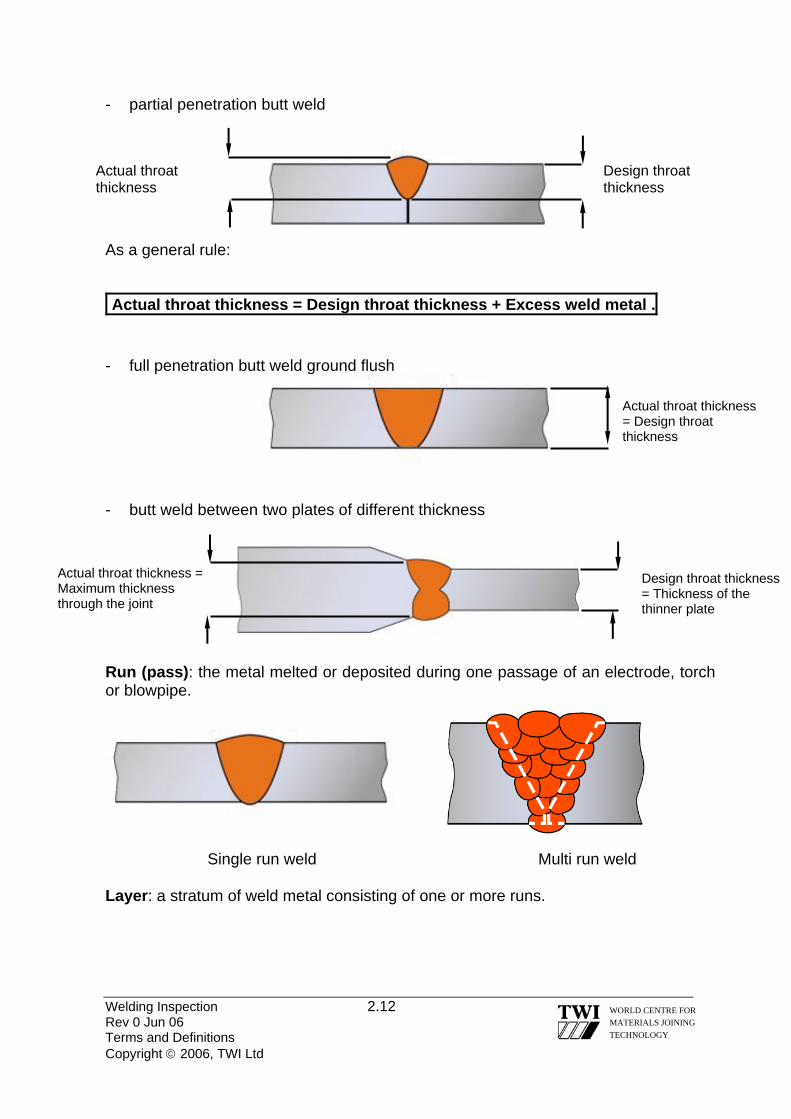
- partial penetration butt weld
As a general rule:
Actual throat thickness = Design throat thickness + Excess weld metal . - full penetration butt weld ground flush
- butt weld between two plates of different thickness
Actual throat thickness = Design throat thickness
Design throat thickness
Actual throat thickness
Actual throat thickness = Maximum thickness through the joint
Design throat thickness = Thickness of the thinner plate
Run (pass): the metal melted or deposited during one passage of an electrode, torch or blowpipe.
Single run weld Multi run weld Layer: a stratum of weld metal consisting of one or more runs.
Welding Inspection 2.12 WORLD CENTRE FOR MATERIALS JOINING TECHNOLOGY
Rev 0 Jun 06 Terms and Definitions Copyright © 2006, TWI Ltd

Types of butt weld (from accessibility point of view):
Single side weld Double side weld 2.6 FILLET WELD A fusion weld, other than a butt, edge or fusion spot weld, which is approximately triangular in transverse cross section. 2.6.1 SIZE OF FILLET WELDS Unlike butt welds, fillet welds can be defined using several dimensions. - actual throat thickness: the perpendicular distance between two lines, each
parallel to a line joining the outer toes, one being a tangent at the weld face and the other being through the furthermost point of fusion penetration
- design throat thickness: the minimum dimension of throat thickness used for
purposes of design. Also known as effective throat thickness. Symbolised on the drawing with “a”.
- leg length: the distance from the actual or projected intersection of the fusion
faces and the toe of a fillet weld, measured across the fusion face. Symbolised on the drawing with “z”.
Welding Inspection 2.13 Rev 0 Jun 06 Terms and Definitions Copyright © 2006, TWI Ltd
WORLD CENTRE FOR MATERIALS JOINING TECHNOLOGY
Leg length
Actual throat thickness
Design throat thickness
Leg length

2.6.2 SHAPE OF FILLET WELDS - mitre fillet weld: a flat face fillet weld in which the leg lengths are equal within the
agreed tolerance. The cross section area of this type of weld is considered to be a right angle isosceles triangle with a design throat thickness “a” and a leg length “z”. The relation between design throat thickness and leg length is:
a = 0,707 × z . or z = 1,41 × a .
- convex fillet weld: a fillet weld in which the weld face is convex. The above
relation between the leg length and the design throat thickness written in case of mitre fillet welds is also valid for this type of weld. Since there is an excess weld metal present in this case, the actual throat thickness is bigger than the design throat thickness.
- concave fillet weld: a fillet weld in which the weld face is concave. The above
relation between the leg length and the design throat thickness written in case of mitre fillet welds is not anymore valid for this type of weld. Also, the design throat thickness is equal to the actual throat thickness. Due to the smooth blending between the weld face and the surrounding parent material, the stress concentration effect at the toes of the weld is reduced compared with the previous type. This is why this type of weld is highly desired in case of applications subjected to cyclic loads where fatigue phenomena might be a major cause for failure.
Welding Inspection 2.14 WORLD CENTRE FOR MATERIALS JOINING TECHNOLOGY
Rev 0 Jun 06 Terms and Definitions Copyright © 2006, TWI Ltd

- asymmetrical fillet weld: a fillet weld in which the vertical leg length is not equal
with the horizontal leg length. . The relation between the leg length and the design throat thickness written in case of mitre fillet welds is not anymore valid for this type of weld because the cross section is not anymore an isosceles triangle.
Welding Inspection 2.15 Rev 0 Jun 06 Terms and Definitions Copyright © 2006, TWI Ltd
WORLD CENTRE FOR MATERIALS JOINING TECHNOLOGY
Vertical leg size
Horizontal leg size
Throat size
- deep penetration fillet weld: a fillet weld with a deeper than normal penetration. It
is produced using high heat input welding processes (i.e. SAW or MAG with spray transfer). This type of weld uses the benefits of greater arc penetration to obtain the required throat thickness whilst reducing the amount of deposited metal needed, thus leading to a reduction in residual stress level. In order to produce a consistent and constant penetration, the travel speed must be kept constant, at a high value. As a consequence, this type of weld is usually produced using mechanised or automatic welding processes. Also, the high depth-to-width ratio increases the probability of solidification centreline cracking. In order to differentiate this type of welds from the previous types, the throat thickness is symbolised with “s” instead of “a”.

2.6.3 COMPOUND OF BUTT AND FILLET WELDS A combination of butt and fillet welds used in case of T joints with full or partial penetration or butt joints between two plates with different thickness. Fillet welds added on top of the groove welds improve the blending of weld face towards parent metal surface and reduce the stress concentration at the toes of the weld.
Welding Inspection 2.16 Rev 0 Jun 06 Terms and Definitions Copyright © 2006, TWI Ltd
WORLD CENTRE FOR MATERIALS JOINING TECHNOLOGY
Double bevel compound weld 2.7 WELDING POSITION, WELD SLOPE AND WELD ROTATION
Weld position - the orientation of a weld expressed in terms of working position, weld slope and weld rotation (for further details, please see ISO 6947). Weld slope –the angle between root line and the positive X-axis of the horizontal reference plane, measured in mathematically positive direction (i.e. counter-clockwise).
Weld rotation – the angle between the centreline of the weld and the positive Z-axis or a line parallel to the Y-axis, measured in the mathematically positive direction (i.e. counter-clockwise) in the plane of the transverse cross section of the weld in question.
Bevel weld Fillet
weld
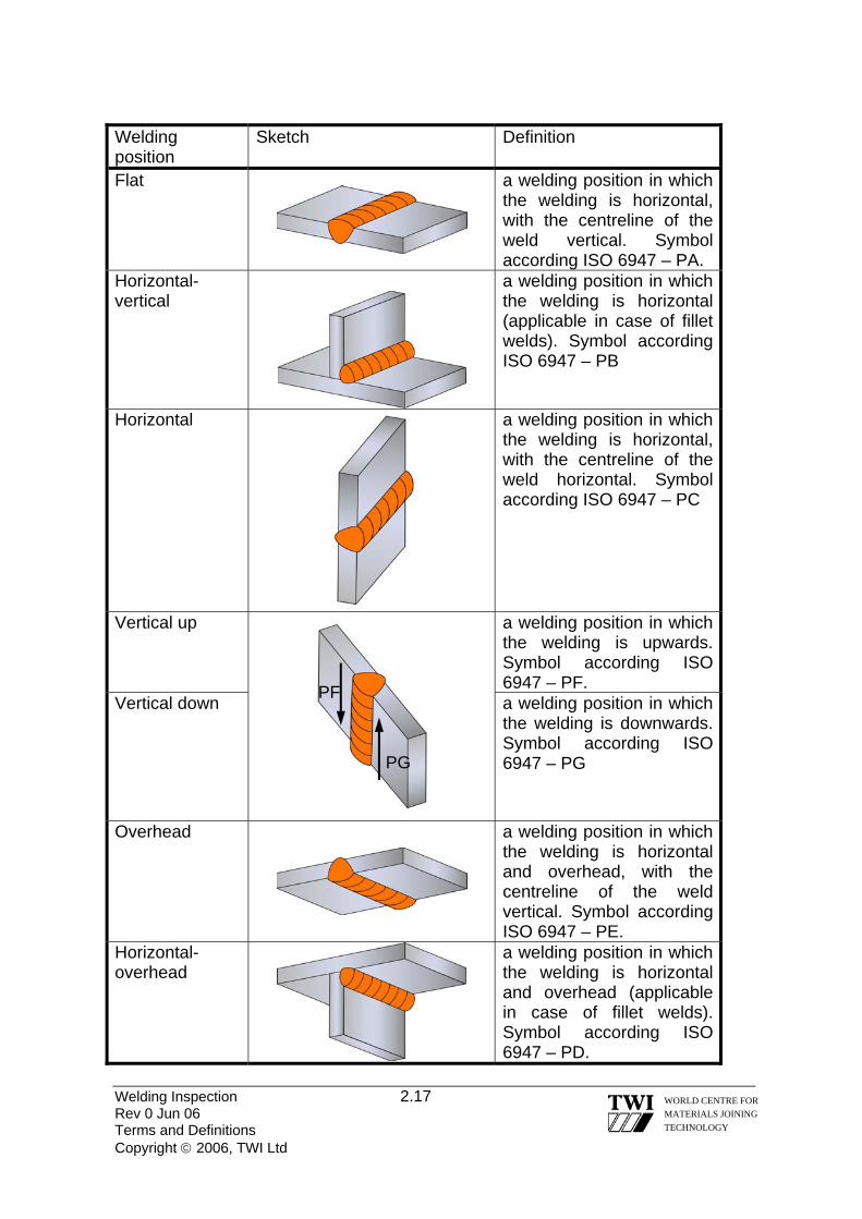
Welding position
Sketch Definition
Flat
a welding position in which the welding is horizontal, with the centreline of the weld vertical. Symbol according ISO 6947 – PA.
Horizontal-vertical
a welding position in which the welding is horizontal (applicable in case of fillet welds). Symbol according ISO 6947 – PB
Horizontal a welding position in which the welding is horizontal, with the centreline of the weld horizontal. Symbol according ISO 6947 – PC
Vertical up a welding position in which the welding is upwards. Symbol according ISO 6947 – PF.
Vertical down a welding position in which the welding is downwards. Symbol according ISO 6947 – PG
Overhead
a welding position in which the welding is horizontal and overhead, with the centreline of the weld vertical. Symbol according ISO 6947 – PE.
Horizontal-overhead
a welding position in which the welding is horizontal and overhead (applicable in case of fillet welds). Symbol according ISO 6947 – PD.
PG
PF
Welding Inspection 2.17 WORLD CENTRE FOR MATERIALS JOINING TECHNOLOGY
Rev 0 Jun 06 Terms and Definitions Copyright © 2006, TWI Ltd
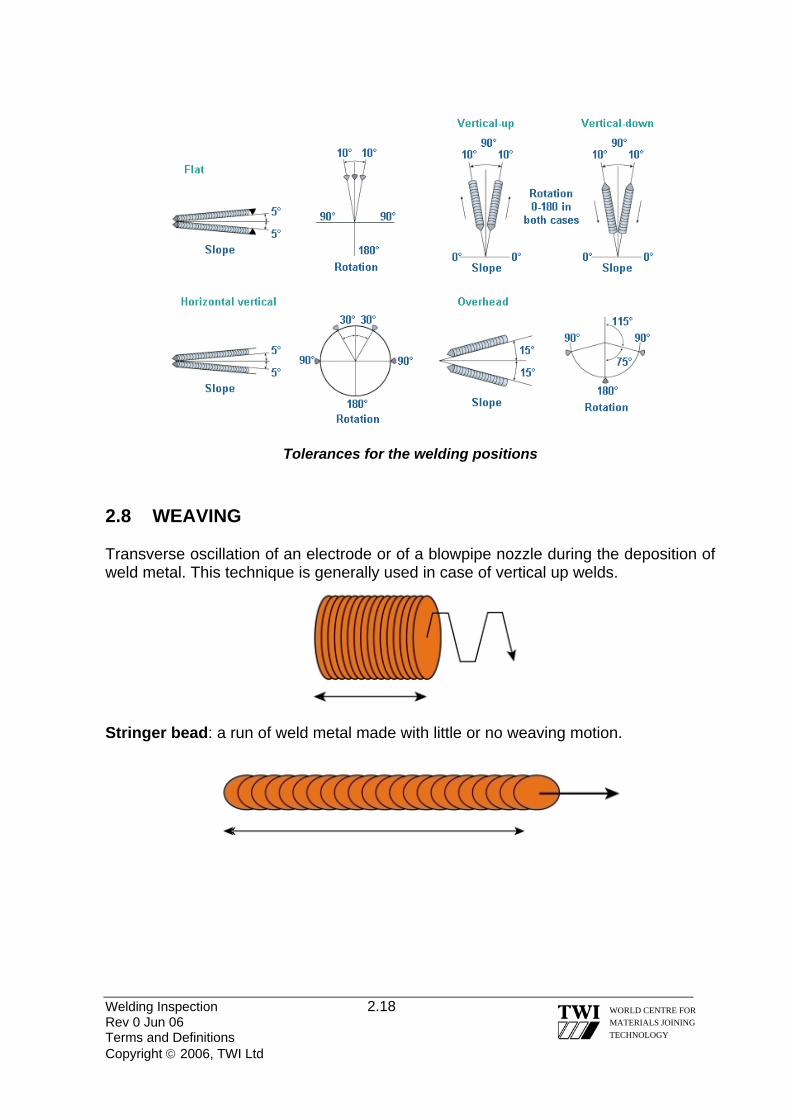
Tolerances for the welding positions
2.8 WEAVING Transverse oscillation of an electrode or of a blowpipe nozzle during the deposition of weld metal. This technique is generally used in case of vertical up welds.
Stringer bead: a run of weld metal made with little or no weaving motion.
Welding Inspection 2.18 WORLD CENTRE FOR MATERIALS JOINING TECHNOLOGY
Rev 0 Jun 06 Terms and Definitions Copyright © 2006, TWI Ltd

Welding Inspection Rev 0 Jun 06 Copyright © 2006, TWI Ltd
WORLD CENTRE FOR MATERIALS JOINING TECHNOLOGY
Section 03
Welding Imperfections

Welding Inspection 3.1 Rev 0 Jun 06 Welding Imperfections Copyright © 2006, TWI Ltd
WORLD CENTRE FOR MATERIALS JOINING TECHNOLOGY
3.0 WELDING IMPERFECTIONS 3.1 DEFINITIONS Definitions (see BS EN ISO 6520-1) Imperfection: any deviation from the ideal weld. Defect: an unacceptable imperfection. Classification of imperfections according to BS EN ISO 6520-1:
This standard classifies the geometric imperfections in case of fusion welding, dividing them into six groups: 1) Cracks 2) Cavities 3) Solid inclusions 4) Lack of fusion and penetration 5) Imperfect shape and dimension 6) Miscellaneous imperfections
It is important that an imperfection is correctly identified thus allowing for the cause to be identified and actions taken to prevent further occurrence. 3.2 CRACKS Definition: an imperfection produced by a local rupture in the solid state, which may arise from the effect of cooling or stresses. Cracks are more significant than other types of imperfection, as their geometry produces a very large stress concentration at the crack tip, making them more likely to cause fracture. Types of cracks: - longitudinal cracks - transverse cracks - radiating cracks (cracks radiating from a common point) - crater cracks - branching cracks (a group of connected cracks originating from a common crack) These cracks can be situated: - in the weld metal - in the HAZ - in the parent metal Exception: Crater cracks are found only in the weld metal.

Depending on their nature, these cracks can be: - hot cracks (i.e. solidification cracks liquation cracks) - precipitation induced cracks (i.e. reheat cracks, present in creep resisting steels) - cold cracks (i.e. hydrogen induced cracks) - lamellar tearing
3.2.1 HOT CRACKS Depending on their location and mode of occurrence, hot cracks can be: - solidification cracks: occur in the weld metal (usually along the centreline of the
weld) as a result of the solidification process - liquation cracks: occur in the coarse grain HAZ, in the near vicinity of the fusion
line as a result of heating the material to an elevated temperature, high enough to produce liquation of the low melting point constituents placed on grain boundaries.
3.2.2 SOLIDIFICATION CRACKS
Generally, solidification cracking can occur when: • the weld metal has a high carbon or impurity (sulphur etc) element
content • the depth-to-width ratio of the solidifying weld bead is large (deep &
narrow) • disruption of the heat flow condition occurs, e.g. stop/start condition
The cracks can be wide and open to the surface like shrinkage voids or sub-surface and possibly narrow.
Solidification cracking is most likely to occur in compositions, which result in a wide freezing temperature range. In steels this is commonly created by a higher than Welding Inspection 3.2 Rev 0 Jun 06 Welding Imperfections Copyright © 2006, TWI Ltd
WORLD CENTRE FOR MATERIALS JOINING TECHNOLOGY
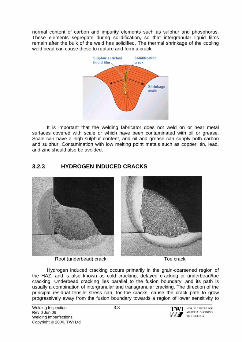
normal content of carbon and impurity elements such as sulphur and phosphorus. These elements segregate during solidification, so that intergranular liquid films remain after the bulk of the weld has solidified. The thermal shrinkage of the cooling weld bead can cause these to rupture and form a crack.
It is important that the welding fabricator does not weld on or near metal
surfaces covered with scale or which have been contaminated with oil or grease. Scale can have a high sulphur content, and oil and grease can supply both carbon and sulphur. Contamination with low melting point metals such as copper, tin, lead, and zinc should also be avoided.
3.2.3 HYDROGEN INDUCED CRACKS
Root (underbead) crack Toe crack
Hydrogen induced cracking occurs primarily in the grain-coarsened region of the HAZ, and is also known as cold cracking, delayed cracking or underbead/toe cracking. Underbead cracking lies parallel to the fusion boundary, and its path is usually a combination of intergranular and transgranular cracking. The direction of the principal residual tensile stress can, for toe cracks, cause the crack path to grow progressively away from the fusion boundary towards a region of lower sensitivity to
Welding Inspection 3.3 Rev 0 Jun 06 Welding Imperfections Copyright © 2006, TWI Ltd
WORLD CENTRE FOR MATERIALS JOINING TECHNOLOGY

hydrogen cracking. When this happens, the crack growth rate decreases and eventually arrests.
A combination of three factors is necessary to cause HAZ hydrogen cracking:
In addition, the weld must cool down to near normal ambient temperature, where
the effect of hydrogen is at its maximum. If any one factor is not satisfied, cracking is prevented. Therefore, cracking can be avoided through control of one or more of these factors.
• apply preheat (to slow down the cooling rate and thus avoid the formation of
susceptible microstructures) • maintain a specific interpass temperature (same effect as preheat) • postheat on completion of welding (to reduce the hydrogen content by allowing
hydrogen to effuse from the weld area) • apply PWHT (to reduce residual stress and eliminate susceptible
microstructures) • reduce weld metal hydrogen by proper selection of welding
process/consumable (e.g. use TIG welding instead MMA, use basic covered electrodes instead cellulose ones)
• use multi-run instead single-run technique (eliminate susceptible microstructures by means of self tempering effect, reduce the hydrogen content by allowing hydrogen to effuse from the weld area)
• use a temper bead or hot pass technique (same effect as above) • use austenitic or nickel filler (avoid susceptible microstructure formation and
allow hydrogen diffusion out of critical areas) • use dry shielding gases (reduce hydrogen content) • clean joint from rust (avoid hydrogen contamination from moisture present in
the rust) • reduce residual stress • blend the weld profile (reduce stress concentration at the toes of the weld)
Welding Inspection 3.4 Rev 0 Jun 06 Welding Imperfections Copyright © 2006, TWI Ltd
WORLD CENTRE FOR MATERIALS JOINING TECHNOLOGY

3.2.4 LAMELLAR TEARING
Lamellar tearing occurs only in rolled steel products (primarily plates) and its main distinguishing feature is that the cracking has a terraced appearance. Cracking occurs in joints where: • a thermal contraction strain occurs in the through thickness direction of steel
plate • non-metallic inclusions are present as very thin platelets, with their principal
planes parallel to the plate surface
Contraction strain imposed on the planar non-metallic inclusions results in progressive decohesion to form the roughly rectangular holes which are the horizontal parts of the cracking, parallel to the plate surface. With further strain, the vertical parts of the cracking are produced, generally by ductile shear cracking. These two stages create the terraced appearance of these cracks.
Two main options are available to control the problem in welded joints liable to lamellar tearing: • use a clean steel with guaranteed through-thickness properties (Z grade) • a combination of joint design, restraint control and welding sequence to minimise the risk of cracking. Welding Inspection 3.5 Rev 0 Jun 06 Welding Imperfections Copyright © 2006, TWI Ltd
WORLD CENTRE FOR MATERIALS JOINING TECHNOLOGY
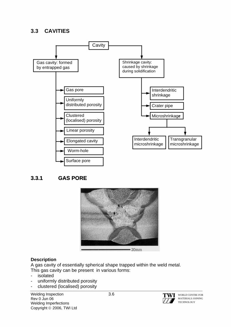
3.3 CAVITIES Cavity
Shrinkage cavity: caused by shrinkage during solidification
Gas cavity: formed by entrapped gas
Gas pore
Uniformly distributed porosity
Clustered (localised) porosity
Linear porosity
Elongated cavity
Worm-hole
Welding Inspection 3.6 Rev 0 Jun 06 Welding Imperfections Copyright © 2006, TWI Ltd
WORLD CENTRE FOR MATERIALS JOINING TECHNOLOGY
Surface pore
Interdendritic microshrinkage
Transgranular microshrinkage
Interdendritic shrinkage
Crater pipe
Microshrinkage
3.3.1 GAS PORE 3.3.1 GAS PORE
Description A gas cavity of essentially spherical shape trapped within the weld metal. This gas cavity can be present in various forms: - isolated - uniformly distributed porosity - clustered (localised) porosity

- linear porosity - elongated cavity - surface pore Causes Prevention Damp fluxes/corroded electrode (MMA)
Use dry electrodes in good condition
Grease/hydrocarbon/water contamination of prepared surface
Clean prepared surface
Air entrapment in gas shield (MIG/MAG TIG)
Check hose connections
Incorrect/insufficient deoxidant in electrode, filler or parent metal
Use electrode with sufficient deoxidation activity
Too high an arc voltage or arc length Reduce voltage and arc length Gas evolution from priming paints/surface treatment
Identify risk of reaction before surface treatment is applied
Too high of a shielding gas flow rate which results in turbulence (MIG/MAG TIG)
Optimise gas flow rate
Comments Note that porosity can either be localised or finely dispersed voids throughout the weld metal.
3.3.2 WORM HOLES
Description Elongated or tubular cavities formed by entrapped gas during the solidification of the weld metal; they can occur singly or in groups. Welding Inspection 3.7 Rev 0 Jun 06 Welding Imperfections Copyright © 2006, TWI Ltd
WORLD CENTRE FOR MATERIALS JOINING TECHNOLOGY

Causes Prevention Gross contaminated of preparation surface
Introduce preweld cleaning procedures
Laminated work surface Replace parent material with an unlaminated piece
Crevices in work surface due to joint geometry
Eliminate joint shapes which produce crevices
Comments Wormholes are caused by the progressive entrapment of gas between the solidifying metal crystals (dendrites) producing characteristic elongated pores of circular cross-section. These elongated pores can appear as a “herring-bone” array on a radiograph. Some of them may break the surface of the weld.
3.3.3 SURFACE POROSITY
Description A gas pore that breaks the surface of the weld. Causes Prevention Damp or contaminated surface or electrode
Clean surface and dry electrodes
Low fluxing activity (MIG/MAG) Use a high activity flux Excess sulphur (particularly free-cutting steels) producing sulphur dioxide
Use high manganese electrode to produce MnS, note free-cutting steels (high sulphur) should not normally be welded
Loss of shielding gas due to long arc or high breezes (MIG/MAG)
Improve screening against draughts and reduce arc length
Too high of a shielding gas flow rate which results in turbulence (MIG/MAG TIG)
Optimise gas flow rate
Welding Inspection 3.8 Rev 0 Jun 06 Welding Imperfections Copyright © 2006, TWI Ltd
WORLD CENTRE FOR MATERIALS JOINING TECHNOLOGY

Comments The origins of surface porosity are similar to those for uniform porosity.
3.3.4 CRATER PIPE
Description A shrinkage cavity at the end of a weld run. The main cause is shrinkage during solidification. Causes Prevention Lack of welder skill due to using processes with too high a current
Retrain welder
Inoperative crater filler (Slope out) (TIG)
Use correct crater filling techniques
Comments Crater filling is a particular problem in TIG welding due to its low heat input. To fill the crater for this process it is necessary to reduce the weld current (slope out) in a series of descending steps until the arc is extinguished.
Welding Inspection 3.9 Rev 0 Jun 06 Welding Imperfections Copyright © 2006, TWI Ltd
WORLD CENTRE FOR MATERIALS JOINING TECHNOLOGY

3.4 SOLID INCLUSIONS LUSIONS Definition: Definition: Solid foreign substances entrapped in the weld metal. Solid foreign substances entrapped in the weld metal.
Solid inclusions
Welding Inspection 3.10 Rev 0 Jun 06 Welding Imperfections Copyright © 2006, TWI Ltd
WORLD CENTRE FOR MATERIALS JOINING TECHNOLOGY
Oxide inclusion
Metallic inclusion
Flux inclusion
Slag inclusion
3.4.1 SLAG INCLUSIONS 3.4.1 SLAG INCLUSIONS
Description Slag trapped during welding. The imperfection is of an irregular shape and thus differs in appearance from a gas pore.
ClusteredIsolated
Tungsten
Linear Other metal
Copper
Welding Inspection 3.11 Rev 0 Jun 06 Welding Imperfections Copyright © 2006, TWI Ltd
WORLD CENTRE FOR MATERIALS JOINING TECHNOLOGY
Causes Prevention Incomplete slag removal from underlying surface of multipass weld
Improve inter-run slag removal
Slag flooding ahead of arc Position work to gain control of slag. Welder needs to correct electrode angle
Entrapment of slag in work surface Dress work surface smooth Comments A fine dispersion of inclusions may be present within the weld metal, particularly if the MMA process is used. These only become a problem when large or sharp-edged inclusions are produced.
3.4.2 FLUX INCLUSIONS
Description Flux trapped during welding. The imperfection is of an irregular shape and thus differs in appearance from a gas pore. Appear only in case of flux associated welding processes (i.e. MMA, SAW and FCAW). Causes Prevention Unfused flux due to damaged coating Use electrodes in good condition Flux fails to melt and becomes trapped in the weld (SAW or FCAW)
Change the flux/wire. Adjust welding parameters i.e. current, voltage etc to produce satisfactory welding conditions
3.4.3 OXIDE INCLUSIONS Description Oxides trapped during welding. The imperfection is of an irregular shape and thus differs in appearance from a gas pore. Causes Prevention Heavy mill scale/rust on work surface Grind surface prior to welding Comments A special type of oxide inclusion is puckering. This type of defect occurs especially in the case of aluminium alloys. Gross oxide film enfoldment can occur due to a combination of unsatisfactory protection from atmospheric contamination and turbulence in the weld pool.

3.4.4 TUNGSTEN INCLUSIONS
Description Particles of tungsten can become embedded during TIG welding. This imperfection appears as a light area on radiographs due to the fact that tungsten is denser than the surrounding metal and absorbs larger amounts of X/gamma radiation. Causes Prevention Contact of electrode tip with weld pool Keep tungsten out of weld pool; use
HF start Contact of filler metal with hot tip of electrode
Avoid contact between electrode and filler metal
Contamination of the electrode tip by spatter from the weld pool
Reduce welding current; adjust shielding gas flow rate
Exceeding the current limit for a given electrode size or type
Reduce welding current; replace electrode with a larger diameter one
Extension of electrode beyond the normal distance from the collet, resulting in overheating of the electrode
Reduce electrode extension and/or welding current
Inadequate tightening of the collet Tighten the collet Inadequate shielding gas flow rate or excessive wind drafts resulting in oxidation of the electrode tip
Adjust the shielding gas flow rate; protect the weld area; ensure that the post gas flow after stopping the arc continues for at least 5 seconds
Splits or cracks in the electrode Change the electrode, ensure the correct size tungsten is selected for the given welding current used
Inadequate shielding gas (e.g. use of argon-oxygen or argon-carbon dioxide mixtures that are used for MAG welding)
Change to correct gas composition
Welding Inspection 3.12 Rev 0 Jun 06 Welding Imperfections Copyright © 2006, TWI Ltd
WORLD CENTRE FOR MATERIALS JOINING TECHNOLOGY

3.5 LACK OF FUSION AND PENETRATION OF FUSION AND PENETRATION 3.5.1 LACK OF FUSION 3.5.1 LACK OF FUSION
Definition: Definition: Lack of union between the weld metal and the parent metal or between the successive layers of weld metal. Lack of union between the weld metal and the parent metal or between the successive layers of weld metal. Lack of
fusion
Lack of inter-run fusion
Lack of sidewall fusion
Lack of root fusion
3.5.1.1 LACK OF SIDEWALL FUSION 3.5.1.1 LACK OF SIDEWALL FUSION
Description Lack of union between the weld and parent metal at one or both sides of the weld. Causes Prevention Low heat input to weld Increase arc voltage and/or welding current;
decrease travel speed Molten metal flooding ahead of arc Improve electrode angle and work position;
increase travel speed
Oxide or scale on weld preparation Improve edge preparation procedure
Excessive inductance in MAG dip transfer welding
Reduce inductance, even if this increases spatter
Welding Inspection 3.13 Rev 0 Jun 06 Welding Imperfections Copyright © 2006, TWI Ltd
WORLD CENTRE FOR MATERIALS JOINING TECHNOLOGY

Comments During welding sufficient heat must be available at the edge of the weld pool to produce fusion with the parent metal.
3.5.1.2 LACK OF INTER-RUN FUSION
Description A lack of union along the fusion line, between the weld beads. Causes Prevention Low arc current resulting in low fluidity of weld pool
Increase current
Too high a travel speed Reduce travel speed Inaccurate bead placement Retrain welder Comments Lack of inter-run fusion produce crevices between the weld beads and cause local entrapment of slag.
Welding Inspection 3.14 Rev 0 Jun 06 Welding Imperfections Copyright © 2006, TWI Ltd
WORLD CENTRE FOR MATERIALS JOINING TECHNOLOGY

3.5.1.3 LACK OF ROOT FUSION
Welding Inspection 3.15 Rev 0 Jun 06 Welding Imperfections Copyright © 2006, TWI Ltd
WORLD CENTRE FOR MATERIALS JOINING TECHNOLOGY
Description Lack of fusion between the weld and parent metal at the root of a weld. Causes Prevention Low heat input Increase welding current and/or arc voltage;
decrease travel speed Excessive inductance in MAG dip transfer welding,
Use correct induction setting for the parent metal thickness
MMA electrode too large (low current density)
Reduce electrode size
Use of vertical down welding Switch to vertical up procedure Large root face Reduce root face Small root gap Ensure correct root opening Incorrect angle or incorrect electrode manipulation
Use correct electrode angle. Ensure welder is fully qualified and competent
Excessive misalignment at root Ensure correct alignment 3.5.2 LACK OF PENETRATION
Lack of penetration
Incomplete
penetration Incomplete root
penetration

3.5.2.1 INCOMPLETE PENETRATION
Description The difference between the actual and nominal penetration. Causes Prevention Excessively thick root face, insufficient root gap or failure to cut back to sound metal in a “back gouging” operation
Improve back gouging technique and ensure the edge preparation is as per approved WPS
Low heat input Increase welding current and/or arc voltage; decrease travel speed
Excessive inductance in MAG dip transfer welding, pool flooding ahead of arc
Improve electrical settings and possibly switch to spray arc transfer
MMA electrode too large (low current density)
Reduce electrode size
Use of vertical down welding Switch to vertical up procedure Comments If the weld joint is not of a critical nature, i.e. the required strength is low and the area is not prone to fatigue cracking, it is possible to produce a partial penetration weld. In this case incomplete root penetration is considered part of this structure and is not an imperfection (this would normally be determined by the design or code requirement).
Welding Inspection 3.16 Rev 0 Jun 06 Welding Imperfections Copyright © 2006, TWI Ltd
WORLD CENTRE FOR MATERIALS JOINING TECHNOLOGY

3.5.2.2 INCOMPLETE ROOT PENETRATION
Description One or both fusion faces of the root are not melted. When examined from the root side, you can clearly see one or both of the root edges unmelted. Causes and prevention Same as for lack of root fusion.
Welding Inspection 3.17 Rev 0 Jun 06 Welding Imperfections Copyright © 2006, TWI Ltd
WORLD CENTRE FOR MATERIALS JOINING TECHNOLOGY

3.6 IMPERFECT SHAPE AND DIMENSIONS
3.6.1 UNDERCUT
Description An irregular groove at the toe of a run in the parent metal or in a previously deposited weld metal due to welding. It is characterised by its depth, length and sharpness. Undercut
Intermittent undercut
Continuous undercut
Inter run undercut
Causes Prevention Melting of top edge due to high welding current (especially at free edge) or high travel speed
Reduce power input, especially approaching a free edge where overheating can occur
Attempting a fillet weld in horizontal vertical position (PB) with leg length>9mm
Weld in the flat position or use multirun techniques
Excessive/incorrect weaving Reduce weaving width or switch to multiruns
Incorrect electrode angle Direct arc towards thicker member Incorrect shielding gas selection (MAG) Ensure correct gas mixture for material
type and thickness (MAG)
Welding Inspection 3.18 Rev 0 Jun 06 Welding Imperfections Copyright © 2006, TWI Ltd
WORLD CENTRE FOR MATERIALS JOINING TECHNOLOGY

Comments Care must be taken during weld repairs of undercut to control the heat input. If the bead of a repair weld is too small, the cooling rate following welding will be excessive and the parent metal may have an increased hardness and the weld may be susceptible to hydrogen cracking. 3.6.2 EXCESS WELD METAL
Description Excess weld metal is the extra metal that produces excessive convexity in fillet welds and a weld thickness greater than the parent metal plate in butt welds. This feature of a weld is regarded as an imperfection only when the height of the excess weld metal is greater than a specified limit. Causes Prevention Excess arc energy (MAG, SAW) Reduction of heat input Shallow edge preparation Deepen edge preparation Faulty electrode manipulation or build-up sequence
Improve welder skill
Incorrect electrode size Reduce electrode size Too slow a travel speed Ensure correct travel speed is used Incorrect electrode angle Ensure correct electrode angle is used Wrong polarity used (Electrode polarity DC-VE_
Ensure correct polarity i.e. DC +VE
Comments The term “reinforcement” used to designate this feature of the weld is misleading since the excess metal does not normally produce a stronger weld in a butt joint in ordinary steel. This imperfection can become a problem, as the angle of the weld toe can be sharp, leading to an increased stress concentration at the toes of the weld and fatigue cracking.
Welding Inspection 3.19 Rev 0 Jun 06 Welding Imperfections Copyright © 2006, TWI Ltd
WORLD CENTRE FOR MATERIALS JOINING TECHNOLOGY

3.6.3 EXCESS PENETRATION
Description Projection of the root penetration bead beyond a specified limit can be local or continuous.
Causes Prevention Weld heat input too high Reduce arc voltage and/or welding current;
increase welding speed Incorrect weld preparation i.e. excessive root gap, thin edge preparation, lack of backing
Improve workpiece preparation
Use of electrode unsuited to welding position
Use correct electrode for position
Lack of welder skill Retrain welder Comments Note that the maintenance of a penetration bead having uniform dimensions requires a great deal of skill, particularly in pipe butt welding. This can be made more difficult if there is restricted access to the weld or a narrow preparation. The use of permanent or temporary backing bars can be used to assist in the control of penetration.
Welding Inspection 3.20 Rev 0 Jun 06 Welding Imperfections Copyright © 2006, TWI Ltd
WORLD CENTRE FOR MATERIALS JOINING TECHNOLOGY
3.6.4 OVERLAP
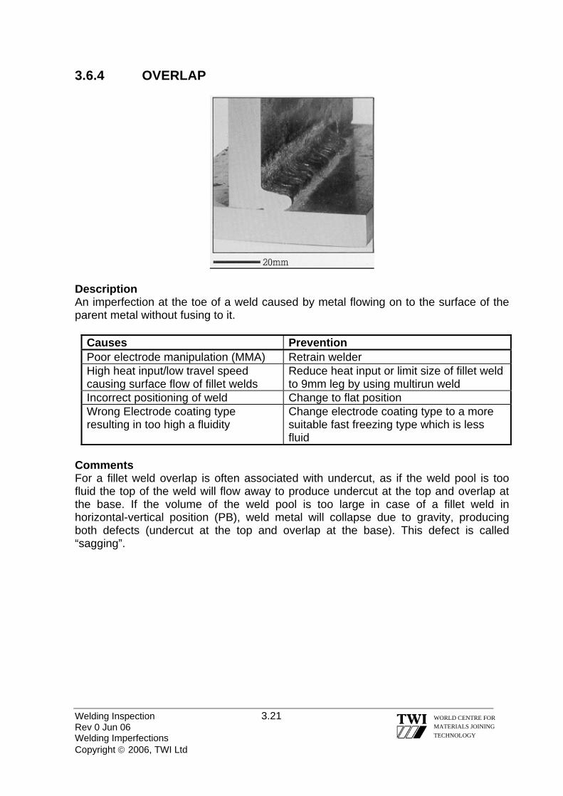
Description An imperfection at the toe of a weld caused by metal flowing on to the surface of the parent metal without fusing to it.
Causes Prevention Poor electrode manipulation (MMA) Retrain welder High heat input/low travel speed causing surface flow of fillet welds
Reduce heat input or limit size of fillet weld to 9mm leg by using multirun weld
Incorrect positioning of weld Change to flat position Wrong Electrode coating type resulting in too high a fluidity
Change electrode coating type to a more suitable fast freezing type which is less fluid
Comments For a fillet weld overlap is often associated with undercut, as if the weld pool is too fluid the top of the weld will flow away to produce undercut at the top and overlap at the base. If the volume of the weld pool is too large in case of a fillet weld in horizontal-vertical position (PB), weld metal will collapse due to gravity, producing both defects (undercut at the top and overlap at the base). This defect is called “sagging”.
Welding Inspection 3.21 Rev 0 Jun 06 Welding Imperfections Copyright © 2006, TWI Ltd
WORLD CENTRE FOR MATERIALS JOINING TECHNOLOGY

3.6.5 LINEAR MISALIGNMENT
Description Misalignment between two welded pieces such that while their surface planes are parallel, they are not in the required same plane.
Causes Prevention Inaccuracies in assembly procedures or distortion from other welds
Adequate checking of alignment prior to welding coupled with the use of clamps and wedges
Excessive ‘out of flatness’ in hot rolled plates or sections
Check accuracy of rolled section prior to welding
Comments Misalignment is not really a weld imperfection, but a structural preparation problem. Even a small amount of misalignment can drastically increase the local shear stress at a joint and induce bending stress.
3.6.6 ANGULAR MISALIGNMENT
Welding Inspection 3.22 Rev 0 Jun 06 Welding Imperfections Copyright © 2006, TWI Ltd
WORLD CENTRE FOR MATERIALS JOINING TECHNOLOGY

Description Misalignment between two welded pieces such that their surface planes are not parallel or at the intended angle. Causes and prevention Same as for linear misalignment.
3.6.7 INCOMPLETELY FILLED GROOVE
Description A continuos or intermittent channel in the surface of a weld due to insufficient deposition of weld filler metal.
Causes Prevention Insufficient weld metal Increase the number of weld runs Irregular weld bead surface Retrain welder
Comments This imperfection differs from undercut, as incompletely filled groove reduces the load bearing capacity of a weld, whereas undercut produces a sharp stress-raising notch at the edge of a weld.
Welding Inspection 3.23 Rev 0 Jun 06 Welding Imperfections Copyright © 2006, TWI Ltd
WORLD CENTRE FOR MATERIALS JOINING TECHNOLOGY

3.6.8 IRREGULAR WIDTH Description Excessive variation in width of the weld. Causes Prevention Severe arc blow Switch from DC to AC, keep an as short as
possible arc length Irregular weld bead surface Retrain welder Comments Although this imperfection may not affect the integrity of completed weld, it can affect the width of HAZ and reduce the load carrying capacity of the joint (in case of fine-grained structural steels) or impair corrosion resistance (in case of duplex stainless steels). 3.6.9 ROOT CONCAVITY
Description A shallow groove that occurs due to shrinkage at the root of a butt weld.
Welding Inspection 3.24 Rev 0 Jun 06 Welding Imperfections Copyright © 2006, TWI Ltd
WORLD CENTRE FOR MATERIALS JOINING TECHNOLOGY

Causes Prevention Insufficient arc power to produce positive bead
Raise arc energy
Excessive backing gas pressure (TIG) Reduce gas pressure Lack of welder skill Retrain welder Slag flooding in backing bar groove Tilt work to prevent slag flooding
Comments The use of a backing strip can be used to control the extent of the root bead. 3.6.10 BURN THROUGH
Description A collapse of the weld pool resulting in a hole in the weld.
Causes Prevention Insufficient travel speed Increase the travel speed Excessive welding current Reduce welding current Lack of welder skill Retrain welder Excessive grinding of root face More care taken, retrain welder Excessive root gap Ensure correct fit up
Comments This is a gross imperfection, which occurs basically due to lack of welder skill. It can be repaired by bridging the gap formed into the joint, but requires a great deal of attention.
Welding Inspection 3.25 Rev 0 Jun 06 Welding Imperfections Copyright © 2006, TWI Ltd
WORLD CENTRE FOR MATERIALS JOINING TECHNOLOGY

3.7 MISCELLANEOUS IMPERFECTIONS
3.7.1 STRAY ARC
Description Local damage to the surface of the parent metal adjacent to the weld, resulting from arcing or striking the arc outside the weld groove. The result is in form of random areas of fused metal where the electrode, the holder, or current return clamp have accidentally touched the work.
Causes Prevention Poor access to the work Improve access (modify assembly
sequence) Missing insulation on electrode holder or torch
Institute a regular inspection scheme for electrode holders and torches
Failure to provide an insulated resting place for the electrode holder or torch when not in use
Provide an insulated resting place
Loose current return clamp Regularly maintain current return clamps Adjusting wire feed (MAG welding) without isolating welding current
Retrain welder
Comments An arc strike can produce a hard heat-affected zone, which may contain cracks. These can lead to serious cracking in service. It is better to remove an arc strike by grinding than weld repair.
Welding Inspection 3.26 Rev 0 Jun 06 Welding Imperfections Copyright © 2006, TWI Ltd
WORLD CENTRE FOR MATERIALS JOINING TECHNOLOGY
3.7.2 SPATTER
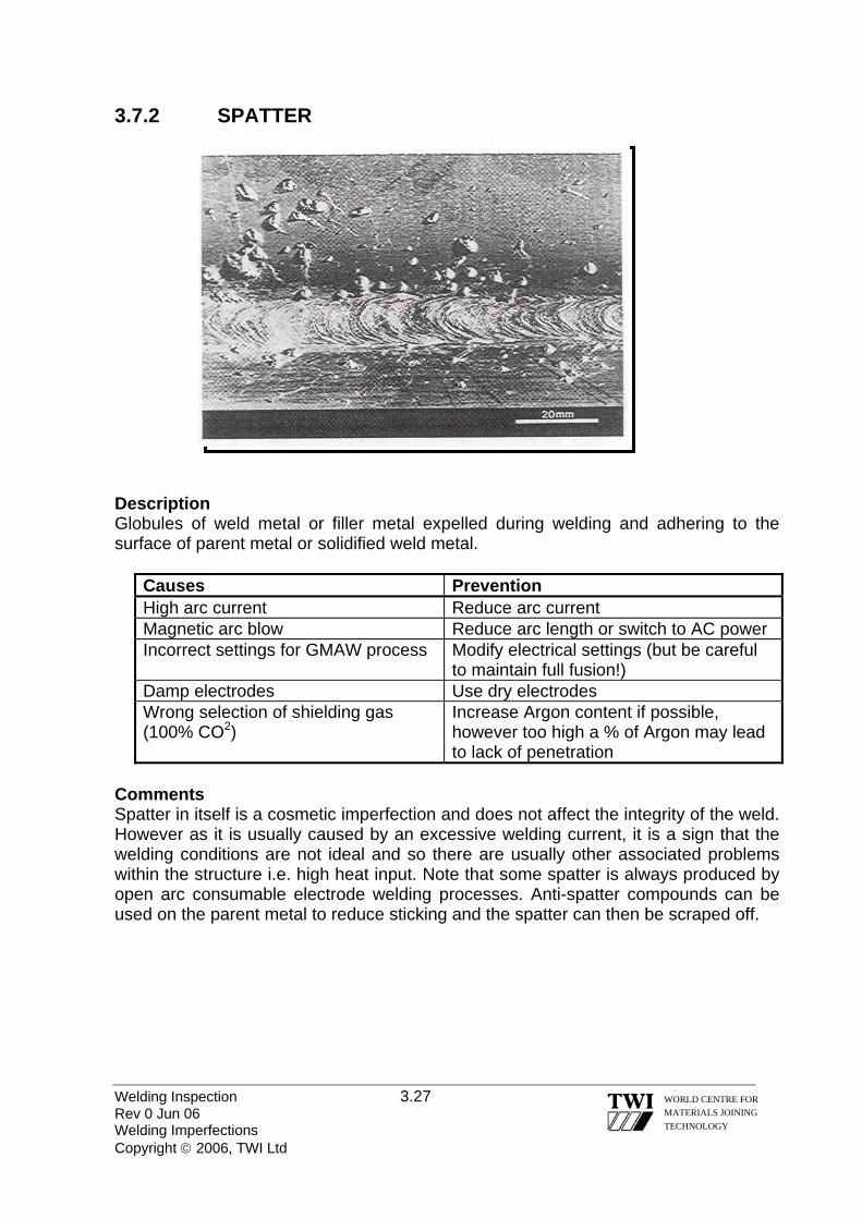
Description Globules of weld metal or filler metal expelled during welding and adhering to the surface of parent metal or solidified weld metal.
Causes Prevention High arc current Reduce arc current Magnetic arc blow Reduce arc length or switch to AC power Incorrect settings for GMAW process Modify electrical settings (but be careful
to maintain full fusion!) Damp electrodes Use dry electrodes Wrong selection of shielding gas (100% CO2)
Increase Argon content if possible, however too high a % of Argon may lead to lack of penetration
Comments Spatter in itself is a cosmetic imperfection and does not affect the integrity of the weld. However as it is usually caused by an excessive welding current, it is a sign that the welding conditions are not ideal and so there are usually other associated problems within the structure i.e. high heat input. Note that some spatter is always produced by open arc consumable electrode welding processes. Anti-spatter compounds can be used on the parent metal to reduce sticking and the spatter can then be scraped off.
Welding Inspection 3.27 Rev 0 Jun 06 Welding Imperfections Copyright © 2006, TWI Ltd
WORLD CENTRE FOR MATERIALS JOINING TECHNOLOGY

Welding Inspection 3.28 Rev 0 Jun 06 Welding Imperfections Copyright © 2006, TWI Ltd
WORLD CENTRE FOR MATERIALS JOINING TECHNOLOGY
3.7.3 TORN SURFACE
Description Surface damage due to the removal by fracture of temporary welded attachments. The area should be grinded off, then subjected to a dye penetrant or magnetic particle examination and then restored to its original shape by welding using a qualified procedure. NOTE: Some applications do not allow the presence of any overlay weld on the surface of the parent material. 3.7.4 ADDITIONAL IMPERFECTIONS Grinding mark
Description Local damage due to grinding. Chipping mark
Description Local damage due to the use of a chisel or other tools. Underflushing
Description Lack of thickness of the workpiece due to excessive grinding. Misalignment of opposite runs
Description Difference between the centrelines of two runs made from opposite sides of the joint.

Temper colour (visible oxide film)
Description Lightly oxidised surface in the weld zone. Usually occurs in case of stainless steels.
3.8 ACCEPTANCE STANDARDS
Weld imperfections can seriously reduce the integrity of a welded structure. Therefore, prior to service of a welded joint, it is necessary to locate them using NDE techniques, assess their significance, and take action to avoid their reoccurrence.
The acceptance of a certain size and type of defect for a given structure is normally expressed as the defect acceptance standard. This is usually incorporated in application standards or specifications. All normal weld imperfection acceptance standards totally reject cracks. However, in exceptional circumstances, and subject to the agreement of all parties, cracks may be allowed to remain if it can be demonstrated beyond doubt that they will not lead to failure. This can be difficult to establish and usually involves fracture mechanics measurements and calculations.
It is important to note that the levels of acceptability vary between different applications, and in most cases vary between different standards for the same application. Consequently, when inspecting different jobs it is important to use the applicable standard or specification quoted in the contract.
Once unacceptable weld imperfections have been found, they have to be removed. If the weld imperfection is at the surface, the first consideration is whether it is of a type, which is normally shallow enough to be repaired by superficial dressing. Superficial implies that, after removal of the defect, the remaining material thickness is sufficient not to require the addition of further weld metal.
Welding Inspection 3.29
If the defect is too deep, it must be removed by some means and new weld metal added to ensure a minimum design throat thickness.
Rev 0 Jun 06 Welding Imperfections Copyright © 2006, TWI Ltd
WORLD CENTRE FOR MATERIALS JOINING TECHNOLOGY
Welding Inspection 3.30 Rev 0 Jun 06 Welding Imperfections Copyright © 2006, TWI Ltd
WORLD CENTRE FOR MATERIALS JOINING TECHNOLOGY
Replacing removed metal or weld repair (as in filling an excavation or re-
making a weld joint) has to be done in accordance with an approved procedure. The rigor with which this procedure is qualified will depend on the application standard for the job. In some cases it will be acceptable to use a procedure qualified for making new joints whether filling an excavation or making a complete joint. If the level of reassurance required is higher, the qualification will have to be made using an exact simulation of a welded joint, which is excavated and then refilled using a specified method. In either case, qualification inspection and testing will be required in accordance with the application standard.

Welding Inspection Rev 0 Jun 06 Copyright © 2006, TWI Ltd
WORLD CENTRE FOR MATERIALS JOINING TECHNOLOGY
Section 04
Destructive Testing

Welding Inspection 4.1 Rev 0 Jun 06 Destructive Testing Copyright © 2006, TWI Ltd
WORLD CENTRE FOR MATERIALS JOINING TECHNOLOGY
4.0 DESTRUCTIVE TESTING 4.1 INTRODUCTION
European Welding Standards require test coupons that are made for welding procedure qualification testing to be subjected to non-destructive testing and then destructive testing.
The tests are called destructive tests because the welded joint is ‘destroyed’ when various types of test piece are taken from it. Destructive tests can be divided into 2 groups, namely: -
those used to measure a mechanical property – quantitative tests those used to assess the joint quality – qualitative tests
Mechanical tests are quantitative because a quantity is measured – a
mechanical property such as tensile strength, hardness and impact toughness.
Qualitative tests are used to verify that the joint is free from defects – they are of sound quality - and examples of these are bend tests, macroscopic examination and fracture tests (fillet fracture & nick-break). 4.2 TEST TYPES, TEST PIECES & TEST OBJECTIVES
The various types of mechanical test are used by material manufacturers/ suppliers to verify that plates, pipes, forgings etc have the minimum property values specified for particular grades.
Design engineers use the minimum property values listed for particular grades of material as the basis for design and the most cost effective designs are based on an assumption that welded joints have properties that are no worse than those of the base metal.
The quantitative (mechanical) tests that are carried out for welding procedure qualification are intended to demonstrate that the joint properties satisfy design requirements.
The emphasis in the following sub-sections is the destructive tests and test methods that are widely used for welded joints.

4.2.1 TRANSVERSE TENSILE TESTS • Test Objective Welding procedure qualification tests always require transverse tensile tests to show that the strength of the joint satisfies the design criterion. • Test Specimens A transverse tensile test piece typical of the type specified by European Welding Standards is shown below. parallel
length
Standards, such as EN 895, that specify dimensions for transverse tensile test pieces require all excess weld metal to be removed and the surface to be free from scratches.
Test pieces may be machined to represent the full thickness of the joint but for very thick joints it may be necessary to take several transverse tensile test specimens to be able to test the full thickness. • Test Method
Test specimens are accurately measured before testing. Specimens are then fitted into the jaws of a tensile testing machine and subjected to a continually increasing tensile force until the specimen fractures.
The tensile strength is calculated by dividing the maximum load by the cross-sectional area of the test specimen - measured before testing.
The test is intended to measure the tensile strength of the joint and thereby show that the basis for design, the base metal properties, remains the valid criterion. • Acceptance Criteria
If the test piece breaks in the weld metal, it is acceptable provided the calculated strength is not less than the minimum tensile strength specified, which is usually the minimum specified for the base metal material grade.
Welding Inspection 4.2 Rev 0 Jun 06 Destructive Testing Copyright © 2006, TWI Ltd
WORLD CENTRE FOR MATERIALS JOINING TECHNOLOGY
If the test specimen breaks outside the weld or fusion zone, the weld joint strength may be acceptable provided that it is not less than 95% of the minimum tensile strength specified for the base metal. 4.2.2 ALL-WELD TENSILE TESTS • Test Objective There may be occasions when it is necessary to measure the weld metal strength as part of welding procedure qualification – particularly for elevated temperature designs.
The test is carried out in order to measure not only tensile strength but also yield (or proof strength) and tensile ductility.
All-weld tensile tests are also regularly carry out by welding consumable manufacturers to verify that electrodes and filler wires satisfy the tensile properties specified by the standard to which the consumables are certified. • Test Specimens
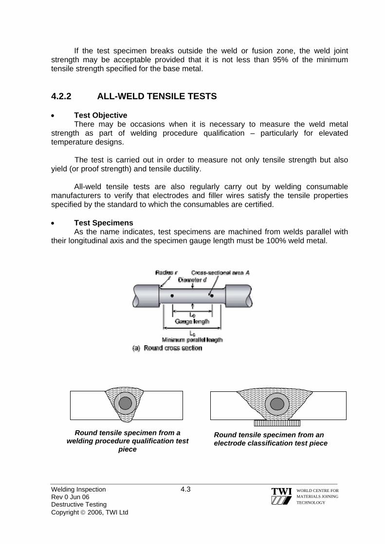
As the name indicates, test specimens are machined from welds parallel with their longitudinal axis and the specimen gauge length must be 100% weld metal.
Round tensile specimen from a welding procedure qualification test
piece
Round tensile specimen from an electrode classification test piece
Welding Inspection 4.3 Rev 0 Jun 06 Destructive Testing Copyright © 2006, TWI Ltd
WORLD CENTRE FOR MATERIALS JOINING TECHNOLOGY
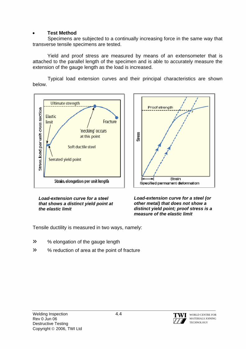
• Test Method Specimens are subjected to a continually increasing force in the same way that transverse tensile specimens are tested. Yield and proof stress are measured by means of an extensometer that is attached to the parallel length of the specimen and is able to accurately measure the extension of the gauge length as the load is increased.
Typical load extension curves and their principal characteristics are shown below.
Load-extension curve for a steel (or other metal) that does not show a distinct yield point; proof stress is a measure of the elastic limit
Load-extension curve for a steel that shows a distinct yield point at the elastic limit
Tensile ductility is measured in two ways, namely:
» % elongation of the gauge length
» % reduction of area at the point of fracture
Welding Inspection 4.4 Rev 0 Jun 06 Destructive Testing Copyright © 2006, TWI Ltd
WORLD CENTRE FOR MATERIALS JOINING TECHNOLOGY

Schematics (a) and (b) below illustrate these two ductility measurements. 4.2.3 IMPACT TOUGHNESS TESTS • Test Objective Charpy V-notch test pieces have become the internationally accepted method for assessing resistance to brittle fracture by measuring the energy to initiate, and propagate, a crack from a sharp notch in a standard sized specimen subjected to an impact load.
Design engineers need to ensure that the toughness of the steel that is used for a particular item will be high enough to avoid brittle fracture in service and so impact specimens are tested at a temperature that is related to the design temperature for the fabricated component.
C-Mn and low alloy steels undergo a sharp change in their resistance to brittle fracture as their temperature is lowered so that a steel that may have very good toughness at ambient temperature may show extreme brittleness at sub-zero temperatures – as illustrated in following figure.
Welding Inspection 4.5 Rev 0 Jun 06 Destructive Testing Copyright © 2006, TWI Ltd
WORLD CENTRE FOR MATERIALS JOINING TECHNOLOGY

Welding Inspection 4.6 Rev 0 Jun 06 Destructive Testing Copyright © 2006, TWI Ltd
WORLD CENTRE FOR MATERIALS JOINING TECHNOLOGY
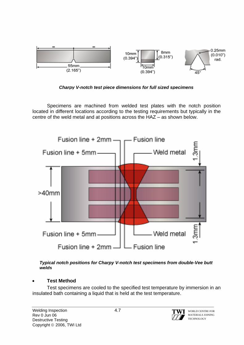
The transition temperature is defined as the temperature that is mid-way between the upper shelf (maximum toughness) and lower shelf (completely brittle). In the above schematic the transition temperature is –20°C. • Test Specimens The dimensions for test specimens have been standardised internationally and are shown below for full sized specimens. There are also standard dimensions for smaller sized specimens, for example 10mm x 7.5mm & 10mm x 5mm.
-50 -40 -30 -20 -10 0 10 20 30 40
Test Temperature (°C)
Impa
ct E
nerg
y (J
oule
s)
upper shelf energy
lower shelf energy
Transition Temperature (-20°C)
ductile fracture (0% crystallinity)
brittle fracture (100% crystallinity)
Welding Inspection 4.7 Rev 0 Jun 06 Destructive Testing Copyright © 2006, TWI Ltd
WORLD CENTRE FOR MATERIALS JOINING TECHNOLOGY
Charpy V-notch test piece dimensions for full sized specimens
Specimens are machined from welded test plates with the notch position located in different locations according to the testing requirements but typically in the centre of the weld metal and at positions across the HAZ – as shown below.
Typical notch positions for Charpy V-notch test specimens from double-Vee butt welds
• Test Method Test specimens are cooled to the specified test temperature by immersion in an insulated bath containing a liquid that is held at the test temperature.

After allowing the specimen temperature to stabilise for a few minutes it is quickly transferred to the ‘anvil’ of the test machine and a pendulum hammer quickly released so that the specimen experiences an impact load behind the notch. The main features of an impact test machine are shown below.
Impact specimen on the anvil showing the hammer position at point of impact
Impact testing machine
Charpy V-notch test pieces – before and after testing
Welding Inspection 4.8 Rev 0 Jun 06 Destructive Testing Copyright © 2006, TWI Ltd
WORLD CENTRE FOR MATERIALS JOINING TECHNOLOGY

The energy ‘absorbed’ by the hammer when it strikes each test specimen is shown by the position of the hammer ‘pointer’ on the scale of the machine. Energy values are given in Joules. Impact test specimens are taken in triplicate (3 specimens for each notch position) because there is will always tend to be some variation in recorded energy for nominally the same test – particularly for weldments. • Acceptance Criteria Each test result is recorded and an average value calculated for each set of three tests. These values are compared with the values specified by the Application Standard or Client to establish whether specified requirements have been met. After impact testing, examination of the test specimens provides additional information about their toughness characteristics and may be added to the test report, namely: -
» % crystallinity – the % of the fracture face that has ‘crystalline’ appearance which indicates brittle fracture; 100% indicates completely brittle fracture
» lateral expansion – the increase in width of the back of the specimen behind the notch – as indicated below; the larger the value the tougher the specimen
A specimen that exhibits extreme brittleness will show a clean break with and both halves of the specimen having a completely flat fracture faces with little or no lateral expansion.
Welding Inspection 4.9 Rev 0 Jun 06 Destructive Testing Copyright © 2006, TWI Ltd
WORLD CENTRE FOR MATERIALS JOINING TECHNOLOGY
Welding Inspection 4.10 Rev 0 Jun 06 Destructive Testing Copyright © 2006, TWI Ltd
WORLD CENTRE FOR MATERIALS JOINING TECHNOLOGY
A specimen that exhibits very good toughness will show only a small degree of crack extension, without fracture and a high value of lateral expansion. 4.2.4 HARDNESS TESTING • Test Objective The hardness of a metal is its’ resistance to plastic deformation and this is determined by measuring the resistance to indentation by a particular type of indenter. A steel weldment with hardness above a certain maximum may be susceptible to cracking, either during fabrication or in service, and welding procedure qualification testing for certain steels and certain applications requires the test weld to be hardness surveyed to ensure that are no regions of the weldment that exceed the maximum specified hardness. Specimens prepared for macroscopic examination can also be used for taking hardness measurements at various positions of the weldment – referred to as a hardness survey. • Test Methods There are 3 widely used methods for hardness testing, namely:
• The Vickers hardness test – uses a square-base diamond pyramid indenter
• The Rockwell hardness test – uses a diamond cone indenter or steel ball • The Brinell hardness test – uses a ball indenter
The size of an indentation is the measure used to give a hardness value - the smaller the indentation the harder the metal.

The Vickers method of testing is illustrated by the schematic shown below.
2ddd 21+=
Both Vickers and Brinell methods are suitable for carrying out hardness surveys on specimens prepared for macroscopic examination of weldments. A typical hardness survey requires the indenter to measure the hardness in the base metal (on both sides of the weld), in the weld metal and across the HAZ (on both sides of the weld). The Brinell method gives an indentation that is too large to accurately measure the hardness in specific regions of the HAZ and is mainly used to measure hardness of base metals.
Welding Inspection 4.11 Rev 0 Jun 06 Destructive Testing Copyright © 2006, TWI Ltd
WORLD CENTRE FOR MATERIALS JOINING TECHNOLOGY

A typical hardness survey (using Vickers hardness indenter) is shown below: Hardness values are shown on test reports as a number followed by letters indicating the test method, for example: 240 HV10 = hardness 240, Vickers method, 10 Kg indenter load
22 HRC = hardness 22, Rockwell method, diamond cone indenter (scale C)
238 HBW = 238 hardness, Brinell method, tungsten ball indenter
4.2.5 CRACK TIP OPENING DISPLACEMENT (CTOD) TESTING • Test Objective Charpy V-notch testing enables engineers to make judgements about risks of brittle fracture occurring in steels but a CTOD test measures a material property - fracture toughness. Fracture toughness data enables engineers to carry out fracture mechanics analyses such as: -
• calculating the size of a crack that would initiate a brittle fracture under certain stress conditions at a particular temperature
• the stress that would cause a certain sized crack to give a brittle fracture
at a particular temperature This data is essential for making an appropriate decision when a crack is discovered during inspection of equipment that is in-service. • Test Specimens A CTOD specimen is prepared as a rectangular (or square) shaped bar cut transverse to the axis of the butt weld. A V-notch is machined at the centre of the bar, which will be coincident with the test position - weld metal or HAZ.
Welding Inspection 4.12 Rev 0 Jun 06 Destructive Testing Copyright © 2006, TWI Ltd
WORLD CENTRE FOR MATERIALS JOINING TECHNOLOGY

A shallow saw cut is then put into the bottom of the notch and the specimen is then put into a machine that induces a cyclic bending load until a shallow fatigue crack initiates from the saw cut.
The specimens are relatively large – typically having a cross section B x 2B and length ~10B (B = full thickness of the weld). The test piece details are shown in the schematic below.
• Test Method CTOD specimens are usually tested at a temperature below ambient and the temperature of the specimen is controlled by immersion in a bath of liquid that has been cooled to the required test temperature. A load is applied to the specimen to bend cause bending and induce a concentrated stress at the tip of the crack and a clip gauge, attached to the specimen across the mouth of the machined notch, gives a reading of the increase in width of the mouth of the crack as the load is gradually increased. For each ‘test condition’ (position of notch and test temperature) it is usual practice to carry out three tests.
Welding Inspection 4.13 Rev 0 Jun 06 Destructive Testing Copyright © 2006, TWI Ltd
WORLD CENTRE FOR MATERIALS JOINING TECHNOLOGY

The schematics below illustrate the main features of the CTOD test. Fracture toughness is expressed as the distance that the crack tip opens without initiation of a brittle crack. The clip gauge enables a chart to be generated showing the increase in width of the crack mouth against applied load from which a CTOD value is calculated. • Acceptance Criteria An application standard or Client may specify a minimum CTOD value that indicates ductile tearing. Alternatively, the test may be ‘for information’ so that a value can be used for an engineering critical assessment. A very tough steel weldment will allow the mouth of the crack to open widely by ductile tearing at the tip of the crack whereas a very brittle weldment will tend to fracture when the applied load is quite low and without any extension at the tip of the crack.
Welding Inspection 4.14
CTOD values are expressed in millimetres - typical values might be << ~ 0.1mm = brittle behaviour; > ~1mm = very tough behaviour.
Rev 0 Jun 06 Destructive Testing Copyright © 2006, TWI Ltd
WORLD CENTRE FOR MATERIALS JOINING TECHNOLOGY

4.2.6 BEND TESTING • Test Objective Bend tests are routinely taken from welding procedure qualification test pieces and sometimes have to be taken from welder qualification test pieces. Subjecting specimens to bending is a simple method of verifying that there are no regions in a butt weld that have low ductility. Ductility is not actually measured but it is demonstrated to be satisfactory if test specimens can withstand being bent without fracture or fissures above a certain length. • Test Specimens
There are 4 types of bend specimen, namely:
Face bend Specimen taken with axis transverse to butt welds up to ~12mm thickness and bent so that the face of the weld is on the outside of the bend (face in tension) Root bend Test specimen taken with axis transverse to butt welds up to ~12mm thickness and bent so that the root of the weld is on the outside of the bend (root in tension) Side bend Test specimen taken as a transverse slice (~10mm) from the full thickness of butt welds > ~12mm and bent so that the full joint thickness tested (side in tension) Longitudinal Bend Test specimen taken with axis parallel to the longitudinal axis of a butt weld; specimen thickness is ~ 12mm and the face or root of weld may be tested in tension
Welding Inspection 4.15 Rev 0 Jun 06 Destructive Testing Copyright © 2006, TWI Ltd
WORLD CENTRE FOR MATERIALS JOINING TECHNOLOGY
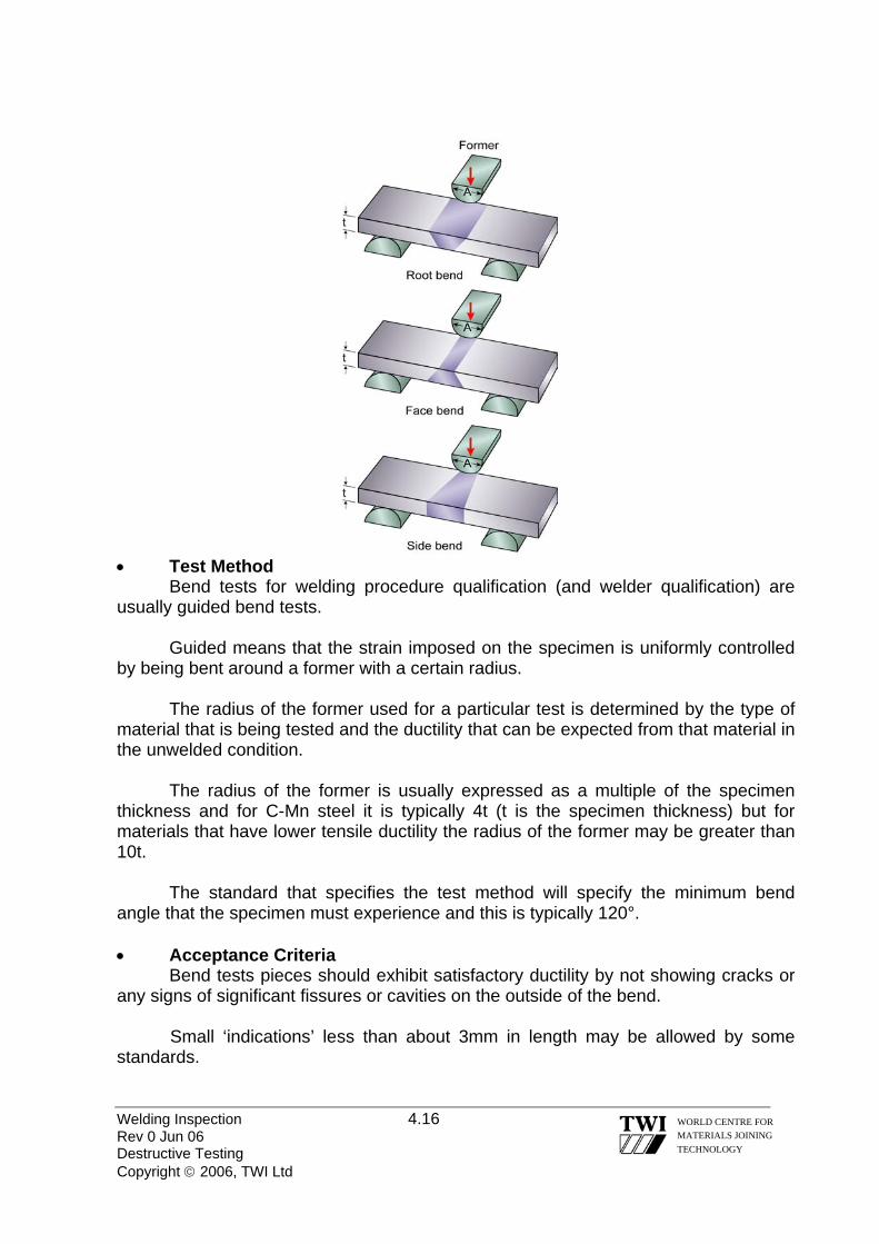
Welding Inspection 4.16 Rev 0 Jun 06 Destructive Testing Copyright © 2006, TWI Ltd
WORLD CENTRE FOR MATERIALS JOINING TECHNOLOGY
• Test Method
Bend tests for welding procedure qualification (and welder qualification) are usually guided bend tests. Guided means that the strain imposed on the specimen is uniformly controlled by being bent around a former with a certain radius. The radius of the former used for a particular test is determined by the type of material that is being tested and the ductility that can be expected from that material in the unwelded condition. The radius of the former is usually expressed as a multiple of the specimen thickness and for C-Mn steel it is typically 4t (t is the specimen thickness) but for materials that have lower tensile ductility the radius of the former may be greater than 10t. The standard that specifies the test method will specify the minimum bend angle that the specimen must experience and this is typically 120°. • Acceptance Criteria Bend tests pieces should exhibit satisfactory ductility by not showing cracks or any signs of significant fissures or cavities on the outside of the bend.
Small ‘indications’ less than about 3mm in length may be allowed by some standards.
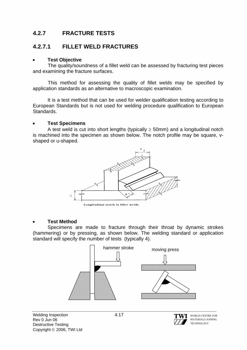
4.2.7 FRACTURE TESTS 4.2.7.1 FILLET WELD FRACTURES • Test Objective The quality/soundness of a fillet weld can be assessed by fracturing test pieces and examining the fracture surfaces.
This method for assessing the quality of fillet welds may be specified by application standards as an alternative to macroscopic examination.
It is a test method that can be used for welder qualification testing according to European Standards but is not used for welding procedure qualification to European Standards. • Test Specimens A test weld is cut into short lengths (typically ≥ 50mm) and a longitudinal notch is machined into the specimen as shown below. The notch profile may be square, v-shaped or u-shaped. • Test Method Specimens are made to fracture through their throat by dynamic strokes (hammering) or by pressing, as shown below. The welding standard or application standard will specify the number of tests (typically 4).
hammer stroke moving press Welding Inspection 4.17 Rev 0 Jun 06 Destructive Testing Copyright © 2006, TWI Ltd
WORLD CENTRE FOR MATERIALS JOINING TECHNOLOGY

• Acceptance Criteria The standard for welder qualification, or application standard, will specify the acceptance criteria for imperfections such as lack of penetration into the root of the joint and solid inclusions and porosity that are visible on the fracture surfaces. Test reports should also give a description of the appearance of the fracture and location of any imperfection 4.2.7.2 BUTT WELD FRACTURES (‘NICK-BREAK’ TESTS) • Test Objective
The objective of these fracture tests is the same as for fillet fracture tests.
These tests are specified for welder qualification testing to European Standards as an alternative to radiography, or are additional to radiography for certain welding processes, but it is not used for welding procedure qualification testing to European Standards. • Test Specimens Test specimens are taken from a butt weld and notched so that the fracture path will be in the central region of the weld. Typical test piece types are shown below. • Test Method Test pieces are made to fracture by hammering or three-point bending. • Acceptance Criteria The standard for welder qualification, or application standard, will specify the acceptance criteria for imperfections such as lack of fusion, solid inclusions and porosity that are visible on the fracture surfaces. Test reports should also give a description of the appearance of the fracture and location of any imperfection. Welding Inspection 4.18 Rev 0 Jun 06 Destructive Testing Copyright © 2006, TWI Ltd
WORLD CENTRE FOR MATERIALS JOINING TECHNOLOGY

Welding Inspection 4.19 Rev 0 Jun 06 Destructive Testing Copyright © 2006, TWI Ltd
WORLD CENTRE FOR MATERIALS JOINING TECHNOLOGY
4.3 MACROSCOPIC EXAMINATION Transverse sections from butt and fillet welds are required by the European Standards for welding procedure qualification testing and may be required for some welder qualification testing for assessing the quality of the welds.
This is considered in detail in a separate Section of these Course Notes. 4.4 EUROPEAN STANDARDS FOR DESTRUCTIVE TEST METHODS The following Standards are specified by the European Welding Standards for destructive testing of welding procedure qualification test welds and for some welder qualification test welds. EN 875 Destructive tests on welds in metallic materials – Impact tests – Test
specimen location, notch orientation and examination EN 895 Destructive tests on welds in metallic materials – Transverse tensile
test EN 910 Destructive tests on welds in metallic materials – Bend tests EN 1321 Destructive tests on welds in metallic materials – Macroscopic and
microscopic examination of welds BS EN 10002 Metallic materials - Tensile testing. Part 1: Method of test at ambient
temperature BS EN 10002 Tensile testing of metallic materials. Part 5: Method of test at elevated
temperatures

Welding Inspection Rev 0 Jun 06 Copyright © 2006, TWI Ltd
WORLD CENTRE FOR MATERIALS JOINING TECHNOLOGY
Section 05
WPS & Welder Qualifications

Welding Inspection 5.1 Rev 0 Jun 06 WPS and Welder Qualifications Copyright © 2006, TWI Ltd
WORLD CENTRE FOR MATERIALS JOINING TECHNOLOGY
5.0 WELDING PROCEDURE QUALIFICATION & WELDER QUALIFICATION
GENERAL
When structures and pressurised items are fabricated by welding, it is essential that all the welded joints are sound and have suitable properties for their application.
Control of welding is achieved by means of Welding Procedure Specifications (WPS’s) that give detailed written instructions about the welding conditions that must be used to ensure that welded joints have the required properties.
Although WPS’s are ‘shop floor’ documents to instruct welders, they are documents that welding inspectors also need to be familiar with. This is because they will need to refer to WPS’s when they are checking that welders are working in accordance with the specified requirements.
Welders need to be able to understand WPS’s and to have the skill to make welds that are not defective and have to demonstrate these abilities before being allowed to make production welds. 5.1 QUALIFIED WELDING PROCEDURE SPECIFICATIONS
It is industry practice to use qualified WPS’s for most applications.
A welding procedure is usually qualified by making a test weld to demonstrate that the properties of the joint satisfy the requirements specified by the application standard (and the Client/End User).
Demonstrating the mechanical properties of the joint is the principle purpose of qualification tests but showing that a defect-free weld can be produced is also very important.
Production welds that are made in accordance with welding conditions similar to those used for a test weld should have similar properties and therefore be ‘fit for their intended purpose’.
Figure 1 is an example of a typical WPS written in accordance with the European Welding Standard format giving details of all the welding conditions that need to be specified. 5.1.1 WELDING STANDARDS FOR PROCEDURE
QUALIFICATION
European and American Standards have been developed to give comprehensive details about:
Welding Inspection 5.2 Rev 0 Jun 06 WPS and Welder Qualifications Copyright © 2006, TWI Ltd
WORLD CENTRE FOR MATERIALS JOINING TECHNOLOGY
how a welded test piece must be made to demonstrate joint properties how the test piece must be tested what welding details need to be included in a WPS the range of production welding allowed by a particular qualification test weld
The principal European Standards that specify these requirements are: EN ISO 15614 Specification & qualification of welding procedures for metallic
materials – Welding procedure test Part 1: Arc & gas welding of steels & arc welding of nickel &
nickel alloys Part 2: Arc welding of aluminium and its alloys
The principal American Standards for procedure qualification are: ASME Section IX for pressurised systems (vessels & pipework) AWS D1.1 for structural welding of steels AWS D1.2 for structural welding of aluminium 5.1.2 THE QUALIFICATION PROCESS FOR WELDING PROCEDURES
Although qualified WPS’s are usually based on test welds that have been made to demonstrate weld joint properties; welding standards also allow qualified WPS’s to be written based on other data (for some applications).
Some alternative ways that can be used for writing qualified WPS’s for some applications are:
qualification by adoption of a standard welding procedure - test welds previously qualified and documented by other manufacturers
qualification based on previous welding experience - weld joints that have
been repeatedly made and proved to have suitable properties by their service record
Procedure qualification to European Standards by means of a test weld (and
similar in ASME Section IX and AWS) requires a sequence of actions that is typified by those shown by Table 1.
A successful procedure qualification test is completed by the production of a Welding Procedure Qualification Record (WPQR), an example of which is shown by Figure 2.

Welding Inspection 5.3 Rev 0 Jun 06 WPS and Welder Qualifications Copyright © 2006, TWI Ltd
WORLD CENTRE FOR MATERIALS JOINING TECHNOLOGY
5.1.3 RELATIONSHIP BETWEEN A WPQR & A WPS
Once a WPQR has been produced, the welding engineer is able to write qualified WPS’s for the various production weld joints that need to be made.
The welding conditions that are allowed to be written on a qualified WPS are referred to as the qualification range and this range depends on the welding conditions that were used for the test piece (the as-run details) and form part of the WPQR.
Welding conditions are referred to as welding variables by European & American Welding Standards and are classified as either essential variables or non-essential variables. These variables can be defined as follows: • essential variable a variable that has an affect on the mechanical properties
of the weldment (and if changed beyond the limits specified by the standard will
require the WPS to be re-qualified) • non-essential variable a variable that must be specified on a WPS but does
not have a significant effect on the mechanical properties of the weldment (and can be changed without need for re-qualification but will require a new WPS to be written)
It is because essential variables can have a significant effect on mechanical
properties that they are the controlling variables that govern the qualification range and determine what can be written into a WPS.
If a welder makes a production weld using conditions outside the qualification range given on a particular WPS, there is danger that the welded joint will not have the required properties and there are then two options: - 1 Make another test weld using similar welding conditions to those used for the
affected weld and subject this to the same tests used for the relevant WPQR to demonstrate that the properties still satisfy specified requirements
2 Remove the affected weld and re-weld the joint strictly in accordance with the
designated WPS
Most of the welding variables that are classed as ‘essential’ are the same in both the European and American Welding Standards but their qualification ranges may differ.
Some Application Standards specify their own essential variables and it is necessary to ensure that these are taken into consideration when procedures are qualified and WPS’s are written.

Welding Inspection 5.4 Rev 0 Jun 06 WPS and Welder Qualifications Copyright © 2006, TWI Ltd
WORLD CENTRE FOR MATERIALS JOINING TECHNOLOGY
Examples of essential variables (according to European Welding Standards) are given in Table 2. 5.2 WELDER QUALIFICATION
The use of qualified WPS’s is the accepted method for controlling production welding but this will only be successful if welder have the ability to understand and work in accordance with them.
Welders also need to have the skill to consistently produce sound welds (free from defects).
Welding Standards have been developed to give guidance on what particular test welds are required in order to show that welders have the required skills to make particular types of production welds in particular materials. 5.2.1 WELDING STANDARDS FOR WELDER QUALIFICATION The principal European Standards that specify requirements are: EN 287-1 Qualification test of welders – Fusion welding
Part 1: Steels
EN ISO 9606-2 Qualification test of welders – Fusion welding Part 2: Aluminium and aluminium alloys
EN 1418 Welding personnel – Approval testing of welding operators for
fusion welding and resistance weld setters for fully mechanised and automatic welding of metallic materials
The principal American Standards that specify requirements for welder qualification are: ASME Section IX for pressurised systems (vessels & pipework) AWS D1.1 for structural welding of steels AWS D1.2 for structural welding of aluminium 5.2.2 THE QUALIFICATION PROCESS FOR WELDERS
Qualification testing of welders to European Standards requires test welds to be made and subjected to specified tests to demonstrate that the welder is able to understand the WPS and to produce a sound weld.

Welding Inspection 5.5 Rev 0 Jun 06 WPS and Welder Qualifications Copyright © 2006, TWI Ltd
WORLD CENTRE FOR MATERIALS JOINING TECHNOLOGY
For manual and semi-automatic welding the emphasis of the tests is to demonstrate ability to manipulate the electrode or welding torch.
For mechanised and automatic welding the emphasis is on demonstrating that welding operators have ability to control particular types of welding equipment.
American Standards allow welders to demonstrate that they can produce sound welds by subjecting their first production weld to non-destructive testing. Table 3 shows the steps required for qualifying welders in accordance with European Standards. Figure 3 shows a typical Welder Qualification Certificate in accordance with European Standards. 5.2.3 WELDER QUALIFICATION AND PRODUCTION WELDING ALLOWED
The welder is allowed to make production welds within the range of qualification recorded on his Welder Qualification Certificate.
The range of qualification is based on the limits specified by the Welding Standard for welder qualification essential variabless - defined as:
a variable that if changed beyond the limits specified by the Welding Standard may require greater skill than has been demonstrated by the test weld.
Some welding variables that are classed as essential for welder qualification
are the same types as those classified as essential for welding procedure qualification, but the range of qualification may be significantly wider. Some essential variables are specific to welder qualification. Examples of welder qualification essential variables are given in Table 4. 5.2.4 PERIOD OF VALIDITY FOR A WELDER QUALIFICATION CERTIFICATE A welder’s qualification begins from the date of welding of the test piece. The European Standard allows a qualification certificate to remain valid for a period of two years – provided that:
• the welding co-ordinator, or other responsible person, can confirm that the welder has been working within the initial range of qualification
• working within the initial qualification range is confirmed every six months

Welding Inspection 5.6 Rev 0 Jun 06 WPS and Welder Qualifications Copyright © 2006, TWI Ltd
WORLD CENTRE FOR MATERIALS JOINING TECHNOLOGY
5.2.5 PROLONGATION OF WELDER QUALIFICATION A welder’s qualification certificate can be prolonged every two years by an examiner/examining body but before prolongation is allowed certain conditions need to be satisfied, namely • records/evidence is available that can be traced to the welder and the WPS’s
that have been used for production welding • the ‘supporting evidence’ must relate to volumetric examination of the welder’s
production welds (RT or UT) on two welds made during the 6 months prior to the prolongation date
• the ‘supporting evidence welds’ must satisfy the acceptance levels for
imperfections specified by the European welding standard and have been made under the same conditions as the original test weld.

Welding Inspection 5.7 Rev 0 Jun 06 WPS and Welder Qualifications Copyright © 2006, TWI Ltd
WORLD CENTRE FOR MATERIALS JOINING TECHNOLOGY
TThe welding engineer writes a he welding engineer writes a preliminarypreliminary Welding Procedure Specification (pWPS) for each test coupon to be welded
Welding Procedure Specification(pWPS) for each test coupon to be welded
•• AA wweellddeerr mmaakkeess tthhee tteesstt ccoouuppoonn iinn aaccccoorrddaannccee wwiitthh tthhee ppWWPPSS
•• AA wweellddiinngg iinnssppeeccttoorr rreeccoorrddss aallll tthhee wweellddiinngg ccoonnddiittiioonnss uusseedd ttoo mmaakkee tthhee tteesstt ccoouuppoonn ((ccaalllleedd tthhee ‘‘aass--rruunn’’ ccoonnddiittiioonnss))
AAnn IInnddeeppeennddeenntt EExxaammiinneerr// EExxaammiinniinngg BBooddyy// TThhiirrdd PPaarrttyy IInnssppeeccttoorr mmaayy bbee rreeqquueesstteedd ttoo mmoonniittoorr tthhee pprroocceedduurree qquuaalliiffiiccaattiioonn
TThhee tteesstt ccoouuppoonn iiss ssuubbjjeecctteedd ttoo NNDDTT iinn aaccccoorrddaannccee wwiitthh tthhee mmeetthhooddss ssppeecciiffiieedd bbyy tthhee SSttaannddaarrdd –– vviissuuaall iinnssppeeccttiioonn,, MMTT oorr PPTT && RRTT oorr UUTT
•• TThhee tteesstt ccoouuppoonn iiss ddeessttrruuccttiivveellyy tteesstteedd ((tteennssiillee,, bbeenndd,, mmaaccrroo tteessttss))
•• TThhee CCooddee//AApppplliiccaattiioonn SSttaannddaarrdd//CClliieenntt mmaayy rreeqquuiirree aaddddiittiioonnaall tteessttss ssuucchh aass hhaarrddnneessss tteessttss,, iimmppaacctt tteessttss oorr ccoorrrroossiioonn tteessttss –– ddeeppeennddiinngg oonn mmaatteerriiaall aanndd aapppplliiccaattiioonn
•• AA WWeellddiinngg PPrroocceedduurree QQuuaalliiffiiccaattiioonn RReeccoorrdd ((WWPPQQRR)) iiss pprreeppaarreedd bbyy tthhee wweellddiinngg eennggiinneeeerr ggiivviinngg ddeettaaiillss ooff:: --
»» tthhee aass--rruunn wweellddiinngg ccoonnddiittiioonnss
»» rreessuullttss ooff tthhee NNDDTT
»» rreessuullttss ooff tthhee ddeessttrruuccttiivvee tteessttss
»» tthhee wweellddiinngg ccoonnddiittiioonnss aalllloowweedd ffoorr pprroodduuccttiioonn wweellddiinngg
•• IIff aa TThhiirrdd PPaarrttyy IInnssppeeccttoorr iiss iinnvvoollvveedd hhee wwiillll bbee rreeqquueesstteedd ttoo ssiiggnn tthhee WWPPQQRR aass aa ttrruuee rreeccoorrdd ooff tthhee tteesstt
Table 1 Typical sequence for welding procedure qualification by means of a test weld

VARIABLE RANGE for PROCEDURE QUALIFICATION welding process
no range – process qualified is process that must be used in production
PWHT joints tested after a PWHT and only qualify PWHT production joints joints tested ‘as-welded’ only qualify ‘as-welded’ production joints
parent material type
parent materials of similar composition and mechanical properties are allocated the same Material Group No.; qualification only allows production welding of materials with the same Group No.
welding consumables
consumables for production welding must have the same European designation – as a general rule
material thickness
a thickness range is allowed – below and above the test coupon thickness
type of current AC only qualifies for AC; DC polarity (+VE or -VE) cannot be changed; pulsed current only qualifies for pulsed current production welding the preheat temp. used for the test is the minimum that must be applied
preheat temperature
the highest interpass temperature reached in the test is the max. allowed
interpass temperature
heat input (HI) when impact requirements apply max. HI allowed is 25% above test HI when hardness requirements apply min. HI allowed is 25% below test HI
Table 2 Typical examples of WPS essential variables according to European Welding Standards
Welding Inspection 5.8 Rev 0 Jun 06 WPS and Welder Qualifications Copyright © 2006, TWI Ltd
WORLD CENTRE FOR MATERIALS JOINING TECHNOLOGY

Welding Inspection 5.9 Rev 0 Jun 06 WPS and Welder Qualifications Copyright © 2006, TWI Ltd
WORLD CENTRE FOR MATERIALS JOINING TECHNOLOGY
TThhee wweellddiinngg eennggiinneeeerr wwrriitteess aa WWPPSS ffoorr wweellddeerr qquuaalliiffiiccaattiioonn tteesstt ppiieeccee
•• TThhee wweellddeerr mmaakkeess tthhee tteesstt wweelldd iinn aaccccoorrddaannccee wwiitthh tthhee WWPPSS
•• AA wweellddiinngg iinnssppeeccttoorr mmoonniittoorrss tthhee wweellddiinngg ttoo eennssuurree tthhaatt tthhee wweellddeerr iiss wwoorrkkiinngg iinn aaccccoorrddaannccee tthhee WWPPSS
AAnn IInnddeeppeennddeenntt EExxaammiinneerr// EExxaammiinniinngg BBooddyy// TThhiirrdd PPaarrttyy IInnssppeeccttoorr mmaayy bbee rreeqquueesstteedd ttoo mmoonniittoorr tthhee tteesstt
•• TThhee tteesstt ccoouuppoonn iiss ssuubbjjeecctteedd ttoo NNDDTT iinn aaccccoorrddaannccee wwiitthh tthhee mmeetthhooddss ssppeecciiffiieedd bbyy tthhee SSttaannddaarrdd ((vviissuuaall iinnssppeeccttiioonn,, MMTT oorr PPTT && RRTT oorr UUTT))
•• FFoorr cceerrttaaiinn mmaatteerriiaallss,, aanndd wweellddiinngg pprroocceesssseess,, ssoommee ddeessttrruuccttiivvee tteessttiinngg mmaayy bbee rreeqquuiirreedd ((bbeennddss oorr mmaaccrrooss))
•• AA WWeellddeerr’’ss QQuuaalliiffiiccaattiioonn CCeerrttiiffiiccaattee iiss pprreeppaarreedd sshhoowwiinngg tthhee wweellddiinngg ccoonnddiittiioonnss uusseedd ffoorr tthhee tteesstt ppiieeccee aanndd tthhee rraannggee ooff qquuaalliiffiiccaattiioonn aalllloowweedd bbyy tthhee SSttaannddaarrdd ffoorr pprroodduuccttiioonn wweellddiinngg
•• IIff aa TThhiirrdd PPaarrttyy iiss iinnvvoollvveedd,, tthhee QQuuaalliiffiiccaattiioonn CCeerrttiiffiiccaattee wwoouulldd bbee eennddoorrsseedd aass aa ttrruuee rreeccoorrdd ooff tthhee tteesstt
Table 3 The stages for qualification of a welder

VARIABLE RANGE for WELDER QUALIFICATION welding process
no range – process qualified is process that a welder can use in production
type of weld butt welds cover any type of joint except branch welds fillet welds only qualify fillets
parent material type
parent materials of similar composition and mechanical properties are allocated the same Material Group No.; qualification only allows production welding of materials with the same Group No. but the Groups allow much wider composition ranges than the procedure Groups
filler material electrodes and filler wires for production welding must be of the same form as the test (solid wire, flux cored etc); for MMA coating type is essential
material thickness
a thickness range is allowed; for test pieces above 12mm allow ≥ 5mm
pipe diameter essential and very restricted for small diameters; test pieces above 25mm allow ≥ 0.5 x diameter used (min. 25mm)
welding positions
position of welding very important; H-L045 allows all positions (except PG)
Table 4 Typical examples of welder qualification essential variables according to European Welding Standards
Welding Inspection 5.10 Rev 0 Jun 06 WPS and Welder Qualifications Copyright © 2006, TWI Ltd
WORLD CENTRE FOR MATERIALS JOINING TECHNOLOGY

Figure 1 Example of Welder Procedure Qualification to EN 15614 Format Welding Inspection 5.11 Rev 0 Jun 06 WPS and Welder Qualifications Copyright © 2006, TWI Ltd
WORLD CENTRE FOR MATERIALS JOINING TECHNOLOGY
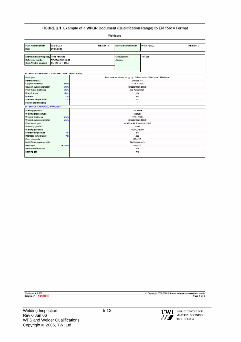
Welding Inspection 5.12 Rev 0 Jun 06 WPS and Welder Qualifications Copyright © 2006, TWI Ltd
WORLD CENTRE FOR MATERIALS JOINING TECHNOLOGY

Welding Inspection 5.13 Rev 0 Jun 06 WPS and Welder Qualifications Copyright © 2006, TWI Ltd
WORLD CENTRE FOR MATERIALS JOINING TECHNOLOGY

Figure 2 Example of WPQR Document to EN 15614 Format Welding Inspection 5.14 Rev 0 Jun 06 WPS and Welder Qualifications Copyright © 2006, TWI Ltd
WORLD CENTRE FOR MATERIALS JOINING TECHNOLOGY

Figure 3 Example of Welder Qualification Test Certificate to EN 287 Format
Welding Inspection 5.15 Rev 0 Jun 06 WPS and Welder Qualifications Copyright © 2006, TWI Ltd
WORLD CENTRE FOR MATERIALS JOINING TECHNOLOGY

Welding Inspection Rev 0 Jun 06 Copyright © 2006, TWI Ltd
WORLD CENTRE FOR MATERIALS JOINING TECHNOLOGY
Section 06
Materials Inspection

Welding Inspection 6.1 Rev 0 Jun 06 Materials Inspection Copyright © 2006, TWI Ltd
WORLD CENTRE FOR MATERIALS JOINING TECHNOLOGY
6.0 MATERIALS INSPECTION 6.1 GENERAL
One of the duties of the Visual/Welding Inspector is to carry out materials inspection. There are a number of situations where the inspector will be required to carry out materials inspection:
• at the plate or pipe mill, • of material during fabrication or construction • of material after installation, usually during a planned maintenance programme,
outage or shutdown.
A wide range of materials are available, that can be used in fabrication and welding. These include, but are not limited to:
• Steels • Stainless steels • Aluminium and its alloys • Nickel and its alloys • Copper and its alloys • Titanium and its alloys • Cast iron These materials are all widely used in fabrication, welding and construction to meet the requirements of a diverse range of applications and industry sectors.
There are three essential aspects to materials inspection that the Inspector should
consider:
1. Material type and weldability 2. Material traceability 3. Material condition and dimensions. 6.2 MATERIAL TYPES AND WELDABILITY A Welding Inspector must be able to understand and interpret the material designation in order to check compliance with relevant normative documents. For example materials standards such as BS EN, API, ASTM, the Welding Procedure Specification (WPS), the purchase order, fabrication drawings, the quality plan / the contract specification and client requirements. A commonly used material standard for steel designation is BS EN 10025 – Hot rolled products of non-alloy structural steels.

Welding Inspection 6.2 Rev 0 Jun 06 Materials Inspection Copyright © 2006, TWI Ltd
WORLD CENTRE FOR MATERIALS JOINING TECHNOLOGY
A typical steel designation to this standard, S355J2G3, would be classified as follows: S Structural Steel 355 Minimum Yield Strength: N/mm² at t ≤ 16mm J2 Longitudinal Charpy, 27Joules 6 - 20°C G3 Normalised or normalised rolled In terms of material type and weldability, commonly used materials and most alloys of these materials can be fusion welded using various welding processes, in a wide range of thickness, and, where applicable, diameters.
Reference to other standards such as ISO 15608 Welding - Guidelines for a metallic material grouping system, steel producer’s and welding consumable data books can also provide the Inspector with guidance on the suitability of a material and consumable type for a given application. 6.3 MATERIAL TRACEABILITY
Traceability is defined as “ the ability to trace the history, application or location of that which is under consideration” In the case of a welded product, traceability may require the Inspector to consider: • The origin of the materials – both parent and filler material • The processing history – for example before or after PWHT • The location of the product – this would usually refer to a specific part or sub-
assembly In order to trace the history of the material, reference to the inspection documents must be made. BSEN 10204 Metallic products – Types of inspection documents is the standard, which provides guidance on these types of document. Under BSEN 10204 inspection documents fall into two types: Non-Specific Inspection (a) Inspection carried out by the manufacturer in accordance with his own procedures to assess whether products defined by the same product specification and made by the same manufacturing process, are in compliance with the requirements of the order or not. Type 2.1 are documents in which the manufacturer declares that the products supplied are in compliance with the requirements of the order without inclusion of test results.
Type 2.2 are documents in which the manufacturer declares that the products supplied are in compliance with the requirements of the order and in which test results based on non-specific inspection are supplied.

Welding Inspection 6.3 Rev 0 Jun 06 Materials Inspection Copyright © 2006, TWI Ltd
WORLD CENTRE FOR MATERIALS JOINING TECHNOLOGY
Specific Inspection (b) Inspection carried out, before delivery, according to the product specification, on the products to be supplied or on test units of which the products supplied are part, in order to verify that these products are in compliance with the requirements of the order.
Type 3.1 are documents in which the manufacturer declares that the products supplied are in compliance with the requirements of the order and in which test results are supplied.
Type 3.2 are documents prepared by both the manufacturer’s authorised inspection representative independent of the manufacturing department, and either the purchaser’s authorised representative or the inspector designated by the official regulations, and in which they declare that the products supplied are in compliance with the requirements of the order and in which test results are supplied.
Application or location of a particular material can be carried out through a review of the Welding Procedure Specification (WPS), the fabrication drawings, the quality plan or by physical inspection of the material at the point of use.
In certain circumstances the Inspector may have to witness the transfer of cast numbers from the original plate to a piece to be used in production, for example run on run off plates that are to be used for Procedure Qualification Tests.
On pipeline work it is a requirement that the inspector records all the relevant
information for each piece of line pipe. On large diameter pipes this information is usually stencilled on the inside of the pipe. On smaller diameter pipes the information may be stencilled along the outside of the pipe.

BS EN 10204: METALLIC MATERIALS TYPES OF INSPECTION DOCUMENTS SUMMARY.
NON – SPECIFIC INSPECTION * (a)
Welding Inspection 6.4 Rev 0 Jun 06 Materials Inspection Copyright © 2006, TWI Ltd
WORLD CENTRE FOR MATERIALS JOINING TECHNOLOGY
a) Non-specific inspection may be replaced by specific inspection if specified in the material standard or the order.
b) Quality management system of the material manufacturer certified by a competent body established within the community and having undergone a specific assessment for materials
IInnssppeeccttiioonn ddooccuummeenntt ttyyppee 22..11DDeeccllaarraattiioonn ooff ccoommpplliiaannccee wwiitthh tthhee oorrddeerr SSttaatteemmeenntt ooff ccoommpplliiaannccee wwiitthh tthhee oorrddeerr.. Validated by the manufacturer.
Inspection document type 2.2 TTeesstt rreeppoorrtt SSttaatteemmeenntt ooff ccoommpplliiaannccee wwiitthh tthhee oorrddeerr,, wwiitthh iinnddiiccaattiioonn ooff rreessuullttss ooff nnoonn--ssppeecciiffiicc iinnssppeeccttiioonn.. VVaalliiddaatteedd bbyy tthhee mmaannuuffaaccttuurreerr
SPECIFIC INSPECTION * (b)
IInnssppeeccttiioonn cceerrttiiffiiccaattee ttyyppee 33..22 SSttaatteemmeenntt ooff ccoommpplliiaannccee wwiitthh tthhee oorrddeerr,, wwiitthh iinnddiiccaattiioonn ooff rreessuullttss ooff ssppeecciiffiicc iinnssppeeccttiioonn.. VVaalliiddaatteedd bbyy tthhee mmaannuuffaaccttuurreerr’’ss aauutthhoorriisseedd iinnssppeeccttiioonn rreepprreesseennttaattiivvee iinnddeeppeennddeenntt ooff tthhee mmaannuuffaaccttuurriinngg ddeeppaarrttmmeenntt aanndd eeiitthheerr tthhee ppuurrcchhaasseerr’’ss aauutthhoorriisseedd iinnssppeeccttiioonn rreepprreesseennttaattiivvee oorr tthhee iinnssppeeccttoorr ddeessiiggnnaatteedd bbyy tthhee ooffffiicciiaall rreegguullaattiioonnss..
IInnssppeeccttiioonn cceerrttiiffiiccaattee ttyyppee 33..11 SSttaatteemmeenntt ooff ccoommpplliiaannccee wwiitthh tthhee oorrddeerr,, wwiitthh iinnddiiccaattiioonn ooff rreessuullttss ooff ssppeecciiffiicc iinnssppeeccttiioonn VVaalliiddaatteedd bbyy tthhee mmaannuuffaaccttuurreerr’’ss aauutthhoorriisseedd iinnssppeeccttiioonn rreepprreesseennttaattiivvee iinnddeeppeennddeenntt ooff tthhee mmaannuuffaaccttuurriinngg ddeeppaarrttmmeenntt..
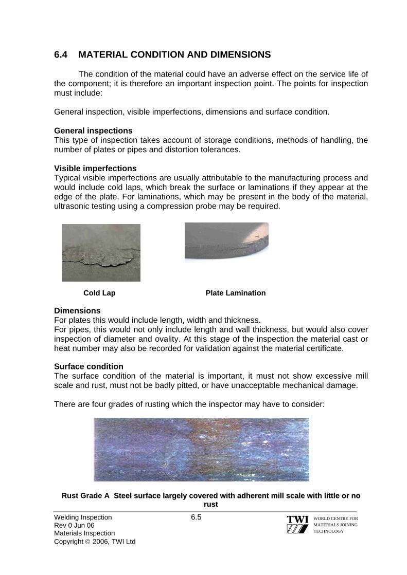
6.4 MATERIAL CONDITION AND DIMENSIONS
The condition of the material could have an adverse effect on the service life of the component; it is therefore an important inspection point. The points for inspection must include:
General inspection, visible imperfections, dimensions and surface condition. General inspections This type of inspection takes account of storage conditions, methods of handling, the number of plates or pipes and distortion tolerances. Visible imperfections Typical visible imperfections are usually attributable to the manufacturing process and would include cold laps, which break the surface or laminations if they appear at the edge of the plate. For laminations, which may be present in the body of the material, ultrasonic testing using a compression probe may be required. Cold Lap Plate Lamination Dimensions For plates this would include length, width and thickness. For pipes, this would not only include length and wall thickness, but would also cover inspection of diameter and ovality. At this stage of the inspection the material cast or heat number may also be recorded for validation against the material certificate. Surface condition The surface condition of the material is important, it must not show excessive mill scale and rust, must not be badly pitted, or have unacceptable mechanical damage. There are four grades of rusting which the inspector may have to consider:
Welding Inspection 6.5 Rev 0 Jun 06 Materials Inspection Copyright © 2006, TWI Ltd
WORLD CENTRE FOR MATERIALS JOINING TECHNOLOGY
Rust Grade A SStteeeell ssuurrffaaccee llaarrggeellyy ccoovveerreedd wwiitthh aaddhheerreenntt mmiillll ssccaallee wwiitthh lliittttllee oorr nnoo
rruusstt

Welding Inspection 6.6 Rev 0 Jun 06 Materials Inspection Copyright © 2006, TWI Ltd
WORLD CENTRE FOR MATERIALS JOINING TECHNOLOGY
RRuusstt GGrraaddee BB SStteeeell ssuurrffaaccee,, wwhhiicchh hhaass bbeegguunn ttoo rruusstt,, aanndd ffrroomm wwhhiicchh mmiillll ssccaallee hhaass
bbeegguunn ttoo ffllaakkee..
RRuusstt GGrraaddee CC SStteeeell ssuurrffaaccee oonn wwhhiicchh tthhee mmiillll ssccaallee hhaass rruusstteedd aawwaayy oorr ffrroomm wwhhiicchh iitt oonn..
ccaann bbee ssccrraappppeedd.. SSlliigghhtt ppiittttiinngg vviissiibbllee uunnddeerr nnoorrmmaall vviissii
RRuusstt GGrraaddee DD SStteeeell ssuurrffaaccee oonn wwhhiicchh mmiillll ssccaallee hhaass rruusstteedd aawwaayy.. GGeenneerraall ppiittttiinngg vviissiibbllee uunnddeerr nnoorrmmaall vviissiioonn..
6.5
Material inspection is an important part of the Inspector’s duties and an unders
pection required and the oint at which inspection takes place. Reference to a fabrication drawing should
provide information on the type and location of the material.
SUMMARY
tanding of the documentation involved is the key to success.
Material inspection must be approached in a logical and precise manner if material verification and traceability is to be achieved. This can be difficult if the material is not readily accessible, access may have to be provided, safety precautions observed and authorisation obtained before material inspection can be carried out. Reference to the quality plan should identify the level of insp

Welding Inspection 6.7 Rev 0 Jun 06 Materials Inspection Copyright © 2006, TWI Ltd
WORLD CENTRE FOR MATERIALS JOINING TECHNOLOGY
document is missing, other methods of identifying the material may eed to be used.
order to verify compliance with the purchase order or ppropriate standard(s).
EN ISO 9000 Quality management systems – Fundamentals and vocabulary
.
If material type cannot be determined from the inspection documents available, or if the inspectionn
These methods may include but are not limited to: spark test, spectroscopic analysis, chemical analysis, scleroscope hardness test etc. These types of tests are normally conducted by an approved test house, and the Inspector may be required to witness these tests in a *

Welding Inspection Rev 0 Jun 06 Copyright © 2006, TWI Ltd
WORLD CENTRE FOR MATERIALS JOINING TECHNOLOGY
Section 07
Codes & Standards
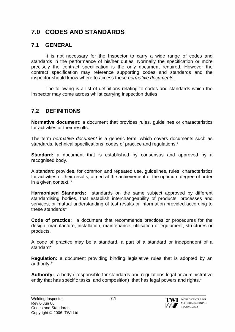
Welding Inspector 7.1 Rev 0 Jun 06 Codes and Standards Copyright © 2006, TWI Ltd
WORLD CENTRE FOR MATERIALS JOINING TECHNOLOGY
7.0 CODES AND STANDARDS 7.1 GENERAL
It is not necessary for the Inspector to carry a wide range of codes and standards in the performance of his/her duties. Normally the specification or more precisely the contract specification is the only document required. However the contract specification may reference supporting codes and standards and the inspector should know where to access these normative documents.
The following is a list of definitions relating to codes and standards which the Inspector may come across whilst carrying inspection duties 7.2 DEFINITIONS Normative document: a document that provides rules, guidelines or characteristics for activities or their results. The term normative document is a generic term, which covers documents such as standards, technical specifications, codes of practice and regulations.* Standard: a document that is established by consensus and approved by a recognised body. A standard provides, for common and repeated use, guidelines, rules, characteristics for activities or their results, aimed at the achievement of the optimum degree of order in a given context. * Harmonised Standards: standards on the same subject approved by different standardising bodies, that establish interchangeability of products, processes and services, or mutual understanding of test results or information provided according to these standards* Code of practice: a document that recommends practices or procedures for the design, manufacture, installation, maintenance, utilisation of equipment, structures or products. A code of practice may be a standard, a part of a standard or independent of a standard* Regulation: a document providing binding legislative rules that is adopted by an authority.* Authority: a body ( responsible for standards and regulations legal or administrative entity that has specific tasks and composition) that has legal powers and rights.*

Welding Inspector 7.2 Rev 0 Jun 06 Codes and Standards Copyright © 2006, TWI Ltd
WORLD CENTRE FOR MATERIALS JOINING TECHNOLOGY
Regulatory authority: authority that is responsible for preparing or adopting regulations* Enforcement authority: authority that is responsible for enforcing regulations* Specification: document stating requirements. Meaning full data and its supporting medium stating needs or expectations that is stated, generally implied or obligatory.** Procedure: specified way to carry out an activity or a process*. Usually it is a written description of all essential parameters and precautions to be observed when applying a technique to a specific application following an established standard, code or specification Instruction: a written description of the precise steps to be followed, based on an established procedure, standard, code or specification. Quality Plan: a document specifying which procedures and associated resources shall be applied by whom and when to a specific project, product, process or contract* * ISO IEC Guide 2 – Standardisation and related activities – General vocabulary ** EN ISO 9000 – 2000 – Quality management systems – Fundamentals and vocabulary
7.3 SUMMARY
Application standards and codes of practice ensure that a structure or component will have an acceptable level of quality and be fit for the intended purpose. Applying the requirements of a standard, code of practice or specification can be a problem for the inexperienced Inspector. Confidence in applying the requirements of one or all of these documents to a specific application only comes with use over a period of time.
If in doubt the Inspector must always refer to a higher authority in order to avoid confusion and potential problems.
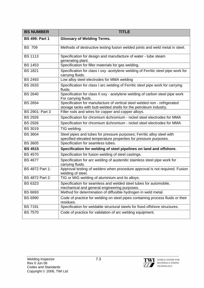
Welding Inspector 7.3 Rev 0 Jun 06 Codes and Standards Copyright © 2006, TWI Ltd
WORLD CENTRE FOR MATERIALS JOINING TECHNOLOGY
BS NUMBER TITLE BS 499: Part 1
Glossary of Welding Terms.
BS 709
Methods of destructive testing fusion welded joints and weld metal in steel.
BS 1113
Specification for design and manufacture of water - tube steam generating plant.
BS 1453 Specification for filler materials for gas welding. BS 1821
Specification for class I oxy -acetylene welding of Ferritic steel pipe work for carrying fluids.
BS 2493 Low alloy steel electrodes for MMA welding BS 2633
Specification for class I arc welding of Ferritic steel pipe work for carrying fluids.
BS 2640
Specification for class II oxy - acetylene welding of carbon steel pipe work For carrying fluids.
BS 2654
Specification for manufacture of vertical steel welded non - refrigerated storage tanks with butt-welded shells for the petroleum industry.
BS 2901: Part 3 Filler rods and wires for copper and copper alloys. BS 2926 Specification for chromium &chromium - nickel steel electrodes for MMA BS 2926 Specification for chromium &chromium - nickel steel electrodes for MMA BS 3019 TIG welding. BS 3604 Steel pipes and tubes for pressure purposes; Ferritic alloy steel with
specified elevated temperature properties for pressure purposes. BS 3605 Specification for seamless tubes. BS 4515 Specification for welding of steel pipelines on land and offshore. BS 4570 Specification for fusion welding of steel castings. BS 4677 Specification for arc welding of austenitic stainless steel pipe work for
carrying fluids. BS 4872 Part 1: Approval testing of welders when procedure approval is not required. Fusion
welding of steel. BS 4872 Part 2: TIG or MIG welding of aluminium and its alloys. BS 6323 Specification for seamless and welded steel tubes for automobile,
mechanical and general engineering purposes. BS 6693 Method for determination of diffusible hydrogen in weld metal. BS 6990 Code of practice for welding on steel pipes containing process fluids or their
residues. BS 7191 Specification for weldable structural steels for fixed offshore structures. BS 7570 Code of practice for validation of arc welding equipment.

Welding Inspector 7.4 Rev 0 Jun 06 Codes and Standards Copyright © 2006, TWI Ltd
WORLD CENTRE FOR MATERIALS JOINING TECHNOLOGY
BS EN NUMBER TITLE BS EN 287 Part 1: Qualification test of welders - Fusion welding - Steels. BS EN 440 Wire electrodes and deposits for gas shielded metal arc of non - alloy
and fine grain steels. BS EN 499 Covered electrodes for manual metal arc welding of non – alloy and fine
grain steels. BS EN 3834-Parts 1 to 5
Quality requirements for fusion welding of metallic materials
BS EN 756 Wire electrodes and flux wire combinations for submerged arc welding of non - alloy and fine grain steels.
BS EN 760 Fluxes for submerged arc welding. BS EN 970 Non - destructive examination of fusion welds - visual examination. BS EN 910 Destructive tests on welds in metallic materials - Bend tests. BS EN 12072 Filler rods and wires for stainless steels. BS EN ISO 18274 Aluminium and aluminium alloys & magnesium alloys. Nickel & nickel alloys
Note: The Inspector should have an awareness of standards that are printed in bold.
BS EN NUMBER TITLE BS EN 1011 Part 1: Part 2: Part 3 Part 4.
Welding recommendations for welding of metallic materials. General guidance for arc welding. Arc welding of Ferritic steels. Arc welding of stainless steels Arc welding of aluminium and aluminium alloys.
EN 1320 Destructive tests on welds in metallic materials. EN 1435 Non-destructive examination of welds - Radiographic examination of welded
joints. BS EN 10002 Tensile testing of metallic materials. BS EN 10020 Definition and classification of grades of steel. BS EN 10027 Designation systems for steels. BS EN 10045 Charpy impact tests on metallic materials. BS EN 10204 Metallic products - Types of inspection documents. BS EN 22553 Welded, brazed and soldered joints - Symbolic representation on
drawings. BS EN 24063 Welding, brazing, soldering and braze welding of metal. Nomenclature
of processes and reference numbers for symbolic representation on drawings.
BS EN 25817 Arc welded joints in steel. Guidance on quality levels for imperfections.
BS EN 26520 Classification of imperfections in metallic fusion welds, with explanations.
BS EN 26848 Specification for tungsten electrodes for inert gas shielded arc welding and for plasma cutting and welding.

Welding Inspector 7.5 Rev 0 Jun 06 Codes and Standards Copyright © 2006, TWI Ltd
WORLD CENTRE FOR MATERIALS JOINING TECHNOLOGY
ISO NUMBER: TITLE:
ISO 857 - 1 Welding and allied processes - Vocabulary - Part 1 - Metal welding processes.
ISO 6947 Welds - Working positions - Definitions of angles of slope and rotation. ISO 9606 – 2 Qualification test of welders – Fusion welding.
Part 2 Aluminium & aluminium Alloys. ISO 15607 Specification and qualification of welding procedures for metallic materi
General rules. ISO 15608 Welding - Guidelines for a metallic material grouping system. ISO 15609 - 1 Specification and qualification of welding procedures for metallic materi
Welding procedure specification - Part 1: Arc welding. ISO 15610 Specification and qualification of welding procedures for metallic materials-
Qualification based on tested welding consumables. ISO 15611 Specification and qualification of welding procedures for metallic materials-
Qualification based on previous welding experience. ISO 15613 Specification and qualification of welding procedures for metallic materials -
Qualification based on pre - production-welding test. ISO 15614 Specification and qualification of welding procedures for metallic materi
Welding procedure test.
Part 1: Part 2 Part 3 Part 4 Part 5 Part 6 Part 7 Part 8 Part 9 Part 10 Part 11 Part 12 Part 13
Arc and gas welding of steels and arc welding of nickel and nickel alloys. Arc welding of aluminium and its alloys* Welding procedure tests for the arc welding of cast irons* Finishing welding of aluminium castings* Arc welding of titanium, zirconium and their alloys. Copper and copper alloys* Not used Welding of tubes to tube-plate joints. Underwater Hyperbaric wet welding* Hyperbaric dry welding* Electron and laser beam welding Spot, seam and projection welding* Resistance butt and flash welding*
Note: The Inspector should have an awareness of standards that are printed in bold. *Proposed
.

Welding Inspection Rev 0 Jun 06 Copyright © 2006, TWI Ltd
WORLD CENTRE FOR MATERIALS JOINING TECHNOLOGY
Section 08
Welding Symbols

8.0 WELDING SYMBOLS
A weld joint can be represented on an engineering drawing by means of a detailed sketch showing every detail and dimension of the joint preparation - as shown below.
8-12°
Welding Inspector 8.1 Rev 0 Jun 06 Welding Symbols Copyright © 2006, TWI Ltd
WORLD CENTRE FOR MATERIALS JOINING TECHNOLOGY
R6≈
While this method of representation gives comprehensive information, it can be time consuming and can also ‘overburden’ the drawing.
An alternative method is to use a symbolic representation to specify the required information - as shown below for the same joint detail.
Symbolic representation has following advantages: • simple and quick to put on the drawing
• does not over-burden the drawing
• no need for an additional view - all welding symbols can be put on the main assembly drawing Symbolic representation has following disadvantages: • it can only be used for standard joints (e.g., BS EN ISO 9692)
• there is not a way of giving precise dimensions for joint details
• some training is necessary in order to interpret the symbols correctly
1-4mm
1-3mm
Single-U preparation

Welding Inspector 8.2 Rev 0 Jun 06 Welding Symbols Copyright © 2006, TWI Ltd
WORLD CENTRE FOR MATERIALS JOINING TECHNOLOGY
8.1 STANDARDS FOR SYMBOLIC REPRESENTATION OF WELDED JOINTS ON DRAWINGS
There are two principal standards that are used for welding symbols, namely: European Standard EN22553 – Welded, brazed & soldered joints – Symbolic representation on drawings American Standard AWS A2.4 – Standard Symbols for Welding, Brazing, & Non-destructive Examination
These standards are very similar in many respects, but there are also some major differences that need to be understood to avoid misinterpretation.
Details of the European Standard are given in the following sub-sections with only brief information about how the American Standard differs from the European Standard. Elementary Welding Symbols
Various types of weld joint are represented by a symbol that is intended to help
interpretation by being similar to the shape of the weld to be made. Examples of symbols used by EN 22553 are shown on following pages.

8.2 ELEMENTARY WELDING SYMBOLS
Designation Illustration of joint preparation Symbol
Square butt weld
Single-V butt weld
Single-bevel butt weld
Single-V butt weld with broad root face
Single-bevel butt weld with broad root face
Single-U butt weld
Single-J butt weld
Fillet weld
Surfacing (cladding)
Backing run (back or backing weld)
Welding Inspector 8.3 Rev 0 Jun 06 Welding Symbols Copyright © 2006, TWI Ltd
WORLD CENTRE FOR MATERIALS JOINING TECHNOLOGY
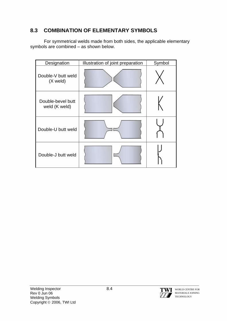
8.3 COMBINATION OF ELEMENTARY SYMBOLS
For symmetrical welds made from both sides, the applicable elementary symbols are combined – as shown below.
Designation Illustration of joint preparation Symbol
Double-V butt weld (X weld)
Double-bevel butt weld (K weld)
Double-U butt weld
Double-J butt weld
Welding Inspector 8.4 Rev 0 Jun 06 Welding Symbols Copyright © 2006, TWI Ltd
WORLD CENTRE FOR MATERIALS JOINING TECHNOLOGY

8.4 SUPPLEMENTARY SYMBOLS
Weld symbols may be complemented by a symbol to indicate the required shape of the weld. Examples of supplementary symbols and how they are applied are given below.
Designation Illustration of joint preparation Symbol
Flat (flush) single-V butt weld
Convex double-V butt weld
Concave fillet weld
Flat (flush) single-V butt weld with flat (flush) backing run
Welding Inspector 8.5 Rev 0 Jun 06 Welding Symbols Copyright © 2006, TWI Ltd
WORLD CENTRE FOR MATERIALS JOINING TECHNOLOGY
Single-V butt weld with broad root face and backing run
Fillet weld with both toes blended smoothly
Note: If the weld symbol does not have a supplementary symbol then the shape of the weld surface does not need to be indicated precisely.

8.5 POSITION OF SYMBOLS ON DRAWINGS
In order to be able to provide comprehensive details for weld joints, it is necessary to distinguish the two sides of the weld joint. The way this is done, according to EN 22553, is by means of: • an arrow line • a dual reference line consisting of a continuous line and a dashed line The schematic below illustrates the method of representation.
Welding Inspector 8.6 Rev 0 Jun 06 Welding Symbols Copyright © 2006, TWI Ltd
WORLD CENTRE FOR MATERIALS JOINING TECHNOLOGY
2a
joint line
1
2b
1 = arrow line 2a = reference line (continuous line) 2b = identification line (dashed line) 3 = welding symbol (single-V joint)
3
8.6 RELATIONSHIP BETWEEN THE ARROW LINE AND THE JOINT LINE
One end of the joint line is called the arrow side and the opposite end is called other side.
The arrow side is always the end of the joint line that the arrow line points to (and touches).
It can be at either end of the joint line and it is the draughtsman who decides which end to make the arrow side.

The schematic below illustrates these principles.
‘arrow side’
‘arrow side’
arrow line
‘other side’
arrow line
‘other side’
arrow line
‘arrow side’ ‘other side’
arrow line
‘other side’ ‘arrow side’
There are some conventions about the arrow line, namely: • it must touch one end of the joint line • it joins one end of the continuous reference line such that it forms an angle with
it
In case of a non-symmetrical joint, such as a single bevel joint, the arrow line must point towards the joint member that will have the weld preparation put on to it (as shown below) An example of how a single-bevel butt joint should be represented is shown below.
Welding Inspector 8.7 Rev 0 Jun 06 Welding Symbols Copyright © 2006, TWI Ltd
WORLD CENTRE FOR MATERIALS JOINING TECHNOLOGY
8.7 POSITION OF THE REFERENCE LINE AND POSITION OF THE WELD SYMBOL
The reference line should, wherever possible, be drawn parallel to the bottom edge of the drawing (or perpendicular to it).
For a non-symmetrical weld it is essential that the arrow side and other side of the weld be distinguished. The convention for doing this is as follows:

• symbols for the weld details required on the arrow side must be placed on the continuous line
• symbols for the weld details on other side must be placed on the dashed line
This convention is illustrated below for a single-V joint with a backing run.
Welding Inspector 8.8 Rev 0 Jun 06 Welding Symbols Copyright © 2006, TWI Ltd
WORLD CENTRE FOR MATERIALS JOINING TECHNOLOGY
arrow side
arrow side
other side
other side
or

8.8 POSITIONS OF THE CONTINUOUS LINE AND THE DASHED LINE
EN 22553 allows the dashed line to be either above or below the continuous line – as shown below. or
If the weld is a symmetrical weld then it is not necessary to distinguish between the two sides and EN 22553 states that the dashed line should be omitted. Thus, a single-V butt weld with a backing run can be shown by either of the four symbolic representations shown below. single-V weld with a backing run other sidearrow side arrow side other side
Welding Inspector 8.9 Rev 0 Jun 06 Welding Symbols Copyright © 2006, TWI Ltd
WORLD CENTRE FOR MATERIALS JOINING TECHNOLOGY
Note: This ‘flexibility’ re the position of the continuous and dashed lines is an interim
measure that EN 22553 allows so that old drawings (to the obsolete BS499 Part 2, for example) can be conveniently converted to show the EN method of representation.
arrow side
arrow side
other side
other side

8.9 DIMENSIONING OF WELDS General rules
Dimensions may need to be specified for some types of weld and EN 22553 specifies a convention for this. • dimensions for the cross-section of the weld are written on the left-hand side of
the symbol • length dimensions for the weld are written on the right-hand side of the symbol • the absence of any indication to the contrary, all butt welds are full penetration
welds 8.9.1 SYMBOLS FOR CROSS-SECTION DIMENSIONS The following letters are used to indicate dimensions: a fillet weld throat thickness Z fillet weld leg length s penetration depth (applicable to partial penetration butt welds & deep penetration fillets) Some examples of how these symbols are used are shown below.
Welding Inspector 8.10 Rev 0 Jun 06 Welding Symbols Copyright © 2006, TWI Ltd
WORLD CENTRE FOR MATERIALS JOINING TECHNOLOGY
s10
Partial penetration single-V butt weld 10mm
Z8 Fillet weld with 8mm leg
8mm

a6
Fillet weld with 6mm throat
6mm
8.9.2 SYMBOLS FOR LENGTH DIMENSIONS
To specify weld length dimensions and, for intermittent welds the number of individual weld lengths (weld elements), the following letters are used: - individual weld lengths (weld elements), the following letters are used: - l length of weld l length of weld (e) distance between adjacent weld elements (e) distance between adjacent weld elements
n number of weld elements n number of weld elements
The use of these letters is illustrated for the intermittent double-sided fillet weld shown below.
The use of these letters is illustrated for the intermittent double-sided fillet weld shown below.
Welding Inspector 8.11 Rev 0 Jun 06 Welding Symbols Copyright © 2006, TWI Ltd
WORLD CENTRE FOR MATERIALS JOINING TECHNOLOGY
100mm
8
END VIEW PLAN VIEW150mm
Z8 3 Z8
× 150 (100) 3 × 150 (100)
Note: dashed line not required because it is a symmetrical weld
z n × l (e)
z n × l (e)

If an intermittent double-sided fillet weld is to be staggered, the convention for indicating this is shown below.
l (e)
z
END VIEW PLAN VIEW
Welding Inspector 8.12 Rev 0 Jun 06 Welding Symbols Copyright © 2006, TWI Ltd
WORLD CENTRE FOR MATERIALS JOINING TECHNOLOGY
8.9.3 COMPLEMENTARY INDICATIONS
Complementary indications may be needed to specify some other characteristics of welds. Examples of these are given as follows: - • Field or site welds is indicated by a flag • A peripheral weld, to be made all around a part, is indicated by a circle
z n× l (e)z n× l (e)

8.10 INDICATION OF THE WELDING PROCESS
If required, the welding process is to be symbolised by a number written between the two branches of a fork at the end of the reference line – as shown below.
Some Welding Process Designations
111 = MMA 121 = SAW 131 = MIG 135 = MAG
111 8.11 OTHER INFORMATION IN THE TAIL OF THE REFERENCE LINE
In addition to specifying the welding process, other information can be added to an open tail (shown above) such as the NDT acceptance level the working position and the filler metal type and EN 22553 defines the sequence that must be used for this information.
A closed tail can also be used into which reference to a specific instruction can be added – as shown below.
WPS 014 8.12 WELD SYMBOLS IN ACCORDANCE WITH AWS 2.4
Many of the symbols and conventions that are specified by EN 22553 are the same as those used by AWS. The major differences are: • only one reference line is used (a continuous line) • symbols for weld details on the arrow side go underneath the reference line • symbols for weld details on the other side go on top of the reference line
Welding Inspector 8.13 Rev 0 Jun 06 Welding Symbols Copyright © 2006, TWI Ltd
WORLD CENTRE FOR MATERIALS JOINING TECHNOLOGY

These differences are illustrated by the following example.
Welding Inspector 8.14 Rev 0 Jun 06 Welding Symbols Copyright © 2006, TWI Ltd
WORLD CENTRE FOR MATERIALS JOINING TECHNOLOGY
arrow side other side .
Welding Inspection Rev 0 Jun 06 Copyright © 2006, TWI Ltd
WORLD CENTRE FOR MATERIALS JOINING TECHNOLOGY
Section 09
Introduction to Welding Processes

Welding Inspection 9.1 Rev 0 Jun 06 Introduction to Welding Processes Copyright © 2006, TWI Ltd
WORLD CENTRE FOR MATERIALS JOINING TECHNOLOGY
9.0 INTRODUCTION TO WELDING PROCESSES 9.1 GENERAL Common characteristics of the four main arc-welding processes, MMA, TIG, MIG/MAG & SAW are:
An arc is created when an electrical discharge occurs across the gap between an electrode and parent metal
The discharge causes a spark to form and the spark causes the surrounding
gas to ionise
the ionised gas enables a current to flow across the gap between electrode and base metal thereby creating an arc
the arc generates heat for fusion of the base metal
With the exception of TIG welding, the heat generated by the arc also causes
the electrode surface to melt and molten droplets can transfer to the weld pool to form a weld bead or weld run
Heat input to the fusion zone depends on the arc voltage, arc current and
welding/travel speed 9.2 PRODUCTIVITY If the items to be welded can be manipulated, so that welding can be done in the flat position, higher rates of metal deposition can be used which will increase productivity.
For consumable electrode welding processes, the rate of transfer of molten metal to the weld pool is directly related to the welding current density (the ratio of the current to the diameter of the electrode).
For TIG welding, the higher the current, the more energy there is for fusion and thus the higher the rate at which the filler wire can be added to the weld pool.

Welding Inspection 9.2 Rev 0 Jun 06 Introduction to Welding Processes Copyright © 2006, TWI Ltd
WORLD CENTRE FOR MATERIALS JOINING TECHNOLOGY
9.3 HEAT INPUT Heat input (HI) for arc welding is calculated from the following formula:
HI = Volts x Amps Travel Speed x 1000
units for formula: travel speed in mm/second heat input is given in kJ/mm Heat input is mainly influenced by the travel speed. Welding position and the welding process have a major influence on the travel speed that can be used For manual and semi-automatic welding the following are general principles: vertical-up progression tends to give the highest heat input because there is
need to ‘weave’ to get suitable profile and the forward travel speed is relatively slow
vertical-down welding tends to give the lowest heat input because of the fast
travel speed that can be used horizontal-vertical welding is a relatively low heat input welding position
because the welder cannot ‘weave’ in this position overhead welding tends to give low heat input because of the need to use low
current and relatively fast travel speed welding in the flat position (downhand) can be a low or high heat input position
because the welder has more flexibility about the travel speed that can be used of the arc welding processes, SAW has potential to give the highest heat input
and the highest deposition rates and TIG & MIG/MAG can produce very low heat input.
Typical heat input values for controlled heat input welding will tend to be in the
range ~1.0 to ~3.5 kJ/mm. 9.4 WELDING PARAMETERS Arc Voltage Arc voltage is related to the arc length.

Welding Inspection 9.3 Rev 0 Jun 06 Introduction to Welding Processes Copyright © 2006, TWI Ltd
WORLD CENTRE FOR MATERIALS JOINING TECHNOLOGY
For processes where the arc voltage is controlled by the power source (SAW, MIG/MAG & FCAW) and can be varied independently from the current, the voltage setting will affect the profile of the weld. As welding current is raised, the voltage also needs to be raised to ‘spread’ the weld metal and produce a wider and flatter deposit. For MIG/MAG, arc voltage has a major influence on droplet transfer across the arc. Welding Current Welding current has a major influence on the depth of fusion/penetration of into the base metal and adjacent weld runs. As a general rule, the higher the current the greater the depth of penetration. Penetration depth affects dilution of the weld deposit by the parent metal and it is particularly important to control this when dissimilar metals are joined. Polarity Polarity determines whether most of the arc energy (‘the heat’) is concentrated at the electrode surface or at the surface of the parent material. The location of ‘the heat’ with respect to polarity is not the same for all processes and the affects/options/benefits for each of the main arc welding processes are summarised below:
PROCESS
POLARITY
DC + VE DC - VE AC
MMA best
penetration less penetration but higher deposition rate (used for root passes and weld overlaying)
only suitable for some electrodes & when arc blow is a problem
TIG rarely used due
to tungsten overheating
used for all metals - except Al/Al alloys (& Mg/Mg alloys)
required for Al/Al alloys to ‘break-up’ the refractory oxide film
GMAW solid wires (MIG/MAG)
used for all metals and virtually all situations
not used
not used
FCAW/MCAW gas-shielded & self-shielded cored wires
most common
some positional basic fluxed wires are designed to run on -VE; some metal cored wires may also be used on -VE particularly for positional welding
not used
SAW
best penetration
less penetration but higher deposition rate (used for root passes and overlaying)
used to avoid arc blow – particularly for multi-electrode systems

Welding Inspection 9.4 Rev 0 Jun 06 Introduction to Welding Processes Copyright © 2006, TWI Ltd
WORLD CENTRE FOR MATERIALS JOINING TECHNOLOGY
9.5 POWER SOURCE CHARACTERISTICS In order to strike an arc; a relatively high voltage is required to generate a spark between the electrode and base metal. This is known as the open circuit voltage (OCV) and it is typically in the range from ~50 to ~ 90volts.
Once an arc has been struck and stabilised, there is a relationship between the arc voltage and the current flowing through the welding circuit that depends on the electrical characteristics of the power source.
This relationship is known as the power source static characteristic and power sources are manufactured to give a constant current or a constant voltage characteristic. 9.5.1 CONSTANT CURRENT POWER SOURCE This is the preferred type of power source for manual welding (MMA & manual TIG).
The volt-amp relationship for a constant current power source is shown in Figure 1. This shows the ‘no current’ position (the OCV) and from this point there are arc voltage/current curves that depend for the various current settings on the power source.
For manual welding (MMA & manual TIG) the welder sets the required current on the power source, but arc voltage is controlled by the arc length that the welder uses.
A welder has to work within a fairly narrow range of arc length for a particular current setting - if it is too long and the arc will extinguish and if it is too short and the electrode may ‘stub’ into the weld pool and the arc will be extinguished.
The operating principle of this type of power source is illustrated by reference to Figure 1.
The welder tries to hold a fairly constant arc length (B in Figure 1) for the current (Y) that has been set. However, he cannot keep the arc length constant and it will vary over a small working range (A to C in Figure 1) due to normal hand movement during welding.
The power source is designed to ensure that these small changes in arc voltage during normal welding will give only small changes in current (X to Z). Thus, the current can be considered to be essentially constant and this ensures that the welder is able to maintain control of fusion.
The ‘drooping’ shape of the volt-amp curves have led to constant current power sources sometimes being referred to as having a ‘drooping’ characteristic.

Welding Inspection 9.5 Rev 0 Jun 06 Introduction to Welding Processes Copyright © 2006, TWI Ltd
WORLD CENTRE FOR MATERIALS JOINING TECHNOLOGY
9.5.2 CONSTANT VOLTAGE POWER SOURCE This is the preferred type of power source for welding processes that have a wire feeder (MIG/MAG, FCAW and SAW). Wire feed speed and current are directly related so that as the current is increased the feed speed is increased and there is a corresponding increase in the burn-off rate to maintain the arc length/arc voltage.
The operating principle of this type of power source is illustrated by reference to Figure 2 A welder sets the voltage B and the current Y on the power source.
If the arc length is decreased to C (due to a variation in weld profile or as the welder’s hand moves up and down during semi-automatic welding) there will be a momentary increase in welding current to Z. The higher current Z, gives a higher burn-off rate and this brings the arc length (& arc voltage) back to the pre-set value.
Similarly, if the arc length increases the current quickly falls to X and the burn-off rate is reduced so that the arc length is brought back to the pre-set level B.
Thus, although the arc voltage does vary a little during welding the changes in current that restore the voltage to the pre-set value happen extremely quickly so that the voltage can be considered to remain constant.
The straight-line relationship between voltage and current and their relatively small gradient is the reason why this type of power source is often referred to as having a ‘flat characteristic’.
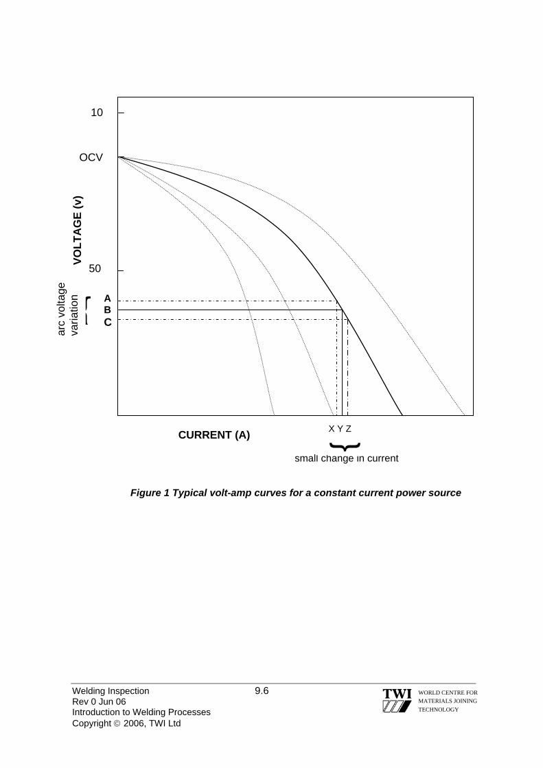
Welding Inspection 9.6 Rev 0 Jun 06 Introduction to Welding Processes Copyright © 2006, TWI Ltd
WORLD CENTRE FOR MATERIALS JOINING TECHNOLOGY
small change in current
{
{ AB C
10
CURRENT (A) X Y Z
VOLT
AG
E (v
) ar
c vo
ltage
va
riatio
n
50
OCV
Figure 1 Typical volt-amp curves for a constant current power source

Welding Inspection 9.7 Rev 0 Jun 06 Introduction to Welding Processes Copyright © 2006, TWI Ltd
WORLD CENTRE FOR MATERIALS JOINING TECHNOLOGY
OCV
X Y Z
A B C
VOLT
AG
E (v
)
{
arc
volta
ge
varia
tion
50
CURRENT (A)
large (momentary) change in current
10
Figure 2 Typical volt-amp curves for a constant voltage power source

Welding Inspection Rev 0 Jun 06 Copyright © 2006, TWI Ltd
WORLD CENTRE FOR MATERIALS JOINING TECHNOLOGY
Section 10
MMA Welding

10.0 MMA WELDING 10.1 MANUAL METAL-ARC / SHIELDED METAL ARC WELDING (MMA / SMAW). Manual metal arc welding (MMA) was first invented in Russia in 1888. It involved a bare metal rod with no flux coating to give a protective gas shield. The development of coated electrodes did not occur until the early 1900s, when the Kjellberg process was invented in Sweden and the Quasi-arc method was introduced in the UK.
The most versatile of the welding processes, manual metal arc welding is suitable for welding most ferrous and non-ferrous metals, over a wide range of thicknesses. The MMA welding process can be used in all positions, with reasonable ease of use and relatively economically. The final weld quality is primarily dependent on the skill of the welder.
When an arc is struck between the coated electrode and the work piece, both the electrode and work piece surface melt to form a weld pool. The average temperature of the arc is approximately 6000°C, which is sufficient to simultaneously melt the parent metal, the consumable core wire and the flux coating. The flux forms gas and slag, which protects the weld pool from oxygen and nitrogen in the surrounding atmosphere. The molten slag solidifies and cools and must be chipped off the weld bead once the weld run is complete (or before the next weld pass is deposited). The process allows only short lengths of weld to be produced before a new electrode needs to be inserted in the holder.
The Manual Metal Arc Welding Process.
Welding Inspection 10.1 Rev 0 Jun 06 MMA Welding Copyright © 2006, TWI Ltd
WORLD CENTRE FOR MATERIALS JOINING TECHNOLOGY

10.2 MANUAL METAL ARC WELDING BASIC EQUIPMENT REQUIREMENTS
1
2
1 0
5 6
4
3 8
9
7
1) Power source Transformer/Rectifier (Constant current type)
2) Holding oven (Holds at temperatures up to 150 °C)
3) Inverter power source. (More compact and portable)
4) Electrode holder (Of a suitable amperage rating)
5) Power cable (Of a suitable amperage rating)
6) Welding visor (With correct rating for the amperage/process)
7) Power return cable (Of a suitable amperage rating)
8) Electrodes (Of a suitable type & amperage rating)
9) Electrode oven (Bakes electrodes at up to 350 °C)
10) Control panel (On\Off/Amperage/Polarity/OCV)
Welding Inspection 10.2 Rev 0 Jun 06 MMA Welding Copyright © 2006, TWI Ltd
WORLD CENTRE FOR MATERIALS JOINING TECHNOLOGY

10.3 POWER REQUIREMENTS Manual Metal Arc welding can be carried out using either direct (DC) or alternating (AC) current. With DC welding current either positive (+ve) or negative (-ve) polarity can be used, so current is flowing in one direction. AC welding current flows from negative to positive, and is two directional.
Power sources for MMA welding are, either transformers (which transforms main AC to AC suitable for welding), transformer-rectifiers (which rectifies AC to DC), diesel or petrol driven generators (preferred for site work) or inverters (a more recent addition to welding power sources). For MMA welding a power source with A Constant Current (drooping) output characteristic must be used. The power source must provide: • An Open Circuit Voltage (OCV) to initiate the arc. Between 50 and 90 volts. • Welding Voltage to maintain the arc during welding. Between 20 and 30 volts • A suitable current range. Typically 30 –350amps • A stable arc. Rapid arc recovery or arc re-ignition without current surge. • A constant welding current. The arc length may change during welding, but
consistent electrode burn off rate and weld penetration characteristics must be maintained during welding.
10.4 WELDING VARIABLES Other factors, or welding variables, which affect the final quality of the MMA weld, are: Current (amperage) } Voltage } Affects Heat Input Travel speed } Polarity Type of electrode
EXAMPLES OF THE MMA WELDING PROCESS
Welding Inspection 10.3 Rev 0 Jun 06 MMA Welding Copyright © 2006, TWI Ltd
WORLD CENTRE FOR MATERIALS JOINING TECHNOLOGY
Welding Inspection 10.4 Rev 0 Jun 06 MMA Welding Copyright © 2006, TWI Ltd
WORLD CENTRE FOR MATERIALS JOINING TECHNOLOGY
10.4.1 CURRENT (AMPERAGE) The flow of electrons through the circuit is the welding current, measured in amperes (I). Amperage controls burn off rate and depth of penetration. Welding current level is determined by the size of electrode - manufacturers recommend the normal operating range and current Incorrect amperage settings when using MMA can contribute to the following: Amperage too low: poor fusion or penetration, irregular weld bead shape, slag
inclusion unstable arc, arc stumble, porosity, potential arc strikes.
Amperage too high: Excessive penetration, burn through, undercut, spatter,
porosity, deep craters, electrode damage due to overheating, high deposition making positional welding difficult.
10.4.2 VOLTAGE Welding potential or pressure required for current to flow through the circuit is the voltage (U). For MMA welding the voltage required to initiate the arc is called the open circuit voltage (OCV), which is the voltage measured between the output terminals of the power source when no current is flowing through the welding circuit.
For safety reasons the OCV should not exceed 100V, and is usually between 50 – 90 volts. Arc voltage is the voltage required to maintain the arc during welding and is usually between 20 – 40 volts. Arc voltage is a function of arc length. With MMA the welder controls the arc length and therefore the arc voltage. Arc voltage controls weld pool fluidity. The effects of having the wrong arc voltage can be: Arc Voltage too low: Poor penetration, electrode stubbing, lack of fusion
defects, potential for arc strikes, slag inclusion, unstable arc condition, irregular weld bead shape.
Arc voltage too high: Excessive spatter, porosity, arc wander, irregular weld
bead shape, slag inclusions, fluid weld pool making positional welding difficult.

OCV 100V
Normal Arc voltage Range
Normal arc length
Welding amperage
CONSTANT CURRENT (DROOPING) OUTPUT CHARACTERISTIC Large change in arc voltage = small change in welding amperage ± 5 volts = ± 10 amps
10.4.3 TRAVEL SPEED
The rate of weld progression, the third factor that affects heat input, and therefore metallurgical and mechanical conditions. The potential defects associated with incorrect welding speeds when using the MMA welding process are: Travel speed too fast: Narrow thin weld bead, fast cooling, slag inclusions,
undercut, poor fusion/penetration Travel speed too slow: Cold lap, excess weld deposition, irregular bead shape,
undercut. 10.4.4 POLARITY (TYPE OF CURRENT)
Polarity will determine the distribution of heat energy at the welding arc. The preferred polarity of the MMA system depends primarily upon the electrode being used and the desired properties of the weld. Direct Current (DC)
Direct current is the flow of current in one direction. For MMA welding it refers to the polarity of the electrode.
Welding Inspection 10.5 Rev 0 Jun 06 MMA Welding Copyright © 2006, TWI Ltd
WORLD CENTRE FOR MATERIALS JOINING TECHNOLOGY
Welding Inspection 10.6 Rev 0 Jun 06 MMA Welding Copyright © 2006, TWI Ltd
WORLD CENTRE FOR MATERIALS JOINING TECHNOLOGY
Direct Current. Electrode positive (DCEP / DC+).
When the electrode is on the positive pole of the welding circuit; the workpiece therefore becomes the negative pole. Electron flow direction is from the workpiece to the electrode.
When the electrode is positively charged (DCEP) and the workpiece is
negatively charged this has the effect of generating two thirds of the available heat energy, at the tip of the electrode, with the remaining one third of the available heat energy being generated in the parent material this will result in an increase in the depth of the weld penetration. Direct current.. Electrode negative (DCEN / DC-)
When the electrode is on the negative pole of the welding circuit, the workpiece therefore becomes the positive pole. Electron flow direction is from the electrode to the workpiece. The distribution of energy is now reversed. One third of the available heat energy is generated at the tip of the electrode; the remaining two thirds of the available heat energy is now in the parent material.
Direct current with a negatively charged electrode (DCEN) causes heat to build up on the electrode, increasing the electrode melting rate and decreasing the depth of the weld penetration.
The welding arc when using direct current can be affected by arc blow*. • The deflection of the arc from its normal path due to magnetic forces. Alternating current (AC)
The current alternates in the welding circuit, flowing first in one direction and then the other. With alternating current, the direction of flow changes 100 to 120 times per second, 50 to 60 cycles per second (cps). Alternating current is the flow of current in two directions.
Therefore distribution of heat energy at the arc is equal, 50% at the electrode, 50% at the workpiece. 10.4.5 TYPE OF CONSUMABLE ELECTRODE For manual metal arc welding there are three generic types of flux covering: Rutile electrodes contain a high proportion of titanium oxide (rutile) in the coating. Titanium oxide promotes easy arc ignition, smooth arc operation and low spatter. These electrodes are general-purpose electrodes with good welding properties. They can be used with AC and DC power sources and in all positions. The electrodes are especially suitable for welding fillet joints in the horizontal/vertical (H/V) position.
Welding Inspection 10.7 Rev 0 Jun 06 MMA Welding Copyright © 2006, TWI Ltd
WORLD CENTRE FOR MATERIALS JOINING TECHNOLOGY
Features: • moderate weld metal mechanical properties
• good bead profile produced through the viscous slag
• positional welding possible with a fluid slag (containing fluoride)
• easily removable slag Basic electrodes contain a high proportion of calcium carbonate (limestone) and calcium fluoride (fluorspar) in the coating. This makes their slag coating more fluid than rutile coatings - this is also fast freezing which assists welding in the vertical and overhead position. These electrodes are used for welding medium and heavy section fabrications where higher weld quality, good mechanical properties and resistance to cracking (due to high restraint) are required. Features: • low hydrogen weld metal • requires high welding currents/speeds • poor bead profile (convex and coarse surface profile) • slag removal difficult Cellulosic electrodes contain a high proportion of cellulose in the coating and are characterised by a deeply penetrating arc and a rapid burn-off rate giving high welding speeds. Weld deposit can be coarse and with fluid slag, deslagging can be difficult. These electrodes are easy to use in any position and are noted for their use in the 'stovepipe' welding technique. Features: • deep penetration in all positions • suitability for vertical down welding • reasonably good mechanical properties • high level of hydrogen generated - risk of cracking in the heat affected zone
(HAZ)
It should be noted that within these three generic groups there are sub-groups of covered electrodes providing a wide range of electrode choice. MMA electrodes are designed to operate with alternating current (AC) and direct current (DC) power sources. Although AC electrodes can be used on DC, not all DC electrodes can be used with AC power sources.

Welding Inspection 10.8 Rev 0 Jun 06 MMA Welding Copyright © 2006, TWI Ltd
WORLD CENTRE FOR MATERIALS JOINING TECHNOLOGY
*Operating Factor: (O/F) The percentage (%) of ”Arc On Time” in a given time span. When compared with semi automatic welding processes the MMA welding process has a low O/F of approximately 30% Manual semi automatic MIG/MAG O/F is in the region 60% with fully automated MIG/MAG in the region of 90% O/F. A welding process Operating Factor can be directly linked to productivity. Operating Factor should not to be confused with the term Duty Cycle, which is a safety value given as the % of time a conductor can carry a current and is given as a specific current at 60% and 100% of 10 minutes i.e. 350amps 60% and 300amps 100% 10.5 SUMMARY OF MMA/SMAW Equipment requirements 1) A Transformer/Rectifier, generator, inverter. (Constant amperage type) 2) A power and power return cable. (Of a suitable amperage rating) 3) Electrode holder. (Of a suitable amperage rating) 4) Electrodes (Of a suitable type & amperage rating. 5) Correct visor/glass, all safety clothing and good extraction Parameters & Inspection Points 1) Amperage 2) Open Circuit Voltage. (OCV) 3) AC/DC & Polarity 4) Speed of travel 5) Electrode type & diameter 6) Duty cycles 7) Electrode condition 8) Connections 9) Insulation/extraction 10) Any special electrode treatment Typical Welding Imperfections 1) Slag inclusions caused by poor welding technique or insufficient inter-run
cleaning.
2) Porosity from using damp or damaged electrodes or when welding contaminated or unclean material.
3) Lack of root fusion or penetration caused by in-correct settings of the amps,
root gap or face width.

Welding Inspection 10.9 Rev 0 Jun 06 MMA Welding Copyright © 2006, TWI Ltd
WORLD CENTRE FOR MATERIALS JOINING TECHNOLOGY
4) Undercut caused by too high amperage for the position or by a poor welding technique e.g. travel speed too fast or too slow, arc length (therefore voltage) variations particularly during excessive weaving.
5) Arc strikes caused by incorrect arc striking procedure, or lack of skill. These
may be also caused by incorrectly fitted/secured power return lead clamps.
6) Hydrogen cracks caused by the use of incorrect electrode type or incorrect baking procedure and/or control of basic coated electrodes.
Successful welding with the MMA process is reliant on a number of factors, not
least of which is the skill required to produce a sound weld. This is dependent on the welder’s ability to match the arc length (the distance from the tip of the electrode to the work piece), to the burn off rate, (the rate at which the electrode is consumed).
Advantages & Disadvantages Advantages 1) Field or shop use 2) Range of consumables 3) All positional 4) Very portable 5) Simple equipment Disadvantages 1) High skill factor required 2) Arc strikes/Slag inclusions 3) Low Operating Factor 4) High level of generated fumes 5) Hydrogen control .

Welding Inspection Rev 0 Jun 06 Copyright © 2006, TWI Ltd
WORLD CENTRE FOR MATERIALS JOINING TECHNOLOGY
Section 11
TIG Welding
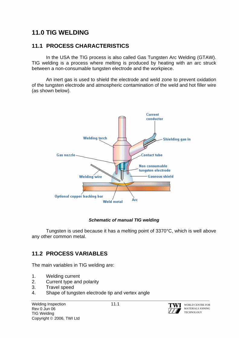
Welding Inspection 11.1 Rev 0 Jun 06 TIG Welding Copyright © 2006, TWI Ltd
WORLD CENTRE FOR MATERIALS JOINING TECHNOLOGY
11.0 TIG WELDING
11.1 PROCESS CHARACTERISTICS In the USA the TIG process is also called Gas Tungsten Arc Welding (GTAW). TIG welding is a process where melting is produced by heating with an arc struck between a non-consumable tungsten electrode and the workpiece. An inert gas is used to shield the electrode and weld zone to prevent oxidation of the tungsten electrode and atmospheric contamination of the weld and hot filler wire (as shown below).
Schematic of manual TIG welding
Tungsten is used because it has a melting point of 3370°C, which is well above any other common metal. 11.2 PROCESS VARIABLES The main variables in TIG welding are: 1. Welding current 2. Current type and polarity 3. Travel speed 4. Shape of tungsten electrode tip and vertex angle

Welding Inspection 11.2 Rev 0 Jun 06 TIG Welding Copyright © 2006, TWI Ltd
WORLD CENTRE FOR MATERIALS JOINING TECHNOLOGY
5. Shielding gas flow rate 6. Electrode extension Each of these variables is considered in more detail in the following sub-sections. 11.2.1 WELDING CURRENT • weld penetration is directly related to welding current • if the welding current is increased but the arc length is kept constant, the arc
voltage will increase. For this reason it is necessary to change the voltage setting when the current is adjusted in order to keep a fixed arc length
• if the welding current is too low, the electrode tip will not be properly heated and an unstable arc may result
• if the welding current is set too high, the electrode tip might overheat and melt, leading to tungsten inclusions
11.2.2 CURRENT TYPE AND POLARITY
• the best welding results are usually obtained with DC electrode negative
• refractory oxides such as those of aluminium or magnesium can hinder fusion but these can be removed by using AC or DC electrode positive
• with a DC positively connected electrode, heat is concentrated at the electrode tip and therefore for DC positive welding the electrode needs to be of greater diameter than when using DC negative if overheating of the tungsten is to be avoided. A water cooled torch is recommended if DC positive is used
• the current carrying capacity of a DC positive electrode is about one tenth that of a negative one and it is therefore limited to welding sections
Ions Electrons Ions ElectronsIons Electrons
DCEN DCEP AC Current
Heat balance 70% at work 30% at electrode
50% at work 50% at electrode
35% at work 65% at electrode
Weld profile Deep, narrow Medium Shallow, wide
Cleaning action
Electrode capacity
No Yes – every half cycle Yes Excellent
(3,2 mm/400A) Good
(3,2 mm/225A) Poor
(6,4 mm/120A)

Welding Inspection 11.3 Rev 0 Jun 06 TIG Welding Copyright © 2006, TWI Ltd
WORLD CENTRE FOR MATERIALS JOINING TECHNOLOGY
11.2.3 TRAVEL SPEED • travel speed affects both weld width and penetration but the effect on width is
more pronounced than that on penetration. • increasing the travel speed reduces the penetration and width • reducing the travel speed increases the penetration and width 11.2.4 TUNGSTEN ELECTRODE TYPES Different types of tungsten electrodes can be used to suit different applications: • pure tungsten electrodes are used when welding light metals with AC because
of their ability to maintain a clean balled end. However they posses poor arc initiation and arc stability in AC mode compared to other types
• thoriated electrodes are alloyed with thorium oxide (thoria) to improve arc initiation. They have higher current carrying capacity than pure tungsten electrodes and maintain a sharp tip for longer. Unfortunately, thoria is slightly radioactive (emitting α radiation) and the dust generated during tip grinding should not be inhaled. Electrode grinding machines used for thoriated tungsten grinding should be fitted with a dust extraction system.
• ceriated & lanthaniated electrodes are alloyed with cerium and lanthanum oxides, for the same reason as thoriated electrodes. They operate successfully with DC or AC but since cerium and lanthanum are not radioactive, these types have been used as replacements for thoriated electrodes
• zirconiated electrodes are alloyed with zirconium oxide. Operating characteristics of these electrodes fall between the thoriated types and pure tungsten. However, since they are able to retain a balled end during welding, they are recommended for AC welding. Also, they have a high resistance to contamination and so they are used for high integrity welds where tungsten inclusions must be avoided.
11.2.5 SHAPE OF TUNGSTEN ELECTRODE TIP • with DC electrode negative, thoriated, ceriated or lanthanated tungsten
electrodes are used with the end is ground to a specific angle (the electrode tip angle or vertex angle – shown below)
• as a general rule, the length of the ground portion of the tip of the electrode should have a length equal to approximately 2 to 2.5 times the electrode diameter
• the tip of the electrode is ground flat to minimise the risk of the tip breaking off when the arc is initiated or during welding (shown below)
• if the vertex angle is increased, the penetration increases • if the vertex angle is decreased, bead width increases • for AC welding, pure or zirconiated tungsten electrodes are used • these are used with a hemispherical (‘balled’) end (as shown below) • in order to produce a ‘balled’ end the electrode is grounded, an arc initiated and
the current increased until it melts the tip of the electrode

Welding Inspection 11.4 Rev 0 Jun 06 TIG Welding Copyright © 2006, TWI Ltd
WORLD CENTRE FOR MATERIALS JOINING TECHNOLOGY
11.2.6 SHIELDING GASES The following inert gases can be used as shielding gases for TIG welding: • argon • helium • mixtures of argon and helium Note: For austenitic stainless steels and some cupro-nickel alloys, argon with up to ~ 5% hydrogen may be used to improve penetration and reduce porosity
Argon Performance item Helium Lower than with helium, which can be helpful when welding thin sections. Less change in arc voltage with variations in arc length.
Arc voltage Higher than with argon. Arc is hotter which is helpful in welding thick sections and viscous metals (e.g. nickel).
Lower than with helium, which gives reduced penetration.
Heating power of the arc
High which can be of advantage when welding metals with high thermal conductivity and thick materials.
Argon is heavier than air, and so requires less gas to shield in the flat and horizontal positions. Also, better draught resistance.
Protection of weld Helium is lighter than air and requires more gas to properly shield the weld. Exception: overhead welding.
Obtained from the atmosphere by the separation of liquefied air – lower cost and greater availability.
Availability and cost Obtained by separation from natural gas – lower availability and higher cost.
Characteristics of argon and helium shielding gases for TIG welding
electrode tip angle (or vertex angle)
electrode tip with flat end electrode tip with a ‘balled’ end
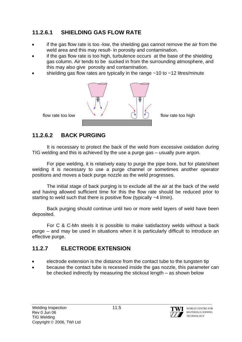
Welding Inspection 11.5 Rev 0 Jun 06 TIG Welding Copyright © 2006, TWI Ltd
WORLD CENTRE FOR MATERIALS JOINING TECHNOLOGY
11.2.6.1 SHIELDING GAS FLOW RATE • if the gas flow rate is too -low, the shielding gas cannot remove the air from the
weld area and this may result- in porosity and contamination. • if the gas flow rate is too high, turbulence occurs at the base of the shielding
gas column. Air tends to be sucked in from the surrounding atmosphere, and this may also give porosity and contamination.
• shielding gas flow rates are typically in the range ~10 to ~12 litres/minute
rate too low
11.2.6.2 BACK PURGING
It is necessary to protect the back of the weld from excessive oxidation during TIG welding and this is achieved by the use a purge gas – usually pure argon.
For pipe welding, it is relatively easy to purge the pipe bore, but for plate/sheet welding it is necessary to use a purge channel or sometimes another operator positions and moves a back purge nozzle as the weld progresses.
The initial stage of back purging is to exclude all the air at the back of the weld and having allowed sufficient time for this the flow rate should be reduced prior to starting to weld such that there is positive flow (typically ~4 l/min).
Back purging should continue until two or more weld layers of weld have been deposited.
For C & C-Mn steels it is possible to make satisfactory welds without a back purge – and may be used in situations when it is particularly difficult to introduce an effective purge. 11.2.7 ELECTRODE EXTENSION • electrode extension is the distance from the contact tube to the tungsten tip • because the contact tube is recessed inside the gas nozzle, this parameter can
be checked indirectly by measuring the stickout length – as shown below
flow rate too low flow rate too high

Welding Inspection 11.6 Rev 0 Jun 06 TIG Welding Copyright © 2006, TWI Ltd
WORLD CENTRE FOR MATERIALS JOINING TECHNOLOGY
• if the electrode extension is too short, the electrode tip will not be adequately
heated leading to an unstable arc • if the electrode extension is set too long, the electrode tip might overheat,
cause melting and lead to tungsten inclusions • as a general rule, stickout length should be 2 to 3 times the electrode diameter 11.3 FILLER WIRES
It is usual practice to use filler wires that have similar composition to the parent metal but they may contain small additions of elements that will combine with any oxygen and nitrogen present. 11.4 TUNGSTEN INCLUSIONS
Small fragments of tungsten that enter a weld will always show up on radiographs (because of the relatively high density of this metal) and for most applications will not be acceptable.
Thermal shock to the tungsten causing small fragments to enter the weld pool is a common cause of tungsten inclusions and is the reason why modern power sources have a current ‘slope-up’ device to minimise this risk.
This device allows the current to rise to the set value over a short period and so the tungsten is heated more slowly and gently.
Stickout Electrode extension
Welding Inspection 11.7 Rev 0 Jun 06 TIG Welding Copyright © 2006, TWI Ltd
WORLD CENTRE FOR MATERIALS JOINING TECHNOLOGY
11.5 CRATER CRACKING
Crater cracking is one form of solidification cracking and some filler metals can be sensitive to it.
Modern power sources have a current ‘slope-out’ device so that at the end of a weld when the welder switches off the current it reduces gradually and the weld pool gets smaller and shallower.
This means that the weld pool has a more favourable shape when it finally solidifies and crater cracking can be avoided. 11.6 COMMON APPLICATIONS OF THE TIG PROCESS
These include autogenous welding of longitudinal seams, in thin walled pipes and tubes, in stainless steel and other alloys, on continuous forming mills .
Using filler wires, TIG is used for making high quality joints in heavier gauge pipe and tubing for the chemical, petroleum and power generating industries.
It is also in the aerospace industry for such items as airframes and rocket motor cases. 11.7 ADVANTAGES OF THE TIG PROCESS • it produces superior quality welds, with very low levels of diffusible hydrogen
and so there is less danger of cold cracking. • it does not give weld spatter nor slag inclusions which makes TIG particularly
suitable for applications that require a high degree of cleanliness (e.g. pipework for the food & drinks industry, semiconductors manufacturing, etc).
• it can be used with or without filler metal and on thin sections without filler, it can produce welds at relatively high speed.
• it enables welding variables to be accurately controlled and is particularly good for controlling weld root penetration in all positions of welding .
• it can be used to weld almost all weldable metals, including dissimilar joints, but is not generally used for those with low melting points such as lead and tin. The method is especially useful in welding the reactive metals with very stable oxides such as aluminium, magnesium, titanium and zirconium.
• the heat source and filler metal additions are controlled independently and thus it is very good for joining thin base metals.

Welding Inspection 11.8 Rev 0 Jun 06 TIG Welding Copyright © 2006, TWI Ltd
WORLD CENTRE FOR MATERIALS JOINING TECHNOLOGY
11.8 DISADVANTAGES OF THE TIG PROCESS • it gives low deposition rates compared with other arc welding processes. • there is need for higher dexterity and welder co-ordination than with MIG/MAG
or MMA welding. • it is less economical than MMA or MIG/MAG for sections thicker than ~10 mm. • it is difficult to fully shield the weld zone in draughty conditions and so may not
be suitable for site/field welding • tungsten inclusions can occur if the electrode is allowed to contact the weld
pool. • the process does not have any cleaning action and so has low tolerance for
contaminants on filler or base metals.

Welding Inspection Rev 0 Jun 06 Copyright © 2006, TWI Ltd
WORLD CENTRE FOR MATERIALS JOINING TECHNOLOGY
Section 12
MIG/MAG Welding

12.0 MIG/MAG WELDING 12.1 THE PROCESS Known in the USA as Gas Metal Arc Welding (GMAW). The MIG/MAG welding process is a versatile technique suitable for both thin sheet and thick section components in most metallic materials. In the process, an arc is struck between the end of a wire electrode and the work piece, melting both to form a weld pool. The wire serves as the source of heat (via the arc at the wire tip) and filler metal for the joint. The wire is fed through a copper contact tube (also called a contact tip) which conducts welding current into the wire. The weld pool is protected from the surrounding atmosphere by a shielding gas fed through a nozzle surrounding the wire. Shielding gas selection depends on the material being welded and the application. The wire is fed from a reel by a motor drive, and the welder or machine moves the welding gun or torch along the joint line. The process offers high productivity and is economical because the consumable wire is continuously fed. A schematic diagram of the process is shown in Fig.1.
The MIG/MAG process uses semiautomatic, mechanised, or automatic equipment. In semiautomatic welding, the wire feed rate and arc length are controlled automatically, but the travel speed and wire position are under manual control. In mechanised welding, all parameters are under automatic control, but they can be varied manually during welding, e.g. steering of the welding head and adjustment of wire feed speed and arc voltage. With automatic equipment, there is no manual intervention during welding. Fig 1.1 shows equipment required for the MIG/MAG process.
Fig 1 Schematic of MIG/MAG Welding
Welding Inspection 12.1 Rev 0 Jun 06 MIG/MAG Welding Copyright © 2006, TWI Ltd
WORLD CENTRE FOR MATERIALS JOINING TECHNOLOGY
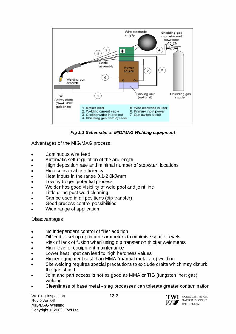
Fig 1.1 Schematic of MIG/MAG Welding equipment Advantages of the MIG/MAG process: • Continuous wire feed • Automatic self-regulation of the arc length • High deposition rate and minimal number of stop/start locations • High consumable efficiency • Heat inputs in the range 0.1-2.0kJ/mm • Low hydrogen potential process • Welder has good visibility of weld pool and joint line • Little or no post weld cleaning • Can be used in all positions (dip transfer) • Good process control possibilities • Wide range of application
Disadvantages • No independent control of filler addition • Difficult to set up optimum parameters to minimise spatter levels • Risk of lack of fusion when using dip transfer on thicker weldments • High level of equipment maintenance • Lower heat input can lead to high hardness values • Higher equipment cost than MMA (manual metal arc) welding • Site welding requires special precautions to exclude drafts which may disturb
the gas shield • Joint and part access is not as good as MMA or TIG (tungsten inert gas)
welding • Cleanliness of base metal - slag processes can tolerate greater contamination
Welding Inspection 12.2 Rev 0 Jun 06 MIG/MAG Welding Copyright © 2006, TWI Ltd
WORLD CENTRE FOR MATERIALS JOINING TECHNOLOGY

12.2 PROCESS VARIABLES The primary variables in MIG/MAG welding are: • Welding current/wire feed speed • Voltage • Gases • Travel speed and electrode orientation • Inductance • Contact tip to work distance • Nozzle to work distance • Shielding gas nozzle • Type of metal transfer 12.2.1 WIRE FEED SPEED
Increasing the wire feed speed automatically increases the current in the wire. Wires are generally produced in 0.6, 0.8, 1.0, 1.2, 1.4 & 1.6 mm diameter. 12.2.2 VOLTAGE
The voltage setting is the most important setting in spray transfer as it controls the arc length. In dip transfer it also effects the rise of current and the overall heat input into the weld. An increase of both Wire Feed Speed/current and voltage will increase heat input. The welding connections need to be checked for soundness, as any loose connections will result in resistance and will cause the voltage to drop in the circuit and will affect the characteristic of the welding arc. The voltage will affect the type of transfer achievable, but this is also highly dependent on the type of gas being used.
Welding Inspection 12.3 Rev 0 Jun 06 MIG/MAG Welding Copyright © 2006, TWI Ltd
WORLD CENTRE FOR MATERIALS JOINING TECHNOLOGY
• Increasing arc voltage • Reduced penetration, increased width
• Excessive voltage can cause porosity, spatter and undercut
Fig 2 The effect of arc voltage
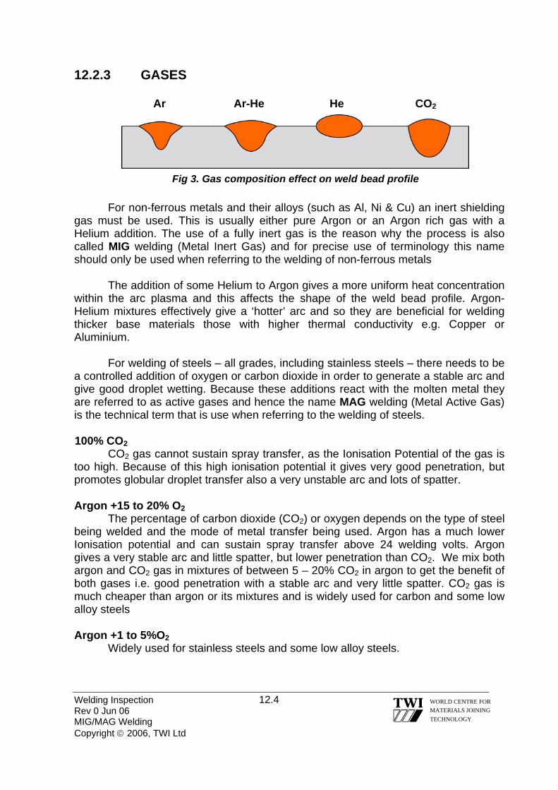
12.2.3 GASES Ar A
Welding Inspection 12.4 Rev 0 Jun 06 MIG/MAG Welding Copyright © 2006, TWI Ltd
WORLD CENTRE FOR MATERIALS JOINING TECHNOLOGY
r-He He CO2
Fig 3. Gas composition effect on weld bead profile
For non-ferrous metals and their alloys (such as Al, Ni & Cu) an inert shielding gas must be used. This is usually either pure Argon or an Argon rich gas with a Helium addition. The use of a fully inert gas is the reason why the process is also called MIG welding (Metal Inert Gas) and for precise use of terminology this name should only be used when referring to the welding of non-ferrous metals
The addition of some Helium to Argon gives a more uniform heat concentration within the arc plasma and this affects the shape of the weld bead profile. Argon-Helium mixtures effectively give a ‘hotter’ arc and so they are beneficial for welding thicker base materials those with higher thermal conductivity e.g. Copper or Aluminium.
For welding of steels – all grades, including stainless steels – there needs to be a controlled addition of oxygen or carbon dioxide in order to generate a stable arc and give good droplet wetting. Because these additions react with the molten metal they are referred to as active gases and hence the name MAG welding (Metal Active Gas) is the technical term that is use when referring to the welding of steels. 100% CO2
CO2 gas cannot sustain spray transfer, as the Ionisation Potential of the gas is too high. Because of this high ionisation potential it gives very good penetration, but promotes globular droplet transfer also a very unstable arc and lots of spatter. Argon +15 to 20% O2
The percentage of carbon dioxide (CO2) or oxygen depends on the type of steel being welded and the mode of metal transfer being used. Argon has a much lower Ionisation potential and can sustain spray transfer above 24 welding volts. Argon gives a very stable arc and little spatter, but lower penetration than CO2. We mix both argon and CO2 gas in mixtures of between 5 – 20% CO2 in argon to get the benefit of both gases i.e. good penetration with a stable arc and very little spatter. CO2 gas is much cheaper than argon or its mixtures and is widely used for carbon and some low alloy steels
Argon +1 to 5%O2
Widely used for stainless steels and some low alloy steels.

Figure 4 Active shielding gas mixtures for MAG welding of carbon, carbon-manganese
and low alloy steels (Blue is a cooler gas mixture; red is a hotter mixture).
Gas mixtures - Helium in place of argon gives a hotter arc, more fluid weld pool
and better weld profile. These quaternary mixtures permit higher welding speeds, but may not be suitable for thin sections. Stainless steels
Austenitic stainless steels are typically welded with argon-CO2 /O2 mixtures for spray transfer, or argon-helium-CO2 mixtures for all modes of transfer. The oxidising potential of the mixtures are kept to a minimum (2-2.5% maximum CO2 content) in order to stabilise the arc, but with the minimum effect on corrosion performance. Because austenitic steels have a high thermal conductivity, the addition of helium helps to avoid lack of fusion defects and overcome the high heat dissipation into the material. Helium additions are up to 85%, compared with ~25% for mixtures used for carbon and low alloy steels. CO2 -containing mixtures are sometimes avoided to eliminate potential carbon pick-up.
Figure 5 Active shielding gas mixtures for MAG welding of stainless steels
(Blue is a cooler gas mixture; red is a hotter mixture)
Welding Inspection 12.5
Rev 0 Jun 06 MIG/MAG Welding Copyright © 2006, TWI Ltd
WORLD CENTRE FOR MATERIALS JOINING TECHNOLOGY

For martensitic and duplex stainless steels, specialist advice should be sought. Some Ar-He mixtures containing up to 2.5%N2 are available for welding duplex stainless steels. Light alloys, e.g. Aluminium and magnesium, and copper and nickel and their alloys
Inert gases are used for light alloys and alloys that are sensitive to oxidation. Welding grade inert gases should be purchased rather than commercial purity to ensure good weld quality. Argon
Argon can be used for aluminium because there is sufficient surface oxide available to stabilise the arc. For materials that are sensitive to oxygen, such as titanium and nickel alloys, arc stability may be difficult to achieve with inert gases in some applications. The density of argon is approximately 1.4 times that of air. Therefore, in the downhand position, the relatively heavy argon is very effective at displacing air. A disadvantage is that when working in confined spaces, there is a risk of argon building up to dangerous levels and asphyxiating the welder. Argon-helium mixtures
Argon is most commonly used for MIG welding of light alloys, but some advantage can be gained by the use of helium and argon/helium mixtures. Helium possesses a higher thermal conductivity than argon. The hotter weld pool produces improved penetration and/or an increase in welding speed. High helium contents give a deep broad penetration profile, but produce high spatter levels. With less than 80% argon, a true spray transfer is not possible. With globular-type transfer, the welder should use a 'buried' arc to minimise spatter. Arc stability can be problematic in helium and argon-helium mixtures, since helium raises the arc voltage, and therefore there is a larger change in arc voltage with respect to arc length. Helium mixtures require higher flow rates than argon shielding in order to provide the same gas protection.
There is a reduced risk of lack of fusion defects when using argon-helium mixtures, particularly on thick section aluminium. Ar-He gas mixtures will offset the high heat dissipation in material over about 3mm thickness.
Figure 6 Inert shielding gas mixtures for MIG welding of aluminium, magnesium,
titanium, nickel and copper alloys (Blue is a cooler gas mixture; red is a hotter mixture)
Welding Inspection 12.6 Rev 0 Jun 06 MIG/MAG Welding Copyright © 2006, TWI Ltd
WORLD CENTRE FOR MATERIALS JOINING TECHNOLOGY

Welding Inspection 12.7 Rev 0 Jun 06 MIG/MAG Welding Copyright © 2006, TWI Ltd
WORLD CENTRE FOR MATERIALS JOINING TECHNOLOGY
A summary table of shielding gases and mixtures used for different base materials is given in Table 1.
Metal Shielding gas Reaction behaviour Characteristics
Carbon steel
Argon- CO2 Slightly oxidising
Increasing CO2 content gives hotter arc, improved arc stability, deeper penetration, transition from 'finger'-type to bowl-shaped penetration profile, more fluid weld pool giving flatter weld bead with good wetting, increased spatter levels, better toughness than CO2. Min 80% Argon for axial spray transfer. General-purpose mixture: Argon-10-15% CO2.
Argon- O2 Slightly oxidising
Stiffer arc than Ar- CO2 mixtures, minimises undercutting, suited to spray transfer mode, lower penetration than Ar- CO2 mixtures, 'finger'-type weld bead penetration at high current levels. General-purpose mixture: Argon-3% CO2.
Ar-He-CO2 Slightly oxidising
Substitution of helium for argon gives hotter arc, higher arc voltage, more fluid weld pool, flatter bead profile, more bowl-shaped and deeper penetration profile and higher welding speeds, compared with Ar- CO2 mixtures. High cost.
CO2 Oxidising Arc voltages 2-3V higher than Ar- CO2 mixtures, best penetration, higher welding speeds, dip transfer or buried arc technique only, narrow working range, high spatter levels, low cost.
Stainless steels
He-Ar- CO2 Slightly oxidising
Good arc stability with minimum effect on corrosion resistance (carbon pickup), higher helium contents designed for dip transfer, lower helium contents designed for pulse and spray transfer. General-purpose gas: He-Ar -2% CO2.
Argon- O2 Slightly oxidising
Spray transfer only, minimises undercutting on heavier sections, good bead profile.
Aluminium, copper, nickel, titanium alloys
Argon Inert Good arc stability, low spatter, and general-purpose gas. Titanium alloys require inert gas backing and trailing shields to prevent air contamination.
Argon-helium Inert Higher heat input offsets high heat dissipation on thick sections, lower risk of lack of fusion defects, higher spatter, higher cost than Argon.
Table 1 Shielding gas mixtures for MIG/MAG welding - summary

12.2.4 TRAVEL SPEED AND ELECTRODE ORIENTATION
The faster the travel speed the less penetration, narrower bead width and the higher risk of undercut
• Increasing travel speed • Reduced penetration and width,
undercut
Figure 7 The effect of travel speed
Penetration Deep Moderate Shallow Excess weld metal Maximum Moderate Minimum Undercut Severe Moderate M inimum
Figure 8 The effect of torch angle
12.2.5 EFFECT OF CONTACT TIP TO WORK PIECE DISTANCE (CTWD)
The CTWD has an influence over the welding current because of resistive heating in the electrode extension (see Fig 9). The welding current required to melt the electrode at the required rate (to match the wire feed speed) reduces as the CTWD is increased. Long electrode extensions can cause lack of penetration, for example, in narrow gap joints, or with poor manipulation of the welding gun. Conversely, the welding current increases when the CTWD is reduced. This provides the experienced welder with a means of controlling the current during welding, but can result in variable penetration in manual welding with a constant voltage power source.
As the electrode extension is increased, the burn-off rate increases for a given welding current due to increased resistive heating. Increasing the electrode extension,
Welding Inspection 12.8 Rev 0 Jun 06 MIG/MAG Welding Copyright © 2006, TWI Ltd
WORLD CENTRE FOR MATERIALS JOINING TECHNOLOGY

e.g. in mechanised applications, is therefore one method of increasing deposition rates, as the wire feed speed is increased to maintain the required welding current.
Resistive heating depends on the resistivity of the electrode, the length of the electrode extension and the wire diameter. The effect is therefore more pronounced for welding materials which have high resistivity, such as steels. The electrode extension should be kept small when small diameter wires are being used to prevent excessive heating in the wire and avoid the resulting poor bead shape.
Welding Inspection 12.9 Rev 0 Jun 06 MIG/MAG Welding Copyright © 2006, TWI Ltd
WORLD CENTRE FOR MATERIALS JOINING TECHNOLOGY
Contact tip
Gas nozzle
Electrode extension Contact tip-
to-work distance
Arc length Workpiece Fig 9 Contact tip to work piece distance; electrode extension; and nozzle to work piece
distance
Contact tip setback
Nozzle-to-work (stand-off) distance
Arc length L’ = 12,7 mm Arc voltage = Increases Welding current = Drops
Sudden change in gun position Stable condition
19 mm
Arc length L = 6,4 mm Arc voltage = 24V Welding current = 250A
L
25 mm L’
Fig 10 The effect of increasing the Contact tip to work piece distance

Welding Inspection 12.10 Rev 0 Jun 06 MIG/MAG Welding Copyright © 2006, TWI Ltd
WORLD CENTRE FOR MATERIALS JOINING TECHNOLOGY
Increased extension
Fig 11 The effect of increasing electrode extension
At short CTWDs, radiated heat from the weld pool can cause overheating of the contact tube and welding torch. This can lead to spatter adherence and increased wear of the contact tube.
The electrode extension should be checked when setting up welding conditions
or when fitting a new contact tube. Normally measured from the contact tube to the work piece (Fig. 12), suggested CTWDs for the principal metal transfer modes are:
Metal transfer mode Contact tube to work piece distance (CTWD)
(mm) Dip 10-15 Spray 20-25 Pulse 15-20
Set up for Spray transfer Set up for Dip transfer
Fig 12 Suggested contact tip to work distance
Electrode extension 19-25 mm
Contact tip recessed (3-5 mm)
Contact tip extension (0-3,2 mm)
Electrode extension 6-13 mm

12.2.6 EFFECT OF NOZZLE TO WORK DISTANCE
Nozzle to work distance (See Fig 12) has a considerable effect on gas shielding efficiency; a decrease having the effect of stiffening the column. The nozzle to work distance is typically 12-15mm. If the CTWD is simultaneously reduced, however, the deposition rate at a given current is decreased and visibility and accessibility are affected; so, in practice, a compromise is necessary. The following gives suggested settings for the mode of metal transfer being used
Metal transfer mode Contact tip position relative to nozzle Dip 2mm inside to 2mm protruding Spray 4-8mm inside Spray (aluminium) 6-10mm inside
12.2.7 SHIELDING GAS NOZZLE
The purpose of the shielding gas nozzle is to produce a laminar gas flow in order to protect the weld pool from atmospheric contamination. Nozzle sizes range from 13mm to 22mm diameter. The nozzle diameter should be increased in relation to the size of the weld pool. Therefore, larger diameter nozzles are used for high current, spray transfer applications, and smaller diameter nozzles for dip transfer. The flow rate must also be tuned to the nozzle diameter and shielding gas type to give sufficient weld pool coverage. Gas nozzles for dip transfer welding tend to be tapered at the outlet of the nozzle
Joint access and joint type should also be considered when selecting the required gas nozzle and flow rate. Use of too small a nozzle may cause it to become obstructed by spatter more quickly and, if the wire bends on leaving the contact tube the shielding envelope and arc location may not coincide. 12.2.8 TYPES OF METAL TRANSFER
Fig 13. Arc characteristic curve, schematic
Welding Inspection 12.11 Rev 0 Jun 06 MIG/MAG Welding Copyright © 2006, TWI Ltd
WORLD CENTRE FOR MATERIALS JOINING TECHNOLOGY

1) Dip Transfer: Key characteristics: • Metal transfer by wire 'dipping' or short circuiting into the weld pool • Relatively low heat input process • Low weld pool fluidity • Used for thin sheet metal above 0.8mm and typically less than 3.2mm, positional welding of thicker section and root runs in open butt joints • Process stability and spatter can be a problem if poorly tuned • Lack of fusion risk if poorly set up and applied • Not used for non-ferrous metals and alloys In dip transfer the wire short-circuits the arc between 50 – 200 times/second. This type of transfer is normally achieved with C02 or mixtures of C02 & argon gas + low amps & welding volts < 24 volts.
Fig 14. Dip transfer
2) Spray Transfer: Key characteristics: • free-flight metal transfer • high heat input • high deposition rate • smooth, stable arc • used on steels above 6mm thick and aluminium alloys above 3mm thick
Spray transfer occurs at high currents and high voltages. Above the transition current, metal transfer is in the form of a fine spray of small droplets, which are projected across the arc with low spatter levels. The high welding current produces strong electromagnetic forces (known as the 'pinch effect') that cause the molten filament supporting the droplet to neck down. The droplets detach from the tip of the wire and accelerate across the arc gap. The frequency at which the droplets detach increases with increasing current. The droplet size equates to the wire diameter at the threshold level but decreases significantly as the welding current increases. At very high currents (wire feed speeds), the molten droplets can start to rotate (rotating transfer). The arc current is flowing for the entire period of the drop detachment, resulting in maximum penetration and a high heat input. When the correct arc voltage to give spray transfer is used, the arc is short with the wire tip 1-3mm from the surface of the plate.
Welding Inspection 12.12 Rev 0 Jun 06 MIG/MAG Welding Copyright © 2006, TWI Ltd
WORLD CENTRE FOR MATERIALS JOINING TECHNOLOGY

With steels it can be used only in down-hand butts and H/V fillet welds, but gives higher deposition rate, penetration and fusion than dip transfer because of the continuous arc heating. It is mainly used for steel plate thicknesses > 3mm but has limited use for positional welding due to the potential large weld pool involved.
Fig 15 Spray transfer
3) Pulsed Transfer: Key characteristics: • free-flight droplet transfer without short-circuiting over the entire working range • very low spatter • lower heat input than spray transfer • reduced risk of lack of fusion compared with dip transfer • control of weld bead profile for dynamically loaded parts • process control/flexibility • enables use of larger diameter, less expensive wires with thinner plates - more
easily fed (a particular advantage for aluminium welding)
Pulsing the welding current extends the range of spray transfer operation well below the natural transition from dip to spray transfer. This allows smooth, spatter-free spray transfer to be obtained at mean currents below the transition level, e.g. 50-150A and at lower heat inputs. Pulsing was introduced originally for control of metal transfer by imposing artificial cyclic operation on the arc system by applying alternately high and low currents.
A typical pulse waveform and the main pulse welding variables are shown in Fig 16. A low background current (typically 20-80A) is supplied to maintain the arc, keep the wire tip molten, give stable anode and cathode roots and maintain average current during the cycle. Droplet detachment occurs during a high current pulse at current levels above the transition current level. The pulse of current generates very high electromagnetic forces, which cause a strong pinch effect on the metal filament supporting the droplet; the droplet is detached and is projected across the arc gap. Pulse current and current density must be sufficiently high to ensure that spray transfer (not globular) always occurs so that positional welding can be used. Welding Inspection 12.13 Rev 0 Jun 06 MIG/MAG Welding Copyright © 2006, TWI Ltd
WORLD CENTRE FOR MATERIALS JOINING TECHNOLOGY

Pulse transfer uses pulses of current to fire a single globule of metal across the arc gap at a frequency between 50–300 Pulses/second. Pulse transfer is a development of spray transfer, that gives positional welding capability for steels, combined with controlled heat input, good fusion, and high productivity. It may be used for all sheet steel thickness > 1mm, but is mainly used for positional welding of steels > 6mm.
Fig 16. Pulsed welding waveform and parameters 4) Globular Transfer: Key characteristics: • irregular metal transfer • medium heat input • medium deposition rate • risk of spatter • not widely used in the UK; can be used for mechanised welding of medium
thickness steels (typically 3-6mm) in the flat (PA) position
The globular transfer range occupies the transitional range of arc voltage between free flight and fully short-circuiting transfer. Irregular droplet transfer and arc instability are inherent, particularly when operating near the transition threshold. In globular transfer, a molten droplet of several times the electrode diameter forms on the wire tip. Gravity eventually detaches the globule when its weight overcomes surface tension forces, and transfer takes place often with excessive spatter. Before transfer occurs, the arc wanders and its cone covers a large area, dissipating energy. There is a short duration short circuit when the droplet contacts with the molten pool, but rather than causing droplet transfer, it occurs as a result of it. Although the short circuit is of very short duration, some inductance is necessary to reduce spatter, although to the operator the short circuits are not discernible and the arc has the appearance of a free flight type.
To further minimise spatter levels, it is common to operate with a very short arc length, and in some cases a buried arc technique is adopted. Globular transfer can
Welding Inspection 12.14 Rev 0 Jun 06 MIG/MAG Welding Copyright © 2006, TWI Ltd
WORLD CENTRE FOR MATERIALS JOINING TECHNOLOGY
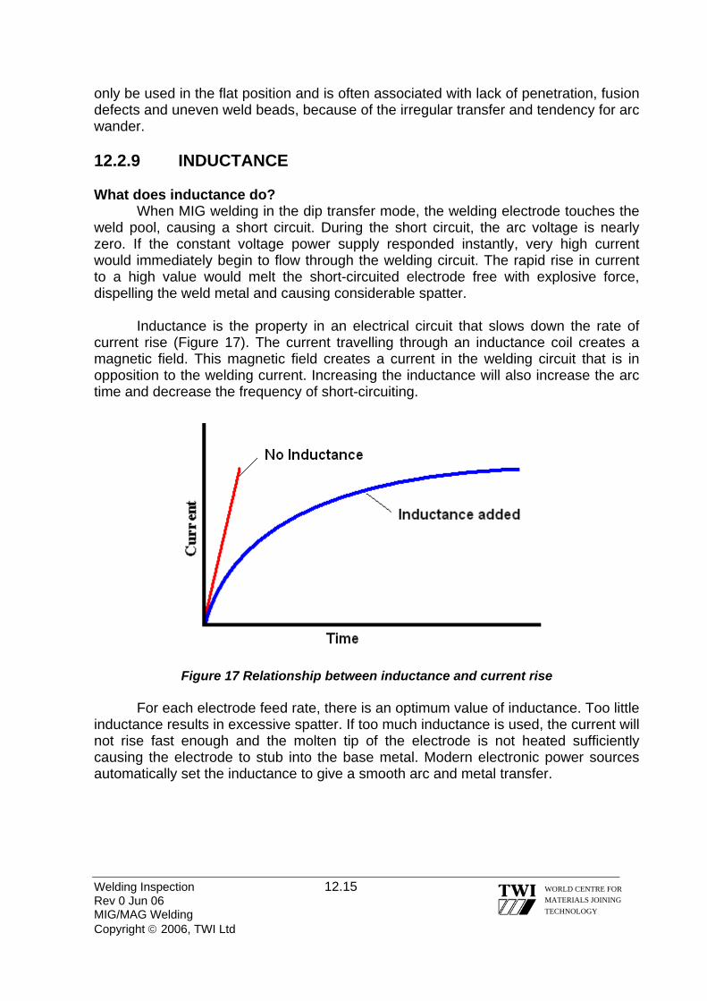
only be used in the flat position and is often associated with lack of penetration, fusion defects and uneven weld beads, because of the irregular transfer and tendency for arc wander.
12.2.9 INDUCTANCE What does inductance do?
When MIG welding in the dip transfer mode, the welding electrode touches the weld pool, causing a short circuit. During the short circuit, the arc voltage is nearly zero. If the constant voltage power supply responded instantly, very high current would immediately begin to flow through the welding circuit. The rapid rise in current to a high value would melt the short-circuited electrode free with explosive force, dispelling the weld metal and causing considerable spatter.
Inductance is the property in an electrical circuit that slows down the rate of current rise (Figure 17). The current travelling through an inductance coil creates a magnetic field. This magnetic field creates a current in the welding circuit that is in opposition to the welding current. Increasing the inductance will also increase the arc time and decrease the frequency of short-circuiting.
Figure 17 Relationship between inductance and current rise
For each electrode feed rate, there is an optimum value of inductance. Too little inductance results in excessive spatter. If too much inductance is used, the current will not rise fast enough and the molten tip of the electrode is not heated sufficiently causing the electrode to stub into the base metal. Modern electronic power sources automatically set the inductance to give a smooth arc and metal transfer.
Welding Inspection 12.15 Rev 0 Jun 06 MIG/MAG Welding Copyright © 2006, TWI Ltd
WORLD CENTRE FOR MATERIALS JOINING TECHNOLOGY

12.3 ARC CHARACTERISTIC FOR MIG & MAG:
In MIG/MAG welding we require different welding equipment than used for MMA & TIG, as the arc length is controlled by voltage. Welding circuit
In MIG/MAG welding, an arc is established between the wire electrode and the work piece. To do this properly, the arc requires a smooth flow of electricity through the complete electrical circuit, with minimum resistance. This requires a stable power source with appropriate static and dynamic characteristics and good electrical contact at the contact tube. Consideration must also be given to other electrical connections in the circuit, such as those on the welding power cable and the current return clamp. These can increase circuit resistance or cause resistance to vary. Damaged cables or connectors should be replaced.
The return clamp should be attached to clean bare metal. Welders often make the mistake of attaching the work clamp to a painted panel or a rusty surface. Both of these surfaces are electrical insulators and do not allow the welding current to flow properly. The resulting welding arc will be difficult to establish and not very stable. Other signs of an improper electrical connection are a work clamp that is hot to the touch or cables that generate heat.
Another key point to consider when attaching the welding return clamp is to place it on the piece being welded. Welding current will seek the path of least resistance; so; if care is not taken to place the welding return close to the arc, the welding current may find a path unknown to the operator and destroy components unintended to be in the welding circuit, e.g. manipulators. The location of the return clamp can influence the likelihood of arc blow.
Additional earth leads may also be required to protect the operator from electric shock. To achieve this we require a Constant Voltage (Flat) characteristic power source, see fig 18.
Welding Inspection 12.16 Rev 0 Jun 06 MIG/MAG Welding Copyright © 2006, TWI Ltd
WORLD CENTRE FOR MATERIALS JOINING TECHNOLOGY
Figure 18 Constant Voltage (Flat) Characteristic
Current
Voltage (V)
Welding Inspection 12.17 Rev 0 Jun 06 MIG/MAG Welding Copyright © 2006, TWI Ltd
WORLD CENTRE FOR MATERIALS JOINING TECHNOLOGY
The slope of a 'flat' output characteristic is typically 2-6V per 100A. This means that any change in arc length (voltage) brings about a large change in welding current. This characteristic produces an arc that remains stable as it responds rapidly to any changes in arc length or electrode extension (due to movement of the work piece or torch, lack of smoothness of feeding the wire in the gun or erratic current pick-up at the contact tube). This is often referred to as a self-adjusting arc, as the power source is controlling the arc length, not the operator. There is some inherent self-adjustment due to resistive heating in the electrical stickout, but a CV power source design helps to give a more rapid response. The flat characteristic also provides a rapid surge of current when the wire first short-circuits with the work at the start of a weld, so it gives excellent arc starting performance. Many power sources allow adjustment of the slope of the characteristic to control the peak short circuit current; some have a fixed slope and are designed for a particular condition of welding.
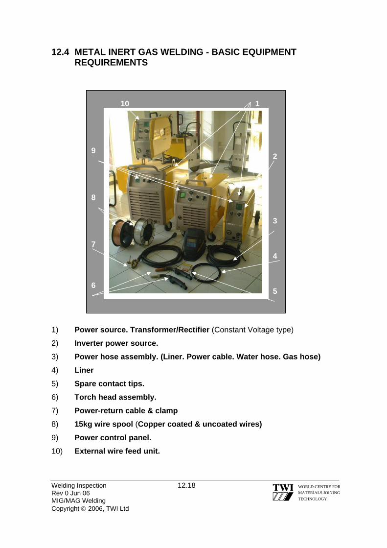
12.4 METAL INERT GAS WELDING - BASIC EQUIPMENT REQUIREMENTS
Welding Inspection 12.18 Rev 0 Jun 06 MIG/MAG Welding Copyright © 2006, TWI Ltd
WORLD CENTRE FOR MATERIALS JOINING TECHNOLOGY
1 10
5
4
3
9 2
6
7
8
1) Power source. Transformer/Rectifier (Constant Voltage type)
2) Inverter power source. 3) Power hose assembly. (Liner. Power cable. Water hose. Gas hose) 4) Liner 5) Spare contact tips. 6) Torch head assembly. 7) Power-return cable & clamp 8) 15kg wire spool (Copper coated & uncoated wires) 9) Power control panel. 10) External wire feed unit.
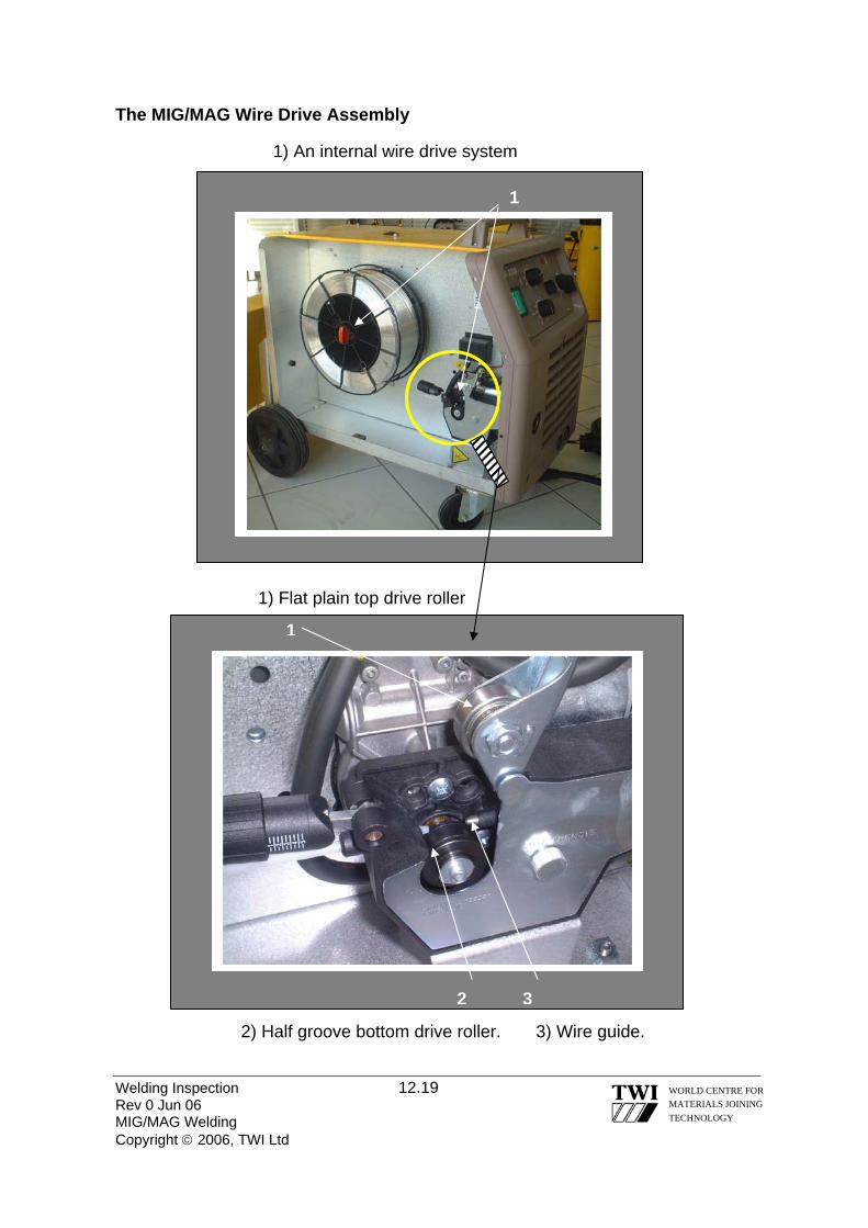
The MIG/MAG Wire Drive Assembly
Welding Inspection 12.19 Rev 0 Jun 06 MIG/MAG Welding Copyright © 2006, TWI Ltd
WORLD CENTRE FOR MATERIALS JOINING TECHNOLOGY
1
1
32
1) An internal wire drive system
1) Flat plain top drive roller
2) Half groove bottom drive roller. 3) Wire guide.
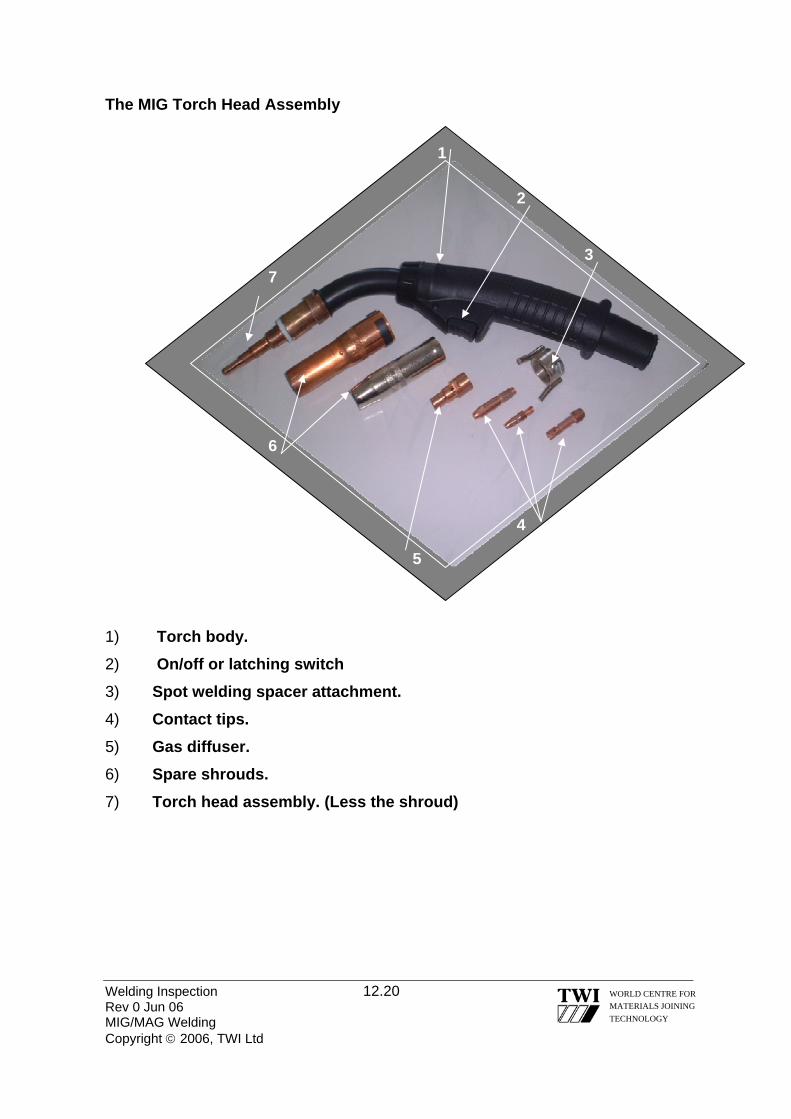
The MIG Torch Head Assembly
Welding Inspection 12.20 Rev 0 Jun 06 MIG/MAG Welding Copyright © 2006, TWI Ltd
WORLD CENTRE FOR MATERIALS JOINING TECHNOLOGY
7
2
6
5
4
3
1
1) Torch body. 2) On/off or latching switch 3) Spot welding spacer attachment. 4) Contact tips. 5) Gas diffuser. 6) Spare shrouds. 7) Torch head assembly. (Less the shroud)

12.5 IMPORTANT INSPECTION POINTS/CHECKS WHEN MIG/MAG WELDING 1) The Welding Equipment: A visual check should be made to ensure the welding equipment is in good condition.
2) The Electrode Wire The diameter, specification and the quality of the wire are the main inspection headings. The level of de-oxidation of the wire is an important factor with Single, Double & Triple de-oxidised wires being available. The higher the level of de-oxidants in the wire, then the lower is the chance of occurrence of porosity in the weld. The quality of the wire winding, copper coating, and temper are also important factors in minimising wire feed problems. Quality of wire windings and increasing costs (a) Random wound. (b) Layer wound. (c) Precision layer wound.
3) The Drive Rolls and Liner. Check the drive rolls are of the correct size for the wire and that the pressure is only hand tight, or just sufficient to drive the wire. Any excess pressure will deform the wire to an ovular shape. This will make the wire very difficult to drive through the liner and result in arcing in the contact tip and excessive wear of the contact tip and liner. Check that the liner is the correct type and size for the wire. A size of liner will generally fit 2 sizes of wire i.e. (0.6 & 0.8) (1.0 & 1.2) (1.4 & 1.6) mm diameter. Steel liners are used for steel wires and Teflon liners for aluminium wires. 4) The Contact Tip. Check that the contact tip is the correct size for the wire being driven, and check the amount of wear frequently. Any loss of contact between the wire and contact tip will reduce the efficiency of current pick. Most steel wires are copper coated to maximise the transfer of current by contact between 2 copper surfaces at the contact tip, this also inhibits corrosion. The contact tip should be replaced regularly. 5) The Connections. The length of the electric arc in MIG/MAG welding is controlled by the voltage settings. This is achieved by using a constant voltage volt/amp characteristic inside the equipment. Any poor connection in the welding circuit will affect the nature and stability of the electric arc, and is thus is a major inspection point. 6) Gas & Gas Flow Rate. The type of gas used is extremely important to MIG/MAG welding, as is the flow rate from the cylinder, which must be adequate to give good coverage over the solidifying and molten metal to avoid oxidation and porosity.
Welding Inspection 12.21 Rev 0 Jun 06 MIG/MAG Welding Copyright © 2006, TWI Ltd
WORLD CENTRE FOR MATERIALS JOINING TECHNOLOGY

Welding Inspection 12.22 Rev 0 Jun 06 MIG/MAG Welding Copyright © 2006, TWI Ltd
WORLD CENTRE FOR MATERIALS JOINING TECHNOLOGY
7) Other Variable Welding Parameters. Checks should be made for correct WIRE FEED SPEED, Voltage, Speed of travel, and all other essential variables of the process given on the approved welding procedure. 8) Safety Checks: Checks should be made on the current carrying capacity, or duty cycle of equipment and electrical insulation. Correct extraction systems should be in use to avoid exposure to ozone and fumes. A check should always be made to ensure that the welder is qualified to weld the procedure being employed. Typical Welding Imperfections: 1) Silica inclusions, (on ferritic steels only) caused by poor inter-run cleaning. 2) Lack of sidewall fusion during dip transfer welding thick section vertically down. 3) Porosity caused from loss of gas shield and low tolerance to contaminants 4) Burn through from using the incorrect metal transfer mode on sheet metal. 12.6 ADVANTAGES OF FLUX CORED ARC WELDING In the mid 80’s the development of self-shielded and dual-shielded FCAW was a major step in the successful application of on-site semi automatic welding, and has also enabled a much wider range of materials to be welded. The wire consists of a metal sheath containing a granular flux. This flux can contain elements that would normally be used in MMA electrodes and so the process has a very wide range of applications. In addition we can also add gas producing elements and compounds to the flux and so the process can become independent of a separate gas shield, which restricted the use of conventional MIG/MAG welding in many field applications. “Dual Shield” wires obtain their gas shielding from a combination of flux and separate shielding gas. Most wires are sealed mechanically and hermetically with various forms of joint. The effectiveness of the joint of the wire is an inspection point of cored wire welding, particularly with wires containing basic fluxes, as moisture can easily be absorbed into a damaged or poor seam. It is the accepted practise when using basic wires that the first few meters of wire from the reel is stripped off and discarded as moisture can be absorbed up the length of the wire through the core of flux if incorrectly stored. Baking of cored wires is ineffective and will do nothing to restore the condition of a contaminated flux within a wire.

Welding Inspection 12.23 Rev 0 Jun 06 MIG/MAG Welding Copyright © 2006, TWI Ltd
WORLD CENTRE FOR MATERIALS JOINING TECHNOLOGY
A major advantage of fluxed cored wires is that they produce extremely good penetration. This is caused by the amount of current density in the wire, or in other words the amount of current carried in the available CSA of the conductor. 12.7 SUMMARY OF SOLID WIRE MIG/MAG GMAW Equipment requirements: • A Transformer/Rectifier. (Constant voltage type) • A power and power return cable. • An Inert, active, or mixed shielding gas. (Argon or CO2) • Gas hose, flow meter, & gas regulator. • MIG torch with hose, liner, diffuser, contact tip & nozzle. • Wire feed unit with correct drive rolls. • Electrode wire to correct specification and diameter. • Correct visor/glass, all safety clothing and good extraction. Parameters & Inspection Points: • Wire Feed Speed/Amperage • Open Circuit &Welding voltage. • Wire type & diameter. • Gas type & flow rate. • Contact tip size and condition. • Roller type, size and pressure. • Liner size. • Inductance settings. • Insulation/extraction. • Connections. (Voltage drops) • Duty cycles. • Travel speed, direction & angles. Typical Welding Imperfections: Silica inclusions. Lack of fusion. (Dip transfer) Surface Porosity. Advantages & Disadvantages: Advantages: Disadvantages: High productivity Lack of fusion. (Dip Transfer) Easily automated. Small range of consumables. All positional (Dip & Pulse) Protection for site working. Material thickness range Complex equipment Continuous electrode High ozone levels

Welding Inspection Rev 0 Jun 06 Copyright © 2006, TWI Ltd
WORLD CENTRE FOR MATERIALS JOINING TECHNOLOGY
Section 13
Submerged Arc Welding

13.0 SUBMERGED ARC WELDING 13.1 THE PROCESS Abbreviated as SAW, this is a welding process where an arc is struck between a continuous bare wire and the parent plate. The arc, electrode end and the molten pool are submerged in an agglomerated or fused powdered flux, which turns, into a slag in its lower layers when subjected to the heat of the arc, thus protecting the weld from contamination. The wire electrode is fed continuously by a feed unit of motor-driven rollers, which usually are voltage-controlled to ensure an arc of constant length. The flux is fed from a hopper fixed to the welding head, and a tube from the hopper spreads the flux in a continuous elongated mound in front of the arc along the line of the intended weld and of sufficient depth to submerge the arc completely so that there is no spatter, the weld is shielded from the atmosphere, and there are no ultra-violet or infra-red radiation effects (see figure below). Unmelted flux is reclaimed for use. The use of powdered flux restricts the process to the flat and horizontal-vertical welding positions.
Submerged arc welding is noted for its ability to employ high weld currents
owing to the properties and functions of the flux. Such currents give deep penetration and high dilution where twice as much parent metal as wire electrode is melted. Generally a DC electrode positive polarity is employed up to about 1000 amps because it produces a deep penetration. On some applications (i.e. cladding operations) DC electrode negative is used due to the shallower penetration and reduced dilution. At higher currents or in case of multiple electrode systems, AC is often preferred to avoid the problem of arc blow (when used with multiple electrode systems, DC electrode positive is used for the lead arc and AC is used for the trail arc).
Welding Inspection 13.1 Rev 0 Jun 06 Submerged Arc Welding Copyright © 2006, TWI Ltd
WORLD CENTRE FOR MATERIALS JOINING TECHNOLOGY
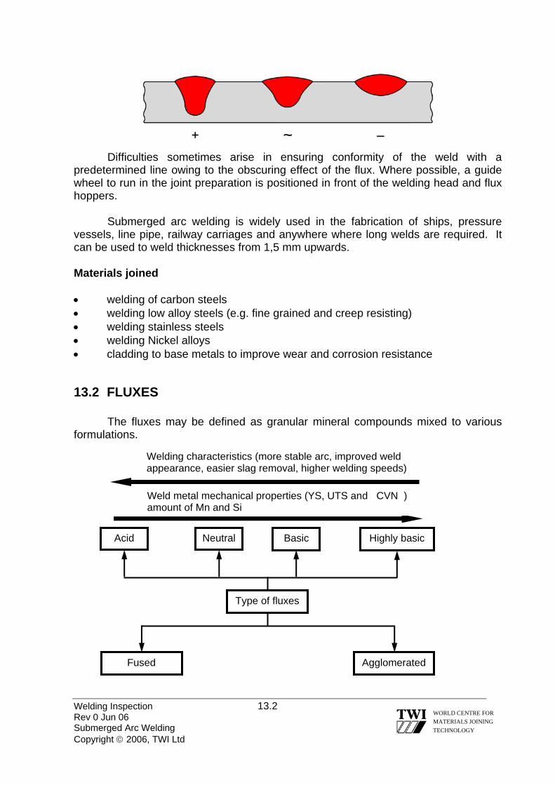
Difficulties sometimes arise in ensuring conformity of the weld with a predetermined line owing to the obscuring effect of the flux. Where possible, a guide wheel to run in the joint preparation is positioned in front of the welding head and flux hoppers.
Submerged arc welding is widely used in the fabrication of ships, pressure vessels, line pipe, railway carriages and anywhere where long welds are required. It can be used to weld thicknesses from 1,5 mm upwards. Materials joined • welding of carbon steels • welding low alloy steels (e.g. fine grained and creep resisting) • welding stainless steels • welding Nickel alloys • cladding to base metals to improve wear and corrosion resistance
13.2 FLUXES
The fluxes may be defined as granular mineral compounds mixed to various formulations.
Welding Inspection 13.2 Rev 0 Jun 06 Submerged Arc Welding Copyright © 2006, TWI Ltd
WORLD CENTRE FOR MATERIALS JOINING TECHNOLOGY
Type of fluxes
Agglomerated Fused
Neutral Acid Basic Highly basic
Welding characteristics (more stable arc, improved weld appearance, easier slag removal, higher welding speeds)
Weld metal mechanical properties (YS, UTS and CVN ) amount of Mn and Si

Welding Inspection 13.3 Rev 0 Jun 06 Submerged Arc Welding Copyright © 2006, TWI Ltd
WORLD CENTRE FOR MATERIALS JOINING TECHNOLOGY
The fused fluxes are produced when the constituents are dry mixed and melted in an electric furnace and thereafter granulated by pouring the molten mixture into water or onto an ice block. Subsequently, these particles are crushed and screened to yield a uniform glass-like product. Advantages of fused fluxes: • good chemical homogeneity • less hygroscopic thus handling and storage are easier • allow fines (fine powders) to be removed without changes in composition • they can easily be recycled through the system without significant change in
particle size or composition Disadvantages of fused fluxes: • limitations in composition as some components such as basic carbonates
would be unable to withstand the melting process • difficult to add deoxidises and ferro-alloys (due to segregation or extremely high
loss) In case of agglomerated fluxes constituents may be bonded by mixing the dry constituents with Potassium or Sodium Silicate. This wet mixture is then pelletised, dried, crushed and screened to size.
Advantages of agglomerated fluxes:
• deoxidises and alloying elements can easily be added to the flux to adjust the weld metal composition
• allow a thicker flux layer when welding • can be identified by colour coding Disadvantages of agglomerated fluxes: • are generally more hygroscopic (requires baking) • gas may be evolved from the slag as it is melted, leading to porosity • there may be changes in weld metal chemical composition from the
segregation of fine particles produced by the mechanical handling of the granulated flux
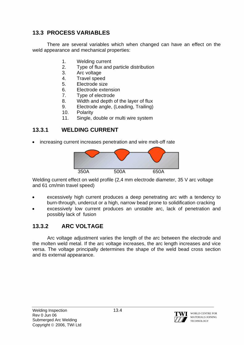
13.3 PROCESS VARIABLES There are several variables which when changed can have an effect on the weld appearance and mechanical properties: 1. Welding current 2. Type of flux and particle distribution 3. Arc voltage 4. Travel speed 5. Electrode size 6. Electrode extension 7. Type of electrode 8. Width and depth of the layer of flux
9. Electrode angle, (Leading, Trailing) 10. Polarity 11. Single, double or multi wire system
13.3.1 WELDING CURRENT • increasing current increases penetration and wire melt-off rate
350A 500A 650A Welding current effect on weld profile (2,4 mm electrode diameter, 35 V arc voltage and 61 cm/min travel speed) • excessively high current produces a deep penetrating arc with a tendency to
burn-through, undercut or a high, narrow bead prone to solidification cracking • excessively low current produces an unstable arc, lack of penetration and
possibly lack of fusion 13.3.2 ARC VOLTAGE
Arc voltage adjustment varies the length of the arc between the electrode and the molten weld metal. If the arc voltage increases, the arc length increases and vice versa. The voltage principally determines the shape of the weld bead cross section and its external appearance.
Welding Inspection 13.4 Rev 0 Jun 06 Submerged Arc Welding Copyright © 2006, TWI Ltd
WORLD CENTRE FOR MATERIALS JOINING TECHNOLOGY
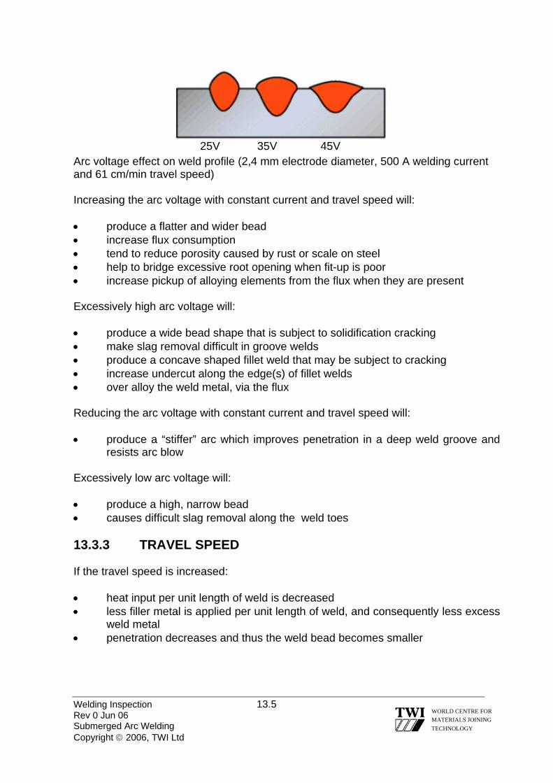
25V 35V 45V
Arc voltage effect on weld profile (2,4 mm electrode diameter, 500 A welding current and 61 cm/min travel speed)
Increasing the arc voltage with constant current and travel speed will: • produce a flatter and wider bead • increase flux consumption • tend to reduce porosity caused by rust or scale on steel • help to bridge excessive root opening when fit-up is poor • increase pickup of alloying elements from the flux when they are present Excessively high arc voltage will: • produce a wide bead shape that is subject to solidification cracking • make slag removal difficult in groove welds • produce a concave shaped fillet weld that may be subject to cracking • increase undercut along the edge(s) of fillet welds • over alloy the weld metal, via the flux Reducing the arc voltage with constant current and travel speed will: • produce a “stiffer” arc which improves penetration in a deep weld groove and
resists arc blow Excessively low arc voltage will: • produce a high, narrow bead • causes difficult slag removal along the weld toes 13.3.3 TRAVEL SPEED If the travel speed is increased: • heat input per unit length of weld is decreased • less filler metal is applied per unit length of weld, and consequently less excess
weld metal • penetration decreases and thus the weld bead becomes smaller
Welding Inspection 13.5 Rev 0 Jun 06 Submerged Arc Welding Copyright © 2006, TWI Ltd
WORLD CENTRE FOR MATERIALS JOINING TECHNOLOGY

30,5 cm/min 61 cm/min 122 cm/min Travel speed effect on weld profile (2,4 mm electrode diameter, 500 A welding current and 35V arc voltage) 13.3.4 ELECTRODE SIZE Electrode size affects: • the weld bead shape and the depth of penetration at a given current: a high current
density results in a “stiff” arc that penetrates into the base metal. Conversely, a lower current density in the same size electrode results in a “soft’ arc that is less penetrating.
• the deposition rate: at any given amperage setting, a small diameter electrode will have a higher current density and a higher deposition rate of molten metal than a larger diameter electrode. However, a larger diameter electrode can carry more current than a smaller electrode, so the larger electrode can ultimately produce a higher deposition rate at higher amperage
3,2 mm 4,0 mm 5,0 Electrode size effect on weld profile (600 A welding current, 30V arc voltage and 76 cm/min travel speed) 13.3.5 ELECTRODE EXTENSION
The electrode extension is the distance the continuous electrode protrudes beyond the contact tip. At high current densities, resistance heating of the electrode between the contact tip and the arc can be utilised to increase the electrode melting rate (as much as 25-50%). The longer the extension, the greater the amount of heating and the higher the melting rate. (see below )
Welding Inspection 13.6 Rev 0 Jun 06 Submerged Arc Welding Copyright © 2006, TWI Ltd
WORLD CENTRE FOR MATERIALS JOINING TECHNOLOGY

Welding Inspection 13.7 Rev 0 Jun 06 Submerged Arc Welding Copyright © 2006, TWI Ltd
WORLD CENTRE FOR MATERIALS JOINING TECHNOLOGY
13.3.6 TYPE OF ELECTRODE
An electrode with a low electrical conductivity, such as stainless steel, can with a normal electrode extension experience greater resistance heating. Thus for the same size electrode and current, the melting rate of a stainless steel electrode will be higher than that of a carbon steel electrode. 13.3.7 WIDTH AND DEPTH OF FLUX
The width and depth of the layer of granular flux influence the appearance and soundness of the finished weld as well as the welding action. If the granular layer is too deep, the arc is too confined and a rough weld with a rope-like appearance is likely to result, it may also produce local flat areas on the surface often referred to as gas flats. The gases generated during welding cannot readily escape, and the surface of the molten weld metal is irregularly distorted. If the granular layer is too shallow, the arc will not be entirely submerged in flux. Flashing and spattering will occur. The weld will have a poor appearance, and it may show porosity. 13.4 STORAGE AND CARE OF CONSUMABLES
Care must be given to fluxes supplied for SAW which, although they may be dry when packaged, may be exposed to high humidity during storage. In such cases they should be dried in accordance with the manufacturer's recommendations before use, or porosity or cracking may result.
Ferrous wire coils supplied as continuous feeding electrodes are usually copper coated. This provides some corrosion resistance, ensures good electrical contacts and helps in smooth feeding. Rust and mechanical damage should be avoided in such products, as they will both interrupt smooth feeding of the electrode. Rust will be detrimental to weld quality generally since rust is a hygroscopic material (may contain or absorb moisture) and thus it can lead to hydrogen induced cracking.
Contamination by carbon containing materials such as oil, grease, paint and drawing lubricants is especially harmful with ferrous metals. Carbon pick-up in the weld metal can cause a marked and usually undesirable change in properties. Such contaminants may also result in hydrogen being absorbed in the weld pool.
Welders should always follow the manufacturer's recommendations for consumables storage and handling. 13.5 POWER SOURCES
In arc welding it is principally the current which determines the amount of heat generated and this controls the melting of the electrode and parent metal and also such factors as penetration and bead shape and size. Voltage and arc length are also important factors with increasing voltage leading to increasing arc length and
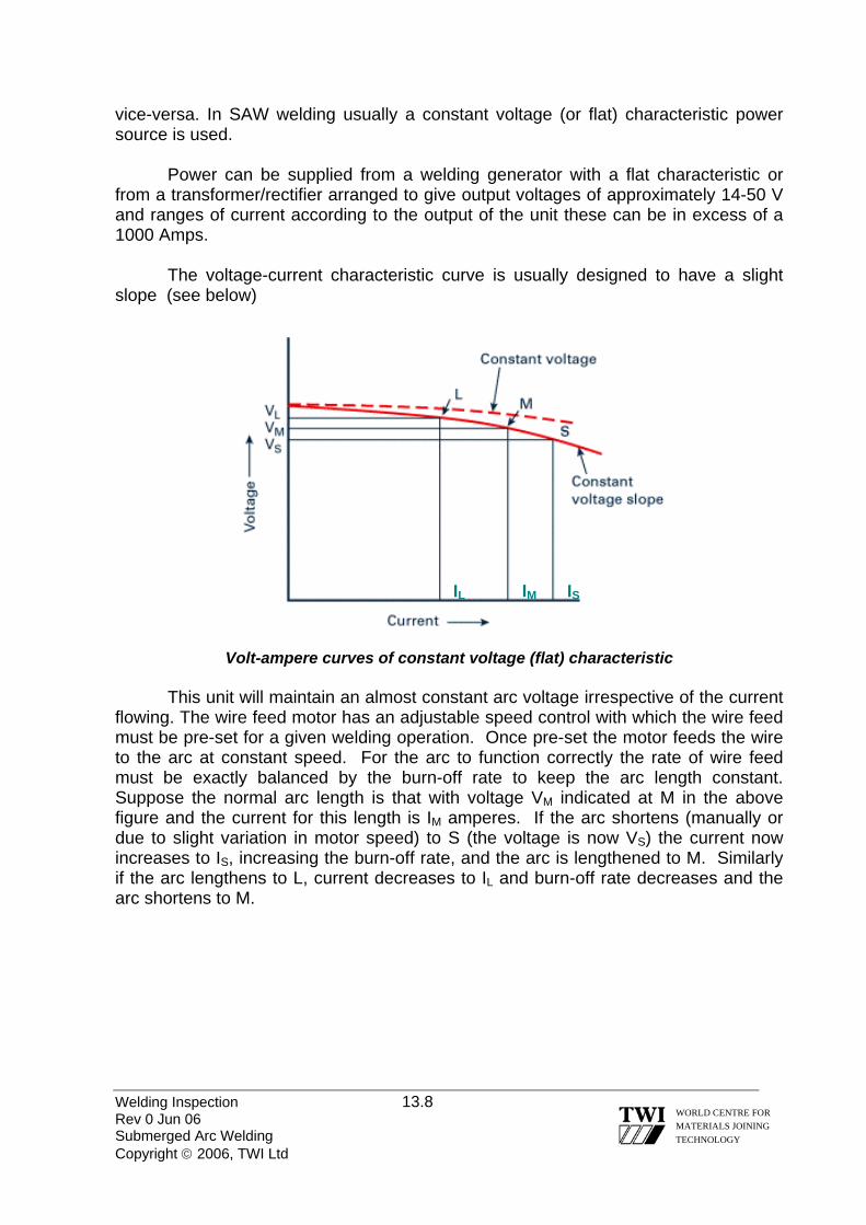
vice-versa. In SAW welding usually a constant voltage (or flat) characteristic power source is used.
Power can be supplied from a welding generator with a flat characteristic or from a transformer/rectifier arranged to give output voltages of approximately 14-50 V and ranges of current according to the output of the unit these can be in excess of a 1000 Amps.
The voltage-current characteristic curve is usually designed to have a slight slope (see below)
IM ISIL
Volt-ampere curves of constant voltage (flat) characteristic
This unit will maintain an almost constant arc voltage irrespective of the current flowing. The wire feed motor has an adjustable speed control with which the wire feed must be pre-set for a given welding operation. Once pre-set the motor feeds the wire to the arc at constant speed. For the arc to function correctly the rate of wire feed must be exactly balanced by the burn-off rate to keep the arc length constant. Suppose the normal arc length is that with voltage VM indicated at M in the above figure and the current for this length is IM amperes. If the arc shortens (manually or due to slight variation in motor speed) to S (the voltage is now VS) the current now increases to IS, increasing the burn-off rate, and the arc is lengthened to M. Similarly if the arc lengthens to L, current decreases to IL and burn-off rate decreases and the arc shortens to M.
Welding Inspection 13.8 Rev 0 Jun 06 Submerged Arc Welding Copyright © 2006, TWI Ltd
WORLD CENTRE FOR MATERIALS JOINING TECHNOLOGY
Welding Inspection Rev 0 Jun 06 Copyright © 2006, TWI Ltd
WORLD CENTRE FOR MATERIALS JOINING TECHNOLOGY
Section 14
Welding Consumables

Welding Inspection 14.1 Rev 0 Jun 06 Welding Consumables Copyright © 2006, TWI Ltd
WORLD CENTRE FOR MATERIALS JOINING TECHNOLOGY
14.0 WELDING CONSUMABLES 14.1 INTRODUCTION
Welding consumables are defined as all those things that are used up in the production of a weld.
This list could include many things including electrical energy, however we normally refer to welding consumables as those things used up by a particular welding process. 14.1.1 MMA ELECTRODES
MMA electrodes can be categorised according to the type of covering they have and consequently the characteristics that it confers. For C-Mn and low alloy steels there are 3 generic types of electrodes, namely: - Cellulosic electrodes Rutile electrode Basic electrodes
These generic names indicate the type of mineral/compound that is dominant in
the covering. 14.1.2 COVERED ELECTRODE MANUFACTURE Electrode manufacturers produce electrodes by: Straightening and cutting core wire to standard lengths
(typically 300, 350, & 450mm depending on electrode classification & diameter) Making a ‘dry’ mix of powdered compounds/minerals
(precise levels of additions depend on individual manufacturers formulations) Making a ‘wet’ mix by adding the dry powders to a liquid binder Extruding the covering (concentrically) on to the core wire Hardening the covering by drying the electrodes Carrying out batch tests - as required for electrode certification Packing the electrodes into suitable containers

Welding Inspection 14.2 Rev 0 Jun 06 Welding Consumables Copyright © 2006, TWI Ltd
WORLD CENTRE FOR MATERIALS JOINING TECHNOLOGY
1. For low hydrogen electrodes this is a high temperature bake - ≥ ~450ºC
Vacuum packed electrodes are packed in small quantities into packaging that is immediately vacuum sealed – to ensure no moisture pick-up
Electrodes that need to be re-baked are packed into standard packets and as this
may be some time after baking, and the packaging may not be sealed, they do not reach the end-user in a guaranteed low hydrogen condition, they therefore require re-baking at a typical temperature of 350ºC for approximately 2 hours, Note! You should always follow the manufacturers recommendations.
2. For individual batch certification this will require the manufacture of a test pad for
chemical analysis and may require manufacture of a test weld from which a tensile test and Charpy V-notch test pieces are tested
14.1.3 ELECTRODE COVERINGS
Core wires used for most C-Mn electrodes, and some low alloy steel electrodes, is a very low C steel* and it is the formulation of the covering that determines the composition of the deposited weld metal and the operating characteristics of the electrode. (* Typically ~ 0.06%C, ~0.5%Mn)
The flux covering on an electrode is formulated to aid the manufacturing process and to provide a number of functions during welding. The major welding functions are: 1. To facilitate arc ignition/re-ignition and give arc stabilisation 2. To generate gas for shielding the arc and molten metal from contamination by air 3. To interact with the molten weld metal to give de-oxidation and flux impurities into
the slag to cleanse/refine the molten weld metal 4. To form a slag for protection of the hot weld metal from air contamination 5. To provide elements to give the weld metal the required mechanical properties 6. To enable positional welding by means of slag formers that freeze a temperatures
above the solidification temperature range of the weld metal

14.1.4 INSPECTION POINTS FOR MMA CONSUMABLES
1. Size: Wire Diameter & length.
Welding Inspection 14.3 Rev 0 Jun 06 Welding Consumables Copyright © 2006, TWI Ltd
WORLD CENTRE FOR MATERIALS JOINING TECHNOLOGY
2. Condition: Cracks, chips & concentricity.
3. Type (Specification): Correct specification/code.
E 46 3 B
Checks should also be made to ensure that basic electrodes have been
through the correct pre-use procedure. Having been baked to the correct temperature (typically 300-350°C) for 1 hour and then held in a holding oven at 150 °C before being issued to the welders in heated quivers. Most electrode flux coatings will deteriorate rapidly when damp and care should be taken to inspect storage facilities to ensure that they are adequately dry, and that all electrodes are stored in conditions of controlled temperature and humidity.

Welding Inspection 14.4 Rev 0 Jun 06 Welding Consumables Copyright © 2006, TWI Ltd
WORLD CENTRE FOR MATERIALS JOINING TECHNOLOGY
14.2 CELLULOSIC ELECTRODES
Cellulose is the principal substance in this type of electrode and comprising typically ~ 40% of the flux constituents.
Cellulose is an organic material (naturally occurring) such as cotton and wood, but it is wood pulp that is the principal source of cellulose used in the manufacture of electrode coverings. The main characteristics of Cellulosic electrodes are: Cellulose breaks down during welding and produces carbon monoxide &
dioxide and hydrogen Hydrogen provides part of the gas shielding function and gives a relatively high
arc voltage The high arc voltage gives the electrode a ‘hard’ and forceful arc with good
penetration/fusion ability The volume of slag formed is relatively small
Cellulosic electrodes cannot be baked during manufacture or before welding
because this would destroy the cellulose; the manufacturing procedure is to ‘harden’ the coating by drying (typically at 70 to 100ºC)
Because of the high hydrogen levels there is always some risk of H cracking
which requires control measures such as ‘hot-pass’ welding to facilitate the rapid escape of hydrogen
Because of the risk of H cracking there are limits on the strength/composition
and thickness of steels on which they can be used (electrode are manufactured in classes E60xx, E70xx, E80xx & E90xx but both
lower strength grades tend to be the most commonly used) High toughness at low temperatures cannot be consistently achieved from this
type of electrode (typically only down to about -20ºC) 14.2.1 APPLICATIONS OF CELLULOSIC ELECTRODES
Cellulosic electrodes have characteristics that enable them to be used for vertical-down welding at fast travel speed but with low risk of lack-of-fusion because of their forceful arc.
The ‘niche’ application for this type of electrode is girth seam welding of large diameter steel pipes for overland pipelines (Transco (BGAS) P2, BS 4515 & API 1104

Welding Inspection 14.5 Rev 0 Jun 06 Welding Consumables Copyright © 2006, TWI Ltd
WORLD CENTRE FOR MATERIALS JOINING TECHNOLOGY
applications). No other type of electrode has the ability to allow root pass welding at high speed and still give good root penetration when the root gap is less than ideal.
Because of their penetration ability these electrodes have also found application on oil storage tanks – for vertical and circumferential seam welding of the upper/thinner courses for which preparations with large root faces or square edge preparations are used. 14.3 RUTILE ELECTRODES
Rutile is a mineral that consists of about 90% titanium dioxide (TiO2) and is present in C & C-Mn steel rutile electrodes at typically ~50%. Characteristics of rutile electrodes are: They have a very smooth and stable arc and produce a relatively thin slag
covering that is easy to remove They give a smooth weld profile
They are regarded as the most ‘user-friendly’ of the various electrode types
They have relatively high ‘combined moisture’ content and because they
contain typically up to ~10% cellulose they cannot be baked and consequently they do not give a low H weld deposit
Because of the risk of cracking they are not designed for welding of high
strength or thick section steel (although electrodes are manufactured in classes E60xx, E70xx, E80xx the
E60xx grade is by far the most commonly used) They do not give high toughness at low temperatures (typically only down to
about -20ºC) The above listed characteristics mean that this type of electrode is used for
general-purpose fabrication of unalloyed, low strength steels in relatively thin sections (typically ≤ ~13mm). 14.3.1 RUTILE ELECTRODE VARIANTS
By adding iron powder to the covering a range of thick-coated electrodes have been produced in order to enhance productivity.
Such electrodes give weld deposits that weigh between ~135 and 190% of their core wire weight and so referred to as ‘high recovery’ electrodes, or more specifically for example ‘ a 170% recovery electrode’.

Welding Inspection 14.6 Rev 0 Jun 06 Welding Consumables Copyright © 2006, TWI Ltd
WORLD CENTRE FOR MATERIALS JOINING TECHNOLOGY
The weld deposit from such electrodes can be relatively large and fluid and this restricts welding to the flat position and for standing fillets for electrodes with the highest recovery rates.
In all other respects these electrodes have the characteristics listed for standard rutile electrodes. 14.4 BASIC ELECTRODES
Basic electrodes are so named because the covering is made with a high proportion of basic minerals/compounds (alkaline compounds), such as calcium carbonate (CaCO3), magnesium carbonate (MgCO3) and calcium fluoride (CaF2).
A fully basic electrode covering will be made up with about 60% of these basic minerals/compounds. Characteristics of basic electrodes are: The basic slag that forms when the covering melts reacts with impurities, such
as sulphur and phosphorus, and also reduces the oxygen content of the weld metal by de-oxidation
The relatively clean weld metal that is deposited gives a very significant
improvement in weld metal toughness (C-Mn electrodes with Ni additions can give good toughness down to ~ -90°C)
They can be baked at relatively high temperatures without any of the
compounds present in the covering being destroyed, thereby giving low moisture content in the covering and low hydrogen levels in weld metal
In order to maintain the electrodes in a low hydrogen condition they need to be
protected from moisture pick-up
By means of baking before use (typically at ~350°C), transferring to a holding oven (typically at ~120°C) and issued in small quantities and/or using heated quivers (‘portable ovens’) at the work station (typically ~70°C)
By use of vacuum packed electrodes that do not need to be re-baked before use
Basic slag is relatively viscous and thick which means that electrode
manipulation requires more skill and should be used with a short arc to minimise the risk of porosity
The surface profile of weld deposits from basic electrodes tends to be convex
and slag removal requires more effort

Welding Inspection 14.7 Rev 0 Jun 06 Welding Consumables Copyright © 2006, TWI Ltd
WORLD CENTRE FOR MATERIALS JOINING TECHNOLOGY
Metal powder electrodes contain an addition of metal powder to the flux coating to increase the maximum permissible welding current level. Thus, for a given electrode size, the metal deposition rate and efficiency (percentage of the metal deposited) are increased compared with an electrode containing no iron powder in the coating. The slag is normally easily removed. Iron powder electrodes are mainly used in the flat and H/V positions to take advantage of the higher deposition rates. Efficiencies as high as 130 to 140% can be achieved for rutile and basic electrodes without marked deterioration of the arcing characteristics but the arc tends to be less forceful which reduces bead penetration. 14.4.1 APPLICATIONS OF BASIC ELECTRODES
Basic electrodes have to be used for all applications that require good fracture toughness at temperatures below ~ -20°C.
To avoid the risk of hydrogen cracking basic electrodes have to be used for welding hardenable steels (most C-Mn & all low alloy steels) and for most steels when the joint thickness is greater than about 15mm. 14.5 CLASSIFICATION OF ELECTRODES National standards for electrodes that are used for welding are:
EN 499 Covered electrodes for manual metal arc welding of non- alloy and fine grain steels
AWS A5.1 Specification for carbon steel electrodes for shielded metal
arc welding AWS A5.5 Specification for low-alloy steel electrodes for shielded
metal arc welding
Electrode classification is based on tests specified by the standard on weld deposits made with each type of covered electrode. The standards require chemical analysis and mechanical tests and electrode manufacturers tend to dual certify electrodes, wherever possible, to both the European and American standards

Welding Inspection 14.8 Rev 0 Jun 06 Welding Consumables Copyright © 2006, TWI Ltd
WORLD CENTRE FOR MATERIALS JOINING TECHNOLOGY
14.5.1 EN 499 EN 499 - Covered electrodes for manual metal arc welding of non-alloy and fine grain steels (See Figure 1)
This is the designation that manufacturers print on to each electrode so that it can be easily identified. The classification is split into two sections, namely:
Compulsory Section - this includes the symbols for: type of product strength impact properties chemical composition type of electrode covering
Optional Section - this includes the symbols for: weld metal recovery the type of current the welding positions the hydrogen content
The designation, Compulsory (Strength, Toughness & Coating including any
light alloying elements) must be identified on the electrode, however the optional (position, hydrogen levels etc are not mandatory and may not be shown on all electrodes.

Figure 1 The electrode classification system of EN 499
Welding Inspection 14.9 WORLD CENTRE FOR MATERIALS JOINING TECHNOLOGY
Rev 0 Jun 06 Welding Consumables Copyright © 2006, TWI Ltd
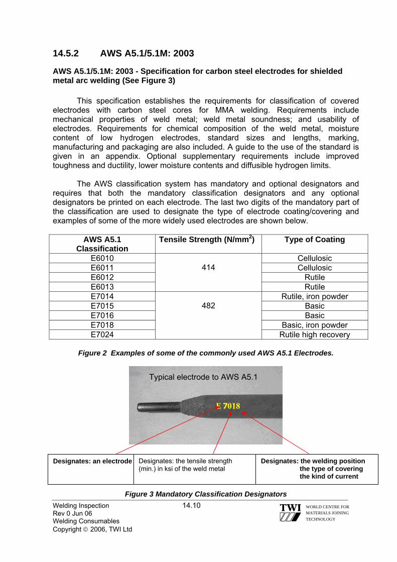
14.5.2 AWS A5.1/5.1M: 2003
AWS A5.1/5.1M: 2003 - Specification for carbon steel electrodes for shielded metal arc welding (See Figure 3)
This specification establishes the requirements for classification of covered
electrodes with carbon steel cores for MMA welding. Requirements include mechanical properties of weld metal; weld metal soundness; and usability of electrodes. Requirements for chemical composition of the weld metal, moisture content of low hydrogen electrodes, standard sizes and lengths, marking, manufacturing and packaging are also included. A guide to the use of the standard is given in an appendix. Optional supplementary requirements include improved toughness and ductility, lower moisture contents and diffusible hydrogen limits.
The AWS classification system has mandatory and optional designators and requires that both the mandatory classification designators and any optional designators be printed on each electrode. The last two digits of the mandatory part of the classification are used to designate the type of electrode coating/covering and examples of some of the more widely used electrodes are shown below.
AWS A5.1 Classification
Tensile Strength (N/mm2) Type of Coating
E6010 414
Cellulosic E6011 Cellulosic E6012 Rutile E6013 Rutile E7014
482 Rutile, iron powder
E7015 Basic E7016 Basic E7018 Basic, iron powder E7024 Rutile high recovery
Figure 2 Examples of some of the commonly used AWS A5.1 Electrodes.
Typical electrode to AWS A5.1
Welding Inspection 14.10 Rev 0 Jun 06 Welding Consumables Copyright © 2006, TWI Ltd
WORLD CENTRE FOR MATERIALS JOINING TECHNOLOGY
Figure 3 Mandatory Classification Designators
Designates: an electrode Designates: the tensile strength (min.) in ksi of the weld metal
Designates: the welding position the type of covering the kind of current

Welding Inspection 14.11 Rev 0 Jun 06 Welding Consumables Copyright © 2006, TWI Ltd
WORLD CENTRE FOR MATERIALS JOINING TECHNOLOGY
General Description EN 499 AWS A5.1 / 5.5 Cellulosic electrodes
(For vertical-down welding
‘Stovepipe welding’ of pipeline girth welds)
E 38 3 C 21 E 42 3 Z C 21 E 46 3 Z C 21 E 42 3 C 25 E 46 4 1Ni C 25
E6010 E7010-G E8010-G E7010-P 1 * E8010-P 1 *
* P = specially designated piping electrodes Rutile electrodes
(For general purpose fabrication of low strength steels – can be used for all positions except vertical-down)
E 38 2 R 12 E 42 0 R 12
E6013 E6013
Heavy coated rutile electrodes
(Iron-powder electrodes)
(For higher productivity welding for general fabrication of low strength
steels – can generally only be used for downhand or standing fillet
welding)
E 42 0 RR 13 E 42 0 RR 74
E6013 E7024
Basic electrodes
(For higher strength steels, thicker section steels where there is risk of H cracking; for all applications requiring good fracture toughness)
E 42 2 B 12 H10 E 42 4 B 32 H5 E 46 6 Mn1Ni B 12 H5 E 55 6 Mn1Ni B 32 H5 E 46 5 1Ni B 45 H5* E 55 5 Z 2Ni B 45 H5* E 62 5 Z 2Ni B 45 H5*
E7016 E7018 E 7016-G E8018-C1 E8018-G E9018-G E10018-G
* Vertical-down low H electrodes
Table 1 Common electrodes that are classified to BS EN 499 & AWS A5.1 / 5.5
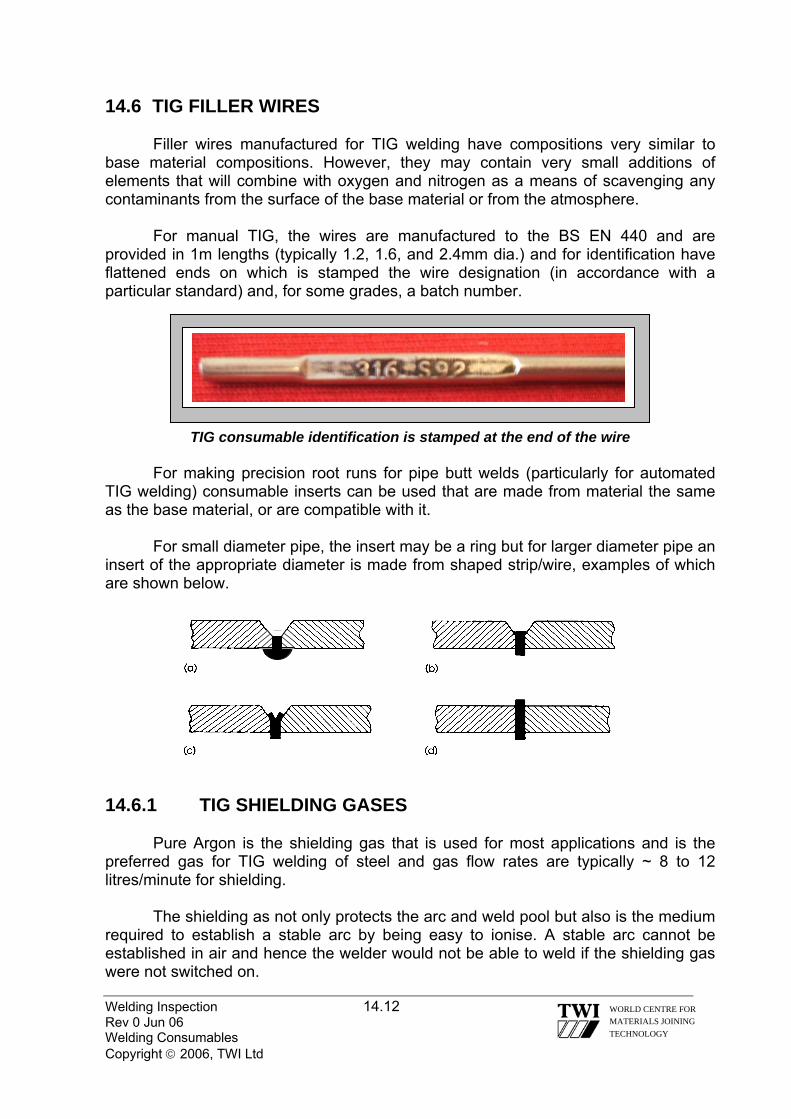
14.6 TIG FILLER WIRES
Filler wires manufactured for TIG welding have compositions very similar to base material compositions. However, they may contain very small additions of elements that will combine with oxygen and nitrogen as a means of scavenging any contaminants from the surface of the base material or from the atmosphere.
For manual TIG, the wires are manufactured to the BS EN 440 and are provided in 1m lengths (typically 1.2, 1.6, and 2.4mm dia.) and for identification have flattened ends on which is stamped the wire designation (in accordance with a particular standard) and, for some grades, a batch number.
Welding Inspection 14.12 Rev 0 Jun 06 Welding Consumables Copyright © 2006, TWI Ltd
WORLD CENTRE FOR MATERIALS JOINING TECHNOLOGY
TIG consumable identification is stamped at the end of the wire
For making precision root runs for pipe butt welds (particularly for automated TIG welding) consumable inserts can be used that are made from material the same as the base material, or are compatible with it.
For small diameter pipe, the insert may be a ring but for larger diameter pipe an insert of the appropriate diameter is made from shaped strip/wire, examples of which are shown below.
14.6.1 TIG SHIELDING GASES
Pure Argon is the shielding gas that is used for most applications and is the preferred gas for TIG welding of steel and gas flow rates are typically ~ 8 to 12 litres/minute for shielding.
The shielding as not only protects the arc and weld pool but also is the medium required to establish a stable arc by being easy to ionise. A stable arc cannot be established in air and hence the welder would not be able to weld if the shielding gas were not switched on.

Welding Inspection 14.13 Rev 0 Jun 06 Welding Consumables Copyright © 2006, TWI Ltd
WORLD CENTRE FOR MATERIALS JOINING TECHNOLOGY
Argon with a Helium addition – typically ~30% may be used when a ‘hotter’ arc is needed such as when welding metals with high thermal conductivity, such as copper/copper alloys or thicker section aluminium/aluminium alloys.
There are some circumstances when special shielding gases are beneficial, for example:
Ar + 3 to 5% H for austenitic stainless steels and Cu-Ni alloys Ar + ~3% N for duplex stainless steels
14.6.2 TIG BACK-PURGING
For most materials, the underside of a weld root bead needs to be protected by an inert gas (a back-purge) – typically ~ 6 to 8 litres/minute during welding.
For C steels and low alloy steels with total alloying additions ≤ 2.5% it may not always be necessary to use a back-purge but for higher alloyed steels and most other materials there may be excessive oxidation – and risk of lack of fusion if a back-purge is not used. 14.7 MIG/MAG FILLER WIRES
Solid filler wires manufactured for MIG/MAG generally have chemical compositions that have been formulated for particular base materials and the wires have compositions similar to these base materials. Solid wires for welding steels with active shielding gases are deoxidised with manganese and silicon to avoid porosity. There may also be titanium and aluminium additions. Mild steel filler wires are available with different levels of deoxidants, known as double or triple de-oxidised wires. More highly deoxidised wires are more expensive but are more tolerant of the plate surface condition, e.g. mill scale, surface rust, oil, paint and dust. There may, therefore, be a reduction in the amount of cleaning of the steel before welding.
These deoxidiser additions yield a small amount of 'glassy' slag on the surface of the weld deposit, commonly referred to as silica deposits. These small pockets of slag are easily removed with light brushing; but when galvanising or painting after welding, it is necessary to use shot blasting. During welding, it is common practice to weld over these small islands since they do not represent a thick slag, and they usually spall off during the contraction of the weld bead. However, when multipass welding, the slag level may build up to an unacceptable level causing weld defects and unreliable arc starting.
Steel wires usually have a flash coating of copper to improve current pick-up and to extend the shelf life of the wire. However, the copper coating can sometimes flake off and be drawn into the liner and wire feed mechanism, particularly if there is misalignment in the wire feed system. This may cause clogging and erratic wire feed. Uncoated wires are available as an alternative, although electrical contact may not be
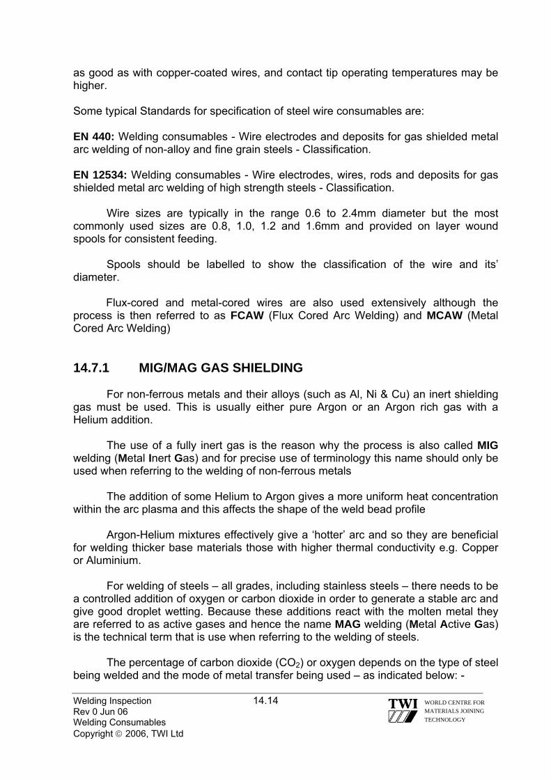
Welding Inspection 14.14 Rev 0 Jun 06 Welding Consumables Copyright © 2006, TWI Ltd
WORLD CENTRE FOR MATERIALS JOINING TECHNOLOGY
as good as with copper-coated wires, and contact tip operating temperatures may be higher. Some typical Standards for specification of steel wire consumables are: EN 440: Welding consumables - Wire electrodes and deposits for gas shielded metal arc welding of non-alloy and fine grain steels - Classification. EN 12534: Welding consumables - Wire electrodes, wires, rods and deposits for gas shielded metal arc welding of high strength steels - Classification.
Wire sizes are typically in the range 0.6 to 2.4mm diameter but the most commonly used sizes are 0.8, 1.0, 1.2 and 1.6mm and provided on layer wound spools for consistent feeding.
Spools should be labelled to show the classification of the wire and its’ diameter.
Flux-cored and metal-cored wires are also used extensively although the process is then referred to as FCAW (Flux Cored Arc Welding) and MCAW (Metal Cored Arc Welding) 14.7.1 MIG/MAG GAS SHIELDING
For non-ferrous metals and their alloys (such as Al, Ni & Cu) an inert shielding gas must be used. This is usually either pure Argon or an Argon rich gas with a Helium addition.
The use of a fully inert gas is the reason why the process is also called MIG welding (Metal Inert Gas) and for precise use of terminology this name should only be used when referring to the welding of non-ferrous metals
The addition of some Helium to Argon gives a more uniform heat concentration within the arc plasma and this affects the shape of the weld bead profile
Argon-Helium mixtures effectively give a ‘hotter’ arc and so they are beneficial for welding thicker base materials those with higher thermal conductivity e.g. Copper or Aluminium.
For welding of steels – all grades, including stainless steels – there needs to be a controlled addition of oxygen or carbon dioxide in order to generate a stable arc and give good droplet wetting. Because these additions react with the molten metal they are referred to as active gases and hence the name MAG welding (Metal Active Gas) is the technical term that is use when referring to the welding of steels.
The percentage of carbon dioxide (CO2) or oxygen depends on the type of steel being welded and the mode of metal transfer being used – as indicated below: -
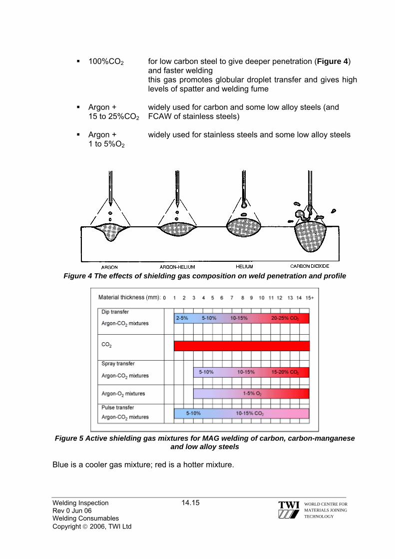
100%CO2 for low carbon steel to give deeper penetration (Figure 4)
and faster welding this gas promotes globular droplet transfer and gives high levels of spatter and welding fume
Argon + widely used for carbon and some low alloy steels (and
15 to 25%CO2 FCAW of stainless steels)
Argon + widely used for stainless steels and some low alloy steels 1 to 5%O2
Figure 4 The effects of shielding gas composition on weld penetration and profile
Figure 5 Active shielding gas mixtures for MAG welding of carbon, carbon-manganese
and low alloy steels Blue is a cooler gas mixture; red is a hotter mixture.
Welding Inspection 14.15
WORLD CENTRE FOR MATERIALS JOINING TECHNOLOGY
Rev 0 Jun 06 Welding Consumables Copyright © 2006, TWI Ltd

Gas mixtures - Helium in place of argon gives a hotter arc, more fluid weld pool and better weld profile. These quaternary mixtures permit higher welding speeds, but may not be suitable for thin sections. 14.7.1.1 STAINLESS STEELS
Austenitic stainless steels are typically welded with argon-CO2 /O2 mixtures for spray transfer, or argon-helium-CO2 mixtures for all modes of transfer. The oxidising potential of the mixtures are kept to a minimum (2-2.5% maximum CO2 content) in order to stabilise the arc, but with the minimum effect on corrosion performance. Because austenitic steels have a high thermal conductivity, the addition of helium helps to avoid lack of fusion defects and overcome the high heat dissipation into the material. Helium additions are up to 85%, compared with ~25% for mixtures used for carbon and low alloy steels. CO2 -containing mixtures are sometimes avoided to eliminate potential carbon pick-up.
Figure 6 Active shielding gas mixtures for MAG welding of stainless steels
Blue is a cooler gas mixture; red is a hotter mixture.
For martensitic and duplex stainless steels, specialist advice should be sought. Some Ar-He mixtures containing up to 2.5%N2 are available for welding duplex stainless steels. 14.7.1.2 LIGHT ALLOYS, E.G. ALUMINIUM AND MAGNESIUM, AND COPPER AND NICKEL AND THEIR ALLOYS
Inert gases are used for light alloys and alloys that are sensitive to oxidation. Welding grade inert gases should be purchased rather than commercial purity to ensure good weld quality. Argon:
Argon can be used for aluminium because there is sufficient surface oxide available to stabilise the arc. For materials that are sensitive to oxygen, such as titanium and nickel alloys, arc stability may be difficult to achieve with inert gases in some applications.
Welding Inspection 14.16 WORLD CENTRE FOR MATERIALS JOINING TECHNOLOGY
Rev 0 Jun 06 Welding Consumables Copyright © 2006, TWI Ltd

The density of argon is approximately 1.4 times that of air. Therefore, in the downhand position, the relatively heavy argon is very effective at displacing air. A disadvantage is that when working in confined spaces, there is a risk of argon building up to dangerous levels and asphyxiating the welder. Argon-helium mixtures:
Argon is most commonly used for MIG welding of light alloys, but some advantage can be gained by the use of helium and argon/helium mixtures. Helium possesses a higher thermal conductivity than argon. The hotter weld pool produces improved penetration and/or an increase in welding speed. High helium contents give a deep broad penetration profile, but produce high spatter levels. With less than 80% argon, a true spray transfer is not possible. With globular-type transfer, the welder should use a 'buried' arc to minimise spatter. Arc stability can be problematic in helium and argon-helium mixtures, since helium raises the arc voltage, and therefore there is a larger change in arc voltage with respect to arc length. Helium mixtures require higher flow rates than argon shielding in order to provide the same gas protection.
There is a reduced risk of lack of fusion defects when using argon-helium mixtures, particularly on thick section aluminium. Ar-He gas mixtures will offset the high heat dissipation in material over about 3mm thickness.
Figure 7 Inert shielding gas mixtures for MIG welding of aluminium, magnesium,
titanium, nickel and copper alloys Blue is a cooler gas mixture; red is a hotter mixture.
A summary table of shielding gases and mixtures used for different base materials is given in Table 2.
Welding Inspection 14.17 WORLD CENTRE FOR MATERIALS JOINING TECHNOLOGY
Rev 0 Jun 06 Welding Consumables Copyright © 2006, TWI Ltd
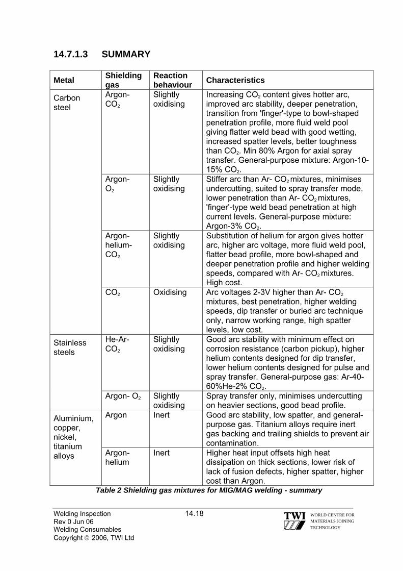
Welding Inspection 14.18 Rev 0 Jun 06 Welding Consumables Copyright © 2006, TWI Ltd
WORLD CENTRE FOR MATERIALS JOINING TECHNOLOGY
14.7.1.3 SUMMARY Metal Shielding
gas Reaction behaviour Characteristics
Carbon steel
Argon- CO2
Slightly oxidising
Increasing CO2 content gives hotter arc, improved arc stability, deeper penetration, transition from 'finger'-type to bowl-shaped penetration profile, more fluid weld pool giving flatter weld bead with good wetting, increased spatter levels, better toughness than CO2. Min 80% Argon for axial spray transfer. General-purpose mixture: Argon-10-15% CO2.
Argon- O2
Slightly oxidising
Stiffer arc than Ar- CO2 mixtures, minimises undercutting, suited to spray transfer mode, lower penetration than Ar- CO2 mixtures, 'finger'-type weld bead penetration at high current levels. General-purpose mixture: Argon-3% CO2.
Argon-helium- CO2
Slightly oxidising
Substitution of helium for argon gives hotter arc, higher arc voltage, more fluid weld pool, flatter bead profile, more bowl-shaped and deeper penetration profile and higher welding speeds, compared with Ar- CO2 mixtures. High cost.
CO2 Oxidising Arc voltages 2-3V higher than Ar- CO2 mixtures, best penetration, higher welding speeds, dip transfer or buried arc technique only, narrow working range, high spatter levels, low cost.
Stainless steels
He-Ar- CO2
Slightly oxidising
Good arc stability with minimum effect on corrosion resistance (carbon pickup), higher helium contents designed for dip transfer, lower helium contents designed for pulse and spray transfer. General-purpose gas: Ar-40-60%He-2% CO2.
Argon- O2 Slightly oxidising
Spray transfer only, minimises undercutting on heavier sections, good bead profile.
Aluminium, copper, nickel, titanium alloys
Argon Inert Good arc stability, low spatter, and general-purpose gas. Titanium alloys require inert gas backing and trailing shields to prevent air contamination.
Argon-helium
Inert Higher heat input offsets high heat dissipation on thick sections, lower risk of lack of fusion defects, higher spatter, higher cost than Argon.
Table 2 Shielding gas mixtures for MIG/MAG welding - summary

14.8 SAW FILLER WIRES
Filler wires for SAW are made to AWS and EN standards and the most commonly used sizes are 2.4, 3.2, 4.0 and 5.0 mm diameter and are available for welding a wide range of steels and some non-ferrous applications, they have compositions similar to the base material but for certification standards require flux/wire weld metal deposits to be made for analysis and testing as required 14.8.1 SAW FLUX TYPES Fluxes can be categorised into two types, namely fused and agglomerated (Agglomerated fluxes are sometimes called ‘bonded’ fluxes – particularly in the USA) 14.8.1.1 FUSED FLUX
This type are manufactured by mixing certain suitable minerals/compounds, fusing them together, crushing the solid mass and then sieving the crushed mass to recover granules within a particular size range. Fused fluxes have the following characteristics/properties:
They contain a high proportion of silica (up to ~ 60%) and so the flux
granules have similar in appearance to crushed glass – irregular shaped & hard - and have a smooth, and slightly shiny, surface
During re-circulation they have good resistance to breaking down into fine particles – referred to as ‘fines’
They have very low moisture content as manufactured and do not absorb moisture during exposure and so they should always give low hydrogen weld metal
They give welds beads with good surface finish and profile and de-slag easily
The main disadvantage of fused fluxes is that the compounds that give de-
oxidation cannot be added so that welds have high oxygen content and so steel weld metal does not have good toughness at sub-zero temperatures.
Welding Inspection 14.19 WORLD CENTRE FOR MATERIALS JOINING TECHNOLOGY
Rev 0 Jun 06 Welding Consumables Copyright © 2006, TWI Ltd

14.8.1.2 AGGLOMERATED FLUX
This type is manufactured by mixing fine powdered minerals/compounds, adding a wet binder and further mixing to form flux granules of the required size. These are dried/baked to remove moisture, sieved and packaged in sealed containers to ensure they are in ‘low hydrogen condition’ when supplied to the user.
Some of the minerals/compounds used in these fluxes cannot be subjected to the high temperatures required to make fused fluxes because they would break down and lose the properties that are needed during welding. Agglomerated fluxes have the following characteristics:
The granules tend to be more spherical and have a dull/matt finish The granules are consist of fine powders, weakly held together, and so are
quite soft and easily be broken down into fine powders during handling/re-circulation
Some of the compounds, and the binder itself, will tend to absorb moisture from the atmosphere if left exposed and a controlled handling procedure* is essential
The slag is less fluid than those generated by fused fluxes and the weld bead profile tends to be more convex and more effort is required to remove the slag
* Agglomerated fluxes are similar to fluxes used for basic covered electrodes and susceptible to moisture pick-up when they are cold and left exposed. A typical controlled handling practice is to transfer flux from the manufacturer’s drum/bag to a heated silo (~120 to 150°C). This acts like the holding oven for basic electrodes. Warm flux is transferred to the flux hopper on the machine (usually unheated) and at the end of a shift or when there is to be an interruption in welding, the hopper flux should be transferred to the silo.
The particular advantage of agglomerated fluxes is there ability to give weld metals with low oxygen content and this enables steel weld metal to be produced with good sub-zero toughness.
Welding Inspection 14.20 WORLD CENTRE FOR MATERIALS JOINING TECHNOLOGY
Rev 0 Jun 06 Welding Consumables Copyright © 2006, TWI Ltd

Welding Inspection 14.21 Rev 0 Jun 06 Welding Consumables Copyright © 2006, TWI Ltd
WORLD CENTRE FOR MATERIALS JOINING TECHNOLOGY
14.8.2 SAW FLUX BASICITY INDEX
Fluxes are often referred to as having a certain basicity or basicity index (BI).
The BI indicates the flux formulation according to the ratio of basic compounds to acid compounds and is used to give an indication of flux/weld reaction and can be interpreted as follows: -
A flux with a BI = 1 has an equal ratio of basic & acid compounds and thus is neither basic nor acid but said to be neutral*
A flux with BI > 1 has basic characteristics; fully basic fluxes have BI of ~3 to ~3.5
A flux with BI < 1 has acid characteristics Fused & agglomerated fluxes are mixed to produce fluxes referred to as
semi-basic * In the USA it is customary to use the terms ‘neutral’ to indicate that the flux has no significant influence on the composition by transfer of elements from flux to weld pool and ‘active’ to indicate that the flux does transfer some elements
Fused fluxes have acid characteristics and agglomerated fluxes have basic characteristics.
Although there are EN and AWS standards for flux classification, it is common UK practice to order fluxes by manufacturer name and use this name on WPS’s.

Welding Inspection Rev 0 Jun 06 Copyright © 2006, TWI Ltd
WORLD CENTRE FOR MATERIALS JOINING TECHNOLOGY
Section 15
Non-Destructive Testing
Welding Inspection 15.1 Rev 0 Jun 06 NDT Copyright © 2006, TWI Ltd
WORLD CENTRE FOR MATERIALS JOINING TECHNOLOGY
15.0 NON-DESTRUCTIVE EXAMINATION OF WELDS: APPRECIATION OF THE COMMON METHODS
Introduction Radiographic, ultrasonic, dye-penetrant and magnetic particle methods are briefly described below. The relative advantages and limitations of the methods are discussed in terms of their applicability to the examination of welds. 15.1 RADIOGRAPHIC METHODS In all cases radiographic methods as applied to welds involve passing a beam of penetrating radiation through the test object. The transmitted radiation is collected by some form of sensor, which is capable of measuring the relative intensities of penetrating radiations impinging upon it. In most cases this sensor will be a radiographic film, however the use of various electronic devices is on the increase. These devices facilitate so-called real time radiography and examples may be seen in the security check area at most airports. Digital technology has enabled the storing of radiographs using computers. The present discussion is confined to film radiography since this is still by far the most common method applied to welds. 15.1.1 SOURCES OF PENETRATING RADIATION Penetrating radiations may be generated from high-energy electron beams, in which case they are termed X-rays, or from nuclear disintegrations (atomic fission), in which case they are termed γ-rays. Other forms of penetrating radiation exist but they are of limited interest in weld radiography. 15.1.2 X-RAYS X-rays used in the industrial radiography of welds generally have photon energies in the range 30keV up to 20MeV. Up to 400keV they are generated by conventional X-ray tubes which dependant upon output may be suitable for portable or fixed installations. Portability falls off rapidly with increasing kilovoltage and radiation output. Above 400keV X-rays are produced using devices such as betatrons and linear accelerators. These devices are not generally suitable for use outside of fixed installations. All sources of X-rays produce a continuous spectrum of radiation, reflecting the spread of kinetic energies of electrons within the electron beam. Low energy radiations are more easily absorbed and the presence of low energy radiations, within the X-ray beam, gives rise to better radiographic contrast and therefore better radiographic sensitivity than is the case with γ-rays which are discussed below. Conventional X-ray units are capable of performing high quality radiography on steel of up to 60 mm thick, betatrons and linear accelerators are capable of penetrating in excess of 300 mm of steel.

Welding Inspection 15.2 Rev 0 Jun 06 NDT Copyright © 2006, TWI Ltd
WORLD CENTRE FOR MATERIALS JOINING TECHNOLOGY
15.1.3 γ-RAYS The early sources of γ-rays used in industrial radiography were in general composed of naturally occurring radium. The activity of these sources was not very high, therefore they were physically rather large by modern standards even for quite modest outputs of radiation and the radiographs produced by them were not of a particularly high standard. Radium sources were also extremely hazardous to the user due to the production of radioactive radon gas as a product of the fission reaction. Since the advent of the nuclear age it has been possible to artificially produce isotopes of much higher specific activity than those occurring naturally and which do not produce hazardous fission products. Unlike the X-ray sources γ-sources do not produce a continuous distribution of quantum energies. γ-sources produce a number of specific quantum energies which are unique for any particular isotope. Four isotopes are in common use for the radiography of welds, they are in ascending order of radiation energy: Thulium 90, Ytterbium 169, Iridium 192 and Cobalt 60. In terms of steel Thulium 90 is useful up to a thickness of 7mm or so, it’s energy is similar to that of 90keV X-rays and due to it’s high specific activity useful sources can be produced with physical dimensions of less than 0.5 mm. Ytterbium 169 has only fairly recently become available as an isotope for industrial use, it’s energy is similar to that of 120keV X-rays and it is useful for the radiography of steel up to approximately 12mm thick. Iridium 192 is probably the most commonly encountered isotopic source of radiation used in the radiographic examination of welds, it has a relatively high specific activity and high output sources with physical dimensions of 2-3 mm are in common usage, it’s energy is approximately equivalent to that of 500 keV X-rays and it is useful for the radiography of steel in the thickness range 10-75 mm. Cobalt 60 has an energy approximating to that of 1.2 MeV X-rays, due this relatively high energy suitable source containers are large and rather heavy. Cobalt 60 sources are for this reason not fully portable. They are useful for the radiography of steel in the thickness range 40-150 mm. The major advantages of using isotopic sources over X-rays are (a) The increased portability and (b) The lack of the need for a power source and (c) Lower initial equipment costs. Against this the quality of radiographs produced by γ-ray techniques is inferior to that produced by X-ray techniques, the hazards to personnel may be increased (if the equipment is not properly maintained, or if the operating personnel have insufficient training), and due to their limited useful lifespan new isotopes have to be purchased on a regular basis (so that the operating costs of a γ-ray source may exceed those of an X-ray source). 15.1.4 RADIOGRAPHY OF WELDS Radiographic techniques depend upon detecting differences in absorption of the beam i.e.: changes in the effective thickness of the test object, in order to reveal defective areas. Volumetric weld defects such as slag inclusions (except in some special cases where the slag absorbs radiation to a greater extent than does the weld metal) and various forms of gas porosity are easily detected by radiographic techniques due to the large negative absorption difference between the parent metal and the slag or gas. Planar defects such as cracks or lack of side wall or interun fusion are much less likely to be detected by radiography since such defects may

cause little or no change in the penetrated thickness. Where defects of this type are likely to occur other NDE techniques such as ultrasonic testing are preferable to radiography. This lack of sensitivity to planar defects makes radiography an unsuitable technique where a fitness-for-purpose approach is taken when assessing the acceptability of a weld. However, film radiography produces a permanent record of the weld condition, which can be archived for future reference; it also provides an excellent means of assessing the welder’s performance and for these reasons it is often still the preferred method for new construction. Figure 1: X-Ray Equipment Figure 2 Gamma-Ray Equipment
Figure 3: X-Ray of a welded seam showing Porosity
Welding Inspection 15.3 WORLD CENTRE FOR MATERIALS JOINING TECHNOLOGY
Rev 0 Jun 06 NDT Copyright © 2006, TWI Ltd

Welding Inspection 15.4 Rev 0 Jun 06 NDT Copyright © 2006, TWI Ltd
WORLD CENTRE FOR MATERIALS JOINING TECHNOLOGY
15.2 ULTRASONIC METHODS The velocity of ultrasound in any given material is a constant for that material and ultrasonic beams travel in straight lines in homogeneous materials. When ultrasonic waves pass from a given material with a given sound velocity to a second material with different velocity refraction and reflection of the sound beam will occur at the boundary between the two materials. The same laws of physics apply equally to ultrasonic waves as they do to light waves. Because ultrasonic waves are refracted at a boundary between two materials having different acoustic properties, probes may be constructed which can beam sound into a material at (within certain limits) any given angle. Because sound is reflected at a boundary between two materials having different acoustic properties ultrasound is a useful tool for the detection of weld defects. Because the velocity is a constant for any given material and because sound travels in a straight line (with the right equipment) ultrasound can also be utilised to give accurate positional information about a given reflector. Careful observation of the echo pattern of a given reflector and it’s behaviour as the ultrasonic probe is moved together with the positional information obtained above and a knowledge of the component history enables the experienced ultrasonic operator to classify the reflector as say slag lack of fusion or a crack. 15.2.1 EQUIPMENT FOR ULTRASONIC TESTING Equipment for manual ultrasonic testing consists of: A) A flaw detector comprising of:
1) A pulse generator, 2) An adjustable time base generator with an adjustable delay control, 3) A cathode ray tube with fully rectified display. 4) A calibrated amplifier with a graduated gain control or attenuator)
B) An ultrasonic probe comprising of:
1) A piezo-electric crystal element capable of converting electrical vibrations to mechanical vibrations and vice-versa
2) A probe shoe, normally a Perspex block to which the crystal is firmly attached using a suitable adhesive
3) Electrical and/or mechanical crystal damping facilities to prevent excessive “ringing).”
Such equipment is lightweight and extremely portable. Automated or semi-automated systems for ultrasonic testing utilise the same basic equipment although since in general this will be multichannel equipment the equipment is bulkier and less portable. Probes for automated systems are set in arrays and some form of manipulator is necessary in order to feed positional information about the probes to the computer. Automated systems generate very large amounts of data and make large demands upon the “RAM” of the computer. Recent advances in automated UT have led to a reduced amount of data being recorded for a given length of weld. Simplified probe arrays have greatly reduced the complexity of setting up the automated system to carry out a particular task. Automated UT systems now provide

a serious alternative to radiography on such constructions as pipelines where a large number of similar inspections allow the unit cost of system development to be reduced to a competitive level.
Figure 4: Ultrasonic Equipment
Figure 5 Compression Probe & a Shear wave Probe
Figure 6 Example of a scanning Technique with a Shear wave Probe
Welding Inspection 15.5 WORLD CENTRE FOR MATERIALS JOINING TECHNOLOGY
Rev 0 Jun 06 NDT Copyright © 2006, TWI Ltd

Figure 7 Typical screen display when using a Shear wave Probe
Welding Inspection 15.6 WORLD CENTRE FOR MATERIALS JOINING TECHNOLOGY
Rev 0 Jun 06 NDT Copyright © 2006, TWI Ltd

Welding Inspection 15.7 Rev 0 Jun 06 NDT Copyright © 2006, TWI Ltd
WORLD CENTRE FOR MATERIALS JOINING TECHNOLOGY
15.3 ULTRASONIC TESTING VS. RADIOGRAPHY Radiography Ultrasonic Testing Hazardous to personnel: causes interruptions to production.
Non-hazardous.
Requires access to two sides of a component in order to carry out a test.
Requires access to only a single surface.
Not suitable for use on welds with complicated geometry e.g. nozzle welds, node welds, structural tee-joints etc.
Suitable for use on virtually all possible weld geometries.
Relatively expensive. Normally cheaper than radiography. Requires only a medium level of personnel training and capability.
Requires a higher level of operator training and capability.
Produces a permanent record, which reduces the need for operator integrity.
Manual UT provides no direct permanent record and is heavily dependent on operator integrity.
Radiographs are relatively easy to interpret.
Records produced by automated systems may not be straightforward to interpret.
High sensitivity to volumetric defects. Reasonable sensitivity to volumetric defects.
Variable sensitivity to planar defects. High sensitivity to planar defects Gives only two-dimensional information about defect size and position.
Gives accurate (to within 0.5 mm for some automated systems) three-dimensional information about defect size and position.
Applicable to all metals and alloys. Applicable to metals and alloys having a fine grain structure and which are homogeneous. Welds in wrought Ferritic steel are easy to test, welds in for instance stainless steel are not easily tested.
Does not normally require a high degree of surface preparation.
Test surfaces must be smooth and free from loose materials.
Can test up to 300 mm of Ferritic steel. Can test 10,000 mm or more of Ferritic steel.

15.4 MAGNETIC PARTICLE TESTING Surface breaking or very near surface discontinuities in ferromagnetic materials
give rise to “leakage fields” when high levels of magnetic flux are applied. These leakage fields will attract magnetic particles (finely divided magnetite) to themselves and this process leads to the formation of an indication. The magnetic particles may visibly or fluorescently pigmented in order to provide contrast with the substrate or conversely the substrate may be lightly coated with a white background lacquer in order to contrast with the particles. Fluorescent magnetic particles provide the greatest sensitivity. The particles will normally be in a liquid suspension and this will normally be applied by spraying. In certain cases dry particles may be applied by a gentle jet of air. The technique is applicable only to ferromagnetic materials, which are at a temperature below the curie point (about 650°C). The leakage field will be greatest for linear discontinuities lying at right angles to the magnetic field. This means that for a comprehensive test the magnetic field must normally be applied in two directions, which are mutually perpendicular. The test is economical to carry out both in terms of equipment costs and rapidity of inspection. The level of operator training required is relatively low.
Figure 8 Magnetic Particle Inspection using a yolk
Figure 9 Crack found using Magnetic Particle Inspection
Welding Inspection 15.8 WORLD CENTRE FOR MATERIALS JOINING TECHNOLOGY
Rev 0 Jun 06 NDT Copyright © 2006, TWI Ltd

15.5 DYE PENETRANT TESTING
Any liquid that has good wetting properties will act as a penetrant. Penetrants are attracted into surface breaking discontinuities by capillary forces. Penetrant, which has entered a tight discontinuity, will remain even when the excess penetrant is removed. Application of a suitable developer will encourage the penetrant within such discontinuities to “bleed out”. If there is a suitable contrast between the penetrant and the developer an indication visible to the eye will be formed. This contrast may be provided by either visible or fluorescent dyes. Use of fluorescent dyes considerably increases the sensitivity of the technique. The technique is not applicable at extremes of temperature. At low temperatures (below 5°C) the penetrant vehicle, normally oil will become excessively viscous and this will cause an increase in the penetration time with a consequent decrease in sensitivity. At high temperatures (above 60°C) the penetrant will dry out and the technique will not work.
Figure 10 Methods of applying the Red Dye during Dye-Penetrant Inspection
Figure 11 Crack found using Dye-Penetrant Inspection
Welding Inspection 15.9 WORLD CENTRE FOR MATERIALS JOINING TECHNOLOGY
Rev 0 Jun 06 NDT Copyright © 2006, TWI Ltd

Welding Inspection 15.10 Rev 0 Jun 06 NDT Copyright © 2006, TWI Ltd
WORLD CENTRE FOR MATERIALS JOINING TECHNOLOGY
15.6 MAGNETIC PARTICLE VS. DYE PENETRANT TESTING Magnetic Particle Dye Penetrant Low equipment costs, rapid inspection rate.
Lower equipment costs slightly more time consuming.
Applicable only to ferromagnetic materials
Applicable to all metals and alloys.
On ferromagnetic materials, very good sensitivity to small defects.
Reasonable sensitivity for small defects in all non-porous materials.
Capable of detecting surface breaking and near surface (within 3 mm of) defects.
Capable of detecting only surface breaking defects.
Requires only a moderate level of surface preparation.
The test surface must be perfectly clean and also fairly smooth.
Applicable over a wide range of temperature (e.g. 0-300°C).
Applicable over a limited temperature range (e.g. 5-60°C).
15.6.1 SURFACE CRACK DETECTION (MAGNETIC
PARTICLE/DYE PENETRANT): GENERAL
When considering the relative value of NDE techniques it should not be forgotten that most catastrophic failures initiate from the surface of a component, therefore the value of the magnetic particle and dye Penetrant techniques should not be underestimated. Ultrasonic inspection may not detect near surface defects easily since the indications may be masked by echoes arising from the component geometry and should therefore be supplemented by an appropriate surface crack detection technique for maximum test confidence. .

Welding Inspection Rev 0 Jun 06 Copyright © 2006, TWI Ltd
WORLD CENTRE FOR MATERIALS JOINING TECHNOLOGY
Section 16
Weld Repairs

Welding Inspection 16.1 Rev 0 May 06 Weld Repairs Copyright © 2006, TWI Ltd
WORLD CENTRE FOR MATERIALS JOINING TECHNOLOGY
16.0 WELD REPAIRS Weld repairs can be divided into two specific areas:
1) Production repairs 2) In service repairs
The reasons for making a repair are many and varied. Typically, they range
from the removal of weld defects induced during manufacture to a quick and temporary running-repair to an item of production plant. In these terms, the subject of welding repairs is also wide and varied and often confused with maintenance and refurbishment where the work can be scheduled.
With planned maintenance and refurbishment, sufficient time can be allowed to enable the tasks to be completed without production pressures being applied. In contrast, repairs are usually unplanned and may result in shortcuts being taken to allow the production programme to continue. It is, therefore, advisable for a fabricator to have an established policy on repairs and to have repair methods and procedures in place.
The manually controlled welding processes are the easiest to use, particularly if it is a local repair or one to be carried out on site. Probably the most frequently used of these processes is manual metal arc (MMA) as this is versatile, portable and readily applicable to many alloys because of the wide range of off-the-shelf consumables. Repairs almost always result in higher residual stresses and increased distortion compared with 'first time' welds. With carbon-manganese and low/medium alloy steels, the application of preheat and post-weld heat treatments may be required.
There are a number of key factors that need to be considered before undertaking any repair.
The most important being a judgement as to whether it is financially worthwhile. Before this judgement can be made, the fabricator needs to answer the following questions: 1. Can structural integrity be achieved if the item is repaired?
2. Are there any alternatives to welding?
3. What caused the defect and is it likely to happen again?
4. How is the defect to be removed and what welding process is to be used?
5. Which Non Destructive Testing (NDT) is required to ensure complete removal
of the defect?
Welding Inspection 16.2 Rev 0 May 06 Weld Repairs Copyright © 2006, TWI Ltd
WORLD CENTRE FOR MATERIALS JOINING TECHNOLOGY
6. Will the welding procedures require approval/re-approval?
7. What will be the effect of welding distortion and residual stress?
8. Will heat treatment be required?
9. What NDT is required and how can acceptability of the repair be demonstrated?
10. Will approval of the repair be required - if yes, how and by whom?
Although a weld repair may be a relatively straightforward activity, in many instances it can be quite complex and various engineering disciplines may need to be involved to ensure a successful outcome.
It is recommended that there be an ongoing analysis of the types of defect be carried out by the Q/C department to discover the likely reason for their occurrence, (Material/Process or Skill related). In general terms, a welding repair involves: 1. A detailed assessment to find out the extremity of the defect. This may involve
the use of a surface or sub surface NDT methods.
2. Cleaning the repair area, (removal of paint grease etc)
3. Once established the excavation site must be clearly identified and marked out.
4. An excavation procedure may be required (method used i.e. grinding, arc-air gouging, preheat requirements etc).
5. NDT should be used to locate the defect and confirm its removal.
6. A welding repair procedure/method statement with the appropriate* welding
process, consumable, technique, controlled heat input and interpass temperatures etc will need to be approved.
7. Use of approved welders.
8. Dressing the weld and final visual.
9. NDT procedure/technique prepared and carried out to ensure that the defect
has been successfully removed and repaired.
10. Any post repair heat treatment requirements.
11. Final NDT procedure/technique prepared and carried out after heat treatment requirements.
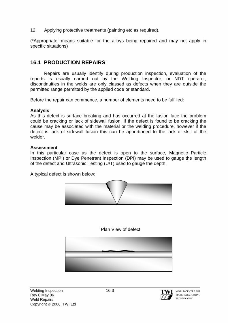
12. Applying protective treatments (painting etc as required).
(*Appropriate’ means suitable for the alloys being repaired and may not apply in specific situations) 16.1 PRODUCTION REPAIRS:
Repairs are usually identify during production inspection, evaluation of the
reports is usually carried out by the Welding Inspector, or NDT operator, discontinuities in the welds are only classed as defects when they are outside the permitted range permitted by the applied code or standard. Before the repair can commence, a number of elements need to be fulfilled: Analysis As this defect is surface breaking and has occurred at the fusion face the problem could be cracking or lack of sidewall fusion. If the defect is found to be cracking the cause may be associated with the material or the welding procedure, however if the defect is lack of sidewall fusion this can be apportioned to the lack of skill of the welder. Assessment In this particular case as the defect is open to the surface, Magnetic Particle Inspection (MPI) or Dye Penetrant Inspection (DPI) may be used to gauge the length of the defect and Ultrasonic Testing (U/T) used to gauge the depth. A typical defect is shown below:
Plan View of defect
Welding Inspection 16.3 WORLD CENTRE FOR
MATERIALS JOINING TECHNOLOGY
Rev 0 May 06 Weld Repairs Copyright © 2006, TWI Ltd

Excavation If a thermal method of excavation is being used i.e. Arc-Air gouging it may be a requirement to qualify a procedure as the heat generated may have an affect on the metallurgical structure, resulting in the risk of cracking in the weld or parent material
To prevent cracking it may be necessary to apply a preheat. The depth to width ratio shall not be less than 1 (depth) to 1 (width) ideally 1 to 1.5 would be recommended (ratio: depth 1 to the width 1.5)
Side View of excavation for slight sub surface defect
Welding Inspection 16.4 Rev 0 May 06 Weld Repairs Copyright © 2006, TWI Ltd
WORLD CENTRE FOR MATERIALS JOINING TECHNOLOGY
D
W
Side View of excavation for deep defect
D
W
Side View of excavation for full root repair
D
W

Cleaning of the excavation At this stage grinding of the repair area is important, due to the risk of carbon becoming impregnated into the weld metal/parent material. It should be ground back typically 3 to 4 mm to bright metal.
Confirmation of excavation At this stage NDT should be used to confirm that the defect has been completely excavated from the area.
Welding Inspection 16.5 WORLD CENTRE FOR MATERIALS JOINING TECHNOLOGY
Rev 0 May 06 Weld Repairs Copyright © 2006, TWI Ltd

Re-welding of the excavation Prior to re-welding of the excavation a detailed repair welding procedure/method statement shall be approved.
Typical side view of weld repair
NDT confirmation of successful repair After the excavation has been filled the weldment should then undergo a complete retest using the same NDT techniques as previously used to establish the original repair, this is carried out to ensure no further defects have been introduced by the repair welding process. NDT may also need to be further applied after any additional post weld heat treatment has been carried out. 16.2 IN SERVICE REPAIRS
Most in service repairs can be of a very complex nature, as the component is very likely to be in a different welding position and condition than it was during production. It may also have been in contact with toxic or combustible fluids hence a permit to work will need to be sought prior to any work being carried out. The repair welding procedure may look very different to the original production procedure due to changes in these elements.
Other factors may also be taken into consideration, such as the effect of heat on any surrounding areas of the component i.e. electrical components, or materials that may become damaged by the repair procedure. This may also include difficulty in carrying out any required pre or post welding heat treatments and a possible restriction of access to the area to be repaired. For large fabrications it is likely that the repair must also take place on site and without a shut down of operations, which may bring other elements that need to be considered.
Repair of in service defects may require consideration of these and many other factors, and as such are generally considered more complicated than production repairs.
Welding Inspection 16.6 WORLD CENTRE FOR MATERIALS JOINING TECHNOLOGY
Rev 0 May 06 Weld Repairs Copyright © 2006, TWI Ltd

Welding Inspection 16.7 Rev 0 May 06 Weld Repairs Copyright © 2006, TWI Ltd
WORLD CENTRE FOR MATERIALS JOINING TECHNOLOGY
Joining technologies often play a vital role in the repair and maintenance of structures. Parts can be replaced, worn or corroded parts can be built up, and cracks can be repaired.
When a repair is required it is important to determine two things: firstly, the reason for failure and, secondly, can the component actually be repaired? The latter point infers that the material type is known. For metals, particularly those to be welded, the chemical composition is vitally important. Failure modes often indicate the approach required to make a sound repair. When the cause-effect analysis, however simple, is not followed through it is often the case that the repair is unsafe - sometimes disastrously so.
In many instances, the Standard or Code used to design the structure will define the type of repair that can be carried out and will also give guidance on the methods to be followed. Standards imply that when designing or manufacturing a new product it is important to consider a maintenance regime and repair procedures. Repairs may be required during manufacture and this situation should also be considered.
Normally, there is more than one way of making a repair. For example, cracks in cast iron might be held together or repaired by: pinning, bolting, riveting, welding, or brazing. The method chosen will depend on factors such as the reason for the failure, the material composition and cleanliness, the environment and the size and shape of the component.
It is very important that repair and maintenance welding are not regarded as
activities, which are simple or straightforward. In many instances a repair may seem undemanding but the consequences of getting it wrong can be catastrophic failure with disastrous consequences. Is welding the best method of repair? If repair is called for because a component has a local irregularity or a shallow defect, grinding out any defects and blending to a smooth contour might well be acceptable. It will certainly be preferable if the steel has poor weldability or if fatigue loading is severe. It is often better to reduce the so-called factor of safety slightly, than to risk putting defects, stress concentrations and residual stresses into a brittle material. In fact brittle materials - which can include some steels (particularly in thick sections) as well as cast irons - may not be able to withstand the residual stresses imposed by heavy weld repairs, particularly if defects are not all removed, leaving stress concentrations to initiate cracking. Is the repair really like earlier repairs? Repairs of one sort may have been routine for many years. It is important, however, to check that the next one is not subtly different. For example, the section thickness may be greater; the steel to be repaired may be different and less Weldable, or the restraint higher. If there is any doubt, answer the remaining questions.

Welding Inspection 16.8 Rev 0 May 06 Weld Repairs Copyright © 2006, TWI Ltd
WORLD CENTRE FOR MATERIALS JOINING TECHNOLOGY
What is the composition and weldability of the base metal? The original drawings will usually give some idea of the steel involved, although the specification limits may then have been less stringent, and the specification may not give enough compositional details to be helpful. If sulphur-bearing free-machining steel is involved, it could give hot cracking problems during welding. If there is any doubt about the composition, a chemical analysis should be carried out. It is important to analyse for all elements, which may affect weldability (Ni, Cr, Mo, Cu, V, Nb and B) as well as those usually, specified (C, S, P, Si and Mn). A small cost spent on analysis could prevent a valuable component being ruined by ill-prepared repairs or, save money by reducing or avoiding the need for preheat if the composition were leaner than expected. Once the composition is known, a welding procedure can be devised What strength is required from the repair? The higher the yield strength of the repair weld metal, the greater will be the residual stress level on completion of welding, the greater the risk of cracking, the greater the clamping needed to avoid distortion and more difficulty in formulating the welding procedure. In any case, the practical limit for the yield strength of conventional steel weld metals is about 1000 N/mm2. Can preheat be tolerated? Not only does a high level of preheat make conditions more difficult for the welder; the parent steel can be damaged if it has been tempered at a low temperature. In other cases the steel being repaired may contain items, which are damaged by excessive heating. Preheat levels can be reduced by using consumables of ultra-low hydrogen content or by non-Ferritic weld metals. Of these, austenitic electrodes may need some preheat, but the more expensive nickel alloys usually do not. However, the latter may be sensitive to high sulphur and phosphorus contents in the parent steel if diluted into the weld metal. Can softening or hardening of the Heat Affected Zone (HAZ) be tolerated? Softening of the HAZ (heat affected zone) is likely in very high strength steels, particularly if they have been tempered at low temperatures. Such softening cannot be avoided, but its extent can be minimised. Hard HAZ’s are particularly vulnerable where service conditions can lead to stress corrosion. Solutions containing H2S (hydrogen sulphide) may demand hardness’ below 248 HV (22 HRC) although fresh aerated seawater appears to tolerate up to about 450 HV. Excessively hard HAZ’s may, therefore, require Post Weld Heat Treatment (PWHT) to soften them but provided cracking has been avoided. Is PWHT practicable? Although it may be desirable, PWHT may not be possible for the same reasons that preheating is not possible. For large structures, local PWHT may be possible, but care should be taken to abide by the relevant codes, because it is all too easy to introduce new residual stresses by improperly executed PWHT.
Welding Inspection 16.9 Rev 0 May 06 Weld Repairs Copyright © 2006, TWI Ltd
WORLD CENTRE FOR MATERIALS JOINING TECHNOLOGY
Is PWHT necessary? PWHT may be needed for one of several reasons, and the reason must be known before considering whether it can be avoided. Will the fatigue resistance of the repair be adequate? If the repair is in an area, which is highly stressed by fatigue, and particularly if the attempted repair is of a fatigue crack, inferior fatigue life can be expected unless the weld surface is ground smooth and no surface defects are left. Fillet welds, in which the root cannot be ground smooth, are not tolerable in areas of high fatigue stress. Will the repair resist its environment? Besides corrosion, it is important to consider the possibility of stress corrosion, corrosion fatigue, thermal fatigue and oxidation in service. Corrosion and oxidation resistance usually requires that the composition of the filler metal is at least as noble or oxidation resistant as the parent metal. For corrosion fatigue resistance, the repair weld profile may need to be smoothed. To resist stress corrosion, PWHT may be necessary to restore the correct microstructure, reduce hardness and reduce the residual stress left by the repair. Can the repair be inspected and tested? For onerous service, radiography and/or ultrasonic examination are often desirable, but problems are likely if stainless steel or nickel alloy filler is used; moreover, such repairs cannot be assessed by magnetic particle inspection. In such cases, it is particularly important to carry out the procedural tests for repairs very critically, to ensure that there are no risks of cracking and no likelihood of serious welder-induced defects. Indeed, for all repair welds, it is vital to ensure that the welders are properly motivated and carefully supervised. As-welded repairs Repair without PWHT is, of course, normal where the original weld was not heat treated, but some alloy steels and many thick-sectioned components require PWHT to maintain a reasonable level of toughness, corrosion resistance etc. However, PWHT of components in service is not always easy or even possible, and local PWHT may give rise to more problems than it solves except in simple structures.
Welding Inspection Rev 0 Jun 06 Copyright © 2006, TWI Ltd
WORLD CENTRE FOR MATERIALS JOINING TECHNOLOGY
Section 17
Residual Stress and Distortion
Welding Inspection 17.1 Rev 0 Jun 06 Residual Stress & Distortion Copyright © 2006, TWI Ltd
WORLD CENTRE FOR MATERIALS JOINING TECHNOLOGY
17.0 RESIDUAL STRESS AND DISTORTION 17.1 WHAT CAUSES DISTORTION? Because welding involves highly localised heating of joint edges to fuse the material, non-uniform stresses are set up in the component because of expansion and contraction of the heated material. Initially, compressive stresses are created in the surrounding cold parent metal when the weld pool is formed due to the thermal expansion of the hot metal (heat affected zone) adjacent to the weld pool. However, tensile stresses occur on cooling when the contraction of the weld metal and immediate heat affected zone is resisted by the bulk of the cold parent metal. The magnitude of thermal stresses induced into the material can be seen by the volume change in the weld area on solidification and subsequent cooling to room temperature. For example, when welding C-Mn steel, the molten weld metal volume will be reduced by approximately 3% on solidification and the volume of the solidified weld metal/heat affected zone will be reduced by a further 7% as its temperature falls from the melting point of steel to room temperature. If the stresses generated from thermal expansion/contraction exceed the yield strength of the parent metal, localised plastic deformation of the metal occurs. Plastic deformation causes a permanent reduction in the component dimensions and distorts the structure. 17.2 WHAT ARE THE MAIN TYPES OF DISTORTION? Distortion occurs in several ways: • Longitudinal shrinkage
• Transverse shrinkage
• Angular distortion
• Bowing and dishing
• Buckling Contraction of the weld area on cooling results in both transverse and longitudinal shrinkage. Non-uniform contraction (through thickness) produces angular distortion as well as longitudinal and transverse shrinking.

For example, in a single V butt weld, the first weld run produces longitudinal and transverse shrinkage and rotation. The second run causes the plates to rotate using the first weld deposit as a fulcrum. Therefore balanced welding in a double side V butt joint can be used to produce uniform contraction and prevent angular distortion. Similarly, in a single sided fillet weld, non-uniform contraction will produce angular distortion of the upstanding leg. Double-sided fillet welds can therefore be used to control distortion in the upstanding fillet but because the weld is only deposited on one side of the base plate, angular distortion will now be produced in the plate. Longitudinal bowing in welded plates happens when the weld centre is not coincident with the neutral axis of the section so that longitudinal shrinkage in the welds bends the section into a curved shape. Clad plate tends to bow in two directions due to longitudinal and transverse shrinkage of the cladding. This produces a dished shape. Dishing is also produced in stiffened plating. Plates usually dish inwards between the stiffeners, because of angular distortion at the stiffener attachment welds. In plating, long range compressive stresses can cause elastic buckling in thin plates, resulting in dishing, bowing or rippling. (see Figure below)
Examples of distortion Increasing the leg length of fillet welds, in particular, increases shrinkage. 17.3 WHAT ARE THE FACTORS AFFECTING DISTORTION? If a metal is uniformly heated and cooled there would be almost no distortion. However, because the material is locally heated and restrained by the surrounding cold metal, stresses are generated higher than the material yield stress causing permanent distortion. The principal factors affecting the type and degree of distortion are:
Welding Inspection 17.2 WORLD CENTRE FOR MATERIALS JOINING TECHNOLOGY
Rev 0 Jun 06 Residual Stress & Distortion Copyright © 2006, TWI Ltd
Welding Inspection 17.3 Rev 0 Jun 06 Residual Stress & Distortion Copyright © 2006, TWI Ltd
WORLD CENTRE FOR MATERIALS JOINING TECHNOLOGY
• Parent material properties
• Amount of restraint
• Joint design
• Part fit-up
• Welding procedure 17.3.1 PARENT MATERIAL PROPERTIES Parent material properties, which influence distortion, are coefficient of thermal expansion and specific heat per unit volume. As distortion is determined by expansion and contraction of the material, the coefficient of thermal expansion of the material plays a significant role in determining the stresses generated during welding and, hence, the degree of distortion. For example, as stainless steel has a higher coefficient of expansion than plain carbon steel, it is more likely to suffer from distortion. 17.3.2 RESTRAINT If a component is welded without any external restraint, it distorts to relieve the welding stresses. So, methods of restraint, such as 'strong-backs' in butt welds, can prevent movement and reduce distortion. As restraint produces higher levels of residual stress in the material, there is a greater risk of cracking in weld metal and HAZ especially in crack-sensitive materials. 17.3.3 JOINT DESIGN Both butt and fillet joints are prone to distortion. It can be minimised in butt joints by adopting a joint type, which balances the thermal stresses through the plate thickness. For example, a double-sided in preference to a single-sided weld. Double-sided fillet welds should eliminate angular distortion of the upstanding member, especially if the two welds are deposited at the same time. 17.3.4 PART FIT-UP Fit-up should be uniform to produce predictable and consistent shrinkage. Excessive joint gap can also increase the degree of distortion by increasing the amount of weld metal needed to fill the joint. The joints should be adequately tacked to prevent relative movement between the parts during welding.

17.3.5 WELDING PROCEDURE This influences the degree of distortion mainly through its effect on the heat input. As welding procedures are usually selected for reasons of quality and productivity, the welder has limited scope for reducing distortion. As a general rule, weld volume should be kept to a minimum. Also, the welding sequence and technique should aim to balance the thermally induced stresses around the neutral axis of the component. 17.4 DISTORTION - PREVENTION BY PRE-SETTING, PRE-BENDING OR USE OF RESTRAINT Distortion could often be prevented at the design stage, for example, by placing the welds about the neutral axis, reducing the amount of welding and depositing the weld metal using a balanced welding technique. In designs where this is not possible, distortion may be prevented by one of the following methods: • pre-setting of parts
• pre-bending of parts
• use of restraint The technique chosen will be influenced by the size and complexity of the component or assembly, the cost of any restraining equipment and the need to limit residual stresses.
Pre-setting of parts to produce correct alignment after welding
a) Pre-setting of fillet joint to prevent angular distortion b) Pre-setting of butt joint to prevent angular distortion
17.4.1 PRE-SETTING OF PARTS The parts are pre-set and left free to move during welding (see figure above). In practice, the parts are pre-set by a pre-determined amount so that distortion occurring during welding is used to achieve overall alignment and dimensional control.
Welding Inspection 17.4 WORLD CENTRE FOR MATERIALS JOINING TECHNOLOGY
Rev 0 Jun 06 Residual Stress & Distortion Copyright © 2006, TWI Ltd
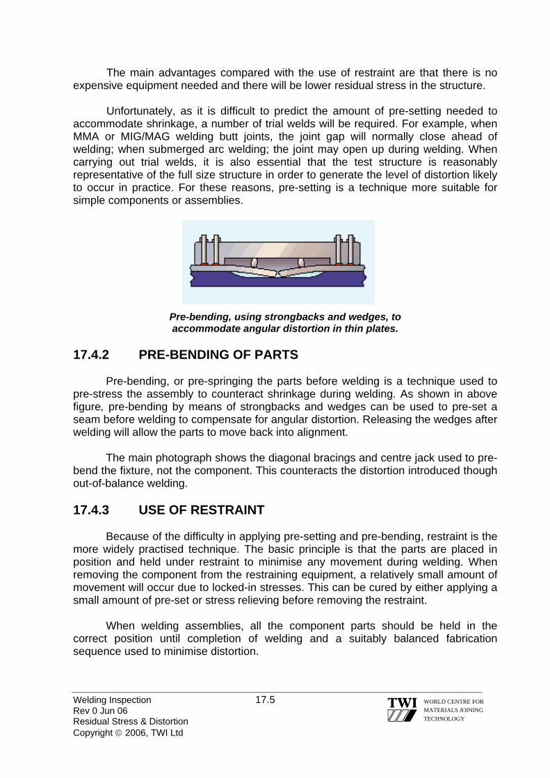
The main advantages compared with the use of restraint are that there is no expensive equipment needed and there will be lower residual stress in the structure.
Unfortunately, as it is difficult to predict the amount of pre-setting needed to accommodate shrinkage, a number of trial welds will be required. For example, when MMA or MIG/MAG welding butt joints, the joint gap will normally close ahead of welding; when submerged arc welding; the joint may open up during welding. When carrying out trial welds, it is also essential that the test structure is reasonably representative of the full size structure in order to generate the level of distortion likely to occur in practice. For these reasons, pre-setting is a technique more suitable for simple components or assemblies.
Pre-bending, using strongbacks and wedges, to accommodate angular distortion in thin plates.
17.4.2 PRE-BENDING OF PARTS Pre-bending, or pre-springing the parts before welding is a technique used to pre-stress the assembly to counteract shrinkage during welding. As shown in above figure, pre-bending by means of strongbacks and wedges can be used to pre-set a seam before welding to compensate for angular distortion. Releasing the wedges after welding will allow the parts to move back into alignment. The main photograph shows the diagonal bracings and centre jack used to pre-bend the fixture, not the component. This counteracts the distortion introduced though out-of-balance welding. 17.4.3 USE OF RESTRAINT Because of the difficulty in applying pre-setting and pre-bending, restraint is the more widely practised technique. The basic principle is that the parts are placed in position and held under restraint to minimise any movement during welding. When removing the component from the restraining equipment, a relatively small amount of movement will occur due to locked-in stresses. This can be cured by either applying a small amount of pre-set or stress relieving before removing the restraint. When welding assemblies, all the component parts should be held in the correct position until completion of welding and a suitably balanced fabrication sequence used to minimise distortion.
Welding Inspection 17.5 WORLD CENTRE FOR MATERIALS JOINING TECHNOLOGY
Rev 0 Jun 06 Residual Stress & Distortion Copyright © 2006, TWI Ltd

Welding with restraint will generate additional residual stresses in the weld, which may cause cracking. When welding susceptible materials, a suitable welding sequence and the use of preheating will reduce this risk. Restraint is relatively simple to apply using clamps, jigs and fixtures to hold the parts during welding. 17.4.3.1 WELDING JIGS AND FIXTURES
Jigs and fixtures are used to locate the parts and to ensure that dimensional accuracy is maintained whilst welding. They can be of a relatively simple construction, as shown in figure a below but the welding engineer will need to ensure that the finished fabrication can be removed easily after welding. 17.4.3.2 FLEXIBLE CLAMPS A flexible clamp (Fig b below) can be effective not only in applying restraint but also in setting up and maintaining the joint gap (it can also be used to close a gap that is too wide).
A disadvantage is that as the restraining forces in the clamp will be transferred into the joint when the clamps are removed, the level of residual stress across the joint can be quite high.
a) Welding jig
b) Flexible clamps
c) Strongbacks with wedges
d) Fully welded strongbacks
Restraint techniques to prevent distortion
Welding Inspection 17.6 WORLD CENTRE FOR MATERIALS JOINING TECHNOLOGY
Rev 0 Jun 06 Residual Stress & Distortion Copyright © 2006, TWI Ltd

Welding Inspection 17.7 Rev 0 Jun 06 Residual Stress & Distortion Copyright © 2006, TWI Ltd
WORLD CENTRE FOR MATERIALS JOINING TECHNOLOGY
17.4.3.3 STRONGBACKS (AND WEDGES) Strongbacks are a popular means of applying restraint especially for site work. Wedged strongbacks (Fig.c above), will prevent angular distortion in plate and help to prevent peaking in welding cylindrical shells. As these types of strongback will allow transverse shrinkage, the risk of cracking will be greatly reduced compared with fully welded strongbacks. Fully welded strongbacks (welded on both sides of the joint) (Fig d above) will minimise both angular distortion and transverse shrinkage. As significant stresses can be generated across the weld, which will increase any tendency for cracking, care should be taken in the use of this type of strongback. 17.4.4 BEST PRACTICE Adopting the following assembly techniques will help to control distortion: • Pre-set parts so that welding distortion will achieve overall alignment and
dimensional control with the minimum of residual stress
• Pre-bend joint edges to counteract distortion and achieve alignment and dimensional control with minimum residual stress.
• Apply restraint during welding by using jigs and fixtures, flexible clamps, strongbacks and tack welding but consider the risk of cracking which can be quite significant, especially for fully welded strongbacks.
• Use an approved procedure for welding and removal of welds for restraint techniques, which may need preheat to avoid forming imperfections in the component surface.
17.5 DISTORTION - PREVENTION BY DESIGN Design principles At the design stage, welding distortion can often be prevented, or at least restricted, by considering: • elimination of welding
• weld placement
• reducing the volume of weld metal
• reducing the number of runs
• use of balanced welding

17.5.1 ELIMINATION OF WELDING As distortion and shrinkage are an inevitable result of welding, good design requires that not only the amount of welding is kept to a minimum, but also the smallest amount of weld metal is deposited. Welding can often be eliminated at the design stage by forming the plate or using a standard rolled section, as shown in this figure.
Elimination of welds by: a) forming the plate; b) use of rolled or extruded section
If possible, the design should use intermittent welds rather than a continuous run, to reduce the amount of welding. For example, in attaching stiffening plates, a substantial reduction in the amount of welding can often be achieved whilst maintaining adequate strength. 17.5.2 WELD PLACEMENT Placing and balancing of welds are important in designing for minimum distortion. The closer a weld is positioned to the neutral axis of a fabrication, the lower the leverage effect of the shrinkage forces and the final distortion. Examples of poor and good designs are shown in the figure below.
Distortion may be reduced by placing the welds around the neutral axis
As most welds are deposited away from the neutral axis, distortion can be minimised by designing the fabrication so the shrinkage forces of an individual weld are balanced by placing another weld on the opposite side of the neutral axis. Whenever possible, welding should be carried out alternately on opposite sides, instead of completing one side first. In large structures, if distortion is occurring preferentially on one side, it may be possible to take corrective actions, for example, by increasing welding on the other side to control the overall distortion.
Welding Inspection 17.8 WORLD CENTRE FOR MATERIALS JOINING TECHNOLOGY
Rev 0 Jun 06 Residual Stress & Distortion Copyright © 2006, TWI Ltd

17.5.3 REDUCING THE VOLUME OF WELD METAL To minimise distortion, as well as for economic reasons, the volume of weld metal should be limited to the design requirements. For a single-sided joint, the cross-section of the weld should be kept as small as possible to reduce the level of angular distortion, as illustrated in below figure.
Reducing the amount of angular distortion and lateral shrinkage Ways of reducing angular distortion and lateral shrinkage a) reducing the volume of weld metal; b) using single pass weld Joint preparation angle and root gap should be minimised providing the weld can be made satisfactorily. To facilitate access, it may be possible to specify a larger root gap and smaller preparation angle. By cutting down the difference in the amount of weld metal at the root and the face of the weld, the degree of angular distortion will be correspondingly reduced. Butt joints made in a single pass using deep penetration have little angular distortion, especially if a closed butt joint can be welded (Figure above). For example, thin section material can be welded using plasma and laser welding processes and thick section can be welded, in the vertical position, using electrogas and electroslag processes. Although angular distortion can be eliminated, there will still be longitudinal and transverse shrinkage. In thick section material, as the cross sectional area of a double-V joint preparation is often only half that of a single-V preparation, the volume of weld metal to be deposited can be substantially reduced. The double-V joint preparation also permits balanced welding about the middle of the joint to eliminate angular distortion. As weld shrinkage is proportional to the amount of weld metal both poor joint fit-up and over-welding will increase the amount of distortion. Angular distortion in fillet welds is particularly affected by over-welding. As design strength is based on throat thickness, over-welding to produce a convex weld bead does not increase the allowable design strength but it will increase the shrinkage and distortion.
Welding Inspection 17.9 WORLD CENTRE FOR MATERIALS JOINING TECHNOLOGY
Rev 0 Jun 06 Residual Stress & Distortion Copyright © 2006, TWI Ltd

17.5.4 REDUCING THE NUMBER OF RUNS There are conflicting opinions on whether it is better to deposit a given volume of weld metal using a small number of large weld passes or a large number of small passes. Experience shows that for a single-sided butt joint, or a single-side fillet weld, a large single weld deposit gives less angular distortion than if the weld is made with a number of small runs. Generally, in an unrestrained joint, the degree of angular distortion is approximately proportional to the number of passes. Completing the joint with a small number of large weld deposits results in more longitudinal and transverse shrinkage than a weld completed in a larger number of small passes. In a multi-pass weld, previously deposited weld metal provides restraint, so the angular distortion per pass decreases as the weld is built up. Large deposits also increase the risk of elastic buckling particularly in thin section plate. 17.5.5 USE OF BALANCED WELDING Balanced welding is an effective means of controlling angular distortion in a multi-pass butt weld by arranging the welding sequence to ensure that angular distortion is continually being corrected and not allowed to accumulate during welding. Comparative amounts of angular distortion from balanced welding and welding one side of the joint first are shown schematically in this figure. The balanced welding technique can also be applied to fillet joints.
Balanced welding to reduce the amount of angular distortion If welding alternately on either side of the joint is not possible, or if one side has to be completed first, an asymmetrical joint preparation may be used with more weld metal being deposited on the second side. The greater contraction resulting from depositing the weld metal on the second side will help counteract the distortion on the first side.
Welding Inspection 17.10 WORLD CENTRE FOR MATERIALS JOINING TECHNOLOGY
Rev 0 Jun 06 Residual Stress & Distortion Copyright © 2006, TWI Ltd

Welding Inspection 17.11 Rev 0 Jun 06 Residual Stress & Distortion Copyright © 2006, TWI Ltd
WORLD CENTRE FOR MATERIALS JOINING TECHNOLOGY
17.5.6 BEST PRACTICE The following design principles can control distortion: • eliminate welding by forming the plate and using rolled or extruded sections
• minimise the amount of weld metal
• do not over weld
• use intermittent welding in preference to a continuous weld pass
• place welds about the neutral axis
• balance the welding about the middle of the joint by using a double-V joint in preference to a single-V joint
Adopting best practice principles can have surprising cost benefits. For example, for a design fillet leg length of 6mm, depositing an 8mm-leg length will result in the deposition of 57% additional weld metal. Besides the extra cost of depositing weld metal and the increase risk of distortion, it is costly to remove this extra weld metal later. However, designing for distortion control may incur additional fabrication costs. For example, the use of a double-V joint preparation is an excellent way to reduce weld volume and control distortion, but extra costs may be incurred in production through manipulation of the workpiece for the welder to access the reverse side. 17.6 DISTORTION - PREVENTION BY FABRICATION TECHNIQUES 17.6.1 ASSEMBLY TECHNIQUES In general, the welder has little influence on the choice of welding procedure but assembly techniques can often be crucial in minimising distortion. The principal assembly techniques are: • tack welding
• back-to-back assembly
• stiffening
17.6.1.1 TACK WELDING Tack welds are ideal for setting and maintaining the joint gap but can also be used to resist transverse shrinkage. To be effective, thought should be given to the number of tack welds, their length and the distance between them. With too few, there is the risk of the joint progressively closing up as welding proceeds. In a long seam,

using MMA or MIG/MAG, the joint edges may even overlap. It should be noted that when using the submerged arc process, the joint might open up if not adequately tacked. The tack welding sequence is important to maintain a uniform root gap along the length of the joint. Three alternative tack-welding sequences are shown in the figure below: • tack weld straight through to the end of the joint (figure a). It is necessary to
clamp the plates or to use wedges to maintain the joint gap during tacking
• tack weld one end and then use a back stepping technique for tacking the rest of the joint (figure b)
• tack weld the centre and complete the tack welding by back stepping (figure c).
Alternative procedures used for tack welding to prevent transverse shrinkage Directional tacking is a useful technique for controlling the joint gap, for example closing a joint gap which is (or has become) too wide. When tack welding, it is important that tacks which are to be fused into the main weld, are produced to an approved procedure using appropriately qualified welders. The procedure may require preheat and an approved consumable as specified for the main weld. Removal of the tacks also needs careful control to avoid causing defects in the component surface. 17.6.1.2 BACK-TO-BACK ASSEMBLY By tack welding or clamping two identical components back-to-back, welding of both components can be balanced around the neutral axis of the combined assembly (see figure a on next page). It is recommended that the assembly is stress relieved before separating the components. If stress relieving is not done, it may be necessary to insert wedges between the components (figure b on next page) so when the wedges are removed, the parts will move back to the correct shape or alignment.
Welding Inspection 17.12 WORLD CENTRE FOR MATERIALS JOINING TECHNOLOGY
Rev 0 Jun 06 Residual Stress & Distortion Copyright © 2006, TWI Ltd

a) assemblies tacked together before welding b) use of wedges for components that distort on separation after welding
Back-to-back assembly to control distortion when welding two identical components 17.6.1.3 STIFFENING
Welding Inspection 17.13 Rev 0 Jun 06 Residual Stress & Distortion Copyright © 2006, TWI Ltd
WORLD CENTRE FOR MATERIALS JOINING TECHNOLOGY
Longitudinal stiffeners prevent bowing in butt welded thin plate joints
Longitudinal shrinkage in butt-welded seams often results in bowing, especially when fabricating thin plate structures. Longitudinal stiffeners in the form of flats or angles, welded along each side of the seam (Fig just above) are effective in preventing longitudinal bowing. Stiffener location is important: they must be placed at a sufficient distance from the joint so they do not interfere with welding, unless located on the reverse side of a joint welded from one side. 17.6.2 WELDING PROCEDURE A suitable welding procedure is usually determined by productivity and quality requirements rather than the need to control distortion. Nevertheless, the welding process, technique and sequence do influence the distortion level. Welding Process General rules for selecting a welding process to prevent angular distortion are: • deposit the weld metal as quickly as possible
• use the least number of runs to fill the joint
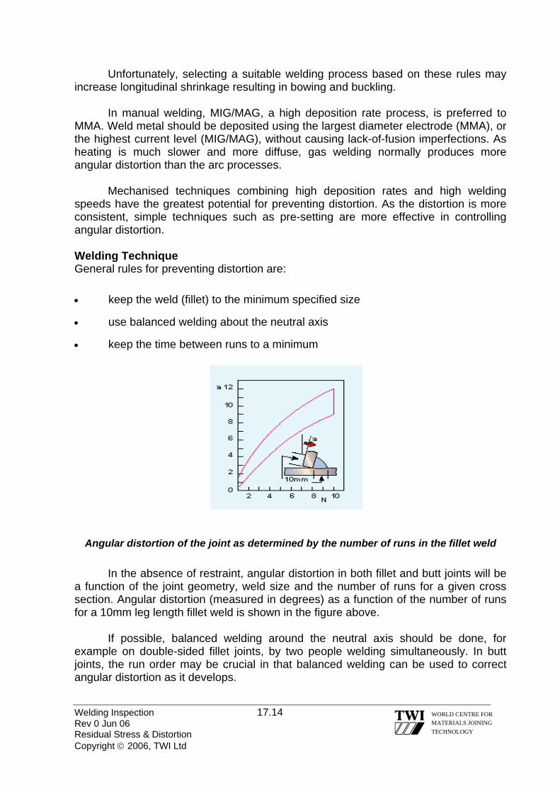
Unfortunately, selecting a suitable welding process based on these rules may increase longitudinal shrinkage resulting in bowing and buckling. In manual welding, MIG/MAG, a high deposition rate process, is preferred to MMA. Weld metal should be deposited using the largest diameter electrode (MMA), or the highest current level (MIG/MAG), without causing lack-of-fusion imperfections. As heating is much slower and more diffuse, gas welding normally produces more angular distortion than the arc processes. Mechanised techniques combining high deposition rates and high welding speeds have the greatest potential for preventing distortion. As the distortion is more consistent, simple techniques such as pre-setting are more effective in controlling angular distortion. Welding Technique General rules for preventing distortion are: • keep the weld (fillet) to the minimum specified size
• use balanced welding about the neutral axis
• keep the time between runs to a minimum
Angular distortion of the joint as determined by the number of runs in the fillet weld In the absence of restraint, angular distortion in both fillet and butt joints will be a function of the joint geometry, weld size and the number of runs for a given cross section. Angular distortion (measured in degrees) as a function of the number of runs for a 10mm leg length fillet weld is shown in the figure above. If possible, balanced welding around the neutral axis should be done, for example on double-sided fillet joints, by two people welding simultaneously. In butt joints, the run order may be crucial in that balanced welding can be used to correct angular distortion as it develops.
Welding Inspection 17.14 WORLD CENTRE FOR MATERIALS JOINING TECHNOLOGY
Rev 0 Jun 06 Residual Stress & Distortion Copyright © 2006, TWI Ltd

a) Back-step welding b) Skip welding
Use of welding direction to control distortion Welding Sequence The welding sequence, or direction, of welding is important and should be towards the free end of the joint. For long welds, the whole of the weld is not completed in one direction. Short runs, for example using the back-step or skip welding technique, are very effective in distortion control (figure just above • Back-step welding involves depositing short adjacent weld lengths in the
opposite direction to the general progression (a in above figure
• Skip welding is laying short weld lengths in a predetermined, evenly spaced, sequence along the seam (b in above figure). Weld lengths and the spaces between them are generally equal to the natural run-out length of one electrode. The direction of deposit for each electrode is the same, but it is not necessary for the welding direction to be opposite to the direction of general progression.
17.6.3 BEST PRACTICE The following fabrication techniques are used to control distortion: • using tack welds to set up and maintain the joint gap
• identical components welded back to back so welding can be balanced about the neutral axis
• attachment of longitudinal stiffeners to prevent longitudinal bowing in butt welds of thin plate structures
• where there is choice of welding procedure, process and technique should aim to deposit the weld metal as quickly as possible; MIG/MAG in preference to MMA or gas welding and mechanised rather than manual welding
• in long runs, the whole weld should not be completed in one direction; back-step or skip welding techniques should be used.
Welding Inspection 17.15 WORLD CENTRE FOR MATERIALS JOINING TECHNOLOGY
Rev 0 Jun 06 Residual Stress & Distortion Copyright © 2006, TWI Ltd

17.7 DISTORTION - CORRECTIVE TECHNIQUES Every effort should be made to avoid distortion at the design stage and by using suitable fabrication procedures. As it is not always possible to avoid distortion during fabrication, several well-established corrective techniques can be employed. However, reworking to correct distortion should not be undertaken lightly as it is costly and needs considerable skill to avoid damaging the component.
In this issue, general guidelines are provided on 'best practice' for correcting distortion using mechanical or thermal techniques. 17.7.1 MECHANICAL TECHNIQUES The principal mechanical techniques are hammering and pressing. Hammering may cause surface damage and work hardening. In cases of bowing or angular distortion, the complete component can often be straightened on a press without the disadvantages of hammering. Packing pieces are inserted between the component and the platens of the press. It is important to impose sufficient deformation to give over-correction so that the normal elastic spring-back will allow the component to assume its correct shape.
Use of press to correct bowing in T butt joint
Pressing to correct bowing in a flanged plate is illustrated in Fig. 14. In long components, distortion is removed progressively in a series of incremental pressings; each one acting over a short length. In the case of the flanged plate, the load should act on the flange to prevent local damage to the web at the load points. As incremental point loading will only produce an approximately straight component, it is better to use a former to achieve a straight component or to produce a smooth curvature.
Welding Inspection 17.16 WORLD CENTRE FOR MATERIALS JOINING TECHNOLOGY
Rev 0 Jun 06 Residual Stress & Distortion Copyright © 2006, TWI Ltd

17.7.1.1 BEST PRACTICE FOR MECHANICAL STRAIGHTENING The following should be adopted when using pressing techniques to remove distortion: • Use packing pieces which will over correct the distortion so that spring-back will
return the component to the correct shape • Check that the component is adequately supported during pressing to prevent
buckling • Use a former (or rolling) to achieve a straight component or produce a
curvature • As unsecured packing pieces may fly out from the press, the following safe
practice must be adopted: - bolt the packing pieces to the platen - place a metal plate of adequate thickness to intercept the 'missile' - clear personnel from the hazard area
17.7.2 THERMAL TECHNIQUES The basic principle behind thermal techniques is to create sufficiently high local stresses so that, on cooling, the component is pulled back into shape.
Localised heating to correct distortion This is achieved by locally heating the material to a temperature where plastic deformation will occur as the hot, low yield strength material tries to expand against the surrounding cold, higher yield strength metal. On cooling to room temperature the heated area will attempt to shrink to a smaller size than before heating. The stresses generated thereby will pull the component into the required shape. (See figure above) Local heating is, therefore, a relatively simple but effective means of correcting welding distortion. Shrinkage level is determined by size, number, location and temperature of the heated zones. Thickness and plate size determines the area of the heated zone. Number and placement of heating zones are largely a question of experience. For new jobs, tests will often be needed to quantify the level of shrinkage. Spot, line, or wedge-shaped heating techniques can all be used in thermal correction of distortion.
Welding Inspection 17.17 WORLD CENTRE FOR MATERIALS JOINING TECHNOLOGY
Rev 0 Jun 06 Residual Stress & Distortion Copyright © 2006, TWI Ltd

17.7.2.1 SPOT HEATING
Spot heating for correcting buckling Spot heating (figure above), is used to remove buckling, for example when a relatively thin sheet has been welded to a stiff frame. Distortion is corrected by spot heating on the convex side. If the buckling is regular, the spots can be arranged symmetrically, starting at the centre of the buckle and working outwards. 17.7.2.2 LINE HEATING
Line heating to correct angular distortion in a fillet weld
Heating in straight lines is often used to correct angular distortion, for example, in fillet welds (above figure). The component is heated along the line of the welded joint but on the opposite side to the weld so the induced stresses will pull the flange flat. 17.7.2.3 WEDGE-SHAPED HEATING To correct distortion in larger complex fabrications it may be necessary to heat whole areas in addition to employing line heating. The pattern aims at shrinking one part of the fabrication to pull the material back into shape.
Welding Inspection 17.18 WORLD CENTRE FOR MATERIALS JOINING TECHNOLOGY
Rev 0 Jun 06 Residual Stress & Distortion Copyright © 2006, TWI Ltd

Use of wedge shaped heating to straighten plate Apart from spot heating of thin panels, a wedge-shaped heating zone should be used, (figure above) from base to apex and the temperature profile should be uniform through the plate thickness. For thicker section material, it may be necessary to use two torches, one on each side of the plate.
As a general guideline, to straighten a curved plate (Fig. 18) wedge dimensions should be: 1. Length of wedge - two-thirds of the plate width
2. Width of wedge (base) - one sixth of its length (base to apex)
The degree of straightening will typically be 5mm in a 3m length of plate. Wedge-shaped heating can be used to correct distortion in a variety of situations, (See following figure): 1. Standard rolled section, which needs correction in two planes, (Fig. a)
2. Buckle at edge of plate as an alternative to rolling (Fig b)
3. Box section fabrication, which is distorted out of plane (Fig. c)
a) Standard rolled steel section
b) Buckled edge of plate c) Box fabrication
Wedge shaped heating to correct distortion
Welding Inspection 17.19 WORLD CENTRE FOR MATERIALS JOINING TECHNOLOGY
Rev 0 Jun 06 Residual Stress & Distortion Copyright © 2006, TWI Ltd
Welding Inspection 17.20 Rev 0 Jun 06 Residual Stress & Distortion Copyright © 2006, TWI Ltd
WORLD CENTRE FOR MATERIALS JOINING TECHNOLOGY
17.7.2.4 GENERAL PRECAUTIONS The dangers of using thermal straightening techniques are the risk of over-shrinking too large an area or causing metallurgical changes by heating to too high a temperature. As a general rule, when correcting distortion in steels the temperature of the area should be restricted to approximately to 60° - 650°C - dull red heat. If the heating is interrupted, or the heat lost, the operator must allow the metal to cool and then begin again. 17.7.2.5 BEST PRACTICE FOR DISTORTION CORRECTION BY THERMAL HEATING The following should be adopted when using thermal techniques to remove distortion: • use spot heating to remove buckling in thin sheet structures
• other than in spot heating of thin panels, use a wedge-shaped heating technique
• use line heating to correct angular distortion in plate
• restrict the area of heating to avoid over-shrinking the component
• limit the temperature to 60° to 650°C (dull red heat) in steels to prevent metallurgical damage
• in wedge heating, heat from the base to the apex of the wedge, penetrate evenly through the plate thickness and maintain an even temperature
.
Welding Inspection Rev 0 Jun 06 Copyright © 2006, TWI Ltd
WORLD CENTRE FOR MATERIALS JOINING TECHNOLOGY
Section 18
Heat Treatment of Steel & Weld Joints
Welding Inspection 18.1 Rev 0 Jun 06 Heat Treatment Copyright © 2006, TWI Ltd
WORLD CENTRE FOR MATERIALS JOINING TECHNOLOGY
18.0 HEAT TREATMENT OF STEEL & WELD JOINTS 18.1 INTRODUCTION The heat treatment given to a particular grade of steel by the steelmaker/supplier should be shown on the material test certificate and may be referred to as the ‘supply condition’. Welding inspectors may need to refer to material test certificates and it is appropriate that they be familiar with the terminology that is used and have some understanding of the principles of some of the most commonly applied heat treatments. Welded joints may need to be subjected to heat treatment after welding (post-weld heat treatment) and the tasks of monitoring the thermal cycle and checking the heat treatment records are often delegated to welding inspectors. 18.2 HEAT TREATMENT OF STEEL The main supply conditions for weldable steels are: as rolled plate is hot rolled to finished size and allowed to air cool; hot rolled the temperature at which rolling finishes may vary from hot finished plate to plate and so strength and toughness properties
vary and are not optimised; applied to relatively thin, lower strength C-steel
TMCP* steel plate given precisely controlled thickness control-rolled reductions during hot rolling within carefully controlled thermo-mechanically rolled temperature ranges; final rolling temperature is also carefully controlled;
applied to relatively thin, high strength low alloy steels (HSLA steels) and for some steels with good toughness at low temperatures, e.g., cryogenic steels * TMCP = Thermo-Mechanical Controlled Processing
normalised after working the steel (rolling or forging) to size, it is
heated to ~900°C and then allowed to cool in air to ambient temperature; this optimises strength and toughness and gives uniform properties from item to item for a particular grade of steel;
applied to C-Mn steels and some low alloy steels
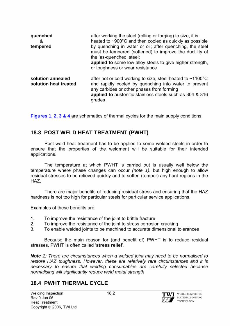
Welding Inspection 18.2 Rev 0 Jun 06 Heat Treatment Copyright © 2006, TWI Ltd
WORLD CENTRE FOR MATERIALS JOINING TECHNOLOGY
quenched after working the steel (rolling or forging) to size, it is & heated to ~900°C and then cooled as quickly as possible tempered by quenching in water or oil; after quenching, the steel
must be tempered (softened) to improve the ductility of the ‘as-quenched’ steel;
applied to some low alloy steels to give higher strength, or toughness or wear resistance
solution annealed after hot or cold working to size, steel heated to ~1100°C solution heat treated and rapidly cooled by quenching into water to prevent
any carbides or other phases from forming applied to austenitic stainless steels such as 304 & 316
grades Figures 1, 2, 3 & 4 are schematics of thermal cycles for the main supply conditions. 18.3 POST WELD HEAT TREATMENT (PWHT)
Post weld heat treatment has to be applied to some welded steels in order to ensure that the properties of the weldment will be suitable for their intended applications.
The temperature at which PWHT is carried out is usually well below the temperature where phase changes can occur (note 1), but high enough to allow residual stresses to be relieved quickly and to soften (temper) any hard regions in the HAZ.
There are major benefits of reducing residual stress and ensuring that the HAZ hardness is not too high for particular steels for particular service applications. Examples of these benefits are: 1. To improve the resistance of the joint to brittle fracture 2. To improve the resistance of the joint to stress corrosion cracking 3. To enable welded joints to be machined to accurate dimensional tolerances Because the main reason for (and benefit of) PWHT is to reduce residual stresses, PWHT is often called ‘stress relief’. Note 1: There are circumstances when a welded joint may need to be normalised to restore HAZ toughness. However, these are relatively rare circumstances and it is necessary to ensure that welding consumables are carefully selected because normalising will significantly reduce weld metal strength 18.4 PWHT THERMAL CYCLE

Welding Inspection 18.3 Rev 0 Jun 06 Heat Treatment Copyright © 2006, TWI Ltd
WORLD CENTRE FOR MATERIALS JOINING TECHNOLOGY
The Application Standard/Code, will specify when PWHT is required to give
benefits #1 or #2 above and also give guidance about the thermal cycle that must be used. In order to ensure that a PWHT cycle is carried it in accordance with a particular Code, it is essential that a PWHT procedure is prepared and that the following parameters are specified: -
• the maximum heating rate
• the soak temperature range
• the minimum time at the soak temperature (soak time)
• the maximum cooling rate 18.4.1 HEATING RATE This must be controlled to avoid large temperature differences within the fabricated item. Large differences in temperature (large thermal gradients) will produce large stresses and these may be high enough to cause distortion (or even cracking).
Application Standards usually require control of the maximum heating rate when the temperature of the item is above ~300°C. This is because steels start to show significant loss of strength above this temperature and are more susceptible to distortion if there are large thermal gradients.
The temperature of the fabricated item must be monitored during the thermal cycle and this is done by means of thermocouples attached to the surface at a number of locations representing the thickness range of the item.
By monitoring furnace, and item, temperatures the rate of heating can be controlled to ensure compliance with Code requirements at all positions within the item.
Maximum heating rates specified for C-Mn steel depend on thickness of the item but tend to be in the range ~60 to ~200°C/h.

Welding Inspection 18.4 Rev 0 Jun 06 Heat Treatment Copyright © 2006, TWI Ltd
WORLD CENTRE FOR MATERIALS JOINING TECHNOLOGY
18.4.2 SOAK TEMPERATURE The soak temperature specified by the Code depends on the type of steel and thus the temperature range required to reduce residual stresses to a low level.
C & C-Mn steels require a soak temperature of ~600°C whereas some low alloy steels (such as Cr-Mo steels used for elevated temperature service) require higher temperatures – typically in the range ~700°C to ~760°C. Note: Soak temperature is an essential variable for a WPQR. Thus, it is very important that the it is controlled within the specified limits otherwise it may be necessary to carry out a new WPQ test to validate the properties of the item and at worst it may not be fit for purpose. 18.4.3 SOAK TIME
It is necessary to allow time for all the welded joints to experience the specified temperature throughout the full joint thickness.
The temperature is monitored by surface-contact thermocouples and it is the thickest joint of the fabrication that governs the minimum time for temperature equalisation. Typical specified soak times are 1h per 25mm thickness. 18.4.4 COOLING RATE It is necessary to control the rate of cooling from the PWHT temperature for the same reason that heating rate needs to be controlled – to avoid distortion (or cracking) due to high stresses from thermal gradients.
Codes usually specify controlled cooling to ~300°C. Below this temperature the item can be withdrawn from a furnace and allowed to cool in air because steel is relatively strong and is unlikely to suffer plastic strain by any temperature gradients that may develop. Figure 5 is a schematic of a typical PWHT thermal cycle. 18.5 HEAT TREATMENT FURNACES
It is important that oil and gas fired furnaces used for PWHT do not allow flame contact with the fabrication as this may induce large thermal gradients.
It is also important to ensure that the fuel (particularly for oil fired furnaces) does not contain high levels of potentially harmful impurities – such as sulphur.

Welding Inspection 18.5 Rev 0 Jun 06 Heat Treatment Copyright © 2006, TWI Ltd
WORLD CENTRE FOR MATERIALS JOINING TECHNOLOGY
18.6 LOCAL PWHT For a pipeline or pipe spool it is often necessary to apply post weld heat treatment to individual welds by local application of heat.
For this, a PWHT procedure must specify the previously described parameters for controlling the thermal cycle but it is also necessary to specify the following: -
• the width of the heated band (that must be within the soak temperature range)
• the width of the temperature ‘decay’ band (soak temp. to ~300°C) Other considerations are:
• the position of the thermocouples within in the heated band width and the decay band
• if the item needs to be supported in a particular way to allow movement/avoid distortion The commonest method of heating for local PWHT is by means insulated electrical elements (electrical ‘mats’) that are attached to the weld. Gas fired, radiant, heating elements can also be used. Figure 6 shows typical ‘control zones’ for localised PWHT of a pipe butt weld.
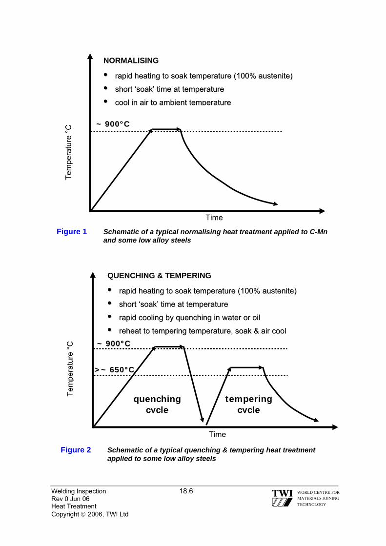
Tem
pera
ture
°C
Figure 1 Schematic of a typical normalising heat treatment applied to C-Mn and some low alloy steels
Time
~~ 990000°°CC
NORMALISING
•• rraappiidd hheeaattiinngg ttoo ssooaakk tteemmppeerraattuurree ((110000%% aauusstteenniittee))
•• sshhoorrtt ‘‘ssooaakk’’ ttiimmee aatt tteemmppeerraattuurree
•• ccooooll iinn aaiirr ttoo aammbbiieenntt tteemmppeerraattuurree
Welding Inspection 18.6 Rev 0 Jun 06 Heat Treatment Copyright © 2006, TWI Ltd
WORLD CENTRE FOR MATERIALS JOINING TECHNOLOGY
Tem
pera
ture
°C
~~ 990000°°CC
QUENCHING & TEMPERING
•• rraappiidd hheeaattiinngg ttoo ssooaakk tteemmppeerraattuurree ((110000%% aauusstteenniittee))
•• sshhoorrtt ‘‘ssooaakk’’ ttiimmee aatt tteemmppeerraattuurree
•• rraappiidd ccoooolliinngg bbyy qquueenncchhiinngg iinn wwaatteerr oorr ooiill
•• rreehheeaatt ttoo tteemmppeerriinngg tteemmppeerraattuurree,, ssooaakk && aaiirr ccooooll
>>~~ 665500°°CC
tempering c
quenching c ycleycle
Time
Figure 2 Schematic of a typical quenching & tempering heat treatment applied to some low alloy steels
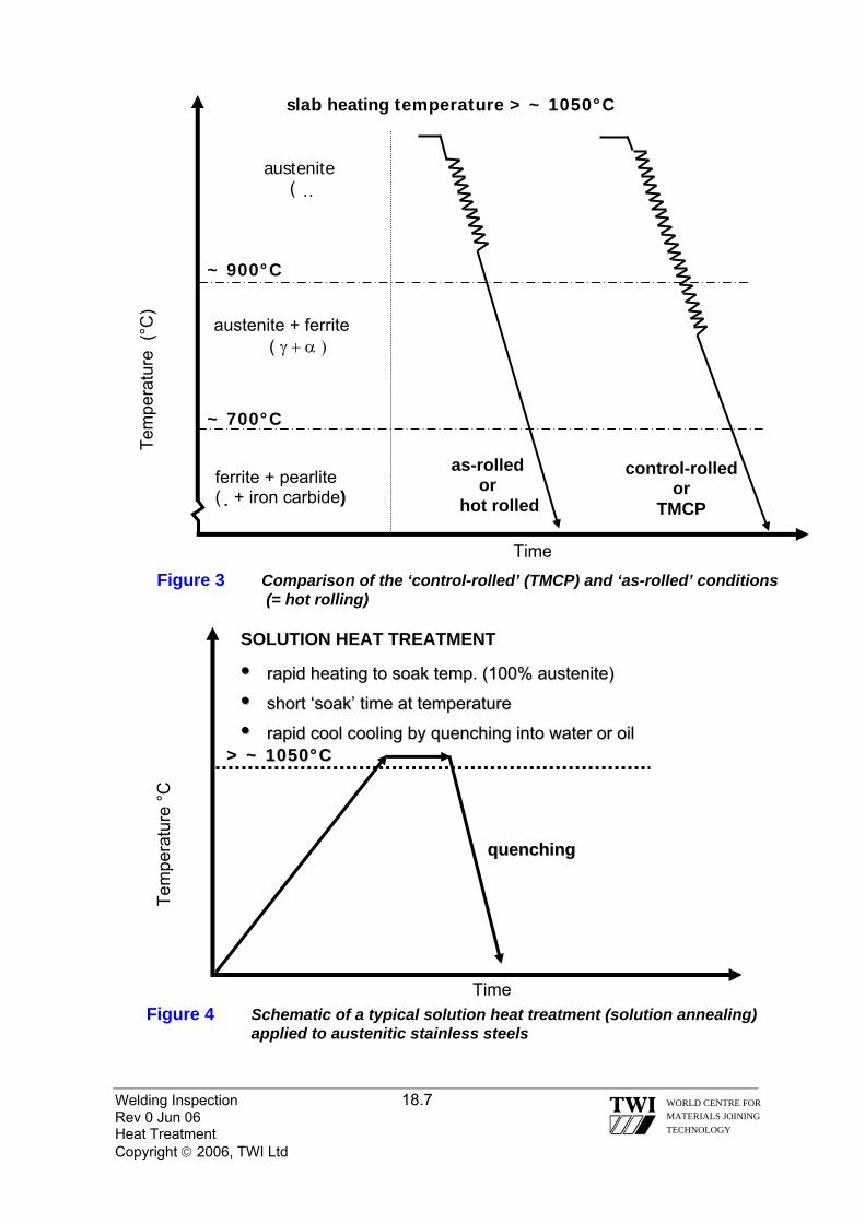
slab heating temperature > ~ 1050°C
Welding Inspection 18.7 Rev 0 Jun 06 Heat Treatment Copyright © 2006, TWI Ltd
WORLD CENTRE FOR MATERIALS JOINING TECHNOLOGY
Figure 3 Comparison of the ‘control-rolled’ (TMCP) and ‘as-rolled’ conditions (= hot rolling)
Tem
pera
ture
(°C
)
~ 900°C
austenite + ferrite ( γ + α )
ferrite + pearlite (�+ iron carbide)
as-rolled or
hot rolled
Time
austenite ( �
~ 700°C
control-rolled or
TMCP
SOLUTION HEAT TREATMENT
•• rraappiidd hheeaattiinngg ttoo ssooaakk tteemmpp.. ((110000%% aauusstteenniittee))
•• short ‘soak’ time at temperature short ‘soak’ time at temperature
•• rapid cool cooling by quenching into water or oil rapid cool cooling by quenching into water or oil
Tem
pera
ture
°C
>> ~~ 11005500°°CC
Figure 4 Schematic of a typical solution heat treatment (solution annealing) applied to austenitic stainless steels
Time
qquueenncchhiinngg

PWHT (C-Mn steels)
•• •• ••
Tem
pera
ture
°C
Welding Inspection 18.8 Rev 0 Jun 06 Heat Treatment Copyright © 2006, TWI Ltd
WORLD CENTRE FOR MATERIALS JOINING TECHNOLOGY
heated bandheated bandtemp.temp.decaydecaybandband
temp.temp.decaydecaybandband
weld seam
Figure 6 Schematic of local PWHT of a pipe girth seam
ccoonnttrroolllleedd hheeaattiinngg rraattee ffrroomm 330000°°CC ttoo ssooaakk tteemmpp..
mmiinniimmuumm ssooaakk ttiimmee aatt tteemmppeerraattuurree
ccoonnttrroolllleedd ccoooolliinngg ttoo ~~ 330000°°CC
Figure 5 Schematic of a typical PWHT applied to C-Mn steels
Time
~~ 660000°°CC
soak time
~~ 330000°°CC
controlled heating & cooling
rates
air cool
Welding Inspection Rev 0 Jun 06 Copyright © 2006, TWI Ltd
WORLD CENTRE FOR MATERIALS JOINING TECHNOLOGY
Section 19
Cutting Processes
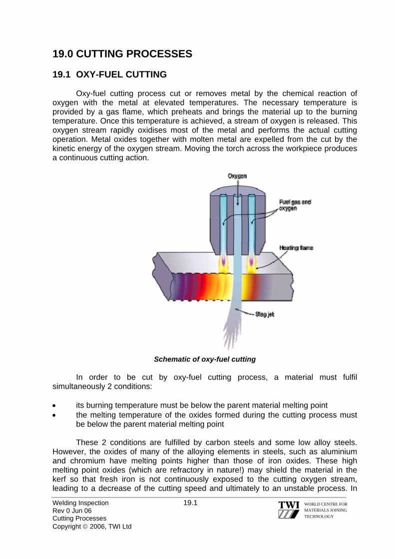
19.0 CUTTING PROCESSES 19.1 OXY-FUEL CUTTING Oxy-fuel cutting process cut or removes metal by the chemical reaction of oxygen with the metal at elevated temperatures. The necessary temperature is provided by a gas flame, which preheats and brings the material up to the burning temperature. Once this temperature is achieved, a stream of oxygen is released. This oxygen stream rapidly oxidises most of the metal and performs the actual cutting operation. Metal oxides together with molten metal are expelled from the cut by the kinetic energy of the oxygen stream. Moving the torch across the workpiece produces a continuous cutting action.
Schematic of oxy-fuel cutting
In order to be cut by oxy-fuel cutting process, a material must fulfil
simultaneously 2 conditions:
• its burning temperature must be below the parent material melting point • the melting temperature of the oxides formed during the cutting process must
be below the parent material melting point These 2 conditions are fulfilled by carbon steels and some low alloy steels. However, the oxides of many of the alloying elements in steels, such as aluminium and chromium have melting points higher than those of iron oxides. These high melting point oxides (which are refractory in nature!) may shield the material in the kerf so that fresh iron is not continuously exposed to the cutting oxygen stream, leading to a decrease of the cutting speed and ultimately to an unstable process. In
Welding Inspection 19.1 Rev 0 Jun 06 Cutting Processes Copyright © 2006, TWI Ltd
WORLD CENTRE FOR MATERIALS JOINING TECHNOLOGY

Welding Inspection 19.2 Rev 0 Jun 06 Cutting Processes Copyright © 2006, TWI Ltd
WORLD CENTRE FOR MATERIALS JOINING TECHNOLOGY
practice, the process is effectively limited to low alloy steels containing <0.25%C, <5%Cr, <5%Mo, <5%Mn and <9%Ni. Advantages of oxy-fuel cutting:
• steels can generally be cut faster than by most machining methods • section shapes and thicknesses that are difficult to produce by mechanical
means can be cut economically by oxy-fuel cutting • basic equipment costs are low compared to machine tools • manual equipment is very portable and can be used on site • cutting direction can be changed rapidly on a small radius • large plates can be cut rapidly in place by moving the torch rather than the plate • is an economical method of plate edge preparation Disadvantages of oxy-fuel cutting: • dimensional tolerances are significantly poorer than machine tool capabilities • the process is essentially limited to cutting carbon and low alloy steels • the preheat flame and expelled red-hot slag present fire and burn hazards to
plant and personnel • fuel combustion and oxidation of the metal require proper fume control and
adequate ventilation • hardenable steels may require preheat and/or postheat adjacent to the cut
edges to control their metallurgical structures and mechanical properties • special process modifications are needed for cutting high alloy steels and cast
irons (i.e. iron powder or flux addition) • being a thermal process, expansion and shrinkage of the components during
and after cutting operation must be taken into consideration 19.1.1 REQUIREMENTS FOR GASES Oxygen used for cutting operations should have a purity of 99,5% or higher. Lower purity will result in a decrease in cutting speed and an increase in consumption of cutting oxygen thus reducing the efficiency of the cutting operation. With oxygen purity below 95% cutting becomes a melt-and-wash action that is usually unacceptable. The preheating flame has the following functions in the cutting operation: • raise the temperature of the steel to the ignition point • add heat energy to the work to maintain the cutting reaction • provide a protective shield between the cutting oxygen stream and the
atmosphere • dislodge from the upper surface of the steel any rust, scale, paint or other
foreign substance that would stop or retard the normal forward progress of the cutting action

Factors to be considered when selecting a particular fuel gas: • the time required for preheating when starting cuts • the effect on cutting speed and productivity • cost and availability • volume of oxygen required per volume of fuel gas to obtain a neutral flame • safety in transporting and handling of gases Some of the more common fuel gases used are acetylene, natural gas (methane), propane, propylene and MAPP gas (methylacetylene propadiene mixture). Fuel gas characteristics and their applications Fuel gas Main characteristics Applications Acetylene Highly focused, high temperature flame
Rapid preheating and piercing Low oxygen requirement
Cutting of thin plates Bevel cuts Short, multi-pierce cuts
Propane Low temperature flame, high heat content Slow preheating and piercing High oxygen requirement
Cutting of thicker sections (100-300mm), long cuts
MAPP Medium temperature flame Cutting underwater Propylene Medium temperature flame Cutting of thicker sections Methane Low temperature flame Cutting of thicker sections 19.1.2 OXY-FUEL GAS CUTTING QUALITY Generally, oxy-fuel cuts are characterised by: • large kerf (<2mm) • low roughness values (Ra<50µm) • poor edge squareness (>0.7mm) • wide HAZ (>1mm)
Welding Inspection 19.3 Rev 0 Jun 06 Cutting Processes Copyright © 2006, TWI Ltd
WORLD CENTRE FOR MATERIALS JOINING TECHNOLOGY
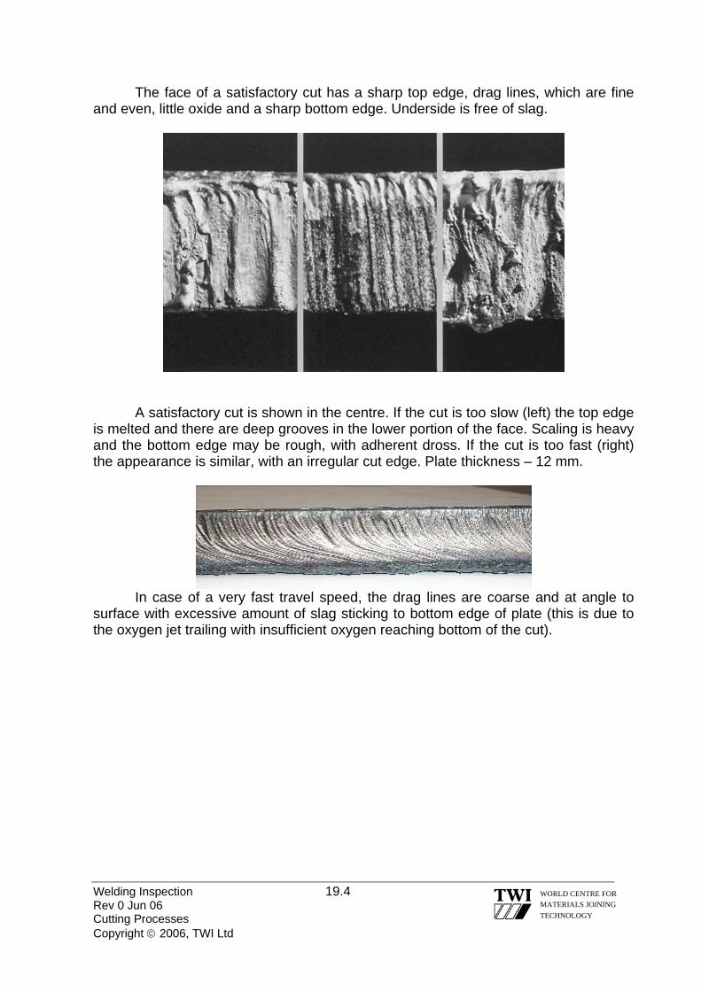
The face of a satisfactory cut has a sharp top edge, drag lines, which are fine and even, little oxide and a sharp bottom edge. Underside is free of slag.
A satisfactory cut is shown in the centre. If the cut is too slow (left) the top edge is melted and there are deep grooves in the lower portion of the face. Scaling is heavy and the bottom edge may be rough, with adherent dross. If the cut is too fast (right) the appearance is similar, with an irregular cut edge. Plate thickness – 12 mm.
In case of a very fast travel speed, the drag lines are coarse and at angle to surface with excessive amount of slag sticking to bottom edge of plate (this is due to the oxygen jet trailing with insufficient oxygen reaching bottom of the cut).
Welding Inspection 19.4 Rev 0 Jun 06 Cutting Processes Copyright © 2006, TWI Ltd
WORLD CENTRE FOR MATERIALS JOINING TECHNOLOGY

A satisfactory cut is again shown in the centre. If the preheating flame is too low (left) the most noticeable effect on the cut edge is deep gouges in the lower part of the cut face. If the preheating flame is too high (right) the top edge is melted, the cut is irregular and there is an excess of adherent dross. Plate thickness – 12 mm.
As before, a satisfactory cut is shown in the centre. If the blowpipe nozzle is too high above the work (left) excessive melting of the top edge occurs with much oxide. If the torch travel speed is irregular (right) uneven spacing of the drag lines can be observed together with irregular bottom surface and adherent oxide. Plate thickness – 12 mm. 19.2 PLASMA ARC CUTTING Plasma arc cutting is an arc cutting process that uses a constricted arc, which removes the molten metal with a high velocity jet of ionised gas issuing from the constricting orifice. First, a pilot arc is struck between a tungsten electrode and a water-cooled nozzle. The arc is then transferred to the workpiece, thus being
Welding Inspection 19.5 Rev 0 Jun 06 Cutting Processes Copyright © 2006, TWI Ltd
WORLD CENTRE FOR MATERIALS JOINING TECHNOLOGY

Welding Inspection 19.6 Rev 0 Jun 06 Cutting Processes Copyright © 2006, TWI Ltd
WORLD CENTRE FOR MATERIALS JOINING TECHNOLOGY
constricted by the orifice downstream of the electrode. As plasma gas passes through this arc, it is heated rapidly to a high temperature, expands and is accelerated as it passes through the constricting orifice towards the workpiece. The orifice directs the super heated plasma stream from the electrode toward the workpiece. When the arc melts the workpiece, the high velocity jet blows away the molten metal. The cutting arc attaches to or “transfers” to the work piece. This is known as the Transferred Arc method. However where materials are non electrical conductors there is a method knon as Non Transferred Arc where the Positive and Negative poles are house inside the torch body creating the arc and the plasma jet stream travels toward the work piece. Advantages of plasma arc cutting: • plasma arc cutting is not only limited to materials which are electrical
conductors; as a consequence, plasma arc cutting is widely used for cutting all types of stainless steels, non-ferrous materials and non electrical conductive materials
• plasma arc cutting operates at a much higher energy level compared to oxy-fuel cutting resulting in faster cutting speed
• instant start-up is particularly advantageous for interrupted cutting; this also allows cutting without preheat
Disadvantages of plasma arc cutting: • dimensional tolerances are significantly poorer than machine tool capabilities • the process introduces hazards such as fire, electric shock (due to the high
OCV!), intense light, fumes, gases and noise levels that may not be present with other processes. However, in case of underwater cutting, the level of fumes, UV radiation and noise are reduced to a low level.
• compared to oxy-fuel cutting, plasma arc cutting equipment tends to be more expensive and requires a fairly large amount of electric power
• being a thermal process, expansion and shrinkage of the components during and after cutting operation must be taken into consideration

Transferred Arc Non Transferred
Schematic of plasma arc cutting
19.3 ARC-AIR GOUGING During arc air gouging process, the metal to be gouged or cut is melted with an electric arc and blown away with a high velocity jet of compressed air. A special torch directs the compressed air stream along the electrode and underneath it. The torch is connected to an arc welding machine and any compressed air line, which delivers approximately 690 kPa of compressed air. Since the pressure is not critical, a regulator is not necessary. The electrode is made out of graphite and is copper coated to increase the current pick-up and operating life. This process is usually used for gouging and bevelling, being able to produce U and J preps. It can be applied to both ferrous and non-ferrous materials.
Schematic of arc-air gouging
Welding Inspection 19.7 Rev 0 Jun 06 Cutting Processes Copyright © 2006, TWI Ltd
WORLD CENTRE FOR MATERIALS JOINING TECHNOLOGY

Welding Inspection 19.8 Rev 0 Jun 06 Cutting Processes Copyright © 2006, TWI Ltd
WORLD CENTRE FOR MATERIALS JOINING TECHNOLOGY
Advantages of arc-air gouging: • fast – it is approximately 5 times faster than chipping • easily controllable, removes defects with precision. Defects are clearly visible
and may be followed with ease. The depth of cut is easily regulated and slag does not deflect or hamper the cutting action.
• low equipment cost – no gas cylinders or regulators are necessary except on site.
• economical to operate – no oxygen or fuel gas required. The welder may also do the gouging (there are no qualification requirements for this operation!).
• easy to operate – the equipment is similar to MMA equipment except the torch and air supply hose.
• compact – the torch is not much larger than a MMA electrode holder, allowing work in confined areas.
• Versatile Disadvantages of arc-air gouging: • other cutting processes usually produce a better and quicker cut • requires a large volume of compressed air • increase the carbon content leading to an increase in hardness in case of cast
iron and hardenable metals. In case of stainless steels it can lead to carbide precipitation and sensitisation. For this reason, grinding of the carbured layer usually follows arc-air gouging.
• introduces hazards such as fire (due to discharge of sparks and molten metal), fumes, noise and intense light.
19.4 MANUAL METAL ARC GOUGING In this case the arc is formed between the tip of the electrode and the workpiece. It requires special purpose electrodes with thick flux coatings to generate a strong arc force and gas stream. Unlike MMA welding where a stable weld pool must be maintained, this process forces the molten metal away from the arc zone to leave a clean cut surface. The gouging process is characterised by the large amount of gas, which is generated to eject the molten metal. However, because the arc/gas stream is not as powerful as a gas or a separate air jet, the surface of the gouge is not as smooth as an oxy-fuel gouge or air carbon arc gouge.

Schematic of manual metal arc gouging
Although DCEN is preferred, an AC constant current power source can also be used. MMA gouging is used for localised gouging operations, removal of defects for example, and where it is more convenient to switch from a welding electrode to a gouging electrode rather than use specialised equipment. Compared with alternative gouging processes, metal removal rates are low and the quality of the gouged surface is inferior. When correctly applied, MMA gouging can produce relatively clean gouged surfaces. For general applications, welding can be carried out without the need to dress by grinding. However when gouging stainless steel, a thin layer of higher carbon content material will be produced - this should be removed by grinding.
Welding Inspection 19.9 Rev 0 Jun 06 Cutting Processes Copyright © 2006, TWI Ltd
WORLD CENTRE FOR MATERIALS JOINING TECHNOLOGY
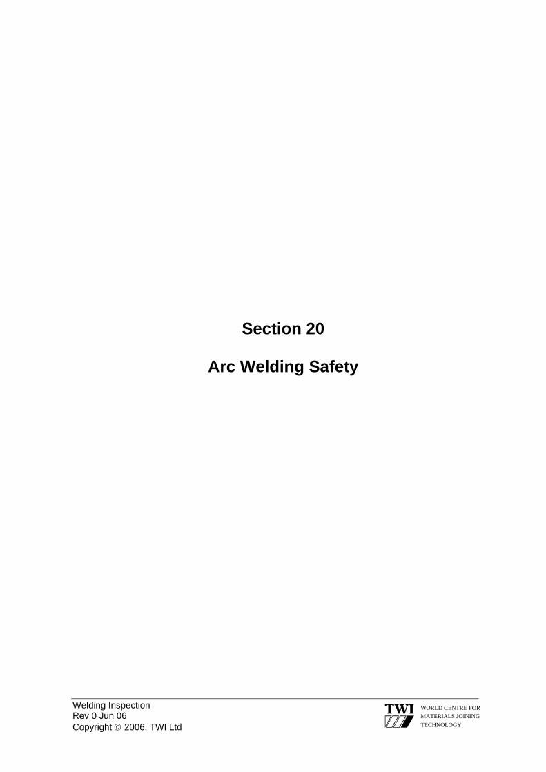
Welding Inspection Rev 0 Jun 06 Copyright © 2006, TWI Ltd
WORLD CENTRE FOR MATERIALS JOINING TECHNOLOGY
Section 20
Arc Welding Safety
Welding Inspection 20.1 Rev 0 Jun 06 Arc Welding Safety Copyright © 2006, TWI Ltd
WORLD CENTRE FOR MATERIALS JOINING TECHNOLOGY
20.0 ARC WELDING SAFETY 20.1 GENERAL
Working in a safe manner, whether in the workshop or on site, is an important consideration in any welding operation. The responsibility for safety is on the individuals, not only for their own safety, but also for other people’s safety. The Visual/Welding Inspector has an important function in ensuring that safe working legislation is in place and safe working practices are implemented. The Inspector may be required to carry out safety audits of welding equipment prior to welding, implement risk assessment/permit to work requirements or monitor the safe working operations for a particular task, during welding. There are a number of documents that the inspector may refer to for guidance: • Government Legislation – The Health & Safety at Work Act. • Health & Safety Executive – COSHH Regulations, Statutory instruments. • Work or site instructions – Permits to work, risk assessment documents etc • Local Authority Requirements.
There are four aspects of arc welding safety that the Visual/ Welding Inspector needs to consider • Electric Shock • Heat and Light • Fumes and Gases • Noise 20.2 ELECTRIC SHOCK
The hazard of electric shock is one of the most serious and immediate risks facing personnel involved in the welding operation.
Contact with metal parts, which are "electrically hot”, can cause injury or death
because of the effect of the shock upon the body or because of a fall as a result of the reaction to electric shock.
The electric shock hazard associated with arc welding may be divided into two categories:
• Primary voltage shock - 230 or 460 volts • Secondary voltage shock - 60 to 100 volts
Primary voltage shock is very hazardous because it is much greater than the
secondary voltage of the welding equipment. Electric shock from the primary (input) voltage can occur by touching a lead inside the welding equipment with the power to

Welding Inspection 20.2 Rev 0 Jun 06 Arc Welding Safety Copyright © 2006, TWI Ltd
WORLD CENTRE FOR MATERIALS JOINING TECHNOLOGY
the welder switched on while the body or hand touches the welding equipment case or other earthed metal. Residual Circuit Devices (RCDs) connected to circuit breakers of sufficient capacity will help to protect the welder and other personnel from the danger of primary electric shock.
Secondary voltage shock occurs when touching a part of the electrode circuit - perhaps a damaged area on the electrode cable - and another part of the body touches both sides of the welding circuit (electrode and work, or welding earth) at the same time.
Most welding equipment is unlikely to exceed open circuit voltages of 100V. Electric shock, even at this level can be serious, so the welding circuit should be fitted with low voltage safety devices, to minimise the potential of secondary electric shock. A correctly wired welding circuit should contain three leads: • A welding lead, from one terminal of the power source to the electrode holder
or welding torch. • A welding return lead to complete the circuit, from the work to the other terminal
of the power source. • An earth lead, from the work to an earth point. The power source should also
be earthed. All three leads should be capable of carrying the highest welding current required.
In order to establish whether the capacity of any piece of current carrying equipment is adequate for the job, the Visual/ Welding Inspector can refer to the Duty Cycle of the equipment. All current carrying welding equipment is rated in terms of: Duty Cycle.
All current carrying conductors heat up when welding current is passed through them. Duty Cycle is essentially a measure of the capability of the welding equipment in terms of the ratio of welding time to total time, which can be expressed as:
Duty Cycle = Welding Time x 100 Total Time
By observing this ratio the current carrying conductors will not be heated above their rated temperature. Duty cycles are based on a total time of 10 minutes. Example A power source has a rated output of 350Amps at 60% Duty Cycle. This means that this particular power source will deliver 350 amps (its rated output) for six minutes out of every ten minutes without overheating.

Welding Inspection 20.3 Rev 0 Jun 06 Arc Welding Safety Copyright © 2006, TWI Ltd
WORLD CENTRE FOR MATERIALS JOINING TECHNOLOGY
Failure to carefully observe the Duty Cycle of a piece of equipment can over stress the part, and in the case of welding equipment cause overheating leading to instability and the potential for electric shock. 20.3 HEAT AND LIGHT 20.3.1 HEAT
In arc welding, electrical energy is converted into heat energy and light energy, both of which can have serious health consequences.
The welding arc creates sparks, which have the potential to cause flammable materials near the welding area to ignite and cause fires. The welding area should be clear of all combustible materials and it is good practice for the Inspector to know where the nearest fire extinguishers are situated and know the correct type of fire extinguisher to use if a fire does break out.
Welding sparks can cause serious burns, so protective clothing, such as welding gloves, flame retardant coveralls and leathers must be worn around any welding operation in order to protect against heat and sparks. 20.3.2 LIGHT Light radiation is emitted by the welding arc in three principal ranges:
Type Wavelength (nanometres)
Infrared (heat) >700 Visible light 400-700 Ultraviolet radiation <400 20.3.2.1 ULTRAVIOLET RADIATION (UV)
All arc processes generate UV. Excess exposure to UV causes skin inflammation, and possibly even skin cancer or permanent eye damage. However the main risk amongst welders and Inspectors is for inflammation of the cornea and conjunctiva, commonly known as 'arc eye' or 'flash'.
Arc eye is caused by UV radiation. This damages the outmost protective layer of cells in the cornea. Gradually the damaged cells die and fall off the cornea exposing highly sensitive nerves in the underlying cornea to the comparatively rough inner part of the eyelid. This causes intense pain, usually described as 'sand in the eye'. The pain becomes even more acute if the eye is then exposed to bright light.
Arc eye develops some hours after exposure, which may not even have been noticed. The 'sand in the eye' symptom and pain usually lasts for 12 - 24 hours, but

Welding Inspection 20.4 Rev 0 Jun 06 Arc Welding Safety Copyright © 2006, TWI Ltd
WORLD CENTRE FOR MATERIALS JOINING TECHNOLOGY
can be longer in more severe cases. Fortunately, arc eye is almost always a temporary condition. In the unlikely event of prolonged and frequently repeated exposures, permanent damage can occur.
Treatment of arc eye is simple: rest in a dark room. A qualified person or hospital Casualty Departments can administer various soothing anaesthetic eye drops. These can provide almost instantaneous relief. Prevention is better than cure and wearing safety glasses with side shields will considerably reduce the risk of this condition. Ultraviolet effects upon the skin
The UV from arc processes does not produce the browning effect of sunburn; but does result in reddening and irritation caused by changes in the minute surface blood vessels. In extreme cases, the skin may be severely burned and blisters may form. The reddened skin may die and flake off in a day or so. Where there has been intense prolonged or frequent exposure, skin cancers can develop. 20.3.2.2 VISIBLE LIGHT
Intense visible light particularly approaching UV or 'blue light' wavelengths passes through the cornea and lens and can dazzle and, in extreme cases, damage the network of optically sensitive nerves on the retina. Wavelengths of visible light approaching the infrared have slightly different effects but can produce similar symptoms. Effects depend on the duration and intensity of exposure and to some extent, upon the individual's natural reflex action to close the eye and exclude the incident light. Normally this dazzling does not produce a long-term effect. 20.3.2.3 INFRARED RADIATION
Infrared radiation is of longer wavelength than the visible light frequencies, and is perceptible as heat. The main hazard to the eyes is that prolonged exposure (over a matter of years) causes a gradual but irreversible opacity of the lens. Fortunately, the infrared radiation emitted by normal welding arcs causes damage only within a comparatively short distance from the arc. There is an immediate burning sensation in the skin surrounding the eyes should they be exposed to arc heat. The natural human reaction is to move or cover up to prevent the skin heating, which also reduces eye exposure.
BS EN169 specifies a range of permanent filter shades of gradually increasing optical density which limit exposure to radiation emitted by different processes at different currents. It must be stressed that shade numbers indicated in the standard and the corresponding current ranges are for guidance only. 20.4 FUMES AND GASES
20.4.1 FUMES

Welding Inspection 20.5 Rev 0 Jun 06 Arc Welding Safety Copyright © 2006, TWI Ltd
WORLD CENTRE FOR MATERIALS JOINING TECHNOLOGY
Because of the variables involved in fume generation from arc welding and allied processes (such as the welding process and electrode, the base metal, coatings on the base metal and other possible contaminants in the air), the dangers of welding fume can be considered in a general way. Although health considerations vary according to the type of fume composition and individual reactions, the following holds true for most welding fume.
The fume plume contains solid particles from the consumables, base metal and base metal coating. Depending on the length of exposure to these fumes, most acute effects are temporary and include symptoms of burning eyes and skin, dizziness, nausea and fever.
For example, zinc fumes can cause metal fume fever, a temporary illness that is similar to the flu. Chronic, long-term exposure to welding fumes can lead to siderosis (iron deposits in the lungs) and may affect pulmonary function.
Cadmium, however, is a different story. This toxic metal can be found on steel as a coating or in silver solder. Cadmium fumes can be fatal even under brief exposure, with symptoms much like those of metal fume fever. These two should not be confused. Twenty minutes of welding in the presence of cadmium can be enough to cause fatalities, with symptoms appearing within an hour and death five days later. 20.4.2 GASES
The gases that result from an arc welding process also present a potential hazard. Most of the shielding gases (argon, helium and carbon dioxide) are non-toxic. When released, however, these gases displace oxygen in the breathing air, causing dizziness, unconsciousness and death the longer the brain is denied oxygen.
Some degreasing compounds such as trichlorethylene and perchlorethylene can decompose from the heat and ultraviolet radiation to produce toxic gases. Ozone and nitrogen oxides are produced when UV radiation hits the air. These gases cause headaches, chest pains, irritation of the eyes and itchiness in the nose and throat.
To reduce the risk of hazardous fumes and gases, keep the head out of the fume plume. As obvious as this sounds, it is a common cause of fume and gas overexposure because the concentration of fumes and gases is greatest in the plume. In addition, use mechanical ventilation or local exhaust at the arc to direct the fume plume away from the face. If this is not sufficient, use fixed or moveable exhaust hoods to draw the fume from the general area. Finally, it may be necessary to wear an approved respiratory device if sufficient ventilation cannot be provided.
As a rule of thumb, if the air is visibly clear and the welder is comfortable, the ventilation is probably adequate.
To identify hazardous substances, first read the material safety data sheet for the consumable to see what fumes can be reasonably expected from use of the product.

Welding Inspection 20.6 Rev 0 Jun 06 Arc Welding Safety Copyright © 2006, TWI Ltd
WORLD CENTRE FOR MATERIALS JOINING TECHNOLOGY
Refer to the Occupational Exposure Limit (OEL) as defined in the COSHH
regulations which gives maximum concentrations to which a healthy adult can be exposed to any one substance.
Second, know the base metal and determine if a paint or coating would cause toxic fumes or gases.
Particular attention should also be made to the dangers of asphyxiation when welding in confined spaces. Risk assessment, permits to work and gas testing are some of the necessary actions required to ensure the safety of all personnel. 20.5 NOISE
Exposure to loud noise can permanently damage hearing. Noise can also cause stress and increase blood pressure. Working in a noisy environment for long periods can contribute to tiredness, nervousness and irritability. If the noise exposure is greater than 85 decibels averaged over an 8-hour period then hearing protection must be worn, and annual hearing tests should be carried out.
Normal welding operations are not associated with noise level problems with
two exceptions: Plasma arc welding and air carbon arc cutting. If either of these two operations is to be performed then hearing protectors must be worn. The noise associated with welding is usually due to ancillary operations such as chipping, grinding and hammering. Hearing protection must be worn when carrying out, or when working in the vicinity of, these operations. 20.6 SUMMARY
The best way to manage the risks associated with welding is by implementing risk management programs. Risk management is a method that requires the identification of hazards, assessment of the risks and implementation of suitable controls to reduce the risk to an acceptable level.
It is essential to evaluate and review a risk management program. Evaluation involves ensuring that control measures have eliminated or reduced the risks, and review aims to check that the process is working effectively to identify hazards and manage risks.
It is quite likely that the Visual/Welding Inspector would be involved in managing the risks associated with welding as part of their duties.

Welding Inspection Rev 0 Jun 06 Copyright © 2006, TWI Ltd
WORLD CENTRE FOR MATERIALS JOINING TECHNOLOGY
Section 21
The Weldability of Steels

Welding Inspection 21.1 Rev 0 Jun 06 Weldability of Steels Copyright © 2006 TWI Ltd
WORLD CENTRE FOR MATERIALS JOINING TECHNOLOGY
21.0 THE WELDABILITY OF STEELS 21.1 INTRODUCTION
The term ‘weldability’ simply means the ability to be welded and many types of steel that are weldable have been developed for a wide range of applications.
However, it is the ease or difficulty of making a weld with suitable properties and free from defects varies and so some steels are described as having ‘good weldability’ whereas others may be said to have ‘poor weldability’. A steel is usually said to have poor weldability if it is necessary take special precautions to avoid a particular type of imperfection. Another reason for poor weldability may be the need to weld within a very narrow range of parameters to achieve properties required for the joint. 21.2 FACTORS THAT AFFECT WELDABILITY
A number of inter-related factors determine whether a steel is said to have good or poor weldability. These are:
• the actual chemical composition
• the weld joint configuration
• the welding process to be used
• the properties required from the weldment For steels with poor weldability it is particularly necessary to ensure that:
• welding procedure specifications give welding conditions that do not cause cracking but achieve the specified properties
• welders work strictly in accordance with the specified welding conditions
• welding inspectors regularly monitor welders to ensure they are working strictly in accordance the WPSs
Having a good understanding of the characteristics, causes, and ways of
avoiding imperfections in steel weldments should enable welding inspectors to focus attention on the most influential welding parameters when steels with poor weldability are being used.

Welding Inspection 21.2 Rev 0 Jun 06 Weldability of Steels Copyright © 2006 TWI Ltd
WORLD CENTRE FOR MATERIALS JOINING TECHNOLOGY
21.3 HYDROGEN CRACKING
During fabrication by welding, cracks can occur in some types of steel, due to the presence of hydrogen. The technical name for this type of cracking is ‘hydrogen induced cold cracking’ (HICC) but it is often referred to by other names that describe various characteristics of hydrogen cracks, namely:
• cold cracking - cracks occur when the weld has cooled down
• HAZ cracking - cracks tend to occur mainly in the HAZ
• delayed cracking - cracks may occur some time after welding has finished (possibly up to ~48h)
• under-bead cracking - cracks occur in the HAZ beneath a weld bead
Although most hydrogen cracks occur in the HAZ, there are circumstances when they may form in weld metal. Figure 1 is a schematic showing typical locations of HAZ hydrogen cracks. Figure 2 shows hydrogen crack in the HAZ of a fillet weld. 21.3.1 FACTORS INFLUENCING SUSCEPTIBILITY TO HYDROGEN CRACKING
Hydrogen cracking in the HAZ of a steel occurs when 4 conditions exist at the same time, namely:
• hydrogen is present (above a certain level)
• a tensile stress is acting on the weld (above a certain level)
• a susceptible HAZ microstructure is present
• the weldment is at a low temperature (near to ambient temperature)
These 4 conditions (4 factors) are mutually interdependent so that the influence of one condition (its’ active level) depends on how active the others 3 factors are. 21.3.2 CRACKING MECHANISM
Hydrogen (H) can enter the molten weld metal when hydrogen containing molecules are broken down into H atoms in the welding arc.
Because H atoms are very small they can move about (diffuse) in solid steel and while weld metal is hot they can diffuse to the weld surface and escape into the atmosphere.

Welding Inspection 21.3 Rev 0 Jun 06 Weldability of Steels Copyright © 2006 TWI Ltd
WORLD CENTRE FOR MATERIALS JOINING TECHNOLOGY
However, at lower temperatures H cannot diffuse as quickly and if the weldment cools down quickly to ambient temperature H will become trapped - usually the HAZ.
If the HAZ has a susceptible microstructure – indicated by being relatively hard and brittle, there are also relatively high tensile stresses in the weldment then H cracking can occur.
The precise mechanism that causes cracks to form is complex but H is believed to cause embrittlement of regions of the HAZ so that high-localised stresses cause cracking rather than plastic straining. 21.3.3 AVOIDING HAZ HYDROGEN CRACKING
Because the factors that cause cracking are interdependent, and each need to be at an active level at the same time, cracking can be avoided by ensuring that at least one of the 4 factors is not active during welding.
Methods that can be used to minimise the influence of each of the 4 factors are considered in the following sub-sections.
Hydrogen The principal source of hydrogen is moisture (H2O) and the principal source of
moisture is welding flux. Some fluxes contain cellulose and this can be a very active source of hydrogen.
Welding processes that do not require flux can be regarded as low hydrogen processes.
Other sources of hydrogen are moisture present in rust or scale, and oils and greases (hydrocarbons). Reducing the influence of Hydrogen is possible by: ensuring that fluxes (coated electrodes, flux-cored wires & SAW fluxes) are low in H when welding commences
low H electrodes must be either baked & then stored in a hot holding oven or supplied in vacuum-sealed packages; basic agglomerated SAW fluxes should be kept in a heated silo before issue to maintain their as-supplied, low moisture, condition check the diffusible hydrogen content of the weld metal (sometimes it is specified on the test certificate)
ensuring that a low H condition is maintained throughout welding by not allowing fluxes to pick-up moisture from the atmosphere
low hydrogen electrodes must be issued in small quantities and the exposure time limited; heated ‘quivers’ facilitate this control;

Welding Inspection 21.4 Rev 0 Jun 06 Weldability of Steels Copyright © 2006 TWI Ltd
WORLD CENTRE FOR MATERIALS JOINING TECHNOLOGY
flux cored wire spools that are not seamless should be covered or returned to a suitable storage condition when not in use; basic agglomerated SAW fluxes should be returned to the heated silo when welding is not continuous check the amount of moisture present in the shielding gas by checking the dew point(must be bellow -60°C)
» ensuring that the weld zone is dry and free from rust/scale and oil/grease
Tensile Stress There are always tensile stresses acting on a weld because there are always
residual stresses from welding. The magnitude of the tensile stresses is mainly dependent on the thickness of
the steel at the joint, the heat input, the joint type, and the size and weight of the components being welded.
Tensile stresses in highly restrained joints may be as high as the yield strength of the steel and this is usually the case in large components with thick joints and it is not a factor that can easily be controlled. The only practical ways of reducing the influence of residual stresses may be by:
• avoiding stress concentrations due to poor fit-up
• avoiding poor weld profile (sharp weld toes)
• apply a stress relief heat treatment after welding
• increase the travel speed as practicable in order to reduce the heat input
• keep weld metal volume to an as low level as possible
These measures are particularly important when welding some low alloy steels that have particularly sensitivity to hydrogen cracking.
Susceptible HAZ Microstructure A susceptible HAZ microstructure is one that contains a relatively high
proportion of hard brittle phases of steel - particularly martensite.
The HAZ hardness is a good indicator of susceptibility and when it exceeds as certain value a particular steel is considered to be susceptible. For C & C-Mn steels this hardness value is ~ 350HV and susceptibility to H cracking increases as hardness increases above this value. The maximum hardness of an HAZ is influenced by:
• the chemical composition of the steel
• the cooling rate of the HAZ after each weld run is made.

Welding Inspection 21.5 Rev 0 Jun 06 Weldability of Steels Copyright © 2006 TWI Ltd
WORLD CENTRE FOR MATERIALS JOINING TECHNOLOGY
For C & C-Mn steels a formula has been developed to be able to assess how
the chemical composition will influence the tendency for significant HAZ hardening - the Carbon Equivalent Value (CEV) formula. The CEV formula most widely used (and adopted by IIW) is: CEViiw = % C + %Mn + %Cr + %Mo + %V + %Ni + %Cu 6 5 15
The CEV of a steel is calculated by inserting the material test certificate values shown for chemical composition into the formula. The higher the CEV of a steel the greater is its’ susceptibility to HAZ hardening and therefore the greater the susceptibility to H cracking.
The element with most influence on HAZ hardness is Carbon. The faster the rate of HAZ cooling after each weld run, the greater the tendency for hardening. Cooling rate tends to increase as:
• heat input decreases (lower energy input)
• joint thickness increases (bigger heat sink) Avoiding a susceptible HAZ microstructure (for C & C-Mn steels) requires:
• procuring steel with a CEV that is at the low-end of the range for the steel
grade(limited scope of effectiveness)
• using moderate welding heat input so that the weld does not cool quickly (and give HAZ hardening)
• applying pre-heat so that the HAZ cools more slowly (and does not show
significant HAZ hardening); in multi-run welds, maintain a specific interpass temperature
For low alloy steels, with additions of elements such as Cr, Mo & V, the CEV
formula is not applicable and so must not be used to judge the susceptibility to hardening. The HAZ of these steels will always tend to be relatively hard regardless of heat input and pre-heat and so this is a ‘factor’ that cannot be effectively controlled to reduce the risk of H cracking. This is the reason why some of the low alloy steels have greater tendency to show hydrogen cracking than in weldable C & C-Mn steels, which enable HAZ hardness to be controlled.
Weldment at Low Temperature Weldment temperature has a major influence on susceptibility to cracking
mainly by influencing the rate at which H can move (diffuse) through the weld and

Welding Inspection 21.6 Rev 0 Jun 06 Weldability of Steels Copyright © 2006 TWI Ltd
WORLD CENTRE FOR MATERIALS JOINING TECHNOLOGY
HAZ. While a weld is relatively warm (> ~300°C) H will diffuse quite rapidly and escape into the atmosphere rather than be trapped and cause embrittlement.
Reducing the influence of low weldment temperature (and the risk of trapping H in the weldment) can be effected by:
• applying a suitable pre-heat temperature (typically 50 to ~250°C)
• preventing the weld from cooling down quickly after each pass by maintaining the preheat and the specific interpass temperature during welding
• maintaining the pre-heat temperature (or raising it to ~250°C) when welding
has finished and holding the joint at this temperature for a number of hours (minimum 2 hours) to facilitate the escape of H (called post-heat *) * post-heat must not be confused with PWHT at a temp. ≥ ~600°C
21.3.4 HYDROGEN CRACKING IN WELD METAL
Hydrogen cracks can form in steel weld metal under certain circumstances. The mechanism of cracking, and identification of all the influencing factors, is less clearly understood than for HAZ cracking but it can occur when welding conditions cause H to become trapped in weld metal rather than in HAZ.
Hydrogen cracks in weld metal remain within an individual weld bead and so they are usually quite short (few mm long). The cracks lie at 45° to the direction of principle tensile stress in the weld metal and this is usually the longitudinal axis of the weld (Figure 3).
There are not any well-defined ‘rules’ for avoiding weld metal hydrogen cracks apart from: • ensure a low hydrogen welding process is used • apply preheat and maintain a specific interpass temperature
BS EN 1011-2 entitled ‘Welding – Recommendations for welding of metallic
materials – Part 2: Arc welding of ferritic steels’ gives in Annex C practical guidelines about how to avoid H cracking. Practical controls are based principally on the application of pre-heat and control of potential H associated with the welding process.

Welding Inspection 21.7 Rev 0 Jun 06 Weldability of Steels Copyright © 2006 TWI Ltd
WORLD CENTRE FOR MATERIALS JOINING TECHNOLOGY
21.4 SOLIDIFICATION CRACKING
The technically correct name for cracks that form during weld metal solidification is solidification cracks but other names are sometimes used when referring to this type of cracking, namely:
• hot cracking - they occur at high temperatures – while the weld is hot
• centreline cracking - cracks may appear down the centreline of the weld bead
• crater cracking - small cracks in weld craters are solidification cracks
Because a weld metal may be particularly susceptible to solidification cracking it may be said to show hot shortness because it is short of ductility when hot and so tends to crack. Figure 4 shows a transverse section of a weld with a typical centreline solidification crack. 21.4.1 FACTORS INFLUENCING SUSCEPTIBILITY TO SOLIDIFICATION CRACKING Solidification cracking occurs when 3 conditions exist at the same time, namely:
• the weld metal has a susceptible chemical composition
• the welding conditions used give an unfavourable bead shape
• high level of restraint or tensile stresses present in the weld area 21.4.2 CRACKING MECHANISM
All weld metals solidify over a temperature range and since solidification starts at the fusion line towards the centreline of the weld pool, during the last stages of weld bead solidification there may be enough liquid present to form a weak zone in the centre of the bead. This liquid film is the result of low melting point constituents being pushed ahead of the solidification front.
During solidification, tensile stresses start to build-up due to contraction of the solid parts of the weld bead, and it is these stresses that can cause the weld bead to rupture. These circumstances result in a weld bead showing a centreline crack that is present as soon as the bead has been deposited.
Centreline solidification cracks tend to be surface breaking at some point in their length and can be easily seen during visual inspection because they tend to be relatively wide cracks.

Welding Inspection 21.8 Rev 0 Jun 06 Weldability of Steels Copyright © 2006 TWI Ltd
WORLD CENTRE FOR MATERIALS JOINING TECHNOLOGY
21.4.3 AVOIDING SOLIDIFICATION CRACKING
Avoiding solidification cracking requires the influence of one of the factors responsible, to be reduced to an inactive level.
Weld Metal Composition Most C & C-Mn steel weld metals made by modern steelmaking methods do
not have chemical compositions that are particularly sensitive to solidification cracking.
However, these weld metals can become sensitive to this type of cracking if they are ‘contaminated’ with elements, or compounds, that produce relatively low melting point films in weld metal.
Sulphur and copper are elements that can make steel weld metal sensitive to solidification cracking if they are present in the weld at relatively high levels. Sulphur contamination may lead to the formation of iron sulphides that remain liquid when the bead has cooled down as low as ~980°C, whereas bead solidification started at above 1400°C.
The source of sulphur may be contamination by oil or grease or it could be picked up from the less refined parent steel being welded by dilution into the weld.
Copper contamination in weld metal can be similarly harmful because it has low solubility in steel and can form films that are still molten at ~1100°C.
Avoiding solidification cracking (of an otherwise non-sensitive weld metal) requires the avoidance of contamination with potentially harmful materials by: -
» ensuring weld joints are thoroughly cleaned immediately before welding
» ensuring that any copper containing welding ‘accessories’ are suitable/in suitable condition - such as backing-bars and contact tips used for GMAW, FCAW and SAW
Unfavourable Welding Conditions
Unfavourable welding conditions are those that encourage weld beads to solidify so that low melting point films become ‘trapped’ at the centre of a solidifying weld bead and become the weak zones for easy crack formation.
Figure 5 shows a schematic of a weld bead that has solidified using unfavourable welding conditions associated with centreline solidification cracking.
The weld bead has a cross-section that is quite deep and narrow – a width-to-depth ratio < ~2 and the solidifying dendrites have ‘pushed’ the lower melting point liquid to the centre of the bead where it has become trapped. Since the surrounding

Welding Inspection 21.9 Rev 0 Jun 06 Weldability of Steels Copyright © 2006 TWI Ltd
WORLD CENTRE FOR MATERIALS JOINING TECHNOLOGY
material is shrinking as a result of cooling, this film would be subjected to tensile stress, which leads to cracking.
In contrast, Figure 6 shows a bead that has a width-to-depth ratio that is >>2. This bead shape shows lower melting point liquid ‘pushed’ ahead of the solidifying dendrites but it does not become trapped at the bead centre. Thus, even under tensile stresses resulting from cooling, this film is “self-healing” and cracking is avoided
SAW and spray-transfer GMAW are more likely to give weld beads with an unfavourable width-to-depth ratio than the other arc welding processes. Also, electron beam and LASER welding processes are extremely sensitive to this kind of cracking as a result of the deep, narrow beads produced.
Avoiding unfavourable welding conditions that lead to centreline solidification cracking (of weld metals with sensitive compositions) may require significant changes to welding parameters, such as:-
• reducing the welding current (to give a shallower bead)
and
• reducing the welding speed (to give a wider weld bead)
Avoiding unfavourable welding conditions that lead to crater cracking of a
sensitive weld metal requires changes to the technique used at the end of a weld when the arc is extinguished, such as:
• for TIG welding, use a current ‘slope-out’ device so that the current, and weld
pool depth gradually reduce before the arc is extinguished (gives more favourable weld bead width-to-depth ratio). It is also a common practice to backtrack the bead slightly before breaking the arc or lengthen the arc gradually to avoid crater cracks.
• for TIG welding, ‘modify’ weld pool solidification mode by feeding the filler wire
into the pool until solidification is almost complete and avoiding a concave crater
• for MMA, modify the weld pool solidification mode by reversing the direction of
travel at the end of the weld run so that crater is filled

Welding Inspection 21.10 Rev 0 Jun 06 Weldability of Steels Copyright © 2006 TWI Ltd
WORLD CENTRE FOR MATERIALS JOINING TECHNOLOGY
21.5 LAMELLAR TEARING
Lamellar tearing is a type of cracking that occurs only in steel plate or other rolled products underneath a weld. Characteristics of lamellar tearing are:
• cracks only occur in the rolled plate
• cracks usually form close to, but just outside, the HAZ
• cracks tend to lie parallel to surface of the plate (and the fusion boundary of the weld), having a stepped aspect
The above characteristics can be seen in Figure 7 (a). 21.5.1 FACTORS INFLUENCING SUSCEPTIBILITY TO LAMELLAR TEARING Lamellar tearing occurs when 2 conditions exist at the same time, namely:
• a susceptible rolled plate is used to make a weld joint
• high stresses act in the through-thickness direction of the susceptible plate (known as the short-transverse direction)
Susceptible Rolled Plate A plate that is susceptible to lamellar tearing has very low ductility in the
through-thickness direction (short-transverse direction) and is only able to accommodate the residual stresses from welding by tearing rather than by plastic straining.
Low through-thickness ductility in rolled plate is caused by the presence of numerous non-metallic inclusions in the form of elongated stringers. The inclusions form in the ingot but are flattened and elongated during hot rolling of the plate.
Non-metallic inclusions associated with lamellar tearing are principally manganese sulphides and manganese silicates.
High Through-thickness Stress Weld joints that are T, K & Y configurations end up with a tensile residual stress
component in the through-thickness direction.
The magnitude of the through-thickness stress increases as the restraint (rigidity) of the joint increases. Plate thickness and size of weld are the main influencing factors and it is in thick section, full penetration T, K & Y joints that lamellar tearing is more likely to occur.
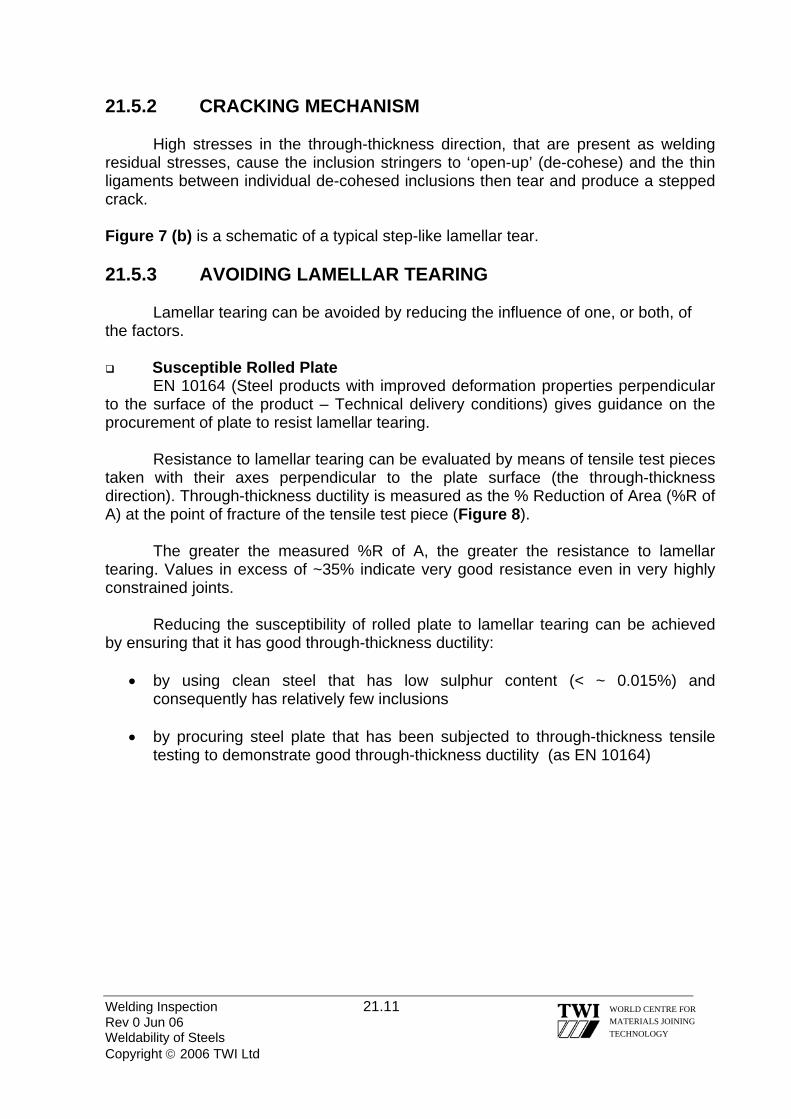
Welding Inspection 21.11 Rev 0 Jun 06 Weldability of Steels Copyright © 2006 TWI Ltd
WORLD CENTRE FOR MATERIALS JOINING TECHNOLOGY
21.5.2 CRACKING MECHANISM
High stresses in the through-thickness direction, that are present as welding residual stresses, cause the inclusion stringers to ‘open-up’ (de-cohese) and the thin ligaments between individual de-cohesed inclusions then tear and produce a stepped crack. Figure 7 (b) is a schematic of a typical step-like lamellar tear. 21.5.3 AVOIDING LAMELLAR TEARING
Lamellar tearing can be avoided by reducing the influence of one, or both, of the factors.
Susceptible Rolled Plate EN 10164 (Steel products with improved deformation properties perpendicular
to the surface of the product – Technical delivery conditions) gives guidance on the procurement of plate to resist lamellar tearing.
Resistance to lamellar tearing can be evaluated by means of tensile test pieces taken with their axes perpendicular to the plate surface (the through-thickness direction). Through-thickness ductility is measured as the % Reduction of Area (%R of A) at the point of fracture of the tensile test piece (Figure 8).
The greater the measured %R of A, the greater the resistance to lamellar tearing. Values in excess of ~35% indicate very good resistance even in very highly constrained joints.
Reducing the susceptibility of rolled plate to lamellar tearing can be achieved by ensuring that it has good through-thickness ductility:
• by using clean steel that has low sulphur content (< ~ 0.015%) and
consequently has relatively few inclusions • by procuring steel plate that has been subjected to through-thickness tensile
testing to demonstrate good through-thickness ductility (as EN 10164)

Welding Inspection 21.12 Rev 0 Jun 06 Weldability of Steels Copyright © 2006 TWI Ltd
WORLD CENTRE FOR MATERIALS JOINING TECHNOLOGY
Through-thickness Stress
Through thickness stress in T, K & Y joints is principally the residual stress from welding, although the additional service stress may have some influence.
Reducing the magnitude of through-thickness stresses for a particular weld joint would require modification to the joint, in some way, and so may not always be practical because of the need to satisfy design requirements. However, methods that could be considered are:
• reducing the size of the weld by:
• using a partial penetration butt weld instead of full-penetration
• using fillet welds instead of a full, or a partial pen. butt weld (Figure 9)
• by applying a buttering layer of weld metal to the surface of a susceptible plate so that the highest through-thickness strain is located in the weld metal and not the susceptible plate (Figure 10)
• changing the joint design – such as using a forged or extruded intermediate
piece so that the susceptible plate does not experience through-thickness stress(Figure 11)
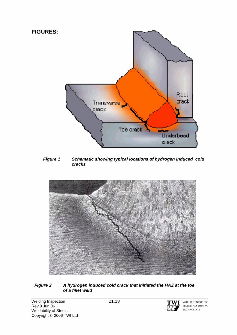
FIGURES:
Figure 1 Schematic showing typical locations of hydrogen induced cold cracks
Figure 2 A hydrogen induced cold crack that initiated the HAZ at the toe of a fillet weld
Welding Inspection 21.13 WORLD CENTRE FOR MATERIALS JOINING TECHNOLOGY
Rev 0 Jun 06 Weldability of Steels Copyright © 2006 TWI Ltd

X
Welding Inspection 21.14 Rev 0 Jun 06 Weldability of Steels Copyright © 2006 TWI Ltd
WORLD CENTRE FOR MATERIALS JOINING TECHNOLOGY
Figure 3 transverse
(a) Plan view of a plate butt weld showing subsurface cracks
(b) Longitudinal section X-Y of the above weld showing how the transverse cracks actually lie at 45° to the surface. They tend to remain within an individual weld run and may be in weld several layers. Their appearance in this orientation has given rise to the name ‘chevron’ cracks (arrow shaped cracks)
weld layers with cracks lying at 45°
to X-Y axis (b)
Y
transverse cracks (a)

Figure 4 (a) Solidification crack at the weld bean centre where columnar dendrites have trapped some lower melting
point liquid
(b) The weld bead does not have an ideal shape but it has solidified without the dendrites meeting ‘end-on’ and trapping lower melting point liquid thereby resisting solidification cracking
a
b
Welding Inspection 21.15 WORLD CENTRE FOR MATERIALS JOINING TECHNOLOGY
Rev 0 Jun 06 Weldability of Steels Copyright © 2006 TWI Ltd
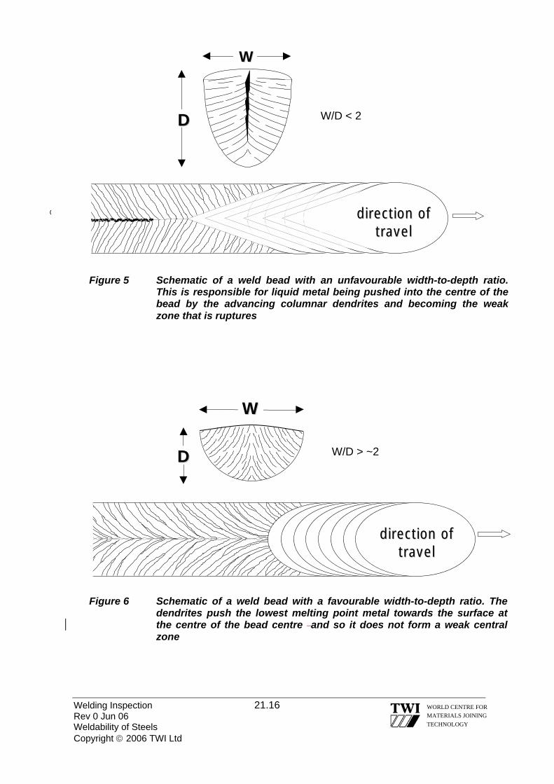
WW
Welding Inspection 21.16 Rev 0 Jun 06 Weldability of Steels Copyright © 2006 TWI Ltd
WORLD CENTRE FOR MATERIALS JOINING TECHNOLOGY
WW
DD
ddiirreeccttiioonn ooff ttrraavveell
‘Figure 6 Schematic of a weld bead with a favourable width-to-depth ratio. The dendrites push the lowest melting point metal towards the surface at the centre of the bead centre and so it does not form a weak central zone
W/D > ~2
DD W/D < 2
ddiirreeccttiioonn ooff ttrraavveell
(
Figure 5 Schematic of a weld bead with an unfavourable width-to-depth ratio. This is responsible for liquid metal being pushed into the centre of the bead by the advancing columnar dendrites and becoming the weak zone that is ruptures

Welding Inspection 21.17 Rev 0 Jun 06 Weldability of Steels Copyright © 2006 TWI Ltd
WORLD CENTRE FOR MATERIALS JOINING TECHNOLOGY
(a)
inclusion stringer
through-thickness residual stresses
from welding
de-cohesion of inclusion stringers
(b)
crack propagation by tearing of ligaments between ‘de-
cohesed’ inclusion stringers
Figure 7 (a) Typical lamellar tear located just outside the visible HAZ (b) Schematic of the step-like crack that is characteristic of a
lamellar tear
HAZ
fusion boundary
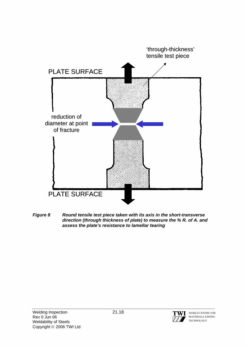
Welding Inspection 21.18 Rev 0 Jun 06 Weldability of Steels Copyright © 2006 TWI Ltd
WORLD CENTRE FOR MATERIALS JOINING TECHNOLOGY
PPLLAATTEE SSUURRFFAACCEE
PPLLAATTEE SSUURRFFAACCEE
‘‘tthhrroouugghh--tthhiicckknneessss’’ tteennssiillee tteesstt ppiieeccee
rreedduuccttiioonn ooff ddiiaammeetteerr aatt ppooiinntt
ooff ffrraaccttuurree
Figure 8 Round tensile test piece taken with its axis in the short-transverse direction (through thickness of plate) to measure the % R. of A. and assess the plate’s resistance to lamellar tearing

Welding Inspection 21.19 Rev 0 Jun 06 Weldability of Steels Copyright © 2006 TWI Ltd
WORLD CENTRE FOR MATERIALS JOINING TECHNOLOGY
susceptible plate susceptible plate
Figure 9 Reducing the effective size of a weld will reduce the through-thickness stress on the susceptible plate and may be sufficient to reduce the risk of lamellar tearing
extruded section susceptible plate
Figure 10 Lamellar tearing can be avoided by changing the joint design

weld metal ‘buttering’
susceptible plate
Figure 11 Two layers of weld metal (usually by MMA) applied to susceptible plate before the T-butt weld is made
Welding Inspection 21.20 WORLD CENTRE FOR MATERIALS JOINING TECHNOLOGY
Rev 0 Jun 06 Weldability of Steels Copyright © 2006 TWI Ltd

Welding Inspection Rev 0 Jun 06 Copyright © 2006, TWI Ltd
WORLD CENTRE FOR MATERIALS JOINING TECHNOLOGY
Section 22
Practical Visual Inspection

Welding Inspection 22.1 Rev 0 Jun 06 Practical Visual Inspection Copyright © 2006, TWI Ltd
WORLD CENTRE FOR MATERIALS JOINING TECHNOLOGY
22.0 PRACTICAL VISUAL INSPECTION The practical visual inspection part of the CSWIP examination consists of the following categories: CSWIP 3.0 VISUAL WELDING INSPECTOR Exam: Time allowed Practical butt-welded plate (code provided) 1 hour 45 minutes.
Practical fillet welded T joint (code provided) 1 hour 15 minutes.
CSWIP 3.1 WELDING INSPECTOR Exam: Time allowed Practical butt-welded plate (code provided) 1 hour 15 minutes.
Practical butt-welded pipe (candidates supplied code) 1 hour 45 minutes.
*Practical assessment of 2 macros (code provided) 45 minutes.
*Macro examination will be covered in another section
To successfully attempt the practical inspection elements of these examinations
the inspector will require a number of important tools: 1) Good eyesight. 2) Specialist Gauges. 3) Hand tools i.e. Magnifying glass, torch, mirror, graduated scale etc. 4) Pencil/pen, report forms, acceptance criteria, and a watch. GOOD EYESIGHT To effectively carry out your scope of work as a CSWIP qualified Welding Inspector it is important that you have a current eyesight certificate for close vision and a colour blindness test is also required. This must be provided before your CSWIP Welding Inspection examination. As per the CSWIP –WI-6-92 document.
All candidates for CSWIP examinations must be tested by a qualified optician.
Alternatively tests may be conducted; by qualified personnel available at most TWI examination centres.
Holders of CSWIP Welding Inspection certificates should thus make every effort to have their vision professionally tested twice yearly.
It is important to maintain this level of eyesight, NOTE! Your close vision ability
may decay over time.

SPECIALIST GAUGES A number of specialist gauges are available to measure the various elements that need to be measured in a welded fabrication including: a) Hi – Lo gauges, for measuring mismatch and root gap. b) Fillet weld profile gauges, for measuring fillet weld face profile and sizes. c) Angle gauges, for measuring weld preparation angles. d) Multi functional weld gauges, for measuring many different weld measurements.
Welding Inspection 22.2 Rev 0 Jun 06 Practical Visual Inspection Copyright © 2006, TWI Ltd
WORLD CENTRE FOR MATERIALS JOINING TECHNOLOGY
1
234
56
Hi-Lo gauge used to measure linear misalignment
Hi-Lo gauge can also be used to measure the root gap
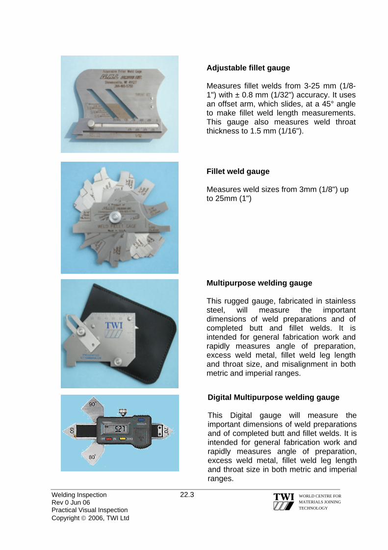
Welding Inspection 22.3 Rev 0 Jun 06 Practical Visual Inspection Copyright © 2006, TWI Ltd
WORLD CENTRE FOR MATERIALS JOINING TECHNOLOGY
Adjustable fillet gauge Measures fillet welds from 3-25 mm (1/8-1") with ± 0.8 mm (1/32") accuracy. It uses an offset arm, which slides, at a 45° angle to make fillet weld length measurements. This gauge also measures weld throat thickness to 1.5 mm (1/16").
Fillet weld gauge Measures weld sizes from 3mm (1/8") up to 25mm (1")
Multipurpose welding gauge This rugged gauge, fabricated in stainless steel, will measure the important dimensions of weld preparations and of completed butt and fillet welds. It is intended for general fabrication work and rapidly measures angle of preparation, excess weld metal, fillet weld leg length and throat size, and misalignment in both metric and imperial ranges.
Digital Multipurpose welding gauge
This Digital gauge will measure the important dimensions of weld preparations and of completed butt and fillet welds. It is intended for general fabrication work and rapidly measures angle of preparation, excess weld metal, fillet weld leg length and throat size in both metric and imperial ranges.

TWI CAMBRIDGE MULTI-PURPOSE WELDING GAUGE Angle of Preparation
This scale reads 00 to 600 in 50 steps. The angle is read against the chamfered edge of the plate, or pipe.
Linear Misalignment The gauge may be used to measure misalignment of members by placing the edge of the gauge on the lower member and rotating the segment until the pointed finger contacts the higher member.
Excess Weld Metal/Root penetration The scale is used to measure excess weld metal height or root penetration bead height of single sided butt welds, by placing the edge of the gauge on the plate and rotating the segment until the pointed finger contacts the excess weld metal or root bead at its highest point.
Pitting/mechanical damage etc The gauge may be used to measure defects by placing the edge of the gauge on the plate and rotating the segment until the pointed finger contacts the lowest depth. The reading is taken on the scale to the left of the zero mark in mm or inches.
Welding Inspection 22.4 Rev 0 Jun 06 Practical Visual Inspection Copyright © 2006, TWI Ltd
WORLD CENTRE FOR MATERIALS JOINING TECHNOLOGY

Fillet Weld Actual Throat Thickness
The small sliding pointer reads up to 20mm or ¾ inch. When measuring the throat it is supposed that the fillet weld has a ‘nominal’ design throat thickness, as an ‘effective’ design throat thickness cannot be measured in this manner.
Fillet Weld Leg Length The gauge may be used to measure fillet weld leg lengths of up to 25mm, as shown on left.
Excess weld metal can be easily calculated by measuring the Leg Length, and multiplying it by 0.7 This value is then subtracted from the measured Throat Thickness = Excess Weld Metal. Example: For a measured Leg Length of 10mm and Throat Thickness of 8 mm 10 x 0.7 = 7 ∴(Throat thickness 8) – 7 = 1 mm of Excess Weld Metal.
Welding Inspection 22.5 Rev 0 Jun 06 Practical Visual Inspection Copyright © 2006, TWI Ltd
WORLD CENTRE FOR MATERIALS JOINING TECHNOLOGY

FOR TRAINING PURPOSES ONLY
PLATE & FILLET ACCEPTANCE STANDARD TWI 1 KEY: L=Length. D=Depth or Height of defect. W=Width of defect (Applicable to inclusions only)
No Defect Name Remarks Maximum Allowed 1 Cracks Not Permitted 2 Porosity, Gas pores
Elongated gas Cavities (worm holes) Pipes
Max Dimension of any area or individual (as applicable)
1mm
3 Overlap Accumulative total for both defects shall not exceed 20mm
20mm in weld face length 4 Lack of side wall
fusion 5 Lack of root fusion Accumulative total for both
defects shall not exceed 20mm20mm in weld Root length
6 Lack of penetration
7 Inclusions (slag / silica etc)
Accumulative total shall not exceed 15mm total “L” in weld length (root & face independent)
Individual maximum L<12mm. W<3mm
8 Undercut 10%t up to a maximum D 1mm
9 Root concavity Maximum D 1mm 10 Underfill/incompletely
filled groove/lack of fill
Not permitted
11 Linear misalignment Maximum D <10mm t 1.0mm >10mm t 1.5mm
12 Arc strikes/Stray arc Not permitted 13 Mechanical damage Dependant on depth and blend Seek advice 14 Angular Misalignment Accept 15 Excess weld metal* Smooth transition is
required/All runs shall blend smoothly. No lack of interun fusion
2mm D maximum
16 Excess penetration* 1.5mm D maximum * When linear misalignment is present the following shall be applied.
Welding Inspection 22.6 Rev 0 Jun 06 Practical Visual Inspection Copyright © 2006, TWI Ltd
WORLD CENTRE FOR MATERIALS JOINING TECHNOLOGY

Excess weld metal Maximum height to be measured from a direct line from the “lowest plate”, across weldment Excess Penetration Maximum height to be measured from lowest plate
Welding Inspection 22.7 Rev 0 Jun 06 Practical Visual Inspection Copyright © 2006, TWI Ltd
WORLD CENTRE FOR MATERIALS JOINING TECHNOLOGY

Welding Inspection 22.8 Rev 0 Jun 06 Practical Visual Inspection Copyright © 2006, TWI Ltd
WORLD CENTRE FOR MATERIALS JOINING TECHNOLOGY
Pag
e 1
of 3
EXA
MPL
E P
LATE
REP
OR
T
N
ame:
[Blo
ck c
apita
ls]
STU
AR
T D
EN
T Si
gnat
ure:
S D
ENT
Tes
t pie
ce id
ent:
0
01
C
ode/
Spec
ifica
tion
used
: TW
I 09-
09-0
2
Wel
ding
pro
cess
: M
MA
/SM
AW
Jo
int t
ype:
S
ingl
e V
But
t
Wel
ding
pos
ition
: F
lat /
PA
Le
ngth
& th
ickn
ess
of p
late
: 3
00m
m x
10
mm
D
ate
8 N
ov 2
001
Und
ercu
t s
moo
th
1.5
max
236
Gas
por
e 1
.5 Ø
23
0
Lack
of s
idew
all f
usio
n
87
241
Exc
ess
wel
d m
etal
hei
ght :
4m
m.
Wel
d w
idth
: 12
-14m
m
Toe
blen
d: P
oor
Line
ar m
isal
ignm
ent:
2m
m
Spa
tter a
long
wel
d le
ngth
153
Und
erfil
l
51
Slag
inc
lusi
on
A
C
30 A
rc S
trik
e 40
WEL
D F
AC
E
8
22
M E A S U R E F R O M T H I S D A T U M E D G E

Welding Inspection 22.9 Rev 0 Jun 06 Practical Visual Inspection Copyright © 2006, TWI Ltd
WORLD CENTRE FOR MATERIALS JOINING TECHNOLOGY
WEL
D R
OO
T A
C
Lack
of r
oot f
usio
n
247
Lack
of p
enet
ratio
n
128
Roo
t con
cavi
ty
2
dee
p C
lust
er p
oros
ity
<
1.0m
m ∅
23
Pen
etra
tion
heig
ht: 4
mm
max
Pen
etra
tion
wid
th:
3 –
6mm
To
e bl
end:
sm
ooth
Line
ar m
isal
ignm
ent:
2mm
10
50
20
10
113
M E A S U R E F R O M T H I S D A T U M E D G E
Pag
e 2
of 3
EX
AM
PLE
PLA
TE R
EPO
RT

Page 3 of 3 age 3 of 3 SENTENCE SHEET for PIPE/PLATE INSPECTION REPORT SENTENCE SHEET for PIPE/PLATE INSPECTION REPORT PRINT FULL NAME S.DENT PRINT FULL NAME S.DENT SPECIMEN NUMBER 001 SPECIMEN NUMBER 001
FACE IMPERFECTIONS FACE IMPERFECTIONS Imperfections
Reported Imperfections
Reported Code or Specification
Reference Code or Specification
Reference Sentence Sentence
Imperfection Types
Maximum Value or Total Length
1
Maximum Allowed by Code
2
Code Section or Table No
3
Accept or Reject
4 4
Excess Weld Metal (Height) 4mm 2mm 15 Reject Toe blend / inter-run blend Poor/uneven Smooth 15 Reject Incomplete filling 40mm None 10 Reject Slag Inclusions 8mm 15mm 7 Accept Undercut 1.5mm deep 10%t Max 1mm 8 Reject Surface Porosity None _________ _______ Accept Cracks None _________ _______ Accept Lack of fusion 87mm 20mm 4 Reject Arc strikes 3 None Reject? Mechanical damage Grinding mark Seek Advice 13 Refer ? Misalignment 2mm 1.5mm 11 Reject
ROOT IMPERFECTIONS
Misalignment 2mm 1.5mm 11 Reject Penetration (Height) 4mm 1.5mm 16 Reject Lack of Root Penetration 50mm 20mm 6 Reject Lack of Root Fusion 20mm 20mm 5 Reject Root Concavity 10mm L 2mm 10%t Max 1mm 8 Reject Root Undercut None _________ _______ Accept Cracks None _________ _______ Accept Porosity Cluster <1mm Max 1mm ∅ 2 Accept Burn through None N/A NA Accept
This pipe/plate* has been examined to the requirements of [code/specification] TWI 1 and is accepted/rejected* accordingly. [*Delete whichever is not applicable]
Signature. S DENT Date.00/00/0000. Comments:.
Welding Inspection 22.10 Rev 0 Jun 06 Practical Visual Inspection Copyright © 2006, TWI Ltd
WORLD CENTRE FOR MATERIALS JOINING TECHNOLOGY
Welding Inspection Rev 0 Jun 06 Copyright © 2006, TWI Ltd
WORLD CENTRE FOR MATERIALS JOINING TECHNOLOGY
Section 23
Application & Control of Preheat
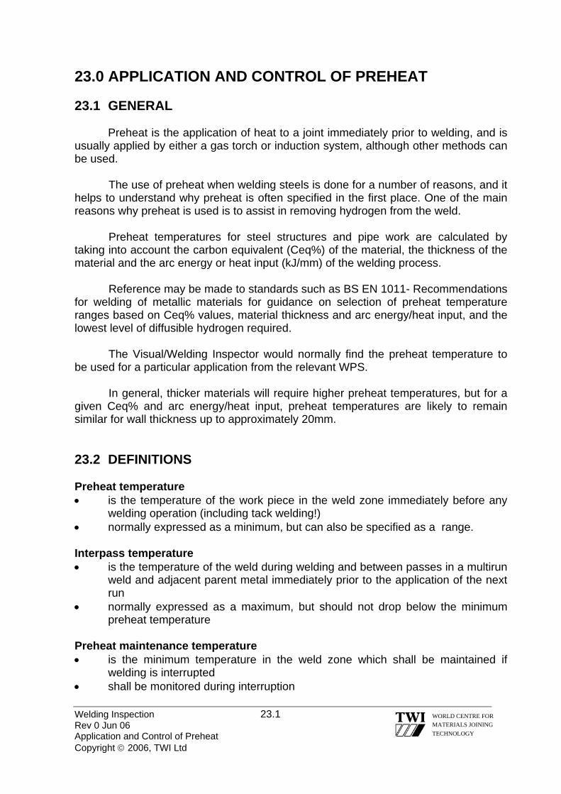
Welding Inspection 23.1 Rev 0 Jun 06 Application and Control of Preheat Copyright © 2006, TWI Ltd
WORLD CENTRE FOR MATERIALS JOINING TECHNOLOGY
23.0 APPLICATION AND CONTROL OF PREHEAT 23.1 GENERAL Preheat is the application of heat to a joint immediately prior to welding, and is usually applied by either a gas torch or induction system, although other methods can be used.
The use of preheat when welding steels is done for a number of reasons, and it helps to understand why preheat is often specified in the first place. One of the main reasons why preheat is used is to assist in removing hydrogen from the weld.
Preheat temperatures for steel structures and pipe work are calculated by taking into account the carbon equivalent (Ceq%) of the material, the thickness of the material and the arc energy or heat input (kJ/mm) of the welding process.
Reference may be made to standards such as BS EN 1011- Recommendations for welding of metallic materials for guidance on selection of preheat temperature ranges based on Ceq% values, material thickness and arc energy/heat input, and the lowest level of diffusible hydrogen required.
The Visual/Welding Inspector would normally find the preheat temperature to be used for a particular application from the relevant WPS.
In general, thicker materials will require higher preheat temperatures, but for a given Ceq% and arc energy/heat input, preheat temperatures are likely to remain similar for wall thickness up to approximately 20mm. 23.2 DEFINITIONS Preheat temperature • is the temperature of the work piece in the weld zone immediately before any
welding operation (including tack welding!) • normally expressed as a minimum, but can also be specified as a range. Interpass temperature • is the temperature of the weld during welding and between passes in a multirun
weld and adjacent parent metal immediately prior to the application of the next run
• normally expressed as a maximum, but should not drop below the minimum preheat temperature
Preheat maintenance temperature • is the minimum temperature in the weld zone which shall be maintained if
welding is interrupted • shall be monitored during interruption

23.3 APPLICATION OF PREHEAT Local Global
Welding Inspection 23.2 Rev 0 Jun 06 Application and Control of Preheat Copyright © 2006, TWI Ltd
WORLD CENTRE FOR MATERIALS JOINING TECHNOLOGY
Preheat
• Less energy required • Possible stresses due
to non-uniform
• More energy required • Uniform heating – no
additional stresses
HF heating elements
Resistive heating elements
Gas/electric oven
Flame Applied Pre heat

Welding Inspection 23.3 Rev 0 Jun 06 Application and Control of Preheat Copyright © 2006, TWI Ltd
WORLD CENTRE FOR MATERIALS JOINING TECHNOLOGY
Gas/Electric Ovens Generally used for PWHT but can be used for large sections of material to give a controlled and uniform preheat. Resistive Heating Elements A method of heating using electric current flowing through resistance coils. High Frequency Heating Elements A process in which the heating effect is produced electrostatically, providing uniform heating through a mass of material. Heat is generated by the agitation of the molecules in the material when subjected to a high frequency field. Flame Applied Pre Heat. Probably the most common method of applying preheat which can be applied by either torches or burners. Oxygen is an essential part of the preheating flame, as it supports combustion, but the fuel gases can be, acetylene, propane and methane (natural gas). With flame applied preheating sufficient time must be allowed for the temperature to equalise throughout the thickness of the components to be welded. Otherwise only the surface temperature will be measured. The time lapse will vary depending on the specification requirements. 23.4 CONTROL OF PREHEAT AND INTERPASS TEMPERATURE When? Immediately before passage of the arc

Where?
Work piece thickness (t)
t ≤ 50 mm t > 50 mm
• A = 4 x t but max. 50 mm • A = min. 75 mm • where practicable, the
temperature shall be measured on the face opposite to that being heated
• allow 2 min per every 25 mm of parent metal thickness for temperature equalisation
• the temperature shall be measured on the surface of the work piece facing the welder
Interpass temperature shall be measured on the weld metal or the immediately adjacent parent metal
Welding Inspection 23.4 Rev 0 Jun 06 Application and Control of Preheat Copyright © 2006, TWI Ltd
WORLD CENTRE FOR MATERIALS JOINING TECHNOLOGY

Why? Applying preheat has the following advantages: • It slows down the cooling rate of the weld and HAZ; reducing the risk of
hardened microstructures forming; allowing absorbed hydrogen more opportunity of diffusing out, thus reducing the potential for cracking.
• Removes moisture from the region of the weld preparation. • Improves overall fusion characteristics during welding. • Ensures more uniform expansion and contraction; lowering stresses between
weld and parent material
Welding Inspection 23.5 Rev 0 Jun 06 Application and Control of Preheat Copyright © 2006, TWI Ltd
WORLD CENTRE FOR MATERIALS JOINING TECHNOLOGY
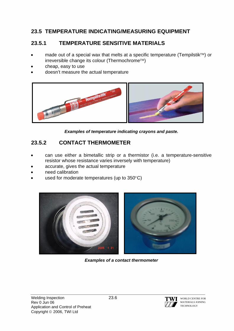
23.5 TEMPERATURE INDICATING/MEASURING EQUIPMENT 23.5.1 TEMPERATURE SENSITIVE MATERIALS • made out of a special wax that melts at a specific temperature (Tempilstik™) or
irreversible change its colour (Thermochrome™) • cheap, easy to use • doesn’t measure the actual temperature
Examples of temperature indicating crayons and paste.
23.5.2 CONTACT THERMOMETER • can use either a bimetallic strip or a thermistor (i.e. a temperature-sensitive
resistor whose resistance varies inversely with temperature) • accurate, gives the actual temperature • need calibration • used for moderate temperatures (up to 350°C)
Examples of a contact thermometer
Welding Inspection 23.6 Rev 0 Jun 06 Application and Control of Preheat Copyright © 2006, TWI Ltd
WORLD CENTRE FOR MATERIALS JOINING TECHNOLOGY

23.5.3 THERMOCOUPLE • based on measuring the thermoelectric potential difference between a hot
junction (placed on the weld) and a cold junction (reference junction) • measures over a wide range of temperatures • accurate, gives the actual temperature • can be used also for continuous monitoring • need calibration
Examples of thermocouples
23.5.4 OPTICAL OR ELECTRICAL DEVICES FOR CONTACTLESS
MEASUREMENT • can be infrared or optical pyrometers • measure the radiant energy emitted by the hot body • contactless method mean it can be used for remote measurements • very complex and expensive equipment • normally used for measuring high temperatures
Example of contactless temperature measuring equipment
Welding Inspection 23.7 Rev 0 Jun 06 Application and Control of Preheat Copyright © 2006, TWI Ltd
WORLD CENTRE FOR MATERIALS JOINING TECHNOLOGY

Welding Inspection 23.8 Rev 0 Jun 06 Application and Control of Preheat Copyright © 2006, TWI Ltd
WORLD CENTRE FOR MATERIALS JOINING TECHNOLOGY
23.6 SUMMARY
The Visual/Welding Inspector should refer to the WPS for both preheat and interpass temperature requirements. If in any doubt as to where the temperature measurements are to be taken, the Senior Welding Inspector or Welding Engineer should be consulted for guidance.
Both preheat and interpass temperatures are applied to slow down the cooling rate during welding, avoiding the formation of brittle microstructures (i.e. Martensite) and thus preventing cold cracking.
Preheat temperatures can be calculated using different methods as described in various standards (e.g. BS EN 1011-2, AWS D1.1, etc) and are validated during the qualification of the welding procedure
According to BS EN ISO 15614 and ASME IX both preheat and interpass temperatures are considered to be essential variables, hence any change outside the range of qualification requires a new procedure qualification.

Welding Inspection Rev 0 Jun 06 Copyright © 2006, TWI Ltd
WORLD CENTRE FOR MATERIALS JOINING TECHNOLOGY
Section 24
Calibration of Welding Equipment

Welding Inspection 24.1 Rev 0 Jun 06 Calibration of Welding Equipment Copyright © 2006, TWI Ltd
WORLD CENTRE FOR MATERIALS JOINING TECHNOLOGY
24.0 CALIBRATION OF WELDING EQUIPMENT 24.1 INTRODUCTION
BS 7570 - Code of practice for validation of arc welding equipment – is a standard that gives guidance: to manufacturers about the accuracy required from output meters fitted to welding
equipment to show welding current, voltage etc to end users who need to ensure that he output meters provide accurate readings
The Standard refers to two grades of equipment - Standard Grade and
Precision Grade.
Standard Grade equipment is suitable for manual and semi-automatic welding processes.
Precision Grade equipment is intended for mechanised or automatic welding because of there is usually a need for greater precision for all welding variables as well as the prospect of equipment it being used for higher ‘duty cycle’ welding. 24.2 TERMINOLOGY BS 7570 defines the terms it uses - such as:
Calibration operations for the purpose of determining the magnitude of errors of a measuring instrument ……………etc
Validation operations for the purpose of demonstrating that an item of
welding equipment, or a welding system, conforms to the operating specification for that equipment or system
Accuracy closeness of an observed quantity to the defined, or true, value
Thus, when considering welding equipment, those that have output meters for
welding parameters (current, voltage, travel speed etc.) can be calibrated by checking the meter reading with a more accurate measuring device – and adjusting the readings appropriately.
Equipment that does not have output meters (some power sources for MMA, MIG/MAG) cannot be ‘calibrated’ but they can be validated, that is to make checks to see that the controls are functioning properly.

Welding Inspection 24.2 Rev 0 Jun 06 Calibration of Welding Equipment Copyright © 2006, TWI Ltd
WORLD CENTRE FOR MATERIALS JOINING TECHNOLOGY
24.3 CALIBRATION FREQUENCY BS 7570 recommends re-calibration/validation: - at yearly intervals (following an initial consistency test at 3 month intervals) for
Standard Grade equipment at 6 monthly intervals for Precision Grade equipment.
However, the Standard also recommends that re-calibration/validation may be
necessary at more frequently. Factors that need to be considered are: - the equipment manufacturer’s recommendations
the user’s requirements
if the equipment has been repaired re-calibration should always be carried out
there is reason to believe the performance of the equipment has deteriorated
24.4 INSTRUMENTS FOR CALIBRATION Instruments used for calibration should: be calibrated by a recognised calibrator - using standards that are traceable to
a national standard be at least twice, and preferably five times, more accurate than the accuracy
required for the Grade of equipment
for Precision Grade equipment it will be necessary to use instruments with much greater precision for checking output meters
24.5 CALIBRATION METHODS
The Standard gives details about the characteristics of power source types, how many readings should be taken for each parameter and guidance on precautions that may be necessary.

Welding Inspection 24.3 Rev 0 Jun 06 Calibration of Welding Equipment Copyright © 2006, TWI Ltd
WORLD CENTRE FOR MATERIALS JOINING TECHNOLOGY
For the main welding parameters, recommendations from the Standard are as follows:
Current Details are given about the instrumentation requirements and how to measure
pulsed current but there are requirements given specified, or recommendations made, about where in the circuit current measurements should be made.
The implication is that current can be measured at any position in the circuit –
the value should be the same.
Voltage The standard emphasises that for processes where voltage is pre-set (on
constant voltage the power sources) the connection points used for the voltmeter incorporated into the power source may differ from the arc voltage, which is the important parameter.
To obtain an accurate measure of arc voltage, the voltmeter should positioned
as near as practical to the arc.
This is illustrated by the figure in the end of this section, which shows the power source voltage meter connected across points 1 & 7.
However, because there will be some voltage drops in sections 1 – 2, 3 – 4 & 6 – 7 due to connection points introducing extra resistance into the circuit, the voltage meter reading on the power source will tend to give a higher reading than the true arc voltage.
Even if the power source voltmeter is connected across points 3 & 7 (which it may be) the meter reading would not take account of any significant voltage drops in the return cable - section 6 – 7.
The magnitude of any voltage drops in the welding circuit will depend on cable diameter, cable length and temperature of the cable and the Standard emphasises the following: - it is desirable to measure the true arc voltage between points 4 – 5 but for
some welding processes it is not practical to measure arc voltage so close to the arc
for MMA, it is possible to take a voltage reading relatively close to the arc by
connecting one terminal of the voltmeter through the cable sheath as close as ~ 2m from the arc and connect the other terminal to the workpiece (or to earth)
for MIG/MAG the nearest practical connection points have to be 3 – 5 but a
change from an air-cooled torch to a water-cooled torch or vice-versa may have a significant affect on the measured voltage

Welding Inspection 24.4 Rev 0 Jun 06 Calibration of Welding Equipment Copyright © 2006, TWI Ltd
WORLD CENTRE FOR MATERIALS JOINING TECHNOLOGY
voltage drops between points 5 – 6 will be insignificant if there is a good
connection of the return cable at point 6.
The Standard gives guidance about minimising any drop in line voltage by ensuring that: the current return cable is as short as practical and is ‘heavy’, low resistance,
cable the current-return connector is suitably ‘rated’ and is firmly attached and so
does not overheat due to high resistance The standard gives data for line voltage drops (DC voltage) according to current, cable cross section and cable length (for both copper & aluminium cables).
Wire Feed Speed For constant voltage (self-adjusting arc) processes such as MIG/MAG the
standard recognises that calibration of the wire feeder is generally not needed because it is linked to current.
If calibration is required, it is recommended that the time be measured (in
seconds) for ~1m of wire to be delivered (using a stopwatch or an electronic timer).
The length of wire should then be measured (with a steel rule) to an accuracy
of 1mm and the feed speed calculated.
Travel Speed Welding manipulators, such as rotators and robotic manipulators, as well as the
more conventional linear travel carriages, influence heat input and other properties of a weld and should be checked at intervals.
Most of the standard devices can be checked using a stopwatch and measuring
rule, but more sophisticated equipment, such as a tacho-generator, may be appropriate.

Power Source
Welding Inspection 24.5 Rev 0 Jun 06 Calibration of Welding Equipment Copyright © 2006, TWI Ltd
WORLD CENTRE FOR MATERIALS JOINING TECHNOLOGY
Wire Feeder 1 7
{ arc 4
5
3 2
6
An example of a welding circuit (for MIG/MAG)

Welding Inspection Rev 0 Jun 06 Copyright © 2006, TWI Ltd
WORLD CENTRE FOR MATERIALS JOINING TECHNOLOGY
Section 25
Macro / Micro Examination

Welding Inspection 25.1 Rev 0 Jun 06 Macro / Micro Examination Copyright © 2006, TWI Ltd
WORLD CENTRE FOR MATERIALS JOINING TECHNOLOGY
25.0 MACRO / MICRO EXAMINATION 25.1 MACRO EXAMINATION Macroetching is the procedure in which a specimen is etched and evaluated macrostructurally at low magnifications. It is a frequently used technique for evaluating steel products such as billets, bars, blooms, and forgings as well as welds. There are several procedures for rating a steel specimen by a graded series of photographs showing the incidence of certain conditions and is applicable to carbon and low alloy steels. A number of different etching reagents may be used depending upon the type of examination to be made. Steels react differently to etching reagents because of variations in chemical composition, method of manufacturing, heat treatment and many other variables. Macro-Examinations are also performed on a polished and etched cross-section of a welded material. During the examination, a number of features can be determined including weld run sequence, important for weld procedure qualifications tests. As well as this, any defects on the sample will be assessed for compliance with relevant specifications. Slag, porosity, lack of weld penetration, lack of sidewall fusion and poor weld profile are among the features observed in such examinations. It is normal to look for such defects either by standard visual examination or at magnifications of up to 5X. It is also routine to photograph the section to provide a permanent record. This is known as a photomacrograph. 25.2 MICRO EXAMINATION This is performed on samples either cut to size or mounted in a resin mold. The samples are polished to a fine finish, normally one-micron diamond paste, and usually etched in an appropriate chemical solution prior to examination on a metallurgical microscope. Micro-examination is performed for a number of purposes, the most obvious of which is to assess the structure of the material. It is also common to examine for metallurgical anomalies such as third phase precipitates, excessive grain growth, etc. Many routine tests such as phase counting or grain size determinations are performed in conjunction with micro-examinations. Metallographic weld evaluations can take many forms. In its most simple form, a weld deposit can be visually examined for large-scale defects such as porosity or lack of fusion defects. On a micro scale, the examination can take the form of phase balance assessments from weld cap to weld root or a check for non-metallic or third phase precipitates. Examination of weld growth patterns is also used to determine reasons for poor mechanical test results. For example, an extensive central columnar grain pattern can cause a plane of weakness giving poor Charpy results.
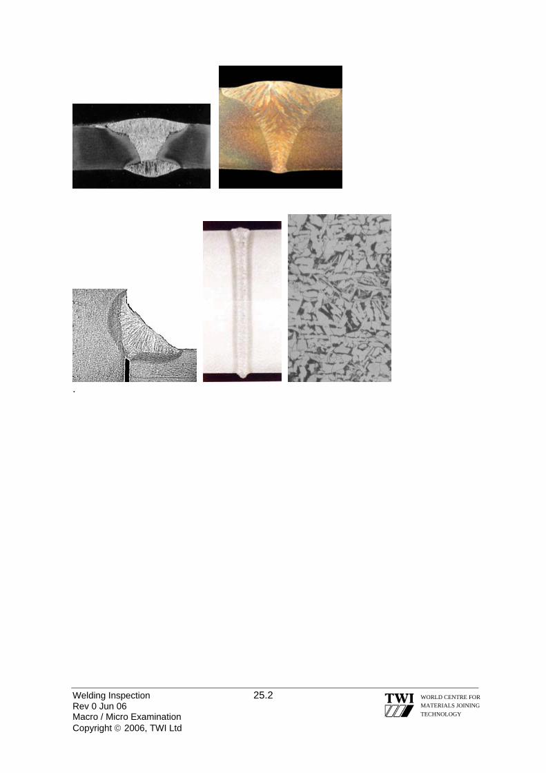
.
Welding Inspection 25.2 Rev 0 Jun 06 Macro / Micro Examination Copyright © 2006, TWI Ltd
WORLD CENTRE FOR MATERIALS JOINING TECHNOLOGY
Welding Inspection Rev 0 Jun 06 Copyright © 2006, TWI Ltd
WORLD CENTRE FOR MATERIALS JOINING TECHNOLOGY
Section 26
Appendix

Page 1 of 5 VISUAL INSPECTION PLATE REPORT
Name [Block capitals]__________________________ Signature ___________________________ Test piece identification Code/Specification used ________________________ Welding process _____________________ Joint type__________________ Welding position __________ Length & thickness of plate ___________ Date
A M E A S U R E F R O M T H I S D A T U M E D G E
B
WELD FACE
C

Page 2 of 5
VISUAL PLATE REPORT
PART THREE – DEFECT ASSESSMENT FORM
ME A S U R E F R O M T H I S D A T U M O N L Y
A
WELD ROOT
B C

Page 3 of 5 VISUAL INSPECTION PIPE REPORT
Name [Block capitals]_____________________ Signature_________________ Pipe Ident#___________ Code/Specification used____________________Welding Process__________ Joint type____________ Welding position____________________ Outside ∅ & Thickness________ Date ________________
WELD FACE
B A C
D A C
P.T.O. [ FOR ROOT]
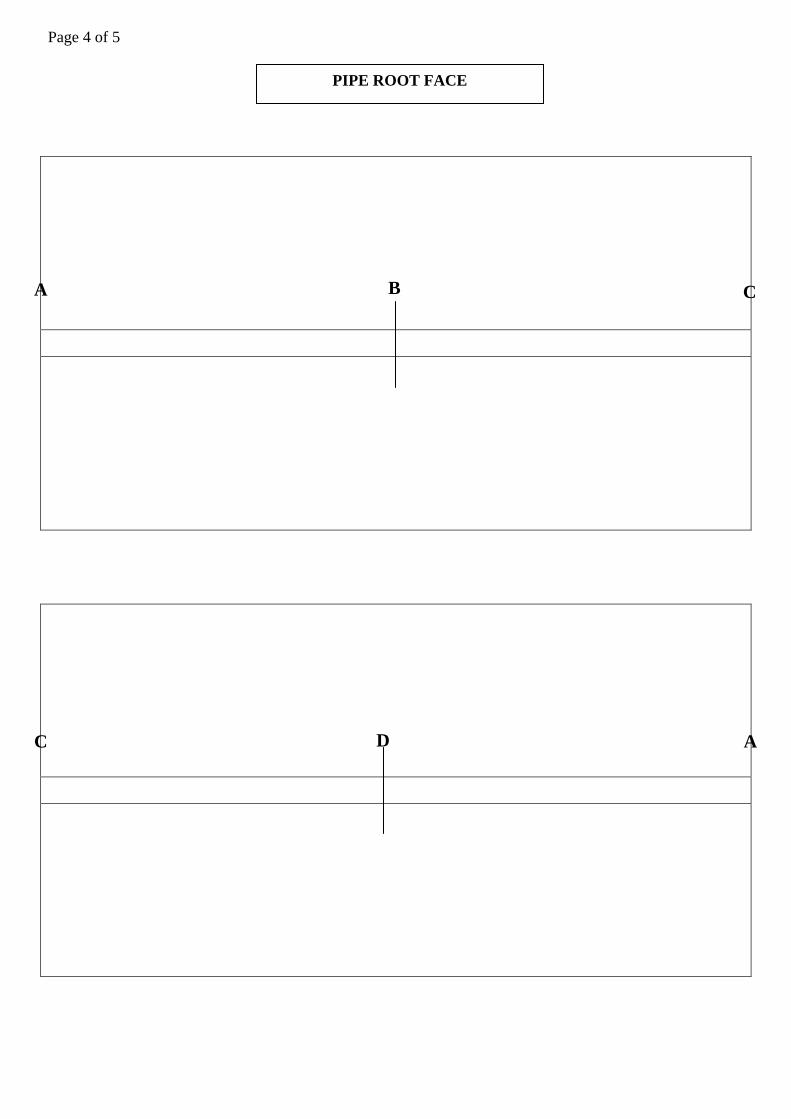
Page 4 of 5 PIPE ROOT FACE
B A C
D A C
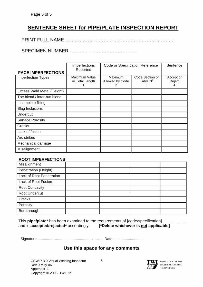
Page 5 of 5
CSWIP 3.0 Visual Welding Inspector 5 Rev 0 May 06 Appendix 1 Copyright © 2006, TWI Ltd
WORLD CENTRE FOR MATERIALS JOINING TECHNOLOGY
SENTENCE SHEET for PIPE/PLATE INSPECTION REPORT
PRINT FULL NAME ………………………………………………………….. SPECIMEN NUMBER ……………………………………
FACE IMPERFECTIONS
Imperfections Reported
Code or Specification Reference Sentence
Imperfection Types
Maximum Value or Total Length
1
Maximum Allowed by Code
2
Code Section or Table No
3
Accept or Reject
4
Excess Weld Metal (Height) Toe blend / inter-run blend Incomplete filling Slag Inclusions Undercut Surface Porosity Cracks Lack of fusion Arc strikes Mechanical damage Misalignment
ROOT IMPERFECTIONS
Misalignment Penetration (Height) Lack of Root Penetration Lack of Root Fusion Root Concavity Root Undercut Cracks Porosity Burnthrough
This pipe/plate* has been examined to the requirements of [code/specification] .............…... and is accepted/rejected* accordingly. [*Delete whichever is not applicable]
Signature..............….................................…….… Date...............................
Use this space for any comments
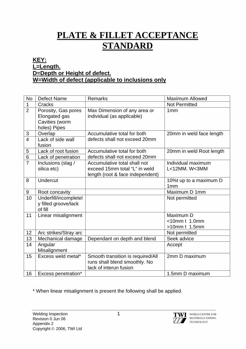
Welding Inspection 1 Revision 0 Jun 06 Appendix 2 Copyright © 2006, TWI Ltd
WORLD CENTRE FOR MATERIALS JOINING TECHNOLOGY
PLATE & FILLET ACCEPTANCE STANDARD
KEY: L=Length. D=Depth or Height of defect. W=Width of defect (applicable to inclusions only
No Defect Name Remarks Maximum Allowed 1 Cracks Not Permitted 2 Porosity, Gas pores
Elongated gas Cavities (worm holes) Pipes
Max Dimension of any area or individual (as applicable)
1mm
3 Overlap Accumulative total for both defects shall not exceed 20mm
20mm in weld face length 4 Lack of side wall
fusion 5 Lack of root fusion Accumulative total for both
defects shall not exceed 20mm 20mm in weld Root length 6 Lack of penetration
7 Inclusions (slag / silica etc)
Accumulative total shall not exceed 15mm total “L” in weld length (root & face independent)
Individual maximum L<12MM. W<3MM
8 Undercut 10%t up to a maximum D 1mm
9 Root concavity Maximum D 1mm 10 Underfill/incompletel
y filled groove/lack of fill
Not permitted
11 Linear misalignment Maximum D <10mm t 1.0mm >10mm t 1.5mm
12 Arc strikes/Stray arc Not permitted 13 Mechanical damage Dependant on depth and blend Seek advice 14 Angular
Misalignment Accept
15 Excess weld metal* Smooth transition is required/All runs shall blend smoothly. No lack of interun fusion
2mm D maximum
16 Excess penetration* 1.5mm D maximum * When linear misalignment is present the following shall be applied.

Excess weld metal Maximum height to be measured from a direct line from the “lowest plate”, across weldment Excess Penetration Maximum height to be measured from lowest plate
Welding Inspection 2 WORLD CENTRE FOR MATERIALS JOINING TECHNOLOGY
Revision 0 Jun 06 Appendix 2 Copyright © 2006, TWI Ltd

WORLD CENTRE FOR MATERIALS JOINING TECHNOLOGY
Contact us for information on our wide range of courses at: TWI Training & Examination Services Granta Park Gt Abington Cambridge CB1 6AL, UK Tel: +44 (0)1223 899000 Fax: +44 (0)1223 891630 Email: [email protected]
TWI Technology Centre (North East) Aurora Court Barton Road Riverside Park Middlesbrough TS2 1RY, UK Tel: +44 (0)1642 210512 Fax: +44 (0)1642 252218 Email: [email protected]
TWI Technology Centre (Yorkshire) Ltd Wallis Way Catcliffe Rotherham S60 5TZ, UK Tel: +44 (0)114 2699046 Fax: +44 (0)114 2699781 Email: [email protected]
TWI Technology Centre (Wales) ECM2
Heol Cefn Gwrgan Margam Port Talbot SA13 2EZ, UK Tel: +44 (0)1639 873100 Fax: +44 (0)1639 864679 Email: [email protected]
TWI Training & Certification (SE Asia) No. 8 Jalan TSB 10 Sg Buloh Ind. Park 47000 Sg Buloh Selangor Darul Ehsan Malaysia Tel. : 603-61573526/28 Fax : 603-61572378 EMail : [email protected]
TWI Training & Examination Services P O Box 52721 Abu Dhabi Tel: +971 2 6270750 Fax: +971 2 6270424 Email: [email protected]