css 372 - lecture 2 chapter 3 – connecting computer components with buses bus structures...
Post on 22-Dec-2015
218 views
TRANSCRIPT

CSS 372 - Lecture 2CSS 372 - Lecture 2
Chapter 3 – Connecting Computer Components with Buses
Bus Structures
Synchronous, Asynchronous
Typical Bus Signals
Two level, Tri-state, Wired Or
Hierarchical Bus Organizations
PCI Bus Example
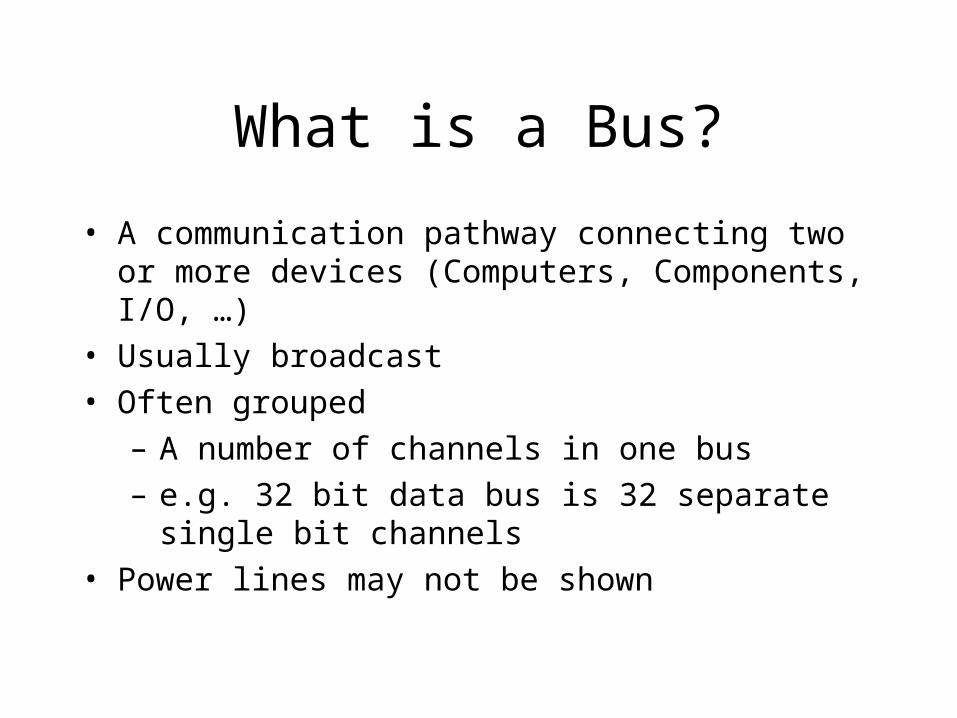
What is a Bus?
• A communication pathway connecting two or more devices (Computers, Components, I/O, …)
• Usually broadcast
• Often grouped
– A number of channels in one bus
– e.g. 32 bit data bus is 32 separate single bit channels
• Power lines may not be shown

What do Buses look like?
– Parallel lines on circuit boards– Ribbon cables– Strip connectors on mother boards– Sets of wires

Types of Buses
• Synchronous• Asynchronous (Hand Shaking)
• Serial (Twisted pair, Coaxial Cable, ..)• Parallel (Ribbon Cable,

Types of Buses
• Dedicated– Separate data & address lines
• Multiplexed– Shared lines
– Address valid or data valid control line
– Advantage - fewer lines
– Disadvantages• More complex control
• Ultimate performance

Physical Considerations for Buses• Media (voltage, optic)
• Signal levels – the higher, the more immune to noise
• Noise Absorption – wires can pick up noise from neighboring wires
• Noise Generation – wires can be antennas
• Length Creates Delay ( reduces Bandwidth) Consumes Power Creates reflections – (Terminations become more critical)

Logic Threshold Voltage Levels

Signal Scheme Alternatives
• Totempole - High or Low output level Line always at a 1 level or 0 level
• Open collector, open drain, wired-or Line is nominally at a 1 level or 0 level – line is “pulled” to non-nominal level
• Tristate Has third state – open
• Differential Uses a pair of lines – the level is the difference of signals on the two lines.

Bus Challenges
• Lots of devices on one bus leads to:– Propagation delays
• Long data paths mean that co-ordination of bus use can adversely affect performance
– Traffic congestion• Too many devices communicating reduces bandwidth
• Alternative - Systems use multiple buses

Simple Computer Bus
++ clock(s), power(s), and ground(SS)
Notes: 1) Bus lines need to be properly terminated
2) Power lines are to furnish reference voltage, not power
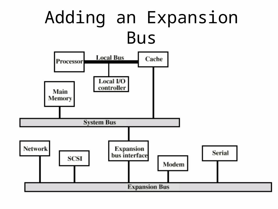
Adding an Expansion Bus
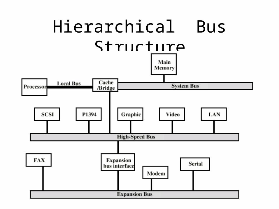
Hierarchical Bus Structure
Bus Arbitration
• More than one module may need to control the bus
e.g. CPUs and DMA controller
• Only one module may control the bus at one time
• Arbitration may be centralised or distributed

Centralised or Distributed Arbitration
• Centralised– Single hardware device controlling bus access
• Bus Controller• Arbiter
– May be part of CPU or separate
• Distributed– More than one module may claim the bus Need control logic on all these modules
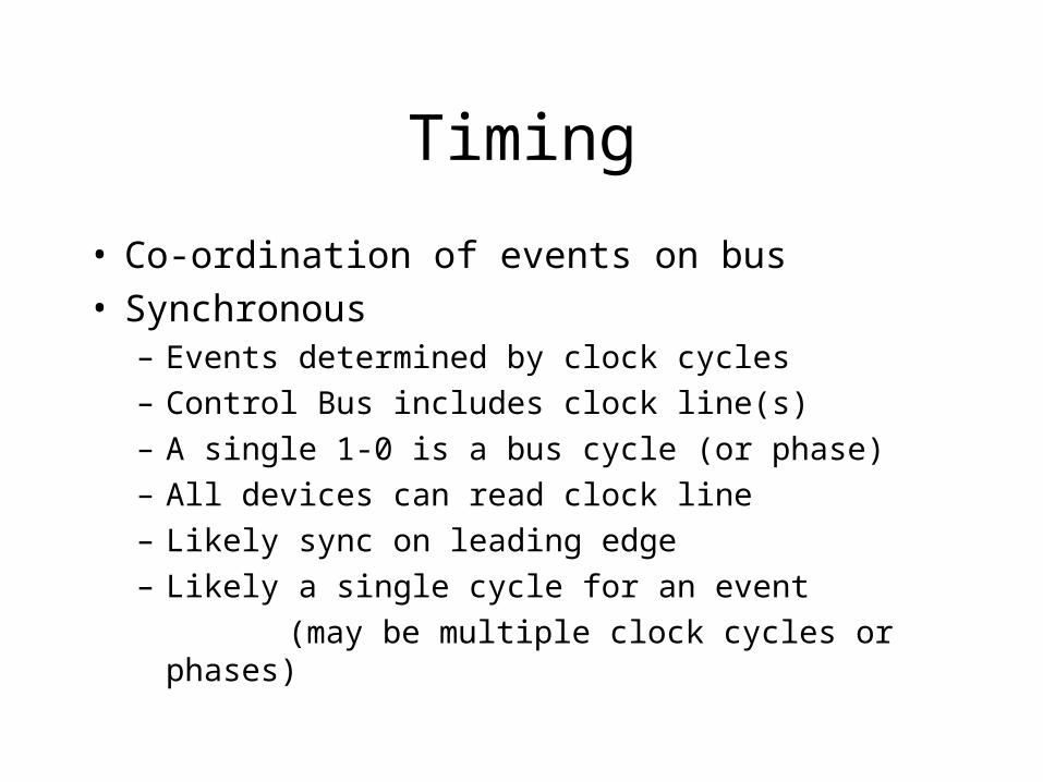
Timing
• Co-ordination of events on bus• Synchronous
– Events determined by clock cycles
– Control Bus includes clock line(s)
– A single 1-0 is a bus cycle (or phase)
– All devices can read clock line
– Likely sync on leading edge
– Likely a single cycle for an event
(may be multiple clock cycles or phases)
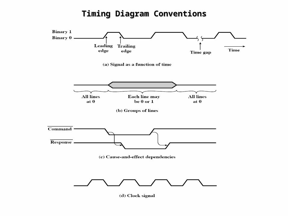
Timing Diagram ConventionsTiming Diagram Conventions
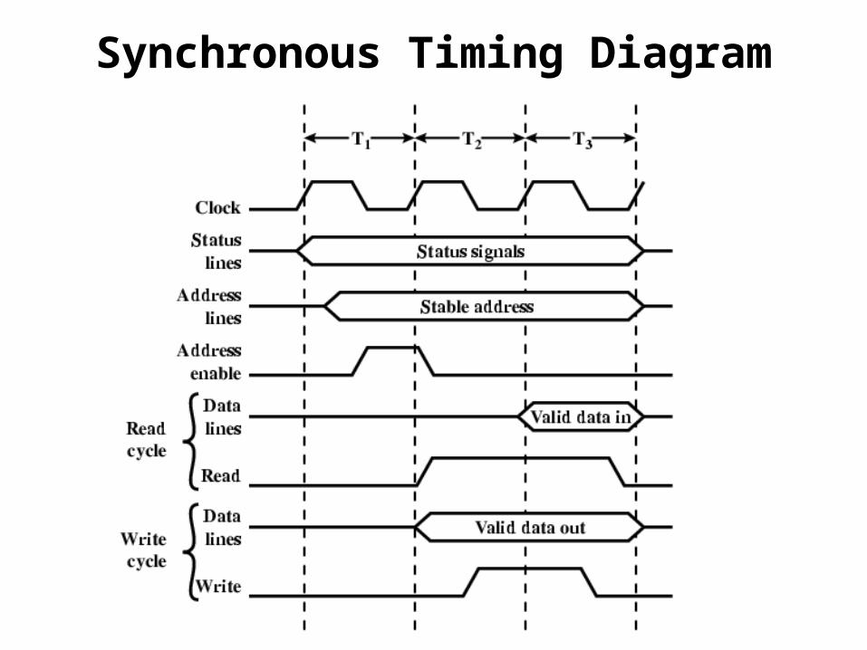
Synchronous Timing Diagram
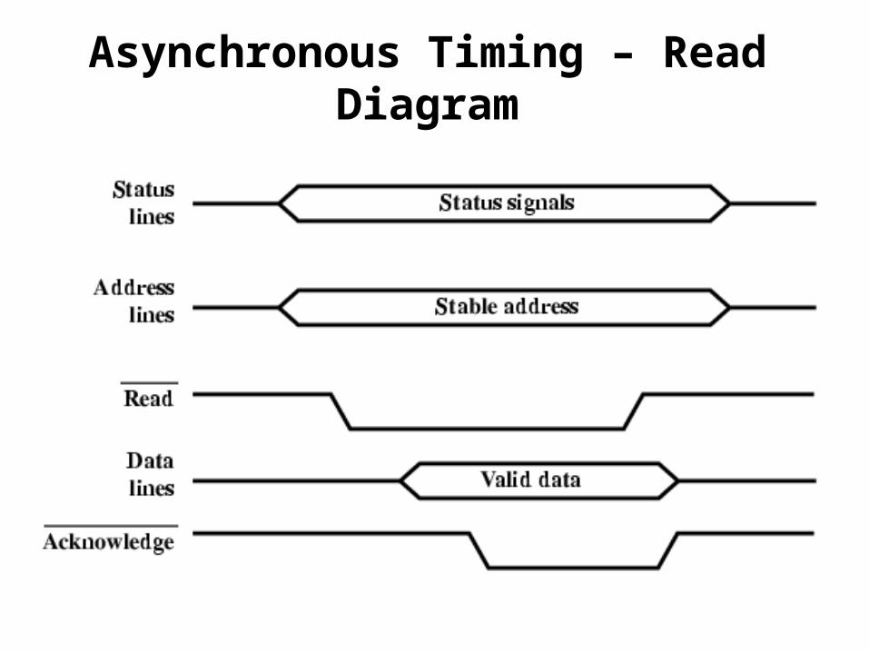
Asynchronous Timing – Read Diagram
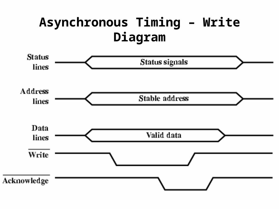
Asynchronous Timing – Write Diagram
Example - PCI Bus
• Peripheral Component Interconnection
• Intel released to public domain
• 32 or 64 bit
• 50 lines

Typical PCI Bus Usage
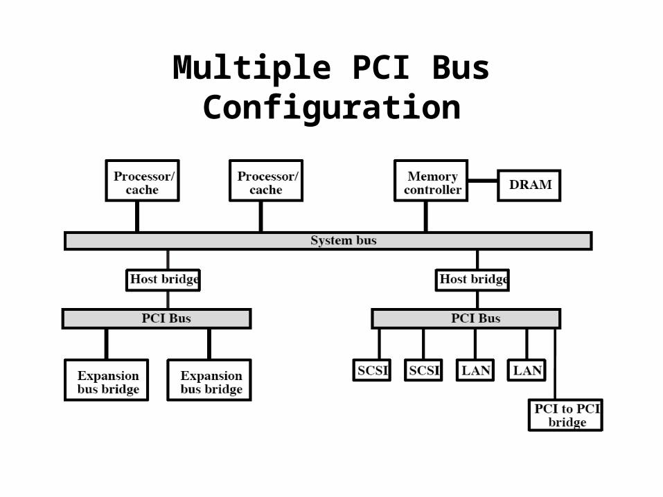
Multiple PCI Bus Configuration


PCI Commands
• Transaction between initiator (master) and target
• Master claims bus
• Determine type of transaction– e.g. I/O read/write
• Address phase
• One or more data phases

PCI Read Timing Diagram
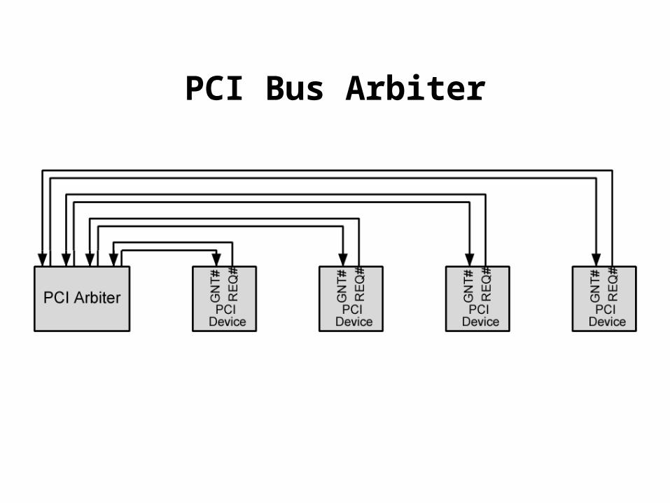
PCI Bus Arbiter

PCI Bus Arbitration Timing