csm nx-pnc ds e 1 1
TRANSCRIPT

1
CSM_NX-PNC_DS_E_1_1
NX-series PROFINET® Coupler Unit
NX-PNCConnecting to open industrial network standard PROFINET RT.• The PROFINET Coupler Unit is the link between the
PROFINET multivendor network and the NX-series I/O Units. With wide variety of the I/O Units, the NX-series is the perfect match for the multivendor Controllers.
Features• Up to 63 NX-IO Units can be connected to one PROFINET Coupler Unit. Standard and high-performance units can be mixed. *1• Each Coupler plus its I/O form just a single PROFINET IO device unit on the network.• PROFINET IO device configuration by Sysmac Studio can be done on-the-spot using the Coupler's built-in USB port.
*1. Input per Coupler Unit: Maximum 512 bytes, Output per Coupler Unit: Maximum 512 bytes

NX-PNC
2
System ConfigurationAn example of a system configuration for a PROFINET IO Device Terminal is shown below.
*1. For whether an NX Unit can be connected to the PROFINET Coupler Unit, refer to the version information in the user’s manual for the NX Unit.
Letter Item Description
(A) PROFINET IO Controller The PROFINET IO Controller manages the PROFINET network, monitors the status of the IO Devices, and exchanges IO data with the IO Devices.
(B) PROFINET Coupler Unit
The PROFINET Coupler Unit is an interface that performs IO refresh communications between a group of NX Units and the PROFINET Unit over a PROFINET network.The IO data for the NX Units is first accumulated in the PROFINET Coupler Unit and then all of the data is exchanged with the PROFINET Unit at the same time.You can connect up to 63 NX Units.
(C) NX Units *1 The NX Units perform IO processing with connected external devices. The NX IO Units perform IO refresh communications with the PROFINET IO Controller through the PROFINET Coupler Unit.
(D) End Cover The End Cover is attached to the end of the IO Device Terminal.
(E) Third party PROFINET IO Controller Software
The Third party PROFINET IO Controller Software runs on a personal computer and it is used to configure the PROFINET IO Controller and the connected PROFINET IO network with all IO Devices.
(F) GSDML file The GSDML file of the PROFINET Coupler Unit allows the user to configure the IO Controller Unit and the network for I/O data exchange with the PROFINET Coupler Unit and the NX IO System.
(G) Sysmac Studio Use Sysmac Studio to adjust the settings of the IO Device Terminal with the configuration and operation settings of the NX Units and PROFINET Coupler Unit.
(H) PROFINET IO Device The PROFINET IO Units that are coupled to the PROFINET IO Controller by means of the PROFINET Coupler Unit.
(A) PROFINET IO Controller
Communications cableEthernet cables
(B) NX-series PROFINET Coupler Unit NX-PNC202
(F) GSDML files
(D) End Cover(C) NX Units
PROFINET IO port
Peripheral USB port
Connection to peripheral USB port on PROFINET Coupler Unit
Ethernet switch
(H) PROFINET IO Device(G) Sysmac Studio
(E) Third party PROFINET IOController software
NX-PNC
3
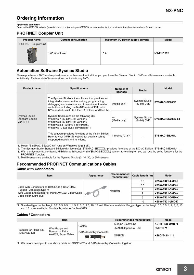
Ordering InformationApplicable standardsRefer to the OMRON website (www.ia.omron.com) or ask your OMRON representative for the most recent applicable standards for each model.
PROFINET Coupler Unit
Automation Software Sysmac StudioPlease purchase a DVD and required number of licenses the first time you purchase the Sysmac Studio. DVDs and licenses are available individually. Each model of licenses does not include any DVD.
*1. Model "SYSMAC-SE200D-64" runs on Windows 10 (64 bit).*2. The Sysmac Studio Standard Edition with license(s) (SYSMAC-SE@@@L) provides functions of the NX-I/O Edition (SYSMAC-NE001L). *3. With the Sysmac Studio Standard Edition with license(s) (SYSMAC-SE@@@L) version 1.45 or higher, you can use the setup functions for the
PROFINET Coupler.*4. Multi licenses are available for the Sysmac Studio (3, 10, 30, or 50 licenses).
Recommended PROFINET Communications CablesCable with Connectors
*1. Standard type cables length 0.2, 0.3, 0.5, 1, 1.5, 2, 3, 5, 7.5, 10, 15 and 20 m are available. Rugged type cables length 0.3, 0.5, 1, 2, 3, 5, 10 and 15 m are available. For details, refer to Cat.No.G019.
Cables / Connectors
*1. We recommend you to use above cable for PROFINET and RJ45 Assembly Connector together.
Product name Current consumption Maximum I/O power supply current ModelPROFINET Coupler Unit
1.60 W or lower 10 A NX-PNC202
Product name Specifications ModelNumber oflicenses Media
Sysmac StudioStandard EditionVer.1.@@
The Sysmac Studio is the software that provides an integrated environment for setting, programming, debugging and maintenance of machine automation controllers including the NJ/NX-series CPU Units, NYseries Industrial PC, EtherCAT Slave, and the HMI.
Sysmac Studio runs on the following OS.Windows 7 (32-bit/64-bit version)/Windows 8 (32-bit/64-bit version)/Windows 8.1 (32-bit/64-bit version)/Windows 10 (32-bit/64-bit version) *1
This software provides functions of the Vision Edition. Refer to your OMRON website for details such as supported models and functions.
--- (Media only)
Sysmac Studio (32-bit) DVD SYSMAC-SE200D
--- (Media only)
Sysmac Studio (64-bit) DVD SYSMAC-SE200D-64
1 license *2*3*4 --- SYSMAC-SE201L
Item Appearance Recommended manufacturer Cable length (m) Model
Cable with Connectors on Both Ends (RJ45/RJ45)Rugged RJ45 plugs type *1Wire Gauge and Number of Pairs: AWG22, 2-pair CableCable color: Light blue
OMRON
0.3 XS5W-T421-AMD-K0.5 XS5W-T421-BMD-K1 XS5W-T421-CMD-K2 XS5W-T421-DMD-K 5 XS5W-T421-GMD-K
10 XS5W-T421-JMD-K
Item Recommended manufacturer Model
Products for PROFINET(100BASE-TX)
Wire Gauge and Number of Pairs: AWG22, 2-pair Cable
CablesKuramo Electric Co. KETH-PSB-OMR *1JMACS Japan Co., Ltd. PNET/B *1
RJ45 Assembly ConnectorOMRON XS6G-T421-1 *1

NX-PNC
4
Optional Products
AccessoriesEnd Cover (NX-END01)One End Cover is provided together with the PROFINET Coupler Unit.
Product name Specification Model
Unit/Terminal Block Coding Pins Pins for 10 Units(30 terminal block pins and 30 Unit pins) NX-AUX02
Product nameSpecification
ModelNo. of terminals Terminal number
indicationsGround terminal
markTerminal current
capacityTerminal Block 8 A/B Provided 10 A NX-TBC082
Protrusions for removing the Unit
Unit hookup guide
Unit hookup guide
Protrusions for removing the Unit

NX-PNC
5
General Specifications
*1. Refer to the NX-series Digital IO Units User’s Manual (Cat. No. W521) for the vibration and shock resistance specifications of the Relay Output Unit.
*2. Refer to the OMRON website (http://www.ia.omron.com/) or consult your OMRON representative for the most recent applicable standards for each model.
Item SpecificationEnclosure Mounted in a panel
Grounding method Ground to 100 Ω or less
Operating environment
Ambient operating temperature 0 to 55°CAmbient operating humidity 10% to 95% (with no condensation or icing)
Atmosphere Must be free from corrosive gases.
Ambient storage temperature −25 to 70°C (with no condensation or icing)Altitude 2,000 m max.
Pollution degree 2 or less: Conforms to JIS B3502 and IEC 61131-2.
Noise immunity 2 kV on power supply line (Conforms to IEC61000-4-4.)
Overvoltage category Category II: Conforms to JIS B3502 and IEC 61131-2.
EMC immunity level Zone B
Vibration resistanceConforms to IEC 60068-2-6.5 to 8.4 Hz with 3.5-mm amplitude, 8.4 to 150 Hz, acceleration of 9.8 m/s2, 100 min each in X, Y, and Z directions (10 sweeps of 10 min each = 100 min total) *1
Shock resistance Conforms to IEC 60068-2-27. 147 m/s2, 3 times each in X, Y, and Z directions *1
Applicable standards *2 cULus: Listed UL508 and ANSI/ISA 12.12.01EC: EN 61131-2, C-Tick or RCM, KC

NX-PNC
6
PROFINET Specifications
*1. NX Unit data size is fixed 512Bytes. If this is not enough the shortage data is filled with padding data. The data in the padding part will be zero.
Item SpecificationName NX-PNC202
Manufacture ID 0x0264
Device ID 0x1500
PROFINET version 2.41
Application Relationship Max 1
Send Data Interval 64, 128, 256, 512 ms
Data Size (In)Status Max 28 Bytes
NX Unit In 512 Bytes *1
Data Size (Out)Unit Control 2 Bytes
NX Unit Out 512 Bytes *1
PROFINET interface
Protocol PROFINET IO
PROFINET unit type PROFINET IO Device
Isochronous mode No
Alarms No
Conformance Class Class-A
Link speed 100 Mbps
Physical layer 100BASE-TX
Topology Line, Tree, Star

NX-PNC
7
PROFINET Coupler Unit Specifications
Item Specification
Model NX-PNC202
Number of connectable NX Units 63 Units max
Refreshing method Free-run Refreshing
NX bus I/O data size Input: up to 512 bytesOutput: up to 512 bytes
Ethernet connection RJ45(2 port) with switching hub (Layer 2), 100 Mbps, full-duplex, auto-negotiate *1Max length of Ethernet cable: 100 m
*1.
*1. It is not supported to change duplex mode (full/half) and link speed (100/10 Mbps) manually.
Unit power supply
Power supply voltage 24 VDC (20.4 to 28.8 VDC)
NX Unit power supply capacity 10 W max.Refer to Installation orientation and restrictions for details.
NX Unit power supply efficiency 70%
Isolation method No isolation between NX Unit power supply and Unit power supply terminals
Current capacity of power supply terminals 4 A max.
I/O power supply
Power supply voltage 5 to 24 VDC (4.5 to 28.8 VDC)
Maximum I/O power supply current 10 ARefer to Installation orientation and restrictions for details.
Current capacity of power supply terminals 10 A max.
NX Unit power consumption 1.60 W max.
Current consumption from I/O power supply 10 mA max. (for 24 VDC)
Dielectric strength 510 VAC for 1 min, leakage current: 5 mA max. (between isolated circuits)
Insulation resistance 100 VDC, 20 MΩ min. (between isolated circuits)
USB port USB 2.0-compliant, Type-B, Max. 5m
Dimensions (width height depth) 46 mm * 100 mm * 71 mm
Weight 150 g max

NX-PNC
8
Item Specification
Installation orientation and restrictions
Installation orientation: 6 possible orientations Restrictions:• Used in the upright installation orientation.
• Used in any other orientation than the upright installation orientation.
0 10 20 30 40 45 50 55 60Ambient temperature [°C]
10
8
4
2
0
6
12
Unit power supply [W]10 W output, 40°C
8.5 W output, 55°C
0 10 20 30 40 45 50 55 60Ambient temperature [°C]
10
8
4
2
0
6
12
Unit power supply [W]10 W output, 40 °C
6.0 W output, 55°C
0 10 20 30 40 45 50 55 60Ambient temperature [°C]
10
8
4
2
0
6
12
°C
6 A current, 55°C
10 A current, 45I/O power supply [A]

NX-PNC
9
Circuit layout
Terminal arrangement
Accessory End Cover (NX-END01): 1
Item Specification
NX Unit power supply +
NX Unit power supply −Terminal
block I/O power supply +I/O power supply −
DIN Track contact plate
Peripheral USB port
IN communications connector
OUT communications connector
NX bus connector
UV UV UG UG IOV
IOG
UNIT PWR LED
I/O PWR LED
Internal circuits
Non-isolated power supply circuits
IOV
UG
UV
IOG
UV
UG
A1
A8
B1
B8
Unit power supply (24 VDC)
Through-wiring for unwired terminals.
I/O power supply (5 to 24 VDC)
Ground to 100 Ω or less.

NX-PNC
10
Configuration UnitRefer to the user's manuals for information on the NX Units that can be connected to the NX-series PROFINET Coupler Unit.
PROFINET Coupler Unit
I/O Units
Temperature Control Units
Load Cell Input Unit
Position Interface Units
System Units
RFID Units
Unit Model
PROFINET Coupler Unit NX-PNC202
UnitModel
2-point Units 4-point Units 8-point Units 16-point Units 32-point Units
Digital Input Unit −
NX-ID3317NX-ID3343NX-ID3417NX-ID3443NX-IA3117
NX-ID4342NX-ID4442
NX-ID5142-1NX-ID5142-5NX-ID5342NX-ID5442
NX-ID6142-5NX-ID6142-6
Digital Output Unit NX-OC2633NX-OC2733
NX-OD3121NX-OD3153NX-OD3256NX-OD3257NX-OD3268
NX-OD4121NX-OD4256NX-OC4633
NX-OD5121NX-OD5121-1NX-OD5121-5NX-OD5256NX-OD5256-1NX-OD5256-5
NX-OD6121-5NX-OD6121-6NX-OD6256-5
Digital Mixed I/O Unit − − −NX-MD6121-5NX-MD6121-6NX-MD6256-5
−
Analog Input Unit
NX-AD2603NX-AD2604NX-AD2608NX-AD2203NX-AD2204NX-AD2208
NX-AD3603NX-AD3604NX-AD3608NX-AD3203NX-AD3204NX-AD3208
NX-AD4603NX-AD4604NX-AD4608NX-AD4203NX-AD4204NX-AD4208
− −
Analog Output Unit
NX-DA2603NX-DA2605NX-DA2203NX-DA2205
NX-DA3603NX-DA3605NX-DA3203NX-DA3205
− − −
Temperature Input Unit
NX-TS2101NX-TS2102NX-TS2104NX-TS2201NX-TS2202NX-TS2204
NX-TS3101NX-TS3102NX-TS3104NX-TS3201NX-TS3202NX-TS3204
− − −
Heater Burnout Detection Unit − NX-HB3101NX-HB3201 − − −
UnitModel
2CH 4CH
Temperature Control Unit NX-TC2405, NX-TC2406, NX-TC2407, NX-TC2408 NX-TC3405, NX-TC3406, NX-TC3407, NX-TC3408
Unit Model
Load Cell Input Unit NX-RS1201, NX-RS1201-K
UnitModel
1CH 2CH 4CH
Incremental Encoder Input Unit NX-EC0112, NX-EC0122, NX-EC0132, NX-EC0142 NX-EC0212, NX-EC0222 −
SSI Input Unit NX-ECS112 NX-ECS212 −
Unit ModelAdditional NX Unit Power Supply Unit NX-PD1000
Additional I/O Power Supply Unit NX-PF0630, NX-PF0730
I/O Power Supply Connection Unit NX-PC0010, NX-PC0020, NX-PC0030
Shield Connection Unit NX-TBX01
Unit ModelRFID Unit NX-V680C1, NX-V680C2

NX-PNC
11
External InterfacePROFINET Coupler Unit NX-PNC202
Terminal Block
Letter Name Function
(A) Marker attachment locations The locations where markers are attached. The markers made by OMRON are installed for the factory setting. Commercially available markers can also be installed.
(B) Unit specifications The specifications of the Unit are engraved in the side of the casing.
(C) NX bus connector This connector is used to connect the PROFINET Coupler Unit to the NX Unit on the right of the Coupler Unit.
(D) DIN Track mounting hooks These hooks are used to mount the PROFINET Coupler Unit to a DIN Track.
(E) Protrusions for removing the Unit The protrusions to hold when removing the Unit.
(F) Unit hookup guides These guides are used to connect two Units.
(G) Indicators The indicators show the current operating status of the Unit and the status of the power supply.
(H) Peripheral USB port This port is used to connect to the Sysmac Studio.
(I) Terminal block The terminal block is used to connect to the power supply cables and ground wire.
(J) DIN Track contact plate This plate is connected internally to the functional ground terminal on the terminal block.
(K) DIP switch Not used
(L) Communications connectors These connectors are connected to the communications cables of the PROFINET network.
(M) Rotary switches Not used
Letter Name Function
(A) Terminal number indicationsThe terminal numbers (A1 to A8 and B1 to B8) are displayed.The terminal number indicators are the same regardless of the number of terminals on the terminal block.
(B) Release holes Insert a flat-blade screwdriver into these holes to connect and remove the wires.
(C) Terminal holes The wires are inserted into these holes.
(D) Ground terminal mark This mark indicates the ground terminals.
(G)(H)
(I)
(F)
(L)
(M)
(L)(K)
(D)
(F)
(E)
(E)
(B)(C)
(A)
01234
56789ABCDEF
NX-PNC202
Port2
01234
56789ABCDEF
P1P2
RUN/ERR TS
COMM/BF
(J)
RSV
Port1
8-terminal type
(A)
A1
A2
A3
A4
A5
A6
A7
A8
B1
B2
B3
B4
B5
B6
B7
B8
(B)
(C)
(D)

NX-PNC
12
Dimensions (Unit: mm)
PROFINET Coupler Unit Only
With Cables Connected
*1. This dimension depends on the specifications of the commercially available USB certified cable. Check the specifications of the USB cable that is used.
*2. This is the dimension from the back of the Unit to the communications cables.· 100 mm: When an MPS588-C Connector is used.· 120 mm: When an XS6G-T421-1 Connector is used.
8071
65.2
104.5100
48.146
1.5
1.5 0.55
0123
456789ABCDEF01
23456789ABCDEF
NX-PNC202
COMM/BF
RUN/ERR
Port1
Port2
100 to 120 *2
USB cable
Communications cable
*1
715.8

NX-PNC
13
End Cover
*1. This is the shape for Units with lot numbers through December 2014.
71
121.5
100
1.5
A A*1

NX-PNC
14
Related ManualsThe following manuals are related. Use these manuals for reference.
Manual name Cat. No. Model numbers Application Description
NX-series PROFINET Coupler Unit User’s Manual W623 NX-PNC
Learning how to use an NX-series PROFINET Coupler Unit
The following items are described: the overall system and configuration methods of a PROFINET Coupler Unit, and information on hardware, setup, and functions to set up, control, and monitor NX Units.
Sysmac Studio Version 1 Operation Manual W504 SYSMAC-SE2
Learning about the operating procedures and functions of the Sysmac Studio.
Describes the operating procedures of the Sysmac Studio.
NX-series Data Reference Manual W525 NX-
Referencing lists of the data that is required to configure systems with NX-series Units
Lists of the power consumptions, weights, and other NX Unit data that is required to configure systems with NX-series Units are provided.
NX-series Digital IO Units User’s Manual W521
NX-IDNX-IANX-OCNX-OD
Learning how to use NX-series Digital IO Units
The hardware, setup methods, and functions of the NX-series Digital IO Units are described.
NX-series Analog IO Units User's Manual for Analog Input Units and Analog Output Units
W522 NX-ADNX-DA
Learning how to use NX-series Analog Input Units and Analog Output Units
The hardware, setup methods, and functions of the NX-series Analog Input Units and Analog Output Units are described.
NX-series System Units User’s Manual W523
NX-PD1NX-PF0NX-PC0NX-TBX01
Learning how to use NX-series System Units
The hardware and functions of the NX-series System Units are described.
NX-series Position Interface Units User’s Manual W524
NX-EC0NX-ECSNX-PG0
Learning how to use NX-series Position Interface Units
The hardware, setup methods, and functions of the NX-series Incremental Encoder Input Units, SSI Input Units, and Pulse Output Unit are described.
NX-series Load Cell Input Unit User's Manual W565 NX-RS
Learning how to use NX-series Load Cell Input Unit
The hardware, setup methods, and functions of the NX-series Load Cell Input Unit are described.
NX-series Analog IO Units User’s Manual for Temperature Input Units and Heater Burnout Detection Units
W566 NX-TSNX-HB
Learning how to use NX-series Temperature Input Units and Heater Burnout Detection Units
The hardware, setup methods, and functions of the NX-series Temperature Input Units and Heater Burnout Detection Units are described.
NX-series Temperature Control Units User's Manual H228 NX-TC
Learning how to use NX-series Temperature Control Units.
The hardware, setup methods, and functions of the NX-series Temperature Control Units are described.
• Sysmac and SYSMAC are trademarks or registered trademarks of OMRON Corporation in Japan and other countries for OMRON factory automation products.
• Microsoft and Windows are either registered trademarks or trademarks of Microsoft Corporation in the United States and other countries.• EtherCAT® is registered trademark and patented technology, licensed by Beckhoff Automation GmbH, Germany.• EtherNet/IP is trademarks of ODVA.• Other company names and product names in this document are the trademarks or registered trademarks of their respective companies.