csi-based wifi-inertial state...
TRANSCRIPT

CSI-Based WiFi-Inertial State Estimation
Bing Li, Shengkai Zhang and Shaojie Shen
Abstract— WiFi-based localization has received increasingattentions these years because WiFi devices are low-cost anduniversal. Recent years, tens of WiFi-based localization sys-tems have been proposed which could achieve decimeter-levelaccuracy with the commercial NIC and with no specializedinfrastructure. However, such systems require the positions ofthe Access Points or fingerprint map to be known in advance.In this paper, we present CWISE, an accurate WiFi-InertialSLAM system without requirement for Access Points’ positions,specialized infrastructure or fingerprinting. CWISE relies onlyon a commercial NIC with two antennas and an IMU. We testthe CWISE system on a flying quadrotor and it shows that thesystem could work in real time and obtain mean accuracy of1.60m.
I. INTRODUCTION
State estimation is the fundamental requirement for manyrobotic applications such as UAV, self-driving car. A largenumber of researchers have proposed various state estimationmethods using laser scanner [1] [2], stereo cameras[3] [4],monocular camera[5] [6] [7], and RGB-D sensors[8]. Laser-based methods could achieve centimeter level accuracy atindoor environments, but they are limited by the requirementfor expensive laser sensor. Vision-based approaches obtaingreat success due to the property of low cost, high accuracyand light weight, however, they require sufficient lightingand features, they do not work at dark or featureless environ-ments. While WiFi-based approaches could potentially solvethese problem, because WiFi devices are cheap, universaland unaffected by the light or feature.
The main goal of this paper is to develop a WiFi-basedlocalization system that is:• deployable: The system should be easily deployed on
existing commodity WiFi infrastructure without requir-ing any hardware change to the access points(APs)
• accurate: The system should be as accurate as compara-ble with GPS to be used for autonomous flight of aerialrobots.
• on-the-fly: The system should be always ready to flywithout any preparing work when changes to a differentplace, for example, no need to measure the positions ofthe APS and no need to build the fingerprint map of theWiFi signal.
To the best of our knowledge, there is no WiFi-based sys-tem satisfying all these three properties. RSSI based systemsare easily deployable but are not accurate, their accuracyranges from 2-4 m [9] which is not sufficient for robotic
All authors are with the Department of Electronic andComputer Engineering, Hong Kong University of Science andTechnology, Hong Kong, China. [email protected],[email protected], [email protected]
navigation. Recent methods that based on angle of arrival(AoA) estimation such as ArrayTrack [10] and Phaser [11]are accurate but they need to modify the hardware to get amultiple antennas (5-8) system. Other AoA-based approachessuch as Ubicarse [12] and SpotFi [13] are deployable andaccurate, but they cannot be used on highly dynamic system.Additionally, all these approaches above need to know thepositions of APs in advance, they are not on-the-fly.
The main contribution of this paper is a real time WiFi-Inertial state estimation system which is deployable, accurateand on-the-fly. Our system estimates the location of boththe platform and APs using a SLAM-style formulation. Weimplement our system on DJI Matrices 100 platform, and theonboard processor is Intel NUC computer running UbuntuLinux. The computer is equipped with a commercial Intel5300 WiFi card and a LORD MicroStrain IMU (3DM-GX4-25). Our system could achieve the mean accuracy of 1.60m compared with the position fused from GPS and IMU,it requires no hardware modification to the APs and noknowledge of APs’ positions or fingerprint map. Only theangle of arrival extracted from CSI and IMU information areused (sect. III), and sliding window filter is used to make themetric scale observable which is similar to monocular visual-inertial fusion[14] (sect. IV).
The rest of this paper is organized as follows: Section IIgives an overview of the related work. Section III presents thecalculation of AoA with commercial NIC card. Section IVtalks about the fusion of WiFi and IMU. Section V showsthe simulation and experimental results and concludes thepaper with some future work.
II. RELATED WORK
WiFi-based localization is well studied problem and alarge number of methods have been proposed in recent years,which mainly could be classified into three types.
RSSI based approaches: The idea of such system is mea-suring the received signal strength from multiple APs whichis related to the distances between the target and the APs, andsolving the target’s position by combining all the constraintstogether as a nonlinear least square problem. Since the modelof RSSI depends not only on the distance but also on theenvironment, for example, the RSSI through the wall decadesgreatly, most RSSI based approaches only achieve room-level accuracy. The best known such system could achieve amedian accuracy of 2-4 m[15] [16]. Additionally, the APs’positions must be known to solve the nonlinear least squareproblem.
Fingerprinting based approaches: This class of systemsfirst need to collect fingerprint such as the vector of RSSIs

AP1
AP2AP3
AP4
Platform with multiple antennas
Fig. 1: System Setup
or CSIs to all APs for all the cells on the map, then couldlocate the target by choosing the most similar vector in themap[17] [18]. The best known system using this approachachieves the median accuracy of 0.6 m [17]. However,these systems require expensive and recurring fingerprintingoperation when the environment is changed(e.g., the door isopened or the chair is moved).
AoA based approaches: After CSI-tools using Intel 5300[19] and Atheros ar9300 [20] wireless card being released,AoA estimation has become available with commercial WiFicard and AoA based WiFi localization has become a popularresearch area for indoor localization. Several researchershave successfully implemented their accurate AoA basedWiFi localization system using CSI information from com-mercial WiFi card [12] [11] [13] [21], e.g., Ubicarse [12],SpotFi [13], and Phaser [11]. Phaser could achieve medianaccuracy of 1 m, however, it needs to modify the hardware tocombine two wireless cards with three antenna as one withfive antennas. Ubicarse could achieve the median accuracy of0.4 m without hardware modification in complex indoor en-vironments, however, it needs the user to rotate two antennaswhile walking. SpotFi also could achieve comparable resultas Ubicarse while it does not need to rotate the antennas anddoes not need additional inertial sorcerers. Unfortunately, allof these approaches above assume that the APs’ positionsare known in advance to locate the target.
III. CSI-BASED AOA ESTIMATIONA. CSI Measurement
It is well-known that the performance of wireless networksdepends heavily on the physical layer details of the RFchannel[19]. However, until 2009, only high-level informa-tion about wireless conditions like RSSI values was availablefrom commodity 802.11 wireless card which contributes littleto understanding the channel state. Fortunately, the IEEE802.11n standard defines a mechanism for transmission ofCSI between the receiver and the transmitter. Unlike theRSSI, the CSI records the signal strength and the phaseinformation for all sub-carriers between each pair of trans-mitter and receiver. This standardized mechanism allows the
transmitter to improve the link performance via transmitbeam-forming. D. Halperin et al.[19] and Yaxiong [20]have built their tools for collecting CSI information at sub-carrier level on Intel 5300 and Atheros ar9300 wireless cardrespectively. A large number of researchers have successfullyimplemented WiFi localization system based on these toolsand some of which could achieve decimeter level medianaccuracy.
Channel state information(CSI) is information that repre-sents the channel’s properties of a communication link withamplitude and phase, it reveals the combined effect for thewireless channel, for example, fading and scattering. To bemore specifically, CSI describes how a signal propagatesfrom the transmitter(s) to the receiver(s)[22]. In fact, the ac-curacy of CSI greatly influences communication performanceof OFDM(Orthogonal Frequency Division Multiplexing) sys-tem.
Because electromagnetic signals superimpose on the wire-less channel, we can express the propagation as a linearsystem:
y = Hx + n (1)
where x is the transmitted signal, y is the received signal,H is the channel matrix and n is the noise signal.
B. AoA Estimation
To estimate the AoA of the signal from the APs, at leasttwo antennas are required to measure the relative phasebetween two antennas. For simplicity, it is assumed that boththe transmitter and the receivers lie on a two-dimensionalplane and the signal has only single path. Suppose the AoAof the line-of-sight signal is α and the angle of the antennaarray on the plane is φ, as illustrated in figure 2, the wirelesschannels measured by the receive antenna 1 and receiveantenna 2 at ith sub-carrier can be written as the complexnumber:
y1,i = ‖y1,i‖e−j2πdλi xi (2)
y2,i = ‖y2,i‖e−j2π(d−rcos(α−φ))
λi xi (3)
where r denotes distance between two antennas, drepresents the traveling distance from the transmitter tothe first antenna, and λi is the signal wavelength of ith
sub-carrier. According to the IEEE 802.11n-2009 standard,the 20MHz bandwidth for each channel is divided into 64equally spaced sub-carriers with 125KHz bandwidth. Forthe Intel 5300 WiFi card, only 30 sub-carriers of index si ={−28,−26,−24,−22,−20,−18,−16,−14,−12,−10,−8,−6,−4,−2,−1, 1, 3, 5, 7, 9, 11, 13, 15, 17, 19, 21, 23, 25, 27,28} are measured, and the corresponding frequencies are
fi = f + si ∗ 125KHz
where f is the central frequency of the channel.We use λ represents the smallest wavelength for all the
sub-carriers and we choose r = λ2 to maximize the resolution

...
Wireless Signal
Antenn
a Arra
y
1
2
M
rФ
xy
α
d
Fig. 2: Illustration of Antenna Array
of phase measurement while avoiding the phase ambiguity.Note the assumption that d >> r, i.e., the transmitter is faraway from the receiver relative to the distance between thetwo antennas.
To get the equation unrelated to distance between thetransmitter and receiver, we define the relative wirelesschannel at the ith sub-carrier as, yi = y2,iy
∗1,i, where (.)∗
means the complex conjugate. Mathematically, the relativechannel is simplified as,
yi = y2,iy∗1,i = ‖y1,i‖‖y2,i‖‖xi‖2e
j2πrcos(α−φ)λ (4)
The phase measurement equation could be written as,
6 yi = ψi =2πrcos(α− φ)
λi(5)
where ψi is the measured phase of ith sub-carrier.Therefore, the estimated angle is
α = ± arccos(ψiλi2πr
) + φ (6)
We use the mean value of estimated AoA from all sub-carriers as the final estimation.
According to (6), there are two possible AoAs because ofside ambiguity. The side ambiguity could be solved usingthe method used in Ubiscare [12] by rotating the antennas.We only use this method at initialization step, after that theAoA will be tracked.
IV. LINEAR SLIDING WINDOW WIFI-INERTIALFUSION
In this section, we present an optimized-based WiFi-Inertial fusion method, which is modified from the originalvisual-inertial fusion framework [23] for accurate state esti-mation. Note that WiFi only provides AoA information, butwith IMU we are able to estimate the metric position andvelocity.
We consider N as the earth’s inertial frame, W as the WiFiantenna frame, B as the IMU body frame, Bk as the bodyframe while taking kth WiFi measurement. Since the IMUruns at a higher rate in our system, there are more thanone IMU measurements between Bk and Bk+1. We assumethat the WiFi antenna and the IMU are pre-calibrated suchthat the transformation between body frame and the WiFi
Subcarrier Index
0 5 10 15 20 25 30
Unw
raped C
SI phase
-30
-25
-20
-15
-10
-5
0
5
antenna 1 packet 1
antenna 1 packet 2
antenna 1 packet 3
antenna 2 packet 1
antenna 2 packet 2
antenna 2 packet 3
(a)
Subcarrier Index
0 5 10 15 20 25 30R
ela
tive C
SI phase
-3
-2
-1
0
1
2
3packet 1
packet 2
packet 3
(b)
Fig. 3: CSI phase: (a) unwrapped CSI phase, (b) relativephase between antenna 1 and antenna 2. It can be seen thatthe phases between different sub-carriers varies greatly, butthe relative phases between two antennas are very stable
antenna frame is known. pXY , vXY and RXY are 3D position,
velocity and rotation of frame X with respect to frame Y.gG = [0, 0, g]T is the gravity vector in the earth’s inertialframe, and gX is the earth’s gravity vector expressed in frameX.
A. Inertial Preintegration
Given more than one IMU measurements between Bk andBk+1, we could summarize all these IMU measurementsas one motion constrain according to Inertial PreintegrationTheory [24].
The normal propagation model for position and velocityin the inertial frame can be written as,
pGBk+1= pGBk + vGBk∆t+
∫ ∫ Bk+1
Bk
(RGBaB − gG)dt2 (7)
vGBk+1= vGBk +
∫ Bk+1
Bk
(RGBaB − gG)dt (8)
where ∆t is the time difference between Bk and Bk+1 andaB is the accelerometer measurement in the body frame. Itis obvious that the rotation between the inertial frame andbody frame, RGB needs to be known in order to propagatethe state with the IMU measurements. According to the
formulation in (7) and (8), if the first pose of the systemis used as the reference frame, all the IMU measurementsbetween frame Bk and Bk+1 can be summarized as onlyone motion constraint, (7) and (8) can be rewritten as,
pB0
Bk+1= pB0
Bk+ vB0
Bk∆t− gB0∆t2/2 + RB0
BkαBkBk+1
(9)
vB0
Bk+1= vB0
Bk− gB0∆t+ RB0
BkβBkBk+1
(10)
where
αBkBk+1=
∫ ∫ Bk+1
Bk
RBkB aB∆t2 (11)
βBkBk+1=
∫ Bk+1
Bk
RBkB aB∆t (12)
RB0
Bkis the rotation between B0 and Bk, which can be
obtained by fusing measurements from gyroscope, mag-netometer and accelerometer with Extended Kalman Filter[25]. αBkBk+1
and βBkBk+1can be obtained with only the
IMU measurements from Bk to Bk+1. We can see that theconstraint equations (9) and (10) for the state (pB0
Bk, vB0
Bk,
gB0 ) are all linear now.
B. Linear Sliding Window Estimator
We apply a sliding window graph-based formulation be-cause it can accurately solve the problem in constant com-putation complexity. The full state parameter vector is
x = [xB0
B0,xB0
B1, ...xB0
BN,a1,a2, ...aM ]
xB0
Bk= [pB0
Bk,vBkBk ,g
Bk ] for k = 1, 2...N
pB0
B0= [0, 0, 0]
where xB0
Bkis the kth WiFi state, N is the number of WiFi
state in the sliding window, M is the number of the AccessPoints have been observed within the sliding window. al isthe lth Access Point’s position. We keep the body framevelocity vBkBk and gravity vector gBk in the state vector toreduce the impact of rotation error on the estimation results.
Since the rotation is fixed, we can formulate the problemas a linear WiFi Inertial Navigation System by combiningall measurements from both IMU and WiFi and solve themaximum likelihood estimate by minimizing the sum of theMahalanobis norm of all measurement errors:
minχ
{(bp − Λpχ) +
∑k∈D
‖zBkBk+1− HBk
Bk+1χ‖
2
PBkBk+1
+∑
(l,j)∈C
‖zBjl − HBjl χ‖
2
PBjl
} (13)
where the measurements {zBkBk+1, HBk
Bk+1,PBk
Bk+1} and
{zBjl , HBjl ,P
Bjl } are defined in sect. IV-C and sect. IV-
D respectively. D is the set of all IMU measurements andC is the set of WiFi measurements between all the AccessPoints and WiFi states within the sliding window. {bp,Λp}
is the optional prior information for the system. Since allthe constraints are linear, this system can be solved by re-organizing in the following form:
(Λp + Λimu + ΛWiFi)χ = (bp + bimu + bWiFi) (14)
where {Λimu,bimu} and {ΛWiFi,bWiFi} are informationmatrices and vectors for IMU and WiFi measurements re-spectively.
It should be noted that since all the constraints are linear,the system in (14) has unique solution without the priorinformation:
(Λimu + ΛWiFi)χ = (bimu + bWiFi) (15)
To bound the computational complexity, only the lateststates are kept in the state vector by removing the oldestrobot state and out-of-range APs. However, if the parametersare removed from the system equations directly, some infor-mation will be lost and the scale will become unobservableusing only the measurements within the sliding window. Thecorrect way to remove the parameters is to marginalize themout, which is equivalent to Schur complement to the leastsquare equations as described in [14] and [23].
C. IMU Measurement Model
Assume the rotation RB0
Bkis given, we can rewrite (9) and
(10) as a linear function of the state χ: αBkBk+1
βBkBk+1
0
=
RBkB0(pBk+1
B0− pBkB0
)− vBkBk∆t+ gBk∆t2/2
RBk+1
B0vBk+1
Bk+1− vBkBk + gBk∆t
RBk+1
BkgBk+1 − gBk
=HBk
Bk+1χ (16)
The last block line in (16) is the constraint about thegravity vector. We estimate the gravity vector for eachpose in order to avoid the negative effects due to possibleaccumulated rotation error. All variables except the positioncomponent are independent of the accumulated rotation RBkB0
,making them insensitive to rotation error. The linear IMUmeasurement model has the form:
zBkBk+1∼ N (HBk
Bk+1χ,
PBαβkBk+1
0
0 PBgk
Bk+1
) (17)
Note that αBkBk+1and βBkBk+1
are correlated since they bothcome from IMU measurements between Bk and Bk+1. Thejoint covariance matrix P
BαβkBk+1
can be calculated using thepre-integration technique proposed in [26].
D. WiFi Measurement Model
Let the lth AP be the first detected in the ith frame, thedirection of this AP observed in the kth WiFi frame, dkl canbe expressed as,
RBwdkl ∼ RBkB0(ai − pB0
Bk) (18)

Where RBw is the rotation from WiFi frame to Body frame.Specially, for two-dimensional case, if the estimated AoA isα, the direction dkl can be expressed as,
dkl = [cos(α), sin(α), 0]T
Using cross product, the constraint can be converted tolinear form:
bRB0
BkRBwdklc×(ai − pB0
Bk) = 0 (19)
The equation (19) can be rewritten as
0 = bRB0
BkRBwdklc×(ai − pB0
Bk) = HBk
l χ (20)
and WiFi measurement model has the form:
zBkl ∼ N (HBkl χ, dBkl
2PBkl ) (21)
where dBkl is the distance from the lth Access Point to theBk frame and PBk
l is the WiFi observation noise. Note thatdBkl is unknown initially, we initialize it with an identicalvalue to all the measurements.
V. RESULTS
A. Simulation Result
As there is no public data with the ground truth for WiFilocalization, we generate simulation data in gazebo and ROS.Four APs are placed on the ground and the platform flies asa circle pattern. The noise level of the related sensors are asfollow:
TABLE I: Noise level of the simulated sensors
Sensor Type Noise type Noise levelgyroscope Gaussian 0.01
accelerometer Gaussian 0.01angle of arrival sensor Gaussian 0.1
20
X
-2-4-6
-4
-2
0
Y
2
4
0
1
2
Z
ground truth
estimated position
Fig. 4: Simulation result (trajectory plot)
The simulation results in figure 5 and 6 prove that thetrajectory of the MAV and APs’ position could be estimatedsimultaneously using only the IMU and the AoA measure-ments.
Time (sec)
0 10 20 30 40 50 60 70
X(m
)
-5
0
5
Time (sec)
0 10 20 30 40 50 60 70
Y (
m)
-10
-5
0
5
Time (sec)
0 10 20 30 40 50 60 70
Z (
m)
0
1
2
3
Fig. 5: Simulation result (platform position). It can be seenthat the estimated platform’s position will converge to theground truth with enough motion.
Time (sec)
0 10 20 30 40 50 60
X (
m)
0
5
10
15
Time (sec)
0 10 20 30 40 50 60Y
(m
)0
5
10
Time (sec)
0 10 20 30 40 50 60
Z (
m)
-3
-2
-1
0
Fig. 6: Simulation result (AP position). It shows that theAP’s position will converge to the ground truth with enoughmotion.
B. Implementation Details
We implement CWISE on an Intel NUC equipped withIntel 5300 WiFi card and a LORD MicroStrain IMU (3DM-GX4-25). We build on the 802.11n CSI tool [19] to collectthe CSI information for any successfully received packetswith a specialized destination MAC address. The accesspoints work on injection mode and the receiver workson monitor mode, and all the Intel 5300 WiFi cards areconfigured on 5GHz channel since the phase reading on2.4GHz always have a shift of kπ
2 . Through at most threeantennas are supported for Intel 5300 WiFi card, we onlyuse two of them because the phase reading of the thirdantenna is really noisy for injection/monitor mode. Specially,the wavelength λ = 0.0564m (5.32Ghz) and the distancebetween two antennas r = λ
2 = 0.0282m.The APs are controlled by a server to broadcast the random
packets one by one, there is a short interval about 2 msbetween the broadcasting of different APs.
C. Experimental Results
We use an Intel NUC with Core i5 4250 processor (1.3GHz) to compute onboard. We conduct multiple experiments
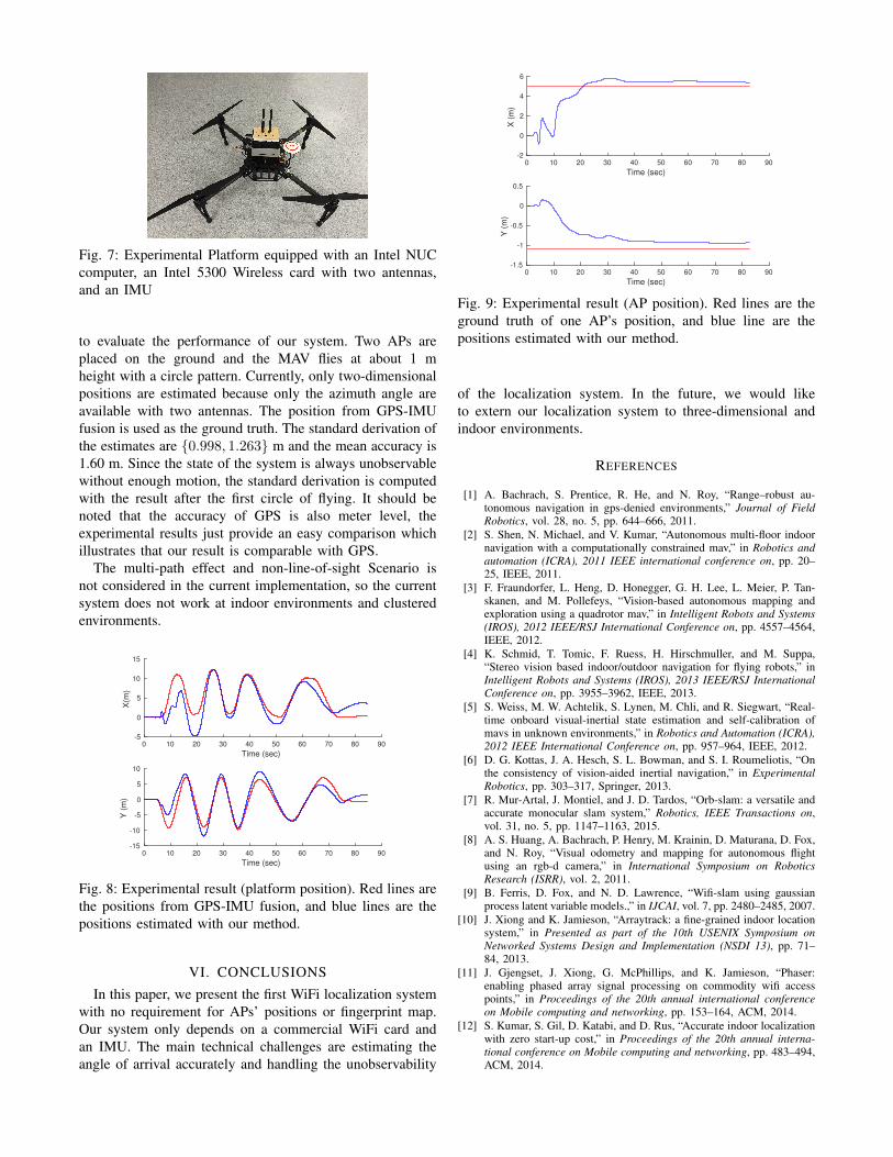
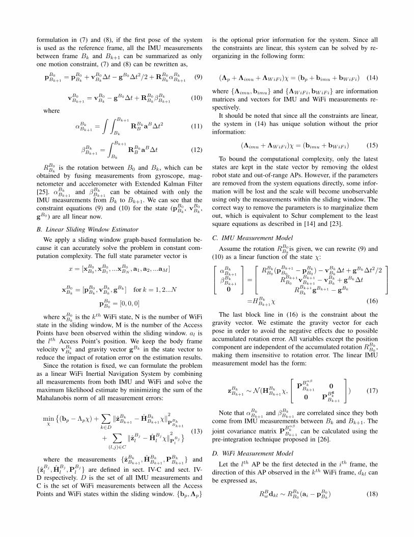
Fig. 7: Experimental Platform equipped with an Intel NUCcomputer, an Intel 5300 Wireless card with two antennas,and an IMU
to evaluate the performance of our system. Two APs areplaced on the ground and the MAV flies at about 1 mheight with a circle pattern. Currently, only two-dimensionalpositions are estimated because only the azimuth angle areavailable with two antennas. The position from GPS-IMUfusion is used as the ground truth. The standard derivation ofthe estimates are {0.998, 1.263} m and the mean accuracy is1.60 m. Since the state of the system is always unobservablewithout enough motion, the standard derivation is computedwith the result after the first circle of flying. It should benoted that the accuracy of GPS is also meter level, theexperimental results just provide an easy comparison whichillustrates that our result is comparable with GPS.
The multi-path effect and non-line-of-sight Scenario isnot considered in the current implementation, so the currentsystem does not work at indoor environments and clusteredenvironments.
Time (sec)
0 10 20 30 40 50 60 70 80 90
X(m
)
-5
0
5
10
15
Time (sec)
0 10 20 30 40 50 60 70 80 90
Y (
m)
-15
-10
-5
0
5
10
Fig. 8: Experimental result (platform position). Red lines arethe positions from GPS-IMU fusion, and blue lines are thepositions estimated with our method.
VI. CONCLUSIONS
In this paper, we present the first WiFi localization systemwith no requirement for APs’ positions or fingerprint map.Our system only depends on a commercial WiFi card andan IMU. The main technical challenges are estimating theangle of arrival accurately and handling the unobservability
Time (sec)
0 10 20 30 40 50 60 70 80 90
X (
m)
-2
0
2
4
6
Time (sec)
0 10 20 30 40 50 60 70 80 90
Y (
m)
-1.5
-1
-0.5
0
0.5
Fig. 9: Experimental result (AP position). Red lines are theground truth of one AP’s position, and blue line are thepositions estimated with our method.
of the localization system. In the future, we would liketo extern our localization system to three-dimensional andindoor environments.
REFERENCES
[1] A. Bachrach, S. Prentice, R. He, and N. Roy, “Range–robust au-tonomous navigation in gps-denied environments,” Journal of FieldRobotics, vol. 28, no. 5, pp. 644–666, 2011.
[2] S. Shen, N. Michael, and V. Kumar, “Autonomous multi-floor indoornavigation with a computationally constrained mav,” in Robotics andautomation (ICRA), 2011 IEEE international conference on, pp. 20–25, IEEE, 2011.
[3] F. Fraundorfer, L. Heng, D. Honegger, G. H. Lee, L. Meier, P. Tan-skanen, and M. Pollefeys, “Vision-based autonomous mapping andexploration using a quadrotor mav,” in Intelligent Robots and Systems(IROS), 2012 IEEE/RSJ International Conference on, pp. 4557–4564,IEEE, 2012.
[4] K. Schmid, T. Tomic, F. Ruess, H. Hirschmuller, and M. Suppa,“Stereo vision based indoor/outdoor navigation for flying robots,” inIntelligent Robots and Systems (IROS), 2013 IEEE/RSJ InternationalConference on, pp. 3955–3962, IEEE, 2013.
[5] S. Weiss, M. W. Achtelik, S. Lynen, M. Chli, and R. Siegwart, “Real-time onboard visual-inertial state estimation and self-calibration ofmavs in unknown environments,” in Robotics and Automation (ICRA),2012 IEEE International Conference on, pp. 957–964, IEEE, 2012.
[6] D. G. Kottas, J. A. Hesch, S. L. Bowman, and S. I. Roumeliotis, “Onthe consistency of vision-aided inertial navigation,” in ExperimentalRobotics, pp. 303–317, Springer, 2013.
[7] R. Mur-Artal, J. Montiel, and J. D. Tardos, “Orb-slam: a versatile andaccurate monocular slam system,” Robotics, IEEE Transactions on,vol. 31, no. 5, pp. 1147–1163, 2015.
[8] A. S. Huang, A. Bachrach, P. Henry, M. Krainin, D. Maturana, D. Fox,and N. Roy, “Visual odometry and mapping for autonomous flightusing an rgb-d camera,” in International Symposium on RoboticsResearch (ISRR), vol. 2, 2011.
[9] B. Ferris, D. Fox, and N. D. Lawrence, “Wifi-slam using gaussianprocess latent variable models.,” in IJCAI, vol. 7, pp. 2480–2485, 2007.
[10] J. Xiong and K. Jamieson, “Arraytrack: a fine-grained indoor locationsystem,” in Presented as part of the 10th USENIX Symposium onNetworked Systems Design and Implementation (NSDI 13), pp. 71–84, 2013.
[11] J. Gjengset, J. Xiong, G. McPhillips, and K. Jamieson, “Phaser:enabling phased array signal processing on commodity wifi accesspoints,” in Proceedings of the 20th annual international conferenceon Mobile computing and networking, pp. 153–164, ACM, 2014.
[12] S. Kumar, S. Gil, D. Katabi, and D. Rus, “Accurate indoor localizationwith zero start-up cost,” in Proceedings of the 20th annual interna-tional conference on Mobile computing and networking, pp. 483–494,ACM, 2014.
[13] M. Kotaru, K. Joshi, D. Bharadia, and S. Katti, “Spotfi: Decimeterlevel localization using wifi,” in Proceedings of the 2015 ACM Confer-ence on Special Interest Group on Data Communication, pp. 269–282,ACM, 2015.
[14] G. Sibley, L. Matthies, and G. Sukhatme, “Sliding window filter withapplication to planetary landing,” Journal of Field Robotics, vol. 27,no. 5, pp. 587–608, 2010.
[15] P. Bahl and V. N. Padmanabhan, “Radar: An in-building rf-baseduser location and tracking system,” in INFOCOM 2000. NineteenthAnnual Joint Conference of the IEEE Computer and CommunicationsSocieties. Proceedings. IEEE, vol. 2, pp. 775–784, Ieee, 2000.
[16] K. Chintalapudi, A. Padmanabha Iyer, and V. N. Padmanabhan,“Indoor localization without the pain,” in Proceedings of the sixteenthannual international conference on Mobile computing and networking,pp. 173–184, ACM, 2010.
[17] M. Youssef and A. Agrawala, “The horus wlan location determinationsystem,” in Proceedings of the 3rd international conference on Mobilesystems, applications, and services, pp. 205–218, ACM, 2005.
[18] X. Wang, L. Gao, S. Mao, and S. Pandey, “Deepfi: Deep learningfor indoor fingerprinting using channel state information,” in WirelessCommunications and Networking Conference (WCNC), 2015 IEEE,pp. 1666–1671, IEEE, 2015.
[19] D. Halperin, W. Hu, A. Sheth, and D. Wetherall, “Tool release:gathering 802.11 n traces with channel state information,” ACMSIGCOMM Computer Communication Review, vol. 41, no. 1, pp. 53–53, 2011.
[20] Z. Li, Y. Xie, M. Li, and K. Jamieson, “Recitation: Rehearsing wirelesspacket reception in software,” in Proceedings of the 21st Annual Inter-national Conference on Mobile Computing and Networking, pp. 291–303, ACM, 2015.
[21] S. Kumar, E. Hamed, D. Katabi, and L. Erran Li, “Lte radio analyticsmade easy and accessible,” in ACM SIGCOMM Computer Communi-cation Review, vol. 44, pp. 211–222, ACM, 2014.
[22] K. Wu, J. Xiao, Y. Yi, M. Gao, and L. M. Ni, “Fila: Fine-grained in-door localization,” in INFOCOM, 2012 Proceedings IEEE, pp. 2210–2218, IEEE, 2012.
[23] S. Shen, Y. Mulgaonkar, N. Michael, and V. Kumar, “Initialization-
free monocular visual-inertial state estimation with application toautonomous mavs,” in Experimental Robotics, pp. 211–227, Springer,2016.
[24] T. Lupton and S. Sukkarieh, “Visual-inertial-aided navigation for high-dynamic motion in built environments without initial conditions,”Robotics, IEEE Transactions on, vol. 28, no. 1, pp. 61–76, 2012.
[25] N. Trawny and S. I. Roumeliotis, “Indirect kalman filter for 3d attitudeestimation,” University of Minnesota, Dept. of Comp. Sci. & Eng.,Tech. Rep, vol. 2, p. 2005, 2005.
[26] C. Forster, L. Carlone, F. Dellaert, and D. Scaramuzza, “Imu preinte-gration on manifold for efficient visual-inertial maximum-a-posterioriestimation,” in Robotics: Science and Systems XI, no. EPFL-CONF-214687, 2015.