csci-1680 link layer wrap-up -...
TRANSCRIPT
CSCI-1680Link Layer Wrap-Up
BasedpartlyonlecturenotesbyDavidMazières,PhilLevis, John Jannotti
Rodrigo Fonseca

Administrivia
• Homework I out later today, due next Thursday
Today: Link Layer (cont.)
• Framing• Reliability– Error correction– Sliding window
• Medium Access Control• Case study: Ethernet • Link Layer Switching
Medium Access Control
• Control access to shared physical medium– E.g., who can talk when?– If everyone talks at once, no one hears anything– Job of the Link Layer
• Two conflicting goals– Maximize utilization when one node sending– Approach 1/N allocation when N nodes sending
Different Approaches
• Partitioned Access– Time Division Multiple Access (TDMA)– Frequency Division Multiple Access (FDMA)– Code Division Multiple Access (CDMA)
• Random Access– ALOHA/ Slotted ALOHA– Carrier Sense Multiple Access / Collision Detection
(CSMA/CD)– Carrier Sense Multiple Access / Collision Avoidance
(CSMA/CA)– RTS/CTS (Request to Send/Clear to Send)– Token-based
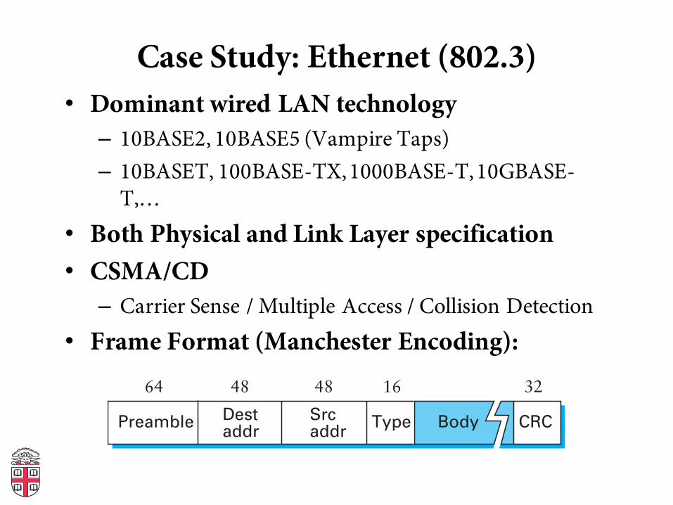
Case Study: Ethernet (802.3)• Dominant wired LAN technology– 10BASE2, 10BASE5 (Vampire Taps)– 10BASET, 100BASE-TX, 1000BASE-T, 10GBASE-
T,…• Both Physical and Link Layer specification• CSMA/CD– Carrier Sense / Multiple Access / Collision Detection
• Frame Format (Manchester Encoding):
Destaddr
64 48 32
CRCPreamble Srcaddr
Type Body
1648
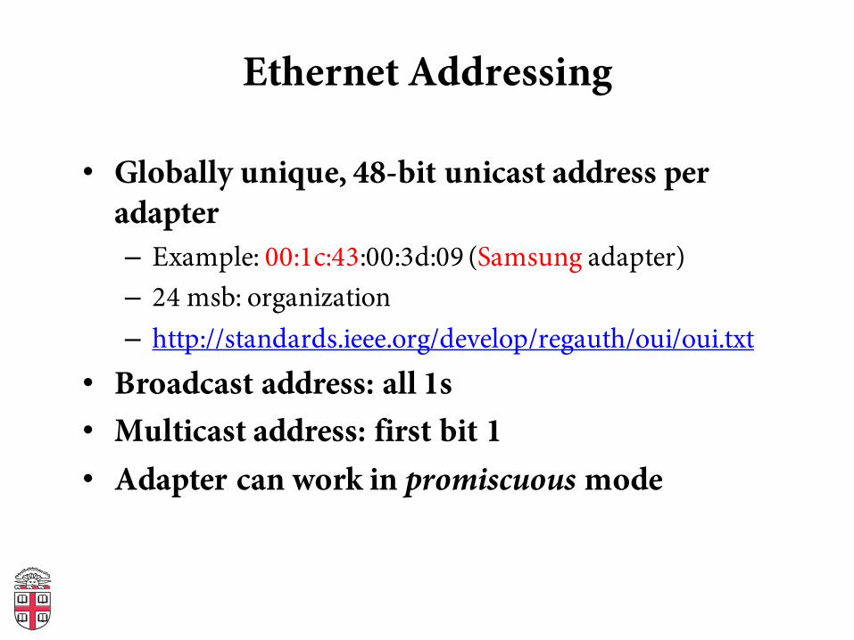
Ethernet Addressing
• Globally unique, 48-bit unicast address per adapter– Example: 00:1c:43:00:3d:09 (Samsung adapter)– 24 msb: organization– http://standards.ieee.org/develop/regauth/oui/oui.txt
• Broadcast address: all 1s• Multicast address: first bit 1• Adapter can work in promiscuous mode
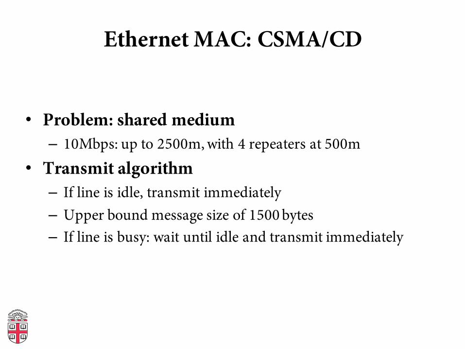
Ethernet MAC: CSMA/CD
• Problem: shared medium– 10Mbps: up to 2500m, with 4 repeaters at 500m
• Transmit algorithm– If line is idle, transmit immediately– Upper bound message size of 1500 bytes– If line is busy: wait until idle and transmit immediately
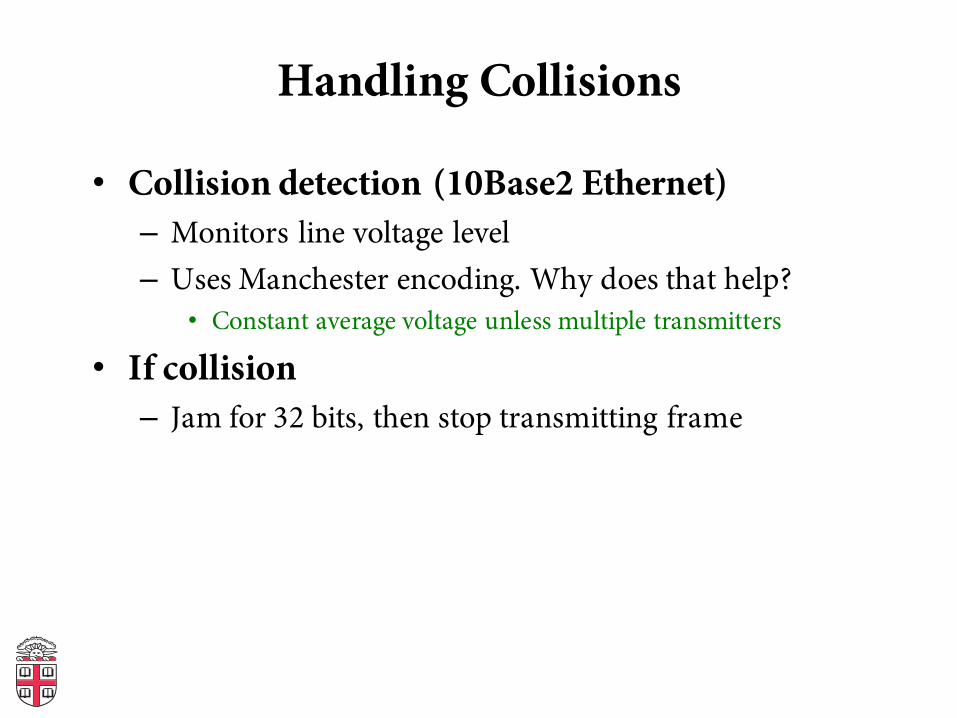
Handling Collisions
• Collision detection (10Base2 Ethernet)– Monitors line voltage level– Uses Manchester encoding. Why does that help?
• Constant average voltage unless multiple transmitters
• If collision– Jam for 32 bits, then stop transmitting frame
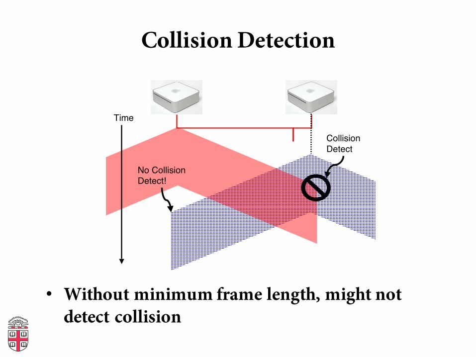
Collision Detection
• Without minimum frame length, might not detect collision
Violating Timing Constraints
Time
Collision
Detect
No Collision
Detect!
• Without min packet size, might miss collision
Handling Collisions
• Collision detection (10Base2 Ethernet)– Monitors line voltage level– Uses Manchester encoding. Why does that help?
• Constant average voltage unless multiple transmitters
• If collision– Jam for 32 bits, then stop transmitting frame
• Collision detection constrains protocol– Must ensure transmission time ≥ 2x propagation
delay– Imposes min. packet size (64 bytes or 512 bits)– Imposes maximum network diameter (2500m)
When to transmit again?
• Delay and try again: exponential backoff• nth time: k × 51.2μs, for k = U{0..(2min(n,10)-1)}– 1st time: 0 or 51.2μs– 2nd time: 0, 51.2, 102.4, or 153.6μs
• Give up after several times (usually 16)
Capture Effect
• Exponential backoff leads to self-adaptive use of channel
• A and B are trying to transmit, and collide• Both will back off either 0 or 51.2μs• Say A wins.• Next time, collide again. – A will wait between 0 or 1 slots– B will wait between 0, 1, 2, or 3 slots
• …
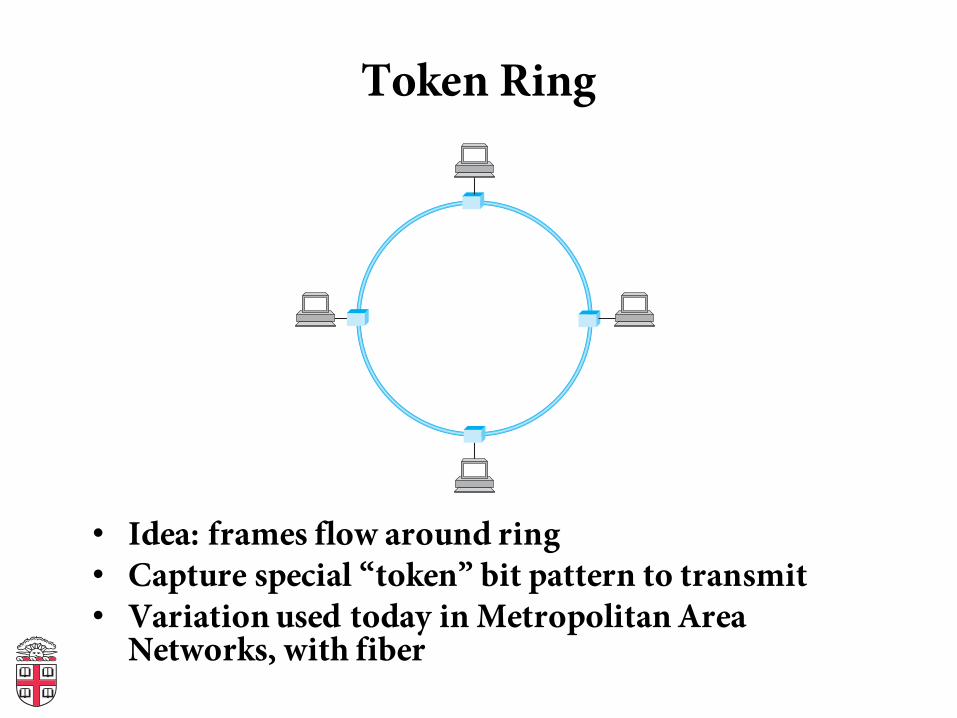
Token Ring
• Idea: frames flow around ring• Capture special “token” bit pattern to transmit• Variation used today in Metropolitan Area
Networks, with fiber
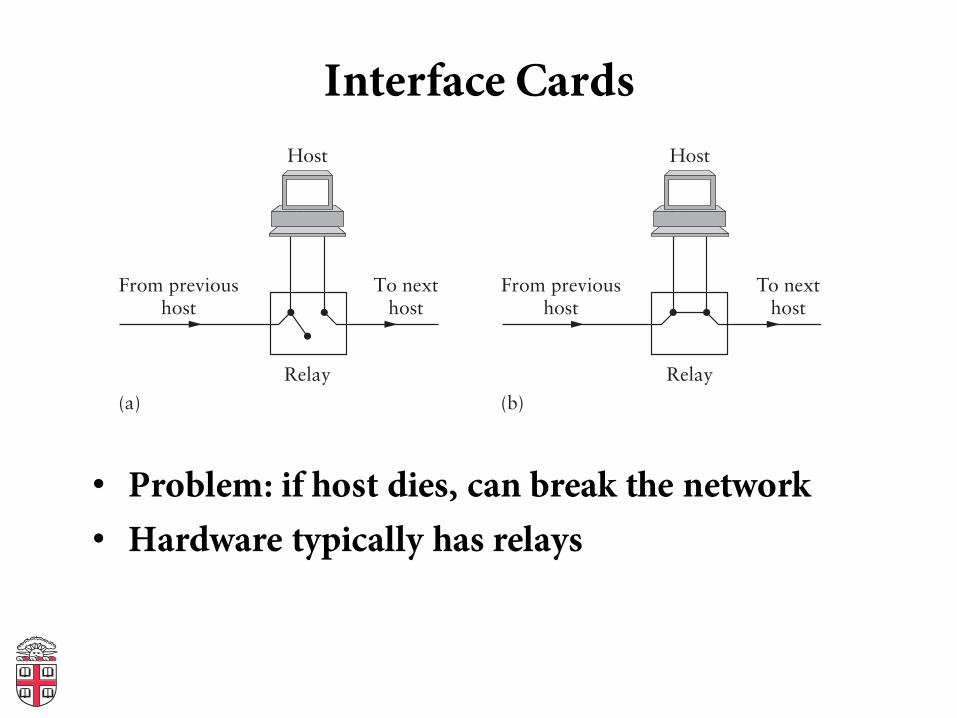
Interface Cards
• Problem: if host dies, can break the network• Hardware typically has relays
Host
From previoushost
To nexthost
Relay
(a)
Host
Host Host
From previoushost
To nexthost
Relay
(b)
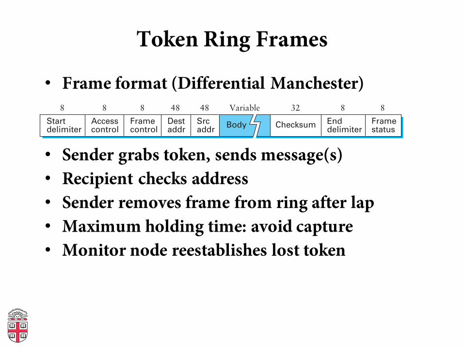
Token Ring Frames
• Frame format (Differential Manchester)
• Sender grabs token, sends message(s)• Recipient checks address• Sender removes frame from ring after lap• Maximum holding time: avoid capture• Monitor node reestablishes lost token
Body ChecksumSrcaddr
Variable48
Destaddr
48 32
Enddelimiter
8
Framestatus
8
Framecontrol
8
Accesscontrol
8
Startdelimiter
8
Bridging
Bridges and Extended LANs
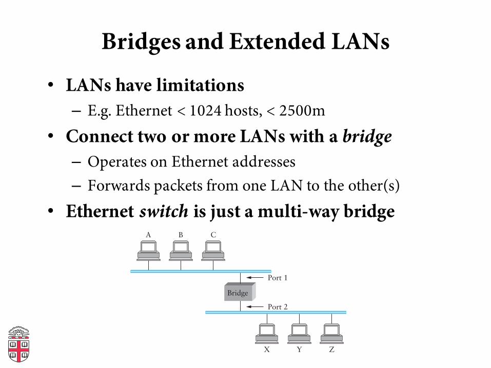
• LANs have limitations– E.g. Ethernet < 1024 hosts, < 2500m
• Connect two or more LANs with a bridge– Operates on Ethernet addresses– Forwards packets from one LAN to the other(s)
• Ethernet switch is just a multi-way bridgeA
Bridge
B C
X Y Z
Port 1
Port 2
Learning Bridges
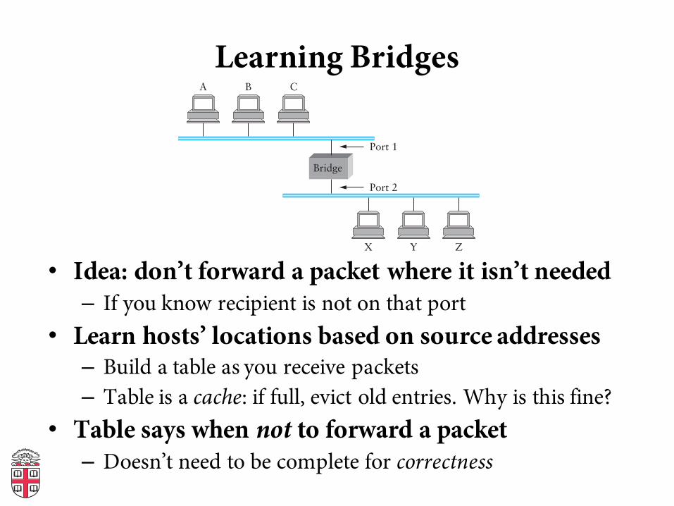
• Idea: don’t forward a packet where it isn’t needed– If you know recipient is not on that port
• Learn hosts’ locations based on source addresses– Build a table as you receive packets– Table is a cache: if full, evict old entries. Why is this fine?
• Table says when not to forward a packet– Doesn’t need to be complete for correctness
A
Bridge
B C
X Y Z
Port 1
Port 2
Attack on a Learning Switch
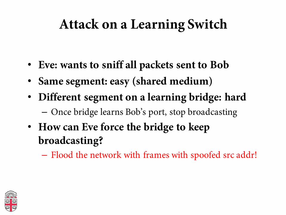
• Eve: wants to sniff all packets sent to Bob• Same segment: easy (shared medium)• Different segment on a learning bridge: hard– Once bridge learns Bob’s port, stop broadcasting
• How can Eve force the bridge to keep broadcasting?– Flood the network with frames with spoofed src addr!
Bridges
• Unicast: forward with filtering• Broadcast: always forward• Multicast: always forward or learn groups• Difference between bridges and repeaters?– Bridges: same broadcast domain; copy frames– Repeaters: same broadcast and collision domain; copy
signals
Switching
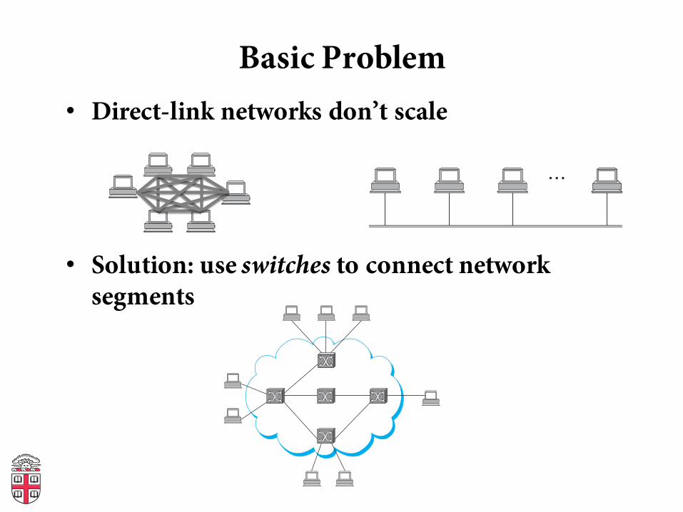
Basic Problem• Direct-link networks don’t scale
• Solution: use switches to connect network segments
(a)
(b)…
(a)
(b)…
(a)
(b)…
(a)
(b)…
(a)
(b)…
(a)
(b)…
(a)
(b)…
Switching
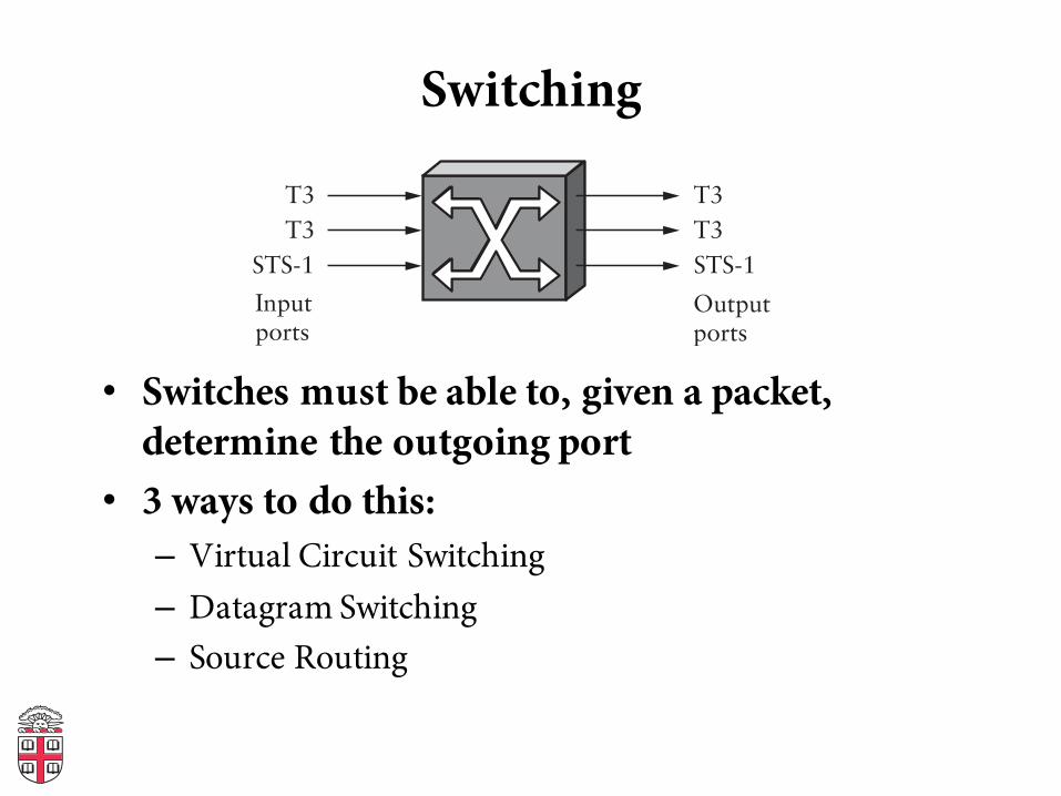
• Switches must be able to, given a packet, determine the outgoing port
• 3 ways to do this:– Virtual Circuit Switching– Datagram Switching– Source Routing
Inputports
T3
T3
STS-1
T3
T3
STS-1
Switch
Outputports
Virtual Circuit Switching
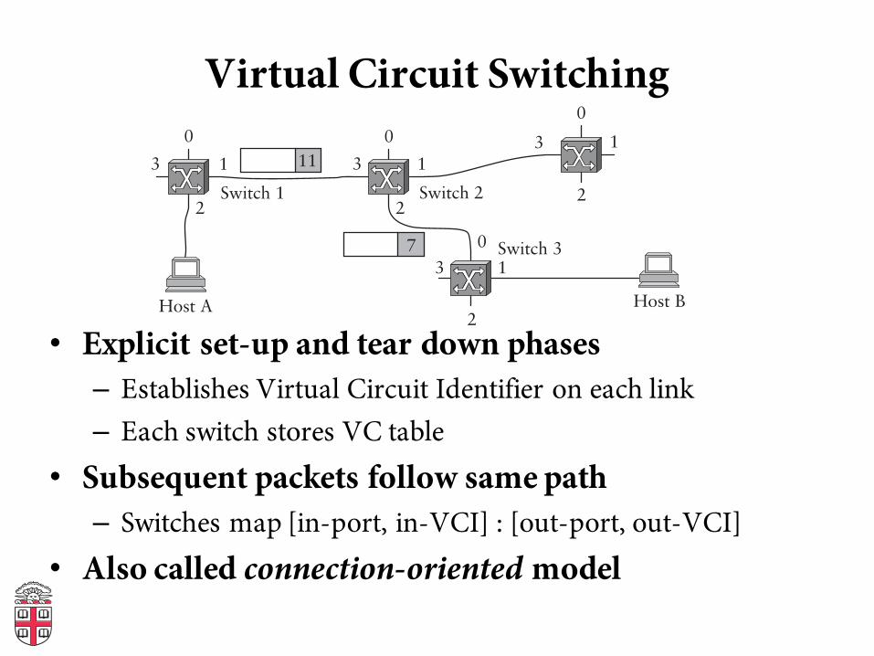
• Explicit set-up and tear down phases– Establishes Virtual Circuit Identifier on each link– Each switch stores VC table
• Subsequent packets follow same path– Switches map [in-port, in-VCI] : [out-port, out-VCI]
• Also called connection-oriented model
0
1
2
3
0
1
2
3
0
1
2
3
0
1
2
3
Host A Host B
Switch 3
Switch 2Switch 1
7
11
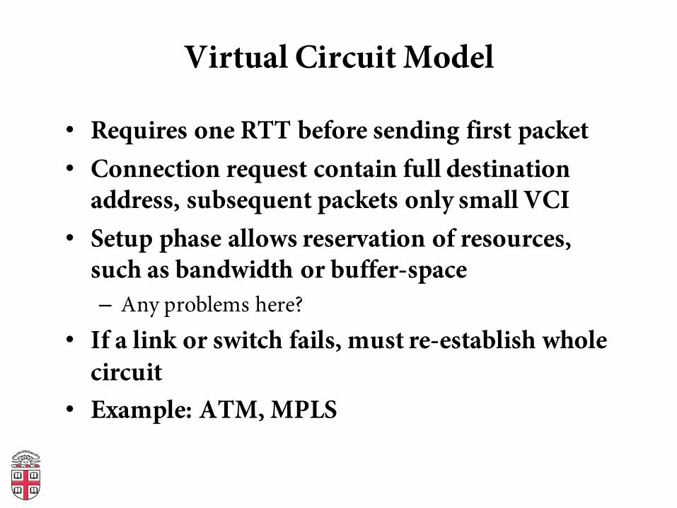
Virtual Circuit Model
• Requires one RTT before sending first packet• Connection request contain full destination
address, subsequent packets only small VCI• Setup phase allows reservation of resources,
such as bandwidth or buffer-space– Any problems here?
• If a link or switch fails, must re-establish whole circuit
• Example: ATM, MPLS
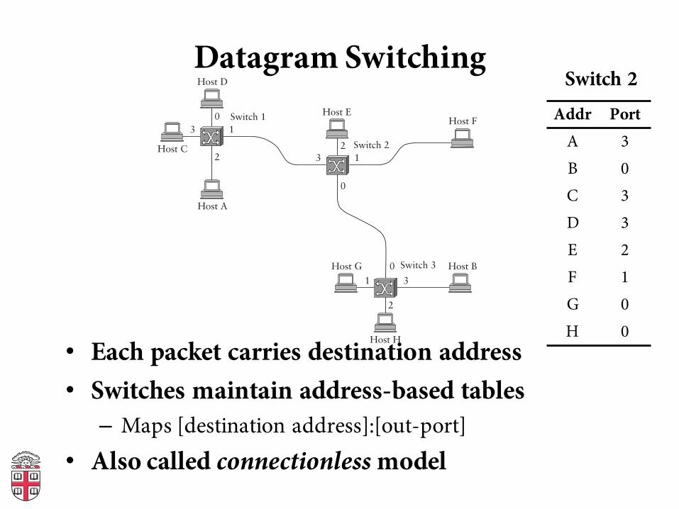
Datagram Switching
• Each packet carries destination address• Switches maintain address-based tables– Maps [destination address]:[out-port]
• Also called connectionless model
0
132
01 3
2
013
2
Switch 3 Host B
Switch 2
Host A
Switch 1
Host C
Host D
Host EHost F
Host G
Host H
Addr PortA 3B 0C 3D 3E 2F 1G 0H 0
Switch 2
Datagram Switching
• No delay for connection setup• Source can’t know if network can deliver a
packet• Possible to route around failures• Higher overhead per-packet• Potentially larger tables at switches
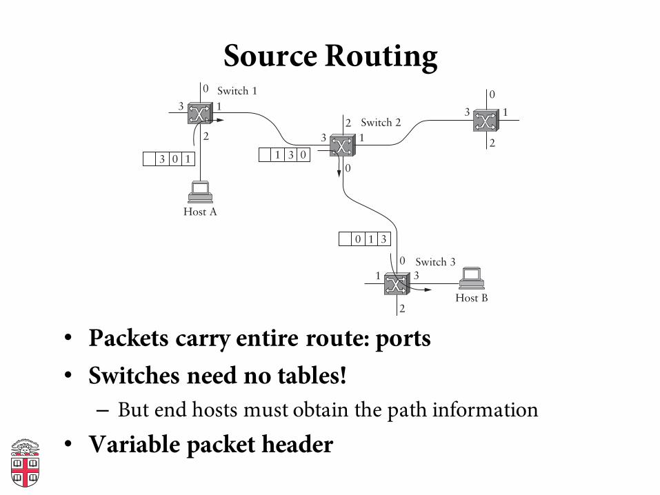
Source Routing
• Packets carry entire route: ports• Switches need no tables!– But end hosts must obtain the path information
• Variable packet header
0
132
01 3
2
0
13
2
0
13
23 0 1 3 01
30 1
Switch 3
Host B
Switch 2
Host A
Switch 1
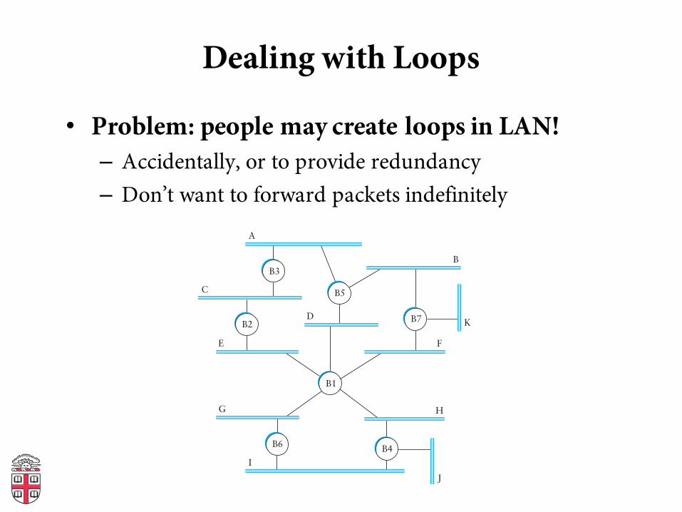
Dealing with Loops
• Problem: people may create loops in LAN!– Accidentally, or to provide redundancy– Don’t want to forward packets indefinitely
A
C
E
D
B
K
F
H
J
G
I
B3
B7
B4
B2
B5
B1
B6
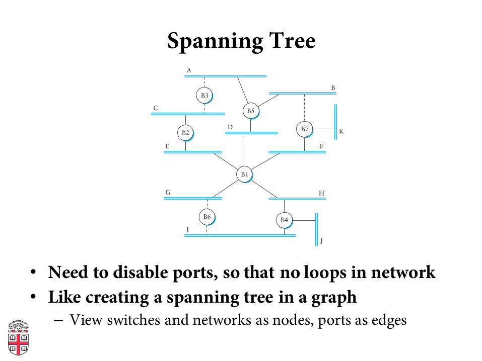
Spanning Tree
• Need to disable ports, so that no loops in network• Like creating a spanning tree in a graph– View switches and networks as nodes, ports as edges
A
C
E
D
B
K
F
H
J
G
I
B5
B2
B3
B7
B4
B1
B6
Distributed Spanning Tree Algorithm
• Every bridge has a unique ID (Ethernet address)• Goal:– Bridge with the smallest ID is the root– Each segment has one designated bridge, responsible for
forwarding its packets towards the root• Bridge closest to root is designated bridge• If there is a tie, bridge with lowest ID wins
Spanning Tree Protocol
• Send message when you think you are the root• Otherwise, forward messages from best known root– Add one to distance before forwarding– Don’t forward over discarding ports (see next slide)
• Spanning Tree messages contain:– ID of bridge sending the message– ID sender believes to be the root– Distance (in hops) from sender to root
• Bridges remember best config msg on each port• In the end, only root is generating messages
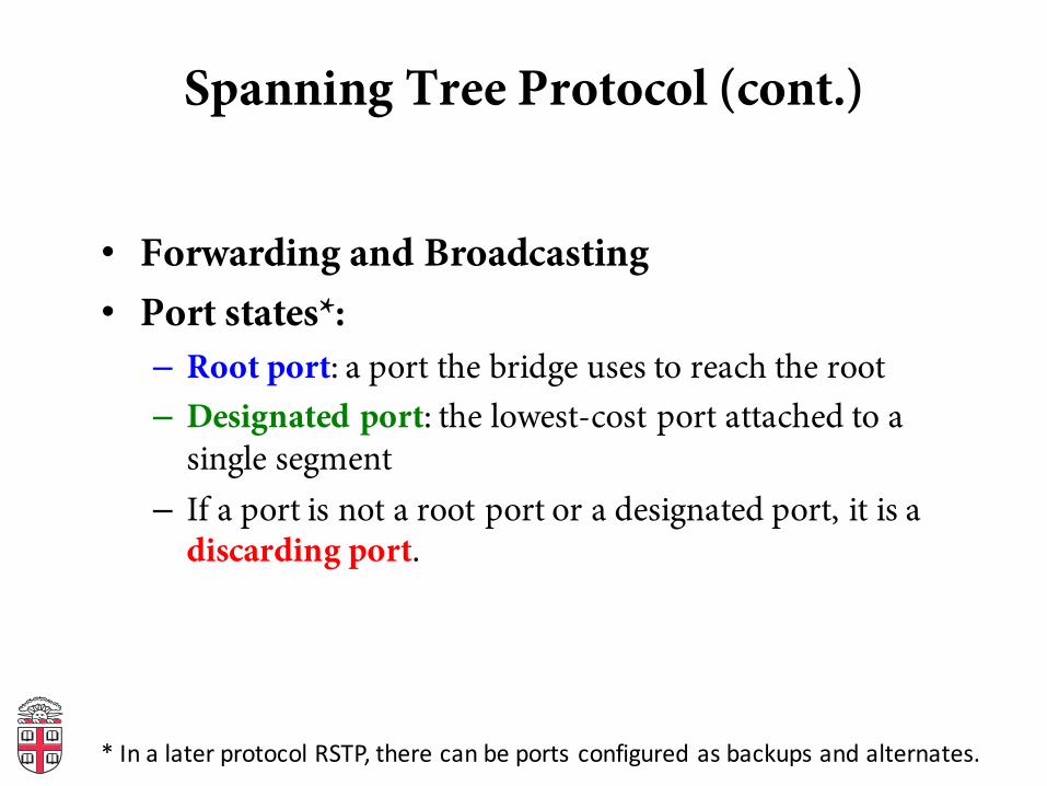
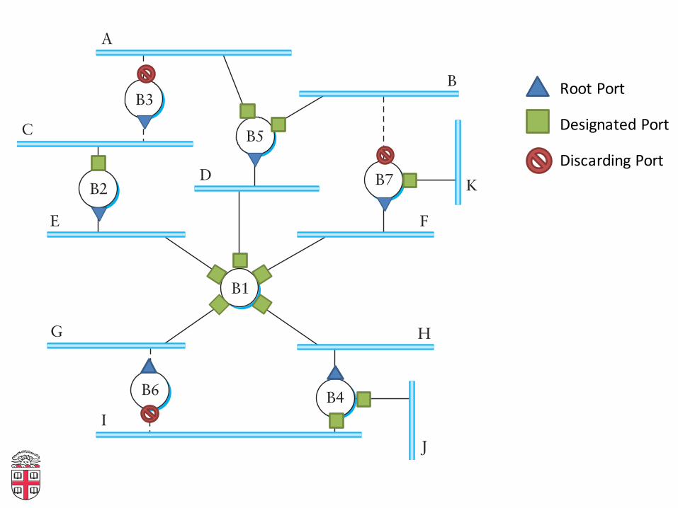
Spanning Tree Protocol (cont.)
• Forwarding and Broadcasting• Port states*:– Root port: a port the bridge uses to reach the root– Designated port: the lowest-cost port attached to a
single segment– If a port is not a root port or a designated port, it is a
discarding port.
*InalaterprotocolRSTP,therecanbeportsconfiguredasbackupsandalternates.
A
C
E
D
B
K
F
H
J
G
I
B5
B2
B3
B7
B4
B1
B6
RootPort
DesignatedPort
DiscardingPort
Algorhyme
I think that I shall never seea graph more lovely that a tree.A tree whose crucial propertyis loop-free connectivity.A tree that must be sure to spanso packet can reach every LAN.First the root must be selected.By ID, it is elected.Least cost paths from root are traced.In the tree, these paths are placed.A mesh is made by folks like me,then bridges find a spanning tree.
Radia Perlman
Limitations of Bridges
• Scaling– Spanning tree algorithm doesn’t scale– Broadcast does not scale– No way to route around congested links, even if path
exists• May violate assumptions– Could confuse some applications that assume single
segment• Much more likely to drop packets• Makes latency between nodes non-uniform
– Beware of transparency
VLANs
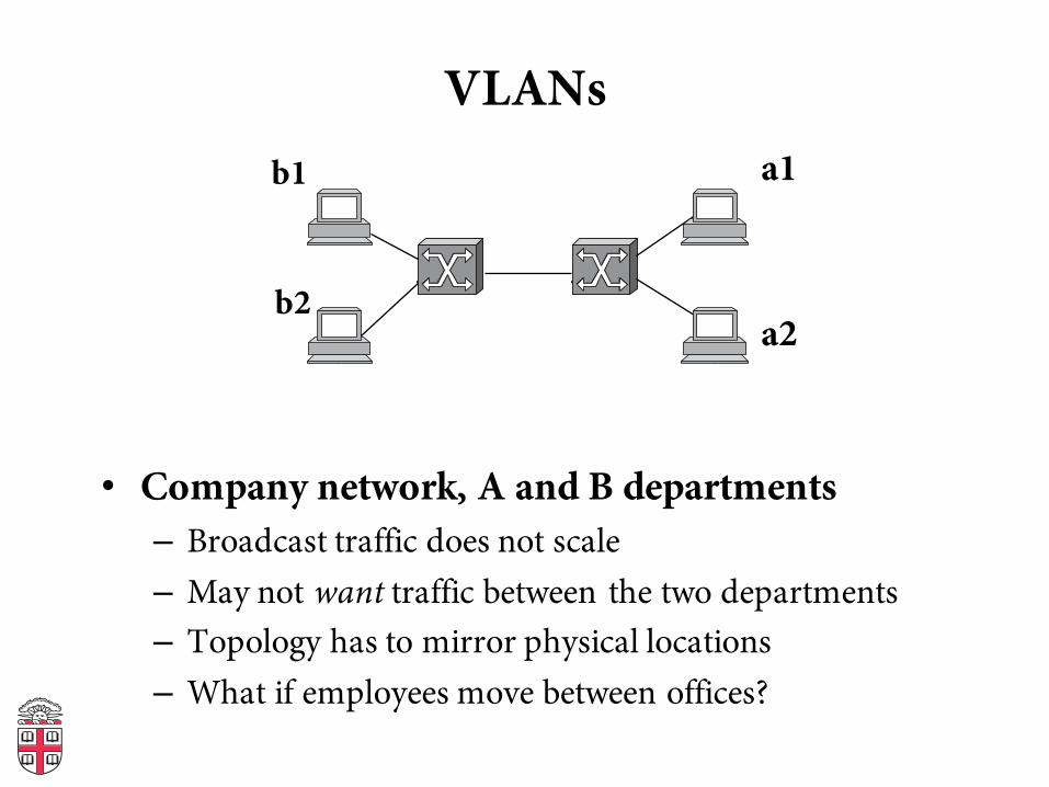
• Company network, A and B departments– Broadcast traffic does not scale– May not want traffic between the two departments– Topology has to mirror physical locations– What if employees move between offices?
b1
b2
a1
a2
VLANs
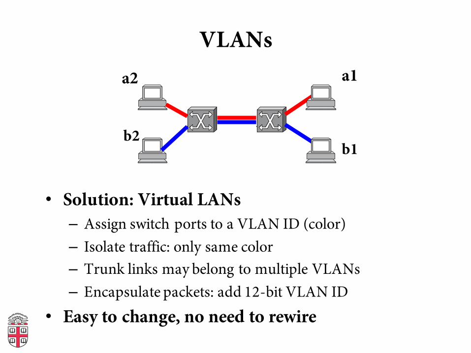
• Solution: Virtual LANs– Assign switch ports to a VLAN ID (color)– Isolate traffic: only same color– Trunk links may belong to multiple VLANs– Encapsulate packets: add 12-bit VLAN ID
• Easy to change, no need to rewire
a2
b2
a1
b1
Generic Switch Architecture
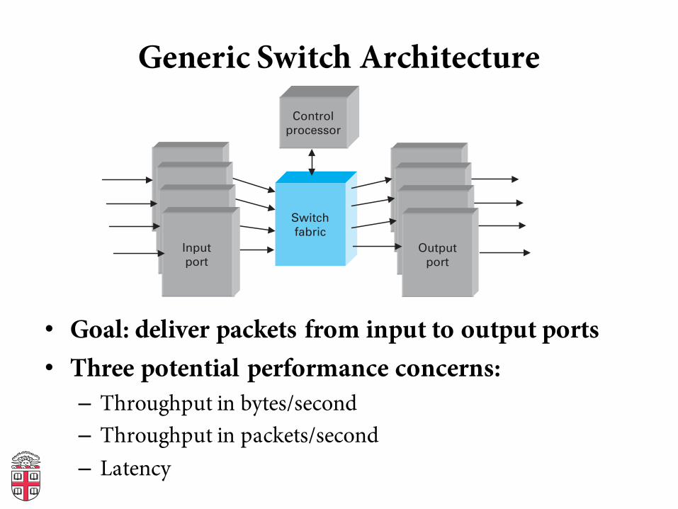
• Goal: deliver packets from input to output ports• Three potential performance concerns:– Throughput in bytes/second– Throughput in packets/second– Latency
Generic switch architecture
Switch fabric
Control processor
Output port
Input port
• Goal: deliver packets from input to output ports
• Three potential performance concerns:- Throughput in terms of bytes/time
- Throughput in terms of packets/time
- Latency
Shared Memory Switch
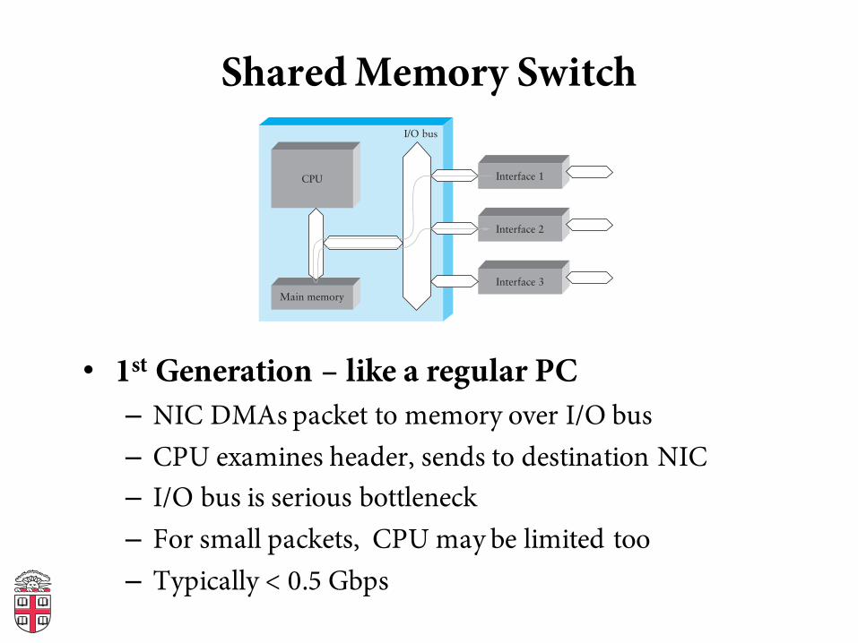
• 1st Generation – like a regular PC– NIC DMAs packet to memory over I/O bus– CPU examines header, sends to destination NIC– I/O bus is serious bottleneck– For small packets, CPU may be limited too– Typically < 0.5 Gbps
I/O bus
Interface 1
Interface 2
Interface 3
CPU
Main memory
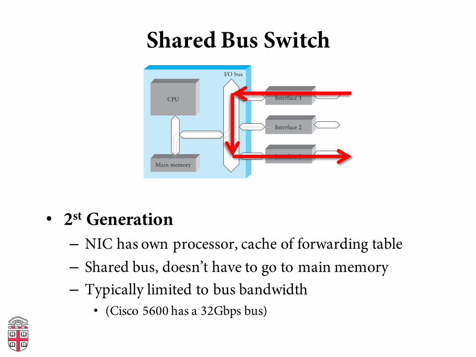
Shared Bus Switch
• 2st Generation– NIC has own processor, cache of forwarding table– Shared bus, doesn’t have to go to main memory– Typically limited to bus bandwidth
• (Cisco 5600 has a 32Gbps bus)
I/O bus
Interface 1
Interface 2
Interface 3
CPU
Main memory
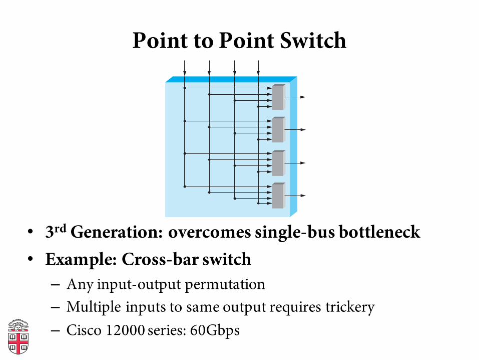
Point to Point Switch
• 3rd Generation: overcomes single-bus bottleneck• Example: Cross-bar switch– Any input-output permutation– Multiple inputs to same output requires trickery– Cisco 12000 series: 60Gbps
Cut through vs. Store and Forward
• Two approaches to forwarding a packet– Receive a full packet, then send to output port– Start retransmitting as soon as you know output port,
before full packet• Cut-through routing can greatly decrease latency• Disadvantage– Can waste transmission (classic optimistic approach)
• CRC may be bad• If Ethernet collision, may have to send runt packet on output link
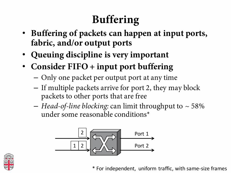
Buffering• Buffering of packets can happen at input ports,
fabric, and/or output ports• Queuing discipline is very important• Consider FIFO + input port buffering– Only one packet per output port at any time– If multiple packets arrive for port 2, they may block
packets to other ports that are free– Head-of-line blocking: can limit throughput to ~ 58%
under some reasonable conditions*
2
21
Port1
Port2
*Forindependent, uniformtraffic,withsame-sizeframes
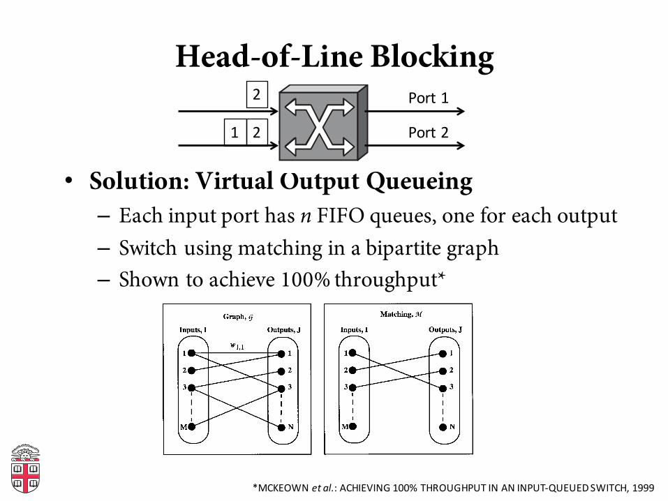
Head-of-Line Blocking
• Solution: Virtual Output Queueing– Each input port has n FIFO queues, one for each output– Switch using matching in a bipartite graph– Shown to achieve 100% throughput*
2
21
Port1
Port2
1262 IEEE TRANSACTIONS ON COMMUNICATIONS, VOL. 47, NO. 8, AUGUST 1999
(a) (b)
Fig. 2. Define as an undirected graph connecting the set of vertices with the set of edges . The edge connecting verticesand has an associated weight denoted . Graph is bipartite if the set of inputs and outputspartition such that every edge has one end in and one end in . Matching on is any subset of such that no two edges in have acommon vertex. A maximum matching algorithm is one that finds the matching with the maximum total size or total weight. (a) Example offor and . (b) Example of matching on .
necessarily desirable. First, under admissible traffic, it canlead to instability and unfairness, particularly for nonuniformtraffic patterns. To demonstrate this behavior, Fig. 3 showsan example of a potentially unstable 3 3 switch with justfour active flows,3 and scheduled using the maximum sizematching algorithm. It is assumed that ties are broken byselecting among alternatives with equal probability. Arrivalsto the switch are i.i.d. Bernoulli arrivals and each flow hasarrivals at rate , where . Even though thetraffic is admissible, it is straightforward to show that theswitch can be unstable for sufficiently small . Consider theevent that at slot , both and have arrivalswith probability and ,in which case input 1 receives service with probability 2/3.Therefore, the total rate at which input 1 receives service isat most
But the arrival rate to input 1 is , so if
(which holds for ), then the switch is unstable andthe traffic cannot be sustained by the maximum size matchingalgorithm.Second, under inadmissible traffic, the maximum size
matching algorithm can lead to starvation. An example ofthis behavior is shown in Fig. 4 for a 2 2 switch. It isclear that because all three queues are permanently occupied,
3 It can also be shown that a 2 2 switch with nonuniform traffic can beunstable when scheduled using a maximum size matching algorithm. However,our proof is more complex and is omitted here.
Fig. 3. An example of instability under admissible traffic using a maximumsize matching algorithm for a 3 3 switch with nonuniform traffic.
Fig. 4. Under an inadmissible workload, the maximum size matching willalways serve just two queues, starving the flow from input 1 to output 1.
the algorithm will always select the “cross” traffic: input 1 tooutput 2 and input 2 to output 1. It is worth noting that thepractical scheduling algorithms described previously attemptto approximate a maximum size matching [1], [2], [4], [14],[22]. It is therefore not surprising that these algorithms performwell when the traffic is uniform, but perform less well whenthe traffic is nonuniform.
IV. MAXIMUM WEIGHT MATCHINGSThe maximum weight matching for a bipartite graph
is one that maximizes and can be foundby solving an equivalent network flow problem. The mostefficient known algorithm for solving this problem convergesin running time [20].
*MCKEOWNetal.:ACHIEVING100%THROUGHPUTINANINPUT-QUEUEDSWITCH,1999
Coming Up
• Connecting multiple networks: IP and the Network Layer