csc-211 multifunction protection ied engineering and operation … · 2012-09-21 · for the...
TRANSCRIPT

CSC-211
Multifunction Protection IED
Engineering and Operation
Manual
Version:V1.00
Doc. Code: 0SF.461.046(E)
Issued Date:2012.8
Copyright owner: Beijing Sifang Automation Co., Ltd
Note: The company keeps the right to perfect the instruction. If equipments do not agree with
the instruction at anywhere, please contact our company in time. We will provide you with
corresponding service.
® is registered trademark of Beijing Sifang Automation Co., Ltd.
We reserve all rights to this document, even in the event that a patent is issued and a different commercial proprietary right is registered. Improper use, in particular reproduction and dissemination to third parties, is not permitted.
This document has been carefully checked. If the user nevertheless detects any errors, he is asked to notify us as soon as possible.
The data contained in this manual is intended solely for the IED description and is not to be deemed to be a statement of guaranteed properties. In the interests of our customers, we constantly seek to ensure that our products are developed to the latest technological standards as a result it is possible that there may be some differences between the hardware/software product and this information product.
Manufacturer: Beijing Sifang Automation Co., Ltd.
Tel: +86 10 62962554, +86 10 62961515 ext. 8998 Fax: +86 10 82783625 Email: [email protected] Website: http://www.sf-auto.com
Add: No.9, Shangdi 4th Street, Haidian District, Beijing, P.R.C.100085

Preface
Purpose of this manual
This manual describes operation, installation, commissioning, protection test
and putting the IED into service. The manual includes the following chapters:
Introduction, this chapter presents the basic content and have a brief
introduction of this manual
Local human machine interface, this chapter presents the configuration
of HMI interface and how to use the HMI
Installing the IED, this chapter introduces the procedure to install IED and
how to check that the IED is properly connected to the protection system
Read and change setting, this chapter introduces how to read and
change the setting value via LHMI or software tool, and switch the setting
value group
Testing the communication connection and time synchronization, this
chapter presents how to test the communication port connection and
introduces how to test time synchronization
IED testing, this chapter contains that what should be tested and how to
test the IED
Operating maintenance, this chaper describes the items for maintenance
and how to maintain the IED when operating
Transportion and storage, this chapter presents how to transport and
store the IED
Appendix, this chapter presents the significant data and diagram of the
IED
Target audience
This manual mainly face to installation engineer, commissioning engineer and
operation engineer with perfessional electric and electrical knowledge, rich
experience in protection function, using protection IED, test IED, responsible

for the installation, commissioning, maintenance and taking the protection
IED in and out of normal service.
Applicability of this manual
This manual is valid for CSC-211 Multifunction Protection IED.
Technical support
In case of further questions concerning the CSC family, please contact Sifang
compay or your local Sifang representative.
Safety information
Strictly follow the company and international safety regulations.
Working in a high voltage environment requires serious approch to
aviod human injuries and damage to equipment
Do not touch any circuitry during operation. Potentially lethal
voltages and currents are present
Avoid to touching the circuitry when covers are removed. The IED
contains electirc circuits which can be damaged if exposed to static
electricity. Lethal high voltage circuits are also exposed when covers
are removed
Using the isolated test pins when measuring signals in open circuitry.
Potentially lethal voltages and currents are present
Never connect or disconnect wire and/or connector to or from IED
during normal operation. Dangerous voltages and currents are
present. Operation may be interrupted and IED and measuring
circuitry may be damaged
Always connect the IED to protective earth regardless of the

operating conditions. Operating the IED without proper earthing may
damage both IED and measuring circuitry and may cause injuries in
case of an accident.
Do not disconnect the secondary connection of current transformer
without short-circuiting the transformer’s secondary winding.
Operating a current transformer with the secondary winding open will
cause a high voltage that may damage the transformer and may
cause injuries to humans.
Do not remove the screw from a powered IED or from an IED
connected to power circuitry. Potentially lethal voltages and currents
are present
Using the certified conductive bags to transport PCBs (modules).
Handling modules with a conductive wrist strap connected to
protective earth and on an antistatic surface. Electrostatic discharge
may cause damage to the module due to electronic circuits are
sensitive to this phenomenon
Do not connect live wires to the IED, internal circuitry may be
damaged
When replacing modules using a conductive wrist strap connected to
protective earth. Electrostatic discharge may damage the modules
and IED circuitry
When installing and commissioning, take care to avoid electrical
shock if accessing wiring and connection IEDs
Changing the setting value group will inevitably change the IEDs
operation. Be careful and check regulations before making the
change
Contents
Chapter 1 IED Introduction ............................................................................................................... 1
Chapter 2 Local human machine interface .................................................................................... 3
1 Introduction ....................................................................................................................................... 4
2 Liquid crystal display (LCD) ........................................................................................................... 5
3 LED .................................................................................................................................................... 6
4 Keyboard ........................................................................................................................................... 7
5 IED menu .......................................................................................................................................... 8
5.1 Menu construction ........................................................................................................... 8
5.2 Operation status ............................................................................................................. 10
5.3 Operation configuration ................................................................................................ 10
5.4 Settings ........................................................................................................................... 10
5.5 Report .............................................................................................................................. 10
5.6 Communication configuration ...................................................................................... 11
5.7 Testing ............................................................................................................................. 11
5.8 Device setup ................................................................................................................... 11
5.9 Device information ......................................................................................................... 13
Chapter 3 Installing IED .................................................................................................................. 15
1 Unpacking and checking the IED ................................................................................................ 16
2 Installing the IED ............................................................................................................................ 17
3 IED connection ............................................................................................................................... 18
3.1 IED connector ................................................................................................................. 18
3.1.1 Introduction ............................................................................................................. 18
3.1.2 Terminals of Analogue Input Module (AIM) ........................................................ 19
3.1.3 Terminals of Fast binary Input & Output Module (FIO) .................................... 23
3.1.4 Terminals of Fast binary Output Module (FOM) ................................................ 24
3.1.5 Terminals of Binary Input & Output module (BIO)............................................. 25
3.1.6 Terminals of CPU module (CPU) ......................................................................... 26
3.1.7 Terminals of Power Supply Module (PSM) ........................................................ 27
3.1.8 RS232 port .............................................................................................................. 28
3.2 Connecting to protective earth ..................................................................................... 28
3.3 Connecting the power supply module ........................................................................ 28
3.4 Connecting to CT and VT circuits ............................................................................... 28
3.5 Connecting the binary inputs and outputs.................................................................. 28
3.6 Making the screen connection ..................................................................................... 29
3.7 RS485 and RS232 ports connection .......................................................................... 29
3.7.1 RS485 port connection ......................................................................................... 29
3.7.2 RS232 port connection ......................................................................................... 30
3.8 Connecting the GPS...................................................................................................... 30
4 Checking before energizing ......................................................................................................... 32
4.1 Introduction ..................................................................................................................... 32

4.2 Checking the protective earth connection ................................................................. 32
4.3 Checking the power supply connection ..................................................................... 32
4.4 Checking the CT and VT circuits connection ............................................................ 32
4.4.1 Checking the CT circuits connection .................................................................. 32
4.4.2 Checking the VT connection ................................................................................ 33
4.5 Checking the binary input and output connection .................................................... 33
4.5.1 Checking the binary input connection ................................................................ 33
4.5.2 Checking the binary output connection .............................................................. 34
4.6 Checking the screened cables connection ................................................................ 34
4.7 Checking the S485 and RS232 port connectios ....................................................... 34
4.7.1 Checking the RS485 port connection ................................................................. 34
4.7.2 Checking RS232 port connection ....................................................................... 34
4.8 Checking GPS connection ........................................................................................... 34
4.9 Checking the insulation voltage and insulation resistance ..................................... 34
4.9.1 Checking the insulation voltage .......................................................................... 34
4.9.2 Checking the insulation resistance ..................................................................... 35
5 Checking after energizing ............................................................................................................ 36
5.1 Introduction ..................................................................................................................... 36
5.2 Test LCD ......................................................................................................................... 36
5.3 Test the keyboard .......................................................................................................... 36
5.4 Setting the IED time ...................................................................................................... 36
5.5 Checking the software and hardware version ........................................................... 37
Chapter 4 Read and change setting ............................................................................................. 39
1 Read and change the setting vaule ............................................................................................ 40
1.1 Read and change the setting value via LHMI ........................................................... 40
1.1.1 Introduction ............................................................................................................. 40
1.1.2 Communication parameter ................................................................................... 40
1.1.3 Setting values, binary settings and soft connetors for protection function ... 41
2 Switching the setting group .......................................................................................................... 43
2.1 Introduction ..................................................................................................................... 43
2.2 Method for switching setting group via LHMI ............................................................ 43
2.3 Method for switching setting group via binary input ................................................. 43
Chapter 5 Testing the communication connection and time synchronization ......................... 45
1 Testing the communication connection ...................................................................................... 46
1.1 Testing the Ethernet communication .......................................................................... 46
1.1.1 Testing the electrical Ethernet communication ................................................. 46
1.1.2 Testing the optical Ethernet communication ...................................................... 46
1.2 Testing the RS485 port................................................................................................. 46
1.3 Testing the RS232 port................................................................................................. 46
2 Testing the time synchronization ................................................................................................. 48
2.1 Network mode ................................................................................................................ 48
2.2 IRIG-B mode .................................................................................................................. 48
Chapter 6 IED testing ...................................................................................................................... 49
1 Introduction ..................................................................................................................................... 50
2 Points for attention during testing................................................................................................ 52
3 Preparing for test ........................................................................................................................... 54
3.1 Introduction ..................................................................................................................... 54
3.2 Connecting test equipment to IED .............................................................................. 54
4 Testing the power supply .............................................................................................................. 56
4.1 Checking the self-startup performance ...................................................................... 56
4.2 DC power on and power off testing............................................................................. 56
4.3 Checking the expiry date of power supply ................................................................. 56
5 Checking the analog channel ...................................................................................................... 57
5.1 Checking and adjusting the zero drift ......................................................................... 57
5.2 Checking and calibrating .............................................................................................. 57
6 Testing binary input ....................................................................................................................... 59
7 Testing binary output ..................................................................................................................... 60
8 Verifying the IED functions ........................................................................................................... 61
8.1 Overcurrent protection .................................................................................................. 61
8.1.1 Verifying the settings ............................................................................................. 61
8.1.2 Completing the test ................................................................................................ 68
8.1.3 Reference setting list for test ............................................................................... 68
8.2 Earth fault protection ..................................................................................................... 70
8.2.1 Verifying the settings ............................................................................................. 70
8.2.2 Completing the test ................................................................................................ 76
8.2.3 Reference setting list for test ............................................................................... 76
8.3 Sensitive earth fault protection .................................................................................... 78
8.3.1 Verifying the settings ............................................................................................. 78
8.3.2 Completing the test ................................................................................................ 83
8.3.3 Reference setting list for test ............................................................................... 83
8.4 Negative sequence overcurrent protection ................................................................ 85
8.4.1 Verifying the settings ............................................................................................. 85
8.4.2 Completing the test ................................................................................................ 88
8.4.3 Reference setting list for test ............................................................................... 88
8.5 Switch-onto-fault protection .......................................................................................... 89
8.5.1 Verifying the settings ............................................................................................. 89
8.5.2 Completing the test ................................................................................................ 92
8.5.3 Reference setting list for test ............................................................................... 92
8.6 Overload protection ....................................................................................................... 92
8.6.1 Verifying the settings ............................................................................................. 93
8.6.2 Completing the test ................................................................................................ 95
8.6.3 Reference setting list for test ............................................................................... 95
8.7 Overvoltage protection .................................................................................................. 95
8.7.1 Verifying the settings ............................................................................................. 96
8.7.2 Completing the test .............................................................................................. 100
8.7.3 Reference setting list for test ............................................................................. 100
8.8 Undervoltage protection .............................................................................................. 101
8.8.1 Verifying the settings ........................................................................................... 101

8.8.2 Completing the test ............................................................................................. 107
8.8.3 Reference setting list for test ............................................................................. 107
8.9 Thermal overload protection ...................................................................................... 108
8.9.1 Verifying the settings ........................................................................................... 108
8.9.2 Completing the test ............................................................................................. 113
8.9.3 Reference setting list for test ............................................................................. 113
8.10 Displacement voltage protection ............................................................................... 114
8.10.1 Verifying the settings ........................................................................................... 114
8.10.2 Completing the test ............................................................................................. 117
8.10.3 Reference setting list for test ............................................................................. 118
8.11 Circuit breaker failure protection ............................................................................... 118
8.11.1 Verifying the settings of stage 1 of CBF protection ........................................ 119
8.11.2 Completing the test ............................................................................................. 122
8.11.3 Reference setting list for test ............................................................................. 123
8.12 Dead zone protection .................................................................................................. 123
8.12.1 Verifying the settings ........................................................................................... 124
8.12.2 Completing the test ............................................................................................. 125
8.12.3 Reference setting list for test ............................................................................. 125
8.13 Synchro-check and energizing check function ....................................................... 125
8.13.1 Verifying the settings ........................................................................................... 125
8.13.2 Completing the test ............................................................................................. 132
8.13.3 Reference setting list for test ............................................................................. 132
8.14 Auto-recloser ................................................................................................................ 134
8.14.1 Verifying the settings ........................................................................................... 134
8.14.2 Completing the test ............................................................................................. 134
8.14.3 Reference setting list for test ............................................................................. 135
8.15 Low(under) frequency load shedding protection .................................................... 137
8.15.1 Verifying the settings ........................................................................................... 137
8.15.2 Completing the test ............................................................................................. 141
8.15.3 Reference setting list for test ............................................................................. 141
8.16 Low voltage load shedding protection ...................................................................... 142
8.16.1 Verifying the settings ........................................................................................... 142
8.16.2 Completing the test ............................................................................................. 146
8.16.3 Reference setting list for test ............................................................................. 146
8.17 Overload load shedding protection ........................................................................... 147
8.17.1 Verifying the settings ........................................................................................... 147
8.17.2 Completing the test ............................................................................................. 150
8.17.3 Reference setting list for test ............................................................................. 151
8.18 Unbalance protection .................................................................................................. 151
8.18.1 Verifying the settings ........................................................................................... 152
8.18.2 Completing the test ............................................................................................. 155
8.18.3 Reference setting list for test ............................................................................. 155
8.19 Under current monitoring ........................................................................................... 156
8.19.1 Verifying the settings ........................................................................................... 156
8.19.2 Completing the test .............................................................................................. 158
8.19.3 Reference setting list for test ............................................................................. 158
8.20 Current overload monitoring....................................................................................... 158
8.20.1 Verifying the settings ........................................................................................... 158
8.20.2 Completing the test .............................................................................................. 161
8.20.3 Reference setting list for test ............................................................................. 161
8.21 Control circuit faulty supervising ................................................................................ 162
8.21.1 Verifying the settings ........................................................................................... 162
8.21.2 Completing the test .............................................................................................. 163
8.21.3 Reference setting list for test ............................................................................. 163
8.22 Current transformer secondary circuit supervision ................................................. 164
8.22.1 Verifying the settings ........................................................................................... 164
8.22.2 Completing the test .............................................................................................. 165
8.22.3 Reference setting list for test ............................................................................. 165
8.23 Voltage transformer secondary circuit supervision ................................................. 165
8.23.1 Verifying the settings ........................................................................................... 166
8.23.2 Completing the test .............................................................................................. 173
8.23.3 Reference setting list for test ............................................................................. 173
8.24 Monitoring function ...................................................................................................... 174
8.24.1 Auxiliary contact of circuit breaker monitoring ................................................. 174
9 Checking before operation ......................................................................................................... 176
9.1 Checking the LED ........................................................................................................ 176
9.2 Checking the display on LCD..................................................................................... 176
9.3 Checking the clock ...................................................................................................... 176
9.4 Checking the voltage and current ............................................................................. 176
9.5 Checking the setting group ........................................................................................ 176
9.6 Checking the setting .................................................................................................... 176
9.7 Checking the binary input ........................................................................................... 177
9.8 Checking the normal operation mode ....................................................................... 177
9.8.1 Trip and close test with the circuit breaker ....................................................... 177
9.9 Put into operation ......................................................................................................... 177
Chapter 7 Operating maintenance .............................................................................................. 179
1 Attentions during operating ........................................................................................................ 180
2 Routine checking ......................................................................................................................... 182
3 Periodical checking ..................................................................................................................... 183
4 The alarm information ................................................................................................................. 184
4.1 Alarm information class I and the description .......................................................... 184
4.2 Alarm information class II and the description for M1 ............................................ 184
Chapter 8 Transportation and storage ........................................................................................ 189
1 Transportion.................................................................................................................................. 190
2 Storage .......................................................................................................................................... 191
Chapter 9 Appendix ....................................................................................................................... 193
1 Arrangement diagram of modules ............................................................................................. 194
2 Typical diagram ............................................................................................................................ 195
错误!未找到引用源。 IED Introduction
1
Chapter 1 IED Introduction
About this chapter
This chapter presents the overview of the operation and
engineering about the IED.
错误!未找到引用源。 IED Introduction
2
The Human Machine Interface (HMI) on the IED provides an ideal
mechanism for the day to day operation and even advanced use of the IED.
The keyboard, LCD and LEDs on the front of the IED are what constitute the
HMI. Troubleshooting, monitoring, setting and configuring are all possible via
this interface. Through the screens and menu elements available, as well as
the keypad, the user is able to navigate throughout the menu structure and
move from screen to screen.
The IED is unpacked and visually checked. The connection to the protection
system has to be checked in order to verify that the installation is successful.
The settings for each function must be calculated before the commissioning
task. The functions setting menu have been listed in detail so that the user
can find and change the required settings directly and correctly. For the
different application, the IED can be performed conveniently through
switching the setting group.
For the functions included in the IED can be tested by users, the testing
procedure have been listed as reference to verify that protection function
operate correctly.
After the IED is in service, some checking items also need to be done for
maintenance in order to ensure that the IED is in good condition during
operation, some suggestions have been preset as reference and the user can
perform some other checking items according to the relevant regulations.

错误!未找到引用源。 Local human machine interface
3
Chapter 2 Local human machine
interface
About this chapter
This chapter describes the structure of human-machine
interface (HMI), LCD, LED, keyboard, RS232 and IED menu.
Instruction on how to operate with keys, how to configure the
LED and menu information introduction.

错误!未找到引用源。 Local human machine interface
4
1 Introduction
The HMI is simple and easy to be used for routine operation, the front panel
of the HMI consists of LCD, LED and keyboard. As shown in the following
picture, the setting, configuration, monitoring, maintenance and fault analysis
can be performed in HMI.
2
1
3
4
5 6
7
CSC-211
Figure 1 Front plate
1. Liquid crystal display (LCD)
2. LEDs
3. Arrow keys
4. Reset key
5. Quit key
6. Set key
7. RS232 communication port

错误!未找到引用源。 Local human machine interface
5
2 Liquid crystal display (LCD)
When operating keys are pressed or in the case of IED alarming or operating
report appearance, the back light will turn on automatically until the preset
time delay elapse after the latest operation or alarm.

错误!未找到引用源。 Local human machine interface
6
3 LED
There are 11 LEDs on the left side of the LCD. The definition for each LED is
shown as following table.
Table 1 HMI keys on the front of the IED
NO. Definition Color Explanation
1. Run/Alarm Green The IED operate nomally
Red The alarm is issued
2. OC Green The overcurrent protection is enabled
Red The overcurrent protection has operated
3. EF Green The earth fault protection is enabled
Red The earth fault protection has operated
4. SEF Green The sensitive earth fault protection is enabled
Red The sensitive earth fault protection has operated
5. NSOC
Green The negative sequence overcurrent protection is enabled
Red The negative sequence overcurrent protection has
operated
6. CBF/DZ
Green The circuit breaker failure or dead zone protection is
enabled
Red The circuit breaker failure or dead zone protection has
operated
7. Themal OL Green The thermal overload protection is enabled
Red The thermal overload protection has operated
8. 3V0 Green The displacement voltage protection is enabled
Red The displacement voltage protection has operated
9. OV/UV Green The overvoltage or undervoltage protection is enabled
Red The overvoltage or undervoltage protection has operated
10. Load SHED Green The load shedding protection is enabled
Red The load shedding protection has operated
11. AR/MC Green The autorecloser or manual reclose function is enabled
Red The autorecloser or manual reclose function has operated
错误!未找到引用源。 Local human machine interface
7
4 Keyboard
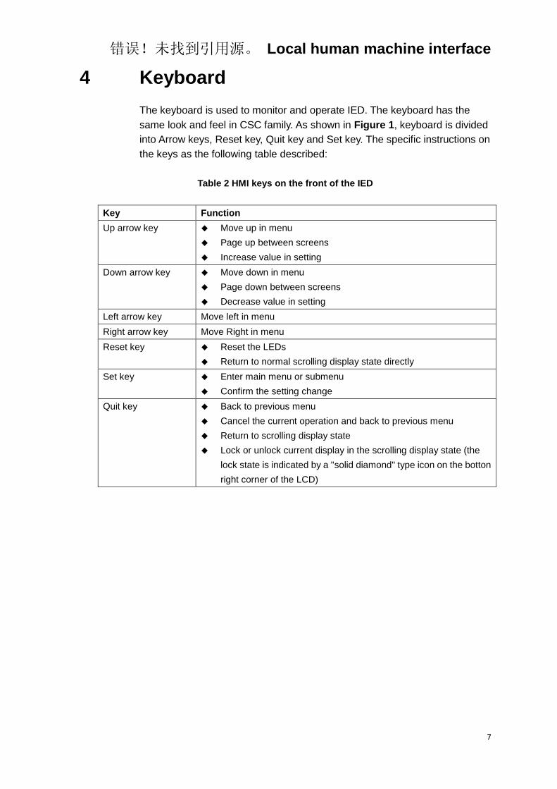
The keyboard is used to monitor and operate IED. The keyboard has the
same look and feel in CSC family. As shown in Figure 1, keyboard is divided
into Arrow keys, Reset key, Quit key and Set key. The specific instructions on
the keys as the following table described:
Table 2 HMI keys on the front of the IED
Key Function
Up arrow key Move up in menu
Page up between screens
Increase value in setting
Down arrow key Move down in menu
Page down between screens
Decrease value in setting
Left arrow key Move left in menu
Right arrow key Move Right in menu
Reset key Reset the LEDs
Return to normal scrolling display state directly
Set key Enter main menu or submenu
Confirm the setting change
Quit key Back to previous menu
Cancel the current operation and back to previous menu
Return to scrolling display state
Lock or unlock current display in the scrolling display state (the
lock state is indicated by a "solid diamond" type icon on the botton
right corner of the LCD)

错误!未找到引用源。 Local human machine interface
8
5 IED menu
5.1 Menu construction
OpStatus
OpConfig
Settings
Report
ComConf
Testing
DevSetup
DevInfo
Analog BI
Connect
GOOSEINF
Metering
Energy
Switch Time
Connect
Read Switch
Event
Remote
BO
BI
Zero
LED Test
Eth 1#
Operation
Version OpInfo
Serial
MainMenu
Eth 2#
GOO Ctrl GOOSESUB
GOO Ctrl
Write Delete
Alarm Clear
Wave
Monitor
Label
Accuracy
TestMode
Metering
Module
Remote
SysParam Backlit
错误!未找到引用源。 Local human machine interface
9
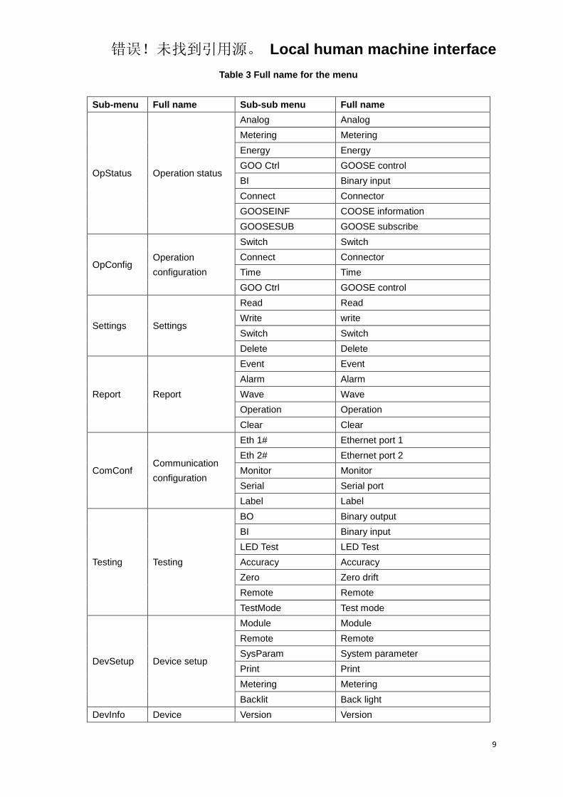
Table 3 Full name for the menu
Sub-menu Full name Sub-sub menu Full name
OpStatus Operation status
Analog Analog
Metering Metering
Energy Energy
GOO Ctrl GOOSE control
BI Binary input
Connect Connector
GOOSEINF COOSE information
GOOSESUB GOOSE subscribe
OpConfig Operation
configuration
Switch Switch
Connect Connector
Time Time
GOO Ctrl GOOSE control
Settings Settings
Read Read
Write write
Switch Switch
Delete Delete
Report Report
Event Event
Alarm Alarm
Wave Wave
Operation Operation
Clear Clear
ComConf Communication
configuration
Eth 1# Ethernet port 1
Eth 2# Ethernet port 2
Monitor Monitor
Serial Serial port
Label Label
Testing Testing
BO Binary output
BI Binary input
LED Test LED Test
Accuracy Accuracy
Zero Zero drift
Remote Remote
TestMode Test mode
DevSetup Device setup
Module Module
Remote Remote
SysParam System parameter
Print Print
Metering Metering
Backlit Back light
DevInfo Device Version Version

错误!未找到引用源。 Local human machine interface
10
Sub-menu Full name Sub-sub menu Full name
information OpInfo Operation information
5.2 Operation status
Sub menu Sub-sub menu Explanation
OpConfig
Analog Read the analog input of the IED
Metering Read the measurement analog input of the IED
Energy Read the energy inputs of the IED
GOO Ctrl Read the status of the GOOSE connector
BI Read the status of binary inputs
Connect Read the status of the connector
GOOSEINF Read the transmission of the report
GOOSESUB Read the information of the GOOSE
5.3 Operation configuration
Sub menu Sub-sub menu Explanation
OpConfig
Switch Switching setting group
Connect Enable or disable the protection function
Time Setting the current time of the IED
GOO Ctrl Function related GOOSE ON/OFF
5.4 Settings
Sub menu Sub-sub menu Explanation
Settings
Read Read the settings
Write Set the settings
Switch Switch setting group
Delete Delete settings
5.5 Report
Sub menu Sub-sub menu Explanation
Report
Event Display latest 40 event records
Alarm Display latest 40 alarm records
Wave Display latest 10 recording wave
Operation Display latest 40 IED operation records
Clear Clear all history reports saved by the IED and delete

错误!未找到引用源。 Local human machine interface
11
Sub menu Sub-sub menu Explanation
unnecessary test records before IED operation.
5.6 Communication configuration
Sub menu Sub-sub menu Explanation
ComConf
Eth 1# Set Ethernet port 1 in CPU module.
Eth 2# Set Ethernet port 2 in CPU module.
Monitor Set parameter related BIO module
Serial Serial 1 is used for SIO in panel, serial 2 is used for 485
port in CPU module and Serial 3 is reserved for dual
485 CPU module.
Label Set IED address (hex), STA name and Bay name
5.7 Testing
Sub menu Sub-sub
menu
Sub-sub-sub
menu
Explanation
Testing
BO Test the binary outputs
BI Test the binary inputs
LED Test Test the panel LED
Accuracy Test the analog quantites precision and
linearity
Zero View the zero drift
Remote
Event Report event report to monitor and SCADA
Alarm Report alarm report to monitor and SCADA
Signal Report the virtual SOE event to the monitor
and SCADA
Metering Report virtual remote measurement
over-limit event to the monitor and SCADA
TestMode
The IED enters/exit test state, and it will not
send the event information to the local
monitor and remote communication under
the test state. The IED should exit the test
status after the test completed
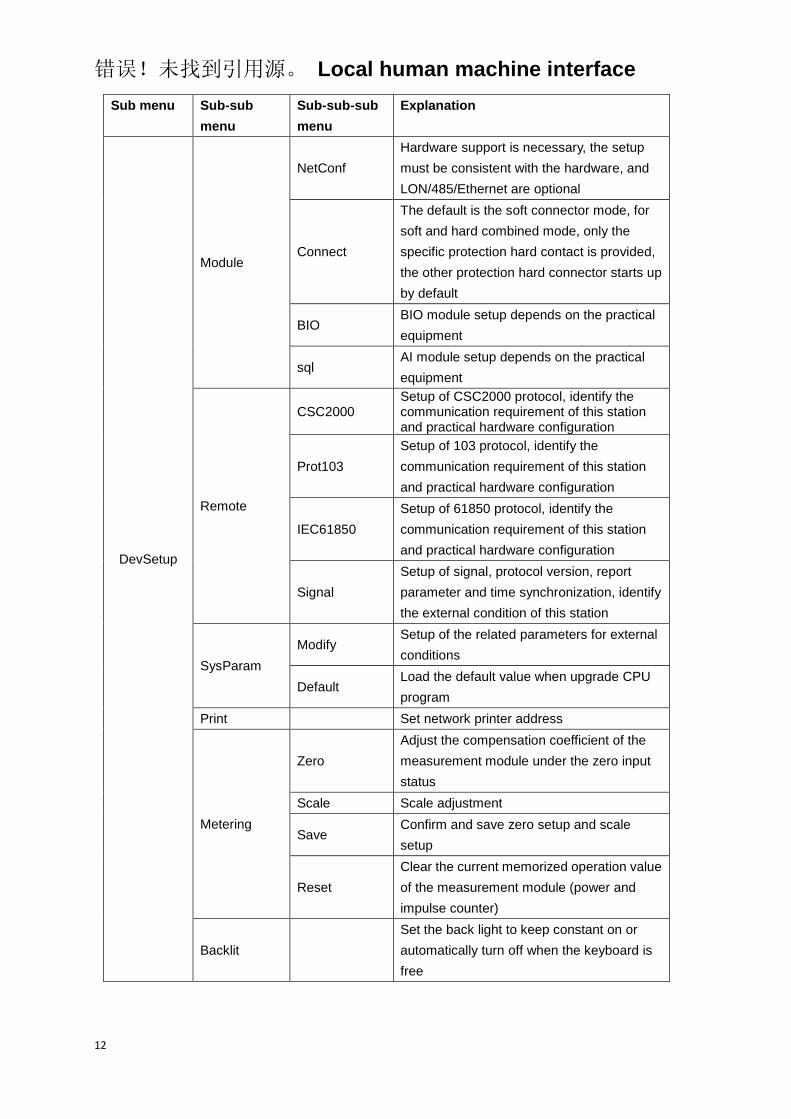
5.8 Device setup
Sub menu Sub-sub
menu
Sub-sub-sub
menu
Explanation
错误!未找到引用源。 Local human machine interface
12
Sub menu Sub-sub
menu
Sub-sub-sub
menu
Explanation
DevSetup
Module
NetConf
Hardware support is necessary, the setup
must be consistent with the hardware, and
LON/485/Ethernet are optional
Connect
The default is the soft connector mode, for
soft and hard combined mode, only the
specific protection hard contact is provided,
the other protection hard connector starts up
by default
BIO BIO module setup depends on the practical
equipment
sql AI module setup depends on the practical
equipment
Remote
CSC2000 Setup of CSC2000 protocol, identify the communication requirement of this station and practical hardware configuration
Prot103
Setup of 103 protocol, identify the
communication requirement of this station
and practical hardware configuration
IEC61850
Setup of 61850 protocol, identify the
communication requirement of this station
and practical hardware configuration
Signal
Setup of signal, protocol version, report
parameter and time synchronization, identify
the external condition of this station
SysParam
Modify Setup of the related parameters for external
conditions
Default Load the default value when upgrade CPU
program
Print Set network printer address
Metering
Zero
Adjust the compensation coefficient of the
measurement module under the zero input
status
Scale Scale adjustment
Save Confirm and save zero setup and scale
setup
Reset
Clear the current memorized operation value
of the measurement module (power and
impulse counter)
Backlit
Set the back light to keep constant on or
automatically turn off when the keyboard is
free
错误!未找到引用源。 Local human machine interface
13
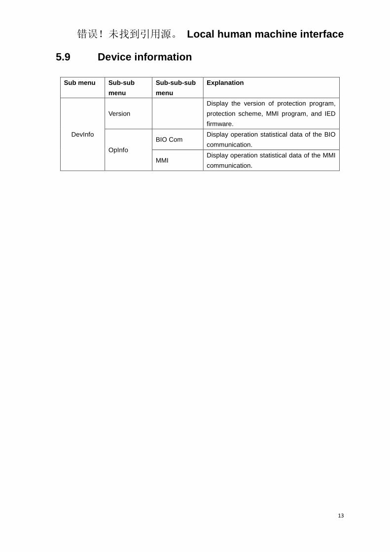
5.9 Device information
Sub menu Sub-sub
menu
Sub-sub-sub
menu
Explanation
DevInfo
Version
Display the version of protection program,
protection scheme, MMI program, and IED
firmware.
OpInfo
BIO Com Display operation statistical data of the BIO
communication.
MMI Display operation statistical data of the MMI
communication.

错误!未找到引用源。 Local human machine interface
14
错误!未找到引用源。 Installing IED
15
Chapter 3 Installing IED
About this chapter
This chapter describes how to install the protection IED,
introduces connection of the contactor, analogue quantities,
binary inputs and outputs and power supply, and what should to
do before and after energizing.
错误!未找到引用源。 Installing IED
16
1 Unpacking and checking the IED
Procedure:
1. Remove the transporting case
2. Visually inspect the IED
3. Check all items included in accordace with the delivery documents. Once
the IED has been started make sure that the software functions ordered
have been included in the delivery
4. Check for transport damages
If transport damage is discovered appropriate action must be taken
against the latest carrier and the latest SiFang office or representative
should be informed. If there are any discrepancies in relation to the
delivery documents, the SiFang company should be notified immediately
5. If the protection IED is repacked for transport again, the storage packing
of the IED must provide proper degree of protection against possible
damage, in accordance with the standard of IEC 60255-21-1 class 1 and
IEC 60255-21-2 class 1
错误!未找到引用源。 Installing IED
17
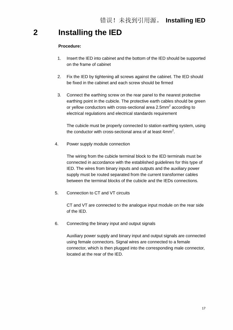
2 Installing the IED
Procedure:
1. Insert the IED into cabinet and the bottom of the IED should be supported
on the frame of cabinet
2. Fix the IED by tightening all screws against the cabinet. The IED should
be fixed in the cabinet and each screw should be firmed
3. Connect the earthing screw on the rear panel to the nearest protective
earthing point in the cubicle. The protective earth cables should be green
or yellow conductors with cross-sectional area 2.5mm2 according to
electrical regulations and electrical standards requirement
The cubicle must be properly connected to station earthing system, using
the conductor with cross-sectional area of at least 4mm2.
4. Power supply module connection
The wiring from the cubicle terminal block to the IED terminals must be
connected in accordance with the established guidelines for this type of
IED. The wires from binary inputs and outputs and the auxiliary power
supply must be routed separated from the current transformer cables
between the terminal blocks of the cubicle and the IEDs connections.
5. Connection to CT and VT circuits
CT and VT are connected to the analogue input module on the rear side
of the IED.
6. Connecting the binary input and output signals
Auxiliary power supply and binary input and output signals are connected
using female connectors. Signal wires are connected to a female
connector, which is then plugged into the corresponding male connector,
located at the rear of the IED.

错误!未找到引用源。 Installing IED
18
3 IED connection
3.1 IED connector
3.1.1 Introduction
The quantity and designation of connectors depend upon the ordering
information and application. The rear cover plates are prepared with enough
space for each configuration in ordering information.

错误!未找到引用源。 Installing IED
19
3.1.2 Terminals of Analogue Input Module (AIM)
A. Terminals of Analogue Input Module A series
I01
I02
I03
I04
I05
I06
I07
I08
I09
I10
I11
I12
Pro
tectio
nM
ete
rin
g
Figure 2 Terminals arrangement of AIM A
series
Table 4 Description of terminals of AIM A
series
Terminal Analogue
Input Remark
I01 I1 Star point
I02 I’1
I03 Null
I04 Null
I05 Null
I06 Null
I07 Null
I08 Null
I09 Null
I10 Null
I11 ImB Star point,
for metering
I12 I’mB For
metering
错误!未找到引用源。 Installing IED
20
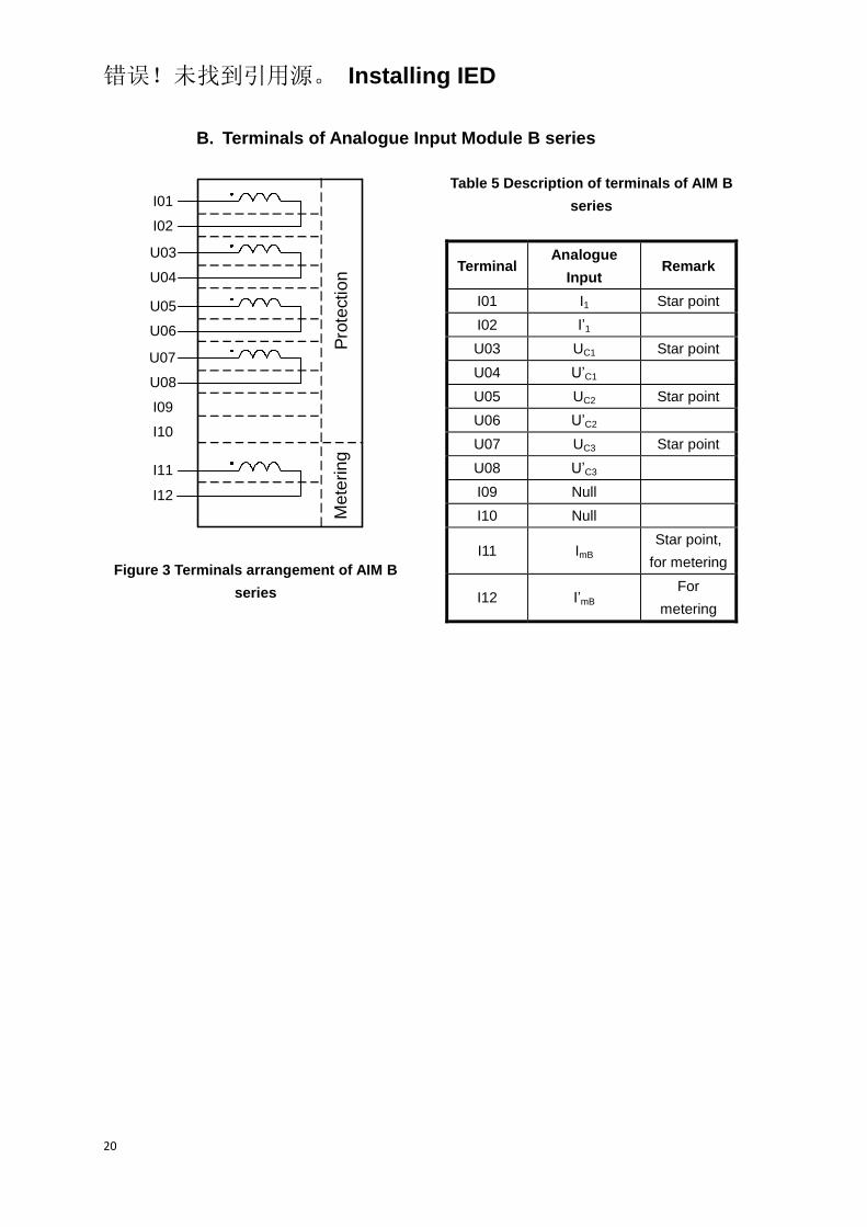
B. Terminals of Analogue Input Module B series
I01
I02
U03
U04
U05
U06
U07
U08
I09
I10
I11
I12
Pro
tectio
nM
ete
rin
g
Figure 3 Terminals arrangement of AIM B
series
Table 5 Description of terminals of AIM B
series
Terminal Analogue
Input Remark
I01 I1 Star point
I02 I’1
U03 UC1 Star point
U04 U’C1
U05 UC2 Star point
U06 U’C2
U07 UC3 Star point
U08 U’C3
I09 Null
I10 Null
I11 ImB Star point,
for metering
I12 I’mB For
metering
错误!未找到引用源。 Installing IED
21
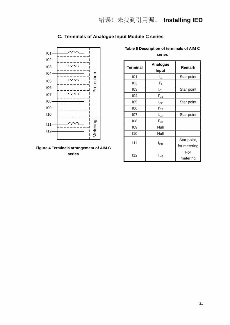
C. Terminals of Analogue Input Module C series
I01
I02
I03
I04
I05
I06
I07
I08
I09
I10
I11
I12
Pro
tection
Me
terin
g
Figure 4 Terminals arrangement of AIM C
series
Table 6 Description of terminals of AIM C
series
Terminal Analogue
Input Remark
I01 I1 Star point
I02 I’1
I03 IC1 Star point
I04 I’C1
I05 IC2 Star point
I06 I’C2
I07 IC3 Star point
I08 I’C3
I09 Null
I10 Null
I11 ImB Star point,
for metering
I12 I’mB For
metering
错误!未找到引用源。 Installing IED
22
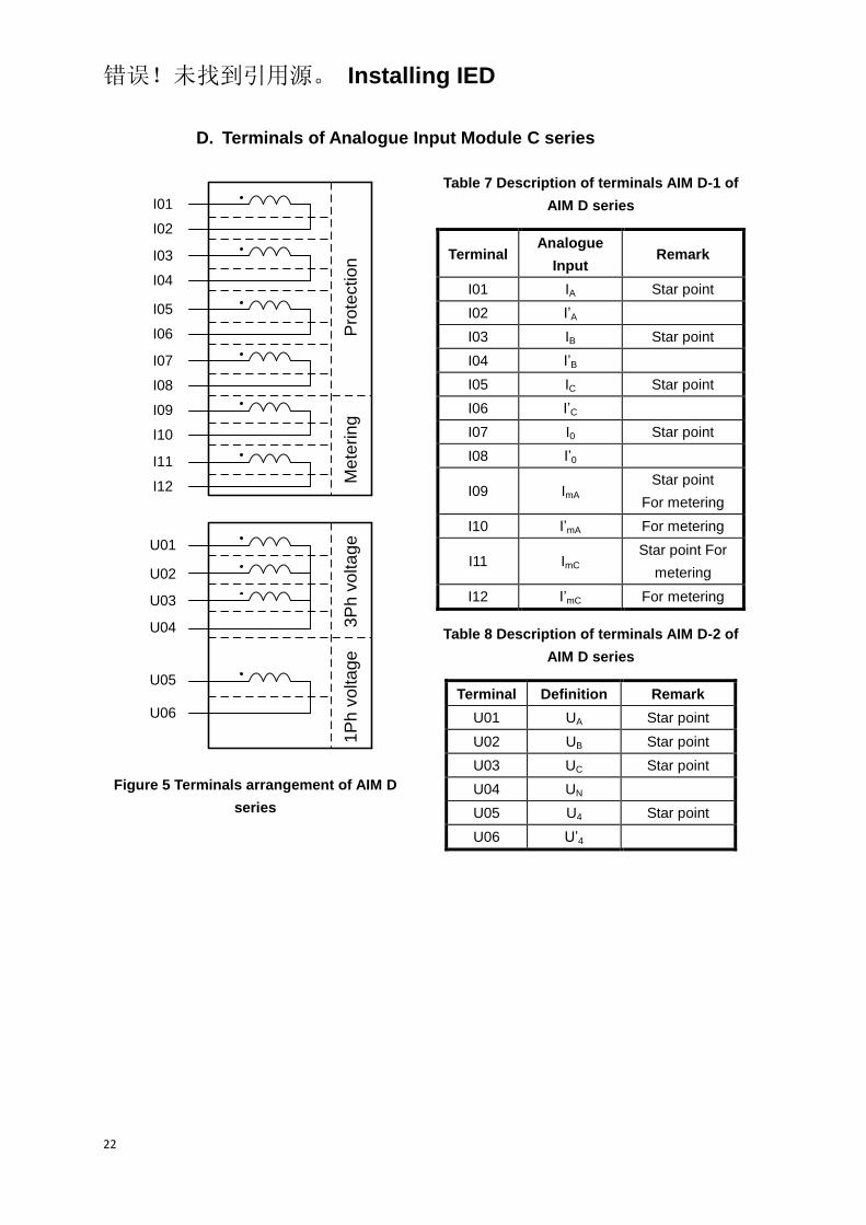
D. Terminals of Analogue Input Module C series
I01
I02
I03
I04
I05
I06
I07
I08
I09
I10
I11
I12
U01
U02
U03
U04
U05
U06
Pro
tectio
nM
ete
rin
g3
Ph
vo
lta
ge
1P
h v
olta
ge
Figure 5 Terminals arrangement of AIM D
series
Table 7 Description of terminals AIM D-1 of
AIM D series
Terminal Analogue
Input Remark
I01 IA Star point
I02 I’A
I03 IB Star point
I04 I’B
I05 IC Star point
I06 I’C
I07 I0 Star point
I08 I’0
I09 ImA Star point
For metering
I10 I’mA For metering
I11 ImC Star point For
metering
I12 I’mC For metering
Table 8 Description of terminals AIM D-2 of
AIM D series
Terminal Definition Remark
U01 UA Star point
U02 UB Star point
U03 UC Star point
U04 UN
U05 U4 Star point
U06 U’4
错误!未找到引用源。 Installing IED
23
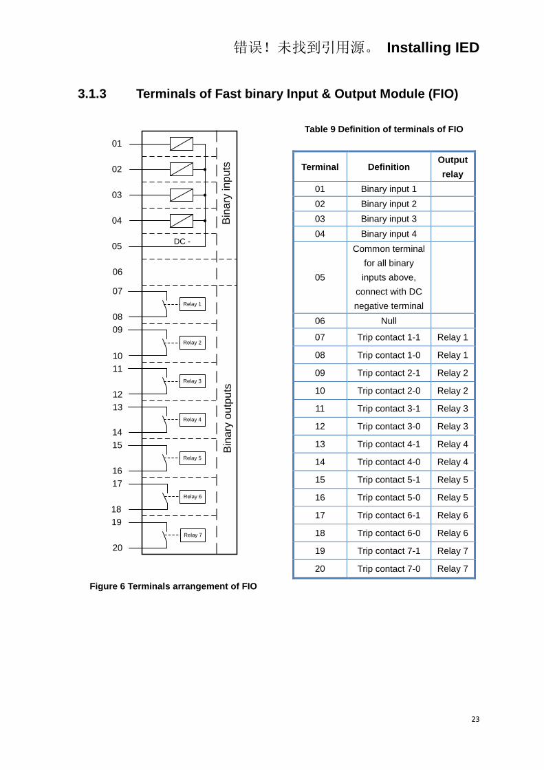
3.1.3 Terminals of Fast binary Input & Output Module (FIO)
01
02
03
05
06
07
08
09
10
11
12
04
13
14
15
16
17
18
19
20
DC -
Relay 7
Relay 6
Relay 5
Relay 4
Relay 3
Relay 2
Relay 1
Bin
ary
in
pu
tsB
ina
ry o
utp
uts
Figure 6 Terminals arrangement of FIO
Table 9 Definition of terminals of FIO
Terminal Definition Output
relay
01 Binary input 1
02 Binary input 2
03 Binary input 3
04 Binary input 4
05
Common terminal
for all binary
inputs above,
connect with DC
negative terminal
06 Null
07 Trip contact 1-1 Relay 1
08 Trip contact 1-0 Relay 1
09 Trip contact 2-1 Relay 2
10 Trip contact 2-0 Relay 2
11 Trip contact 3-1 Relay 3
12 Trip contact 3-0 Relay 3
13 Trip contact 4-1 Relay 4
14 Trip contact 4-0 Relay 4
15 Trip contact 5-1 Relay 5
16 Trip contact 5-0 Relay 5
17 Trip contact 6-1 Relay 6
18 Trip contact 6-0 Relay 6
19 Trip contact 7-1 Relay 7
20 Trip contact 7-0 Relay 7
错误!未找到引用源。 Installing IED
24
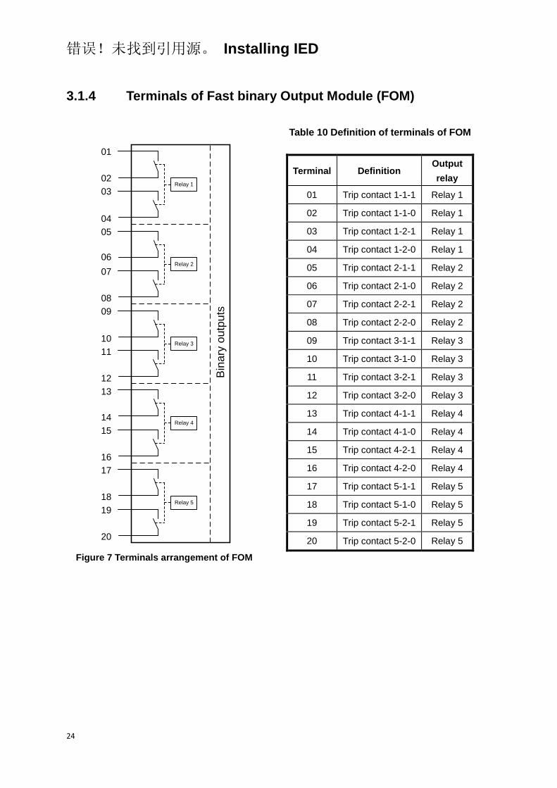
3.1.4 Terminals of Fast binary Output Module (FOM)
Relay 5
Relay 4
Relay 3
Relay 2
Relay 1
06
07
08
09
10
11
12
13
14
15
16
17
18
19
20
01
02
03
04
05
Bin
ary
ou
tpu
ts
Figure 7 Terminals arrangement of FOM
Table 10 Definition of terminals of FOM
Terminal Definition Output
relay
01 Trip contact 1-1-1 Relay 1
02 Trip contact 1-1-0 Relay 1
03 Trip contact 1-2-1 Relay 1
04 Trip contact 1-2-0 Relay 1
05 Trip contact 2-1-1 Relay 2
06 Trip contact 2-1-0 Relay 2
07 Trip contact 2-2-1 Relay 2
08 Trip contact 2-2-0 Relay 2
09 Trip contact 3-1-1 Relay 3
10 Trip contact 3-1-0 Relay 3
11 Trip contact 3-2-1 Relay 3
12 Trip contact 3-2-0 Relay 3
13 Trip contact 4-1-1 Relay 4
14 Trip contact 4-1-0 Relay 4
15 Trip contact 4-2-1 Relay 4
16 Trip contact 4-2-0 Relay 4
17 Trip contact 5-1-1 Relay 5
18 Trip contact 5-1-0 Relay 5
19 Trip contact 5-2-1 Relay 5
20 Trip contact 5-2-0 Relay 5
错误!未找到引用源。 Installing IED
25
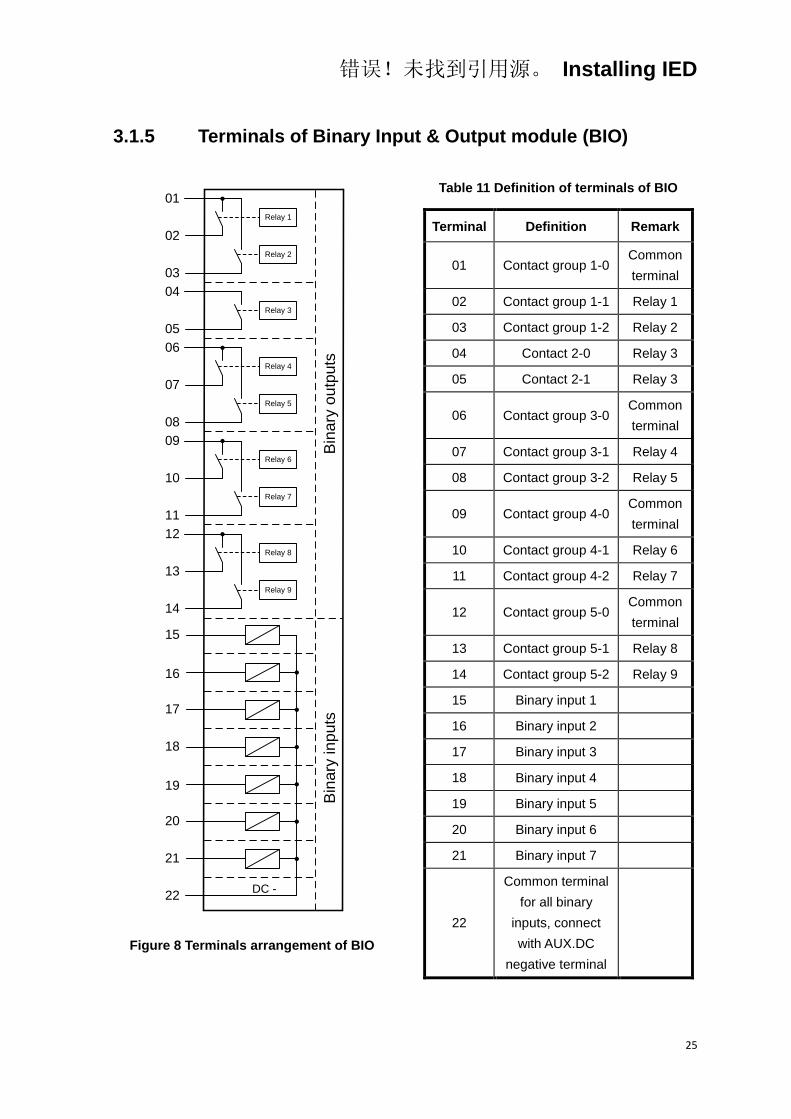
3.1.5 Terminals of Binary Input & Output module (BIO)
08
09
10
11
12
13
14
15
16
17
18
19
Relay 1
Relay 2
Relay 3
Relay 4
Relay 5
Relay 6
Relay 7
Relay 8
Relay 9
01
02
03
05
04
DC -
06
07
20
21
22
Bin
ary
ou
tpu
tsB
ina
ry in
pu
ts
Figure 8 Terminals arrangement of BIO
Table 11 Definition of terminals of BIO
Terminal Definition Remark
01 Contact group 1-0 Common
terminal
02 Contact group 1-1 Relay 1
03 Contact group 1-2 Relay 2
04 Contact 2-0 Relay 3
05 Contact 2-1 Relay 3
06 Contact group 3-0 Common
terminal
07 Contact group 3-1 Relay 4
08 Contact group 3-2 Relay 5
09 Contact group 4-0 Common
terminal
10 Contact group 4-1 Relay 6
11 Contact group 4-2 Relay 7
12 Contact group 5-0 Common
terminal
13 Contact group 5-1 Relay 8
14 Contact group 5-2 Relay 9
15 Binary input 1
16 Binary input 2
17 Binary input 3
18 Binary input 4
19 Binary input 5
20 Binary input 6
21 Binary input 7
22
Common terminal
for all binary
inputs, connect
with AUX.DC
negative terminal
错误!未找到引用源。 Installing IED
26
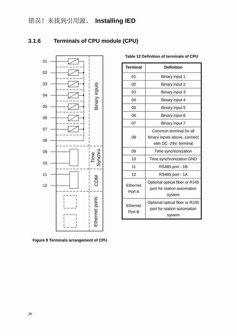
3.1.6 Terminals of CPU module (CPU)
Eth
ern
et p
ort
sC
OM
Tim
e
Syn
ch
roB
ina
ry in
pu
ts
01
02
03
05
06
07
08
09
10
04
11
12
Figure 9 Terminals arrangement of CPU
Table 12 Definition of terminals of CPU
Terminal Definition
01 Binary input 1
02 Binary input 2
03 Binary input 3
04 Binary input 4
05 Binary input 5
06 Binary input 6
07 Binary input 7
08
Common terminal for all
binary inputs above, connect
with DC -24V. terminal
09 Time synchronization
10 Time synchronization GND
11 RS485 port - 1B
12 RS485 port - 1A
Ethernet
Port A
Optional optical fiber or RJ45
port for station automation
system
Ethernet
Port B
Optional optical fiber or RJ45
port for station automation
system
错误!未找到引用源。 Installing IED
27
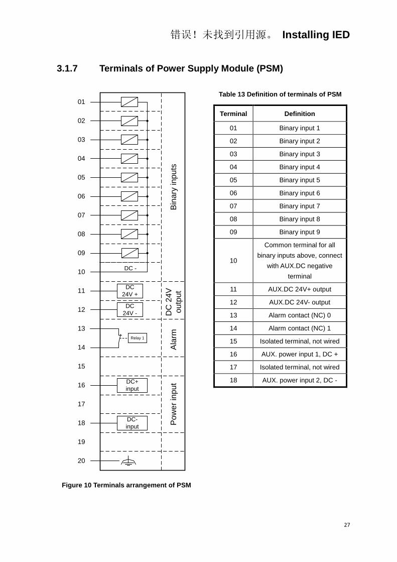
3.1.7 Terminals of Power Supply Module (PSM)
01
02
03
05
06
07
08
09
10
11
12
04
13
14
15
16
17
18
19
20
DC
24V +
DC
24V -
DC+
input
DC -
Relay 1
Bin
ary
in
pu
tsD
C 2
4V
ou
tpu
tA
larm
Po
we
r in
pu
t
DC-
input
Figure 10 Terminals arrangement of PSM
Table 13 Definition of terminals of PSM
Terminal Definition
01 Binary input 1
02 Binary input 2
03 Binary input 3
04 Binary input 4
05 Binary input 5
06 Binary input 6
07 Binary input 7
08 Binary input 8
09 Binary input 9
10
Common terminal for all
binary inputs above, connect
with AUX.DC negative
terminal
11 AUX.DC 24V+ output
12 AUX.DC 24V- output
13 Alarm contact (NC) 0
14 Alarm contact (NC) 1
15 Isolated terminal, not wired
16 AUX. power input 1, DC +
17 Isolated terminal, not wired
18 AUX. power input 2, DC -

错误!未找到引用源。 Installing IED
28
3.1.8 RS232 port
RS232 serial port is located on front panel, the software tool in PC can be
connected with the IED via this port to make setting, testing and cofiguration,
etc.
3.2 Connecting to protective earth
Connect the earthing screw on the rear panel to the nearest protective
earthing point in the cubicle. The protective earth cables should be green or
yellow conductors with cross-sectional area 2.5mm2 according to electrical
regulations and electrical standards requirement.
The cubicle must be properly connected to station earthing system, using the
conductor with cross-sectional area of at least 4mm2.
3.3 Connecting the power supply module
The wiring from the cubicle terminal block to the IED terminals must be
connected in accordance with the established guidelines for this type of IED.
The wires from binary inputs and outputs and the auxiliary power supply must
be routed separated from the current transformer cables between the terminal
blocks of the cubicle and the IEDs connections.
3.4 Connecting to CT and VT circuits
CT and VT are connected to the analogue input module on the rear side of
the IED.
Using solid conductor with cross-sectional 2.5-6mm2 (AWG14-10) or stranded
conductor with cross-sectional 2.5-4mm2 (AWG14-12). The screws used for
fixation conductor should be tightened.
3.5 Connecting the binary inputs and outputs
Auxiliary power supply and binary input and output signals are connected
using female connectors. Signal wires are connected to a female connector,
which is then plugged into the corresponding male connector, located at the

错误!未找到引用源。 Installing IED
29
rear of the IED.
Procedure:
1. Connect signals to the female connector
All wiring to the female connector should be done before it is plugged into
the male part and screwed to the case. The conductors can be of rigid
type (solid, stranded) or of flexible type.
The female connectors accept conductors with a cross section area of
0.2-1.5 mm2 (AWG 24-15). If two conductors are used in the same
terminal, the maximum permissible cross section area is 0.2-0.8 mm2
(AWG 24-18, each conductor corresponding to one cross section area).
If two conductors, each with area 1.5 mm2 (AWG 15) need to be
connected to the same terminal, a ferrule must be used to combine the
two conductors, no soldering is needed. Wires with a smaller gauge can
be inserted directly into the female connector receptacle and the
fastening screw shall be tightened.
2. Plug the connector to the corresponding back-side mounted male
connector
3. Lock the connector by fastening the lock screws
3.6 Making the screen connection
When using screened cables always make sure screens are earthed and
connected according to applicable engineering methods. This may include
checking for appropriate earth points near the IED, for instance, in the cubicle
and/or near the source of measuring. Ensure that earth connections are
made with short conductors of an adequate cross section, at least 6 mm2
(AWG10) for single screen connections.
3.7 RS485 and RS232 ports connection
3.7.1 RS485 port connection
The RS485 interface is capable of half-duplex service with the signals A/A'
and B/B' to transmit signals.
错误!未找到引用源。 Installing IED
30
The network topology of RS485 adopts bus type of terminal matched, do not
support ring or star network. Use the single and continuous channel as bus.
The terminating resistance is located on beginning and terminal of the bus
cable. The other ports do not need the terminating resistance.
As shown in Figure 9, RS485 port located on the rear side of communication
module. The IED provides two electrical isolation RS485 ports, the two ports
can work at the same time with IEC60870-5-103 protocol supported.
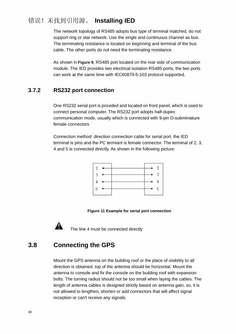
3.7.2 RS232 port connection
One RS232 serial port is provided and located on front panel, which is used to
connect personal computer. The RS232 port adopts half-dupex
communication mode, usually which is connected with 9-pin D-subminiature
female connectors
Connection method: direction connection cable for serial port, the IED
terminal is pins and the PC termianl is female connector. The terminal of 2, 3,
4 and 5 is connected directly. As shown in the following picture:
Figure 11 Example for serial port connection
The line 4 must be connected directly
3.8 Connecting the GPS
Mount the GPS antenna on the building roof or the place of visibility to all
direction is obtained, top of the antenna should be horizontal. Mount the
antenna to console and fix the console on the building roof with expansion
bolts. The turning radius should not be too small when laying the cables. The
length of antenna cables is designed strictly based on antenna gain, so, it is
not allowed to lengthen, shorten or add connectors that will affect signal
reception or can't receive any signals.

错误!未找到引用源。 Installing IED
31
The principle for mounting GPS antenna is that the position is visible
completely to all directions in 360°, however, for some special conditions,
mount the antenna at the place with best visibility as far as possible.
The GPS port is located on the rear side of communication module, as shown
in Figure 9, which can be connected with screened twist-pair cable.

错误!未找到引用源。 Installing IED
32
4 Checking before energizing
4.1 Introduction
After completing the IED connections, the related connections need to be
checked, this section descirbes what should be checked before energizing.
This is done with IED and all connected circuits de-energized.
4.2 Checking the protective earth connection
Check the protective earthing connection of IED is connected reliably in
accordance with the related electrical regulations and standards.
4.3 Checking the power supply connection
Check that the auxiliary power supply voltage remains within the permissible
input voltage range under all operating conditions. Check that the polarity is
correct.
4.4 Checking the CT and VT circuits connection
4.4.1 Checking the CT circuits connection
Check that the wiring is in strict accordance with the supplied connection
diagram. If any errors appearance, do not continue before any errors are
corrected. The following tests shall be performed on every primary CT
connected to IED:
Primary injection test to verify the current change ratio of the CT, the
correct wiring up to the protection IED and correct phase sequence
connection (i.e. A, B, C)
Polarity checking to prove that the predicted direction of secondary
current flow is correct for a given direction of primary current flow
CT secondary loop resistance measurement in order to confirm that the
current transformer secondary loop DC resistance is within specification
and that there are no high resistance joints in the CT winding or wiring
错误!未找到引用源。 Installing IED
33
CT excitation test in order to confirm that the current transformer is of the
correct accuracy rating and that there are no shorted turns in the current
transformer windings. Manufacturer's design curves should be available
for the current transformer in order to compare the actual results
Check the earthing of the individual CT secondary circuits to verify that
each three-phase set of main CTs is properly connected to the station
earth and only at one electrical point
Checking the insulation resistance
Phase identification of CT shall be made
Both primary and secondary sides must be disconnected from the
line and IED when plotting the excitation characteristics
If the CT secondary circuit earth connection is removed without the
current transformer primary being de-energized, dangerous voltages
may result in the secondary CT circuits
4.4.2 Checking the VT connection
Check that the wiring is in strict accordance with the supplied connection
diagram. If any errors appearance, do not continue before any errors are
corrected.
The following tests are recommended:
Polarity check
VT circuit voltage measurement (primary injection test)
Grounding check
Phase relationship
Insulation resistance check
4.5 Checking the binary input and output connection
4.5.1 Checking the binary input connection

错误!未找到引用源。 Installing IED
34
When checking the binary inputs, it's better to disconnect the binary input
connector from binary input module. Check all connected signals in order to
make sure that both the input level and polarity of voltage are in accordance
with the IEDs specifications.
4.5.2 Checking the binary output connection
When checking the binary outputs, it's better to disconnect the binary output
connector from binary output module. Check all connected signals in order to
make sure that both the input level and polarity of voltage are in accordance
with the IEDs specifications.
4.6 Checking the screened cables connection
Check that the screened cables are connected correctly.
4.7 Checking the S485 and RS232 port connectios
4.7.1 Checking the RS485 port connection
Check that the RS485 port connections are correct.
4.7.2 Checking RS232 port connection
Check that the RS232 serial port connections are correct.
4.8 Checking GPS connection
Check that the GPS connections are correct.
4.9 Checking the insulation voltage and insulation
resistance
4.9.1 Checking the insulation voltage

错误!未找到引用源。 Installing IED
35
Using the withstand voltage tester to apply correspondung level voltage
between tested circuit and earth, and between circuits (e.g. 2000VAC
/2800VDC), lasting 1 min. No flashover and breakdown apperance, the
leakage current is less than 10mA.
4.9.2 Checking the insulation resistance
Using a rotating meter with 500V to test insulation resistance in turn between
analog circuits and earth, and the circuits to each other. Every resistance
must not be less than 100 MΩ. And the lasting time for resistance test is not
less than 5s to ensure that the value of insulation resistance is read in a
steady state.
错误!未找到引用源。 Installing IED
36
5 Checking after energizing
5.1 Introduction
After completing of the external circuits connection, checking all connections
and energizing the IED, LCD and keyboard should be tested. Check that the
software version, serial number and the installed modules are in accordance
with ordering information. The IED time need to be set to ensure that the IED
time is synchronized with local time. The self-supervision function should also
be checked to verify that the IED operates properly.
5.2 Test LCD
After energizing the IED, the blue back light of LCD light up, operate the keys
to turn pages to check that the LCD display is correct.
5.3 Test the keyboard
All the keys on front panel including Arrow keys, Reset key, Set key and Quit
key can be operated to check that these keys satisfy with the correpsonding
function, the detail functions of each key are described in Table 2.
5.4 Setting the IED time
This procedure describes how to set the IED time from the local HMI.
1. Enter into the time setting menu: OpConfig/Time, press the Set button to
enter into the setting menu
2. Set the date and time
Use the Left and Right arrow buttons to move between the time and date
values (year, month, day, hours, minutes and seconds). Use the Up and
Down arrow buttons to change the value.
3. Confirm the setting
Press the Set button to set the data and clock to the new values.

错误!未找到引用源。 Installing IED
37
5.5 Checking the software and hardware version
Enter into menu: DevInfo/Version
Checking the software version: In this menu, to check the protection
programm and protection scheme and HMI program version.
Check the hardware version: In this menu, to check the equipment code.

错误!未找到引用源。 Installing IED
38

错误!未找到引用源。 Read and change setting
39
Chapter 4 Read and change setting
About this chapter
This chapter describes how to set and read the setting values
and parameters either through LHMI or software tool, and how
to switch the setting value group.
This chapter does not contain instructions on how to calculate
the setting value, for the detail setting calculation information
please refer to the Technical application manual.

错误!未找到引用源。 Read and change setting
40
1 Read and change the setting vaule
1.1 Read and change the setting value via LHMI
1.1.1 Introduction
All the function settings, binary settings and connectors can be read and set
through LHMI. The user can browse to the desired settings and enter into the
appropriate vaules. The parameters for each function can be found in the
LHMI. See the Technical applciation manual for a complete list of setting
parameters for each function.
1.1.2 Communication parameter
1.1.2.1 Ethernet address
Enter into menu: ComConf/Eth 1#
Enter into menu: ComConf/Eth 2#
The address of Ethernet port 1and Ethernet 2 can be modified in this setting.
1.1.2.2 BIO parameter
Enter into menu: ComConf/Monitor
The related parameter about BIO module can be modified in this setting.
1.1.2.3 Serial port parameter
Enter into menu: ComConf/Serial
In this menu, the parameter for RS232 and RS485 port can be set, such as
baud rate, transmission protocol, etc.
1.1.2.4 Label parameter
Enter into menu: ComConf/Label
In this menu, the LON address, STA name and Bay name can be set.
错误!未找到引用源。 Read and change setting
41
1.1.2.5 Time synchronization mode
Network mode
Enter into menu: DevSetup/Remote/Signal/SynType
The time synchronization mode can be changed into network time mode via
this setting.
IRIG-B Mode
Enter into menu: DevSetup/Remote/Signal/SynType
The time synchronization mode can be changed into IRIG-B time mode via
this setting.
1.1.3 Setting values, binary settings and soft connetors for
protection function
1.1.3.1 Protection setting
Enter into menu: Settings/Write/Select
The menu of protection setting is used to check and modify every function
setting, using left and right button to chose the vaule and the up and down
buttons are used to modify the value, the upper and lower limits of setting
value will be displayed when the cursor move to corresponding setting items.
1.1.3.2 Protection binary setting
Enter into menu: Settings/Write/Select
The protection binary settings are used to enable or disable each function.
Two ways for modifying the binary setting via LHMI:
1. Modify the value of hex format displayed in this menu to enable or disable
the corresponding function.
2. Press the right button for a while, the detail information for this binary
setting will be displayed, using up and down button to select the required
function and the left and right button to enable or disable this function.

错误!未找到引用源。 Read and change setting
42
1.1.3.3 Protection soft connector
Enter into menu: OpConfig/Connect
The protection soft connectors are used to enable or disable each function,
On means enable and Off means disable. Use the up and down button to
select the required connector and the left and right button to enable or disable
this function.
错误!未找到引用源。 Read and change setting
43
2 Switching the setting group
2.1 Introduction
There are 16 setting groups with same setting items in the IED, for each
group settings can be set and saved separately, the different setting groups
can be switched according to different application.
2.2 Method for switching setting group via LHMI
Enter into the menu: Settings/Switch
Enter into the menu: Opconfig/Switch
The current setting group number and the chosen setting group number are
displayed in the LCD, change the setting group number by up and down
button, comfirm the result by Set button after the setting group number is
chosen.
After setting group switching success, the information about switching
success will be reported.
Note: the functions are related with setting value, binary setting as well as
connector, so, the group number for setting value and connector should be
consistent in order to make sure the IED operate normally.
2.3 Method for switching setting group via binary
input
Enter into the menu: Settings/Switch
The binary setting "BI SetGrp Switch" in the menu described above is used
for switching setting group via binary input, when this binary setting is set to 1,
and the corresponding binary input is active, the setting group is switched
from group 1 to group 2. If the binary setting is set to 1 and the binary input is
inactive, the setting group is switched from group 2 to group 1.
Note: The method for swithing setting group via binary input is only available
for switching between group 1 and group2.

错误!未找到引用源。 Read and change setting
44
错误!未找到引用源。 Testing the communication
connection and time synchronization
45
Chapter 5 Testing the communication
connection and time
synchronization
About this chapter
This chapter describes how to test each communication port and
the function of time synchronization.
错误!未找到引用源。 Testing the communication connection and time synchronization
46
1 Testing the communication connection
1.1 Testing the Ethernet communication
1.1.1 Testing the electrical Ethernet communication
Connect the IED with automation system to check the connection is
successful, if connection fail, check the communication network.
If connection successes, in the menu: Testing/Remote/Signal, send the
simulation point information to automation system, check the information and
compare with IED information, if the automation system does not receive any
information or the information received is not true, check the automation
system configuration.
1.1.2 Testing the optical Ethernet communication
Connect the IED with automation system to check the connection is
successful, if connection fail, check the communication network.
If connection successes, in the menu: Testing/Remote/Signal, send the
simulation point information to automation system, check the information and
compare with IED information, if the automation system does not receive any
information or the information received is not true, check the automation
system configuration.
1.2 Testing the RS485 port
Connect the IED with automation system to check the connection is
successful, if connection fail, check the communication network.
If connection successes, in the menu: Testing/Remote/Signal, send the
simulation point information to automation system, check the information and
compare with IED information, if the automation system does not receive any
information or the information received is not true, check the automation
system configuration.
1.3 Testing the RS232 port

错误!未找到引用源。 Testing the communication
connection and time synchronization
47
Using the dedicated cable for serial port to connect the PC with IED, if
connection fail, check the corresponding configuration of IED is true or not. If
all configurations are true, and the connection is still unsuccessful, please
check the connection cable and communication port.

错误!未找到引用源。 Testing the communication connection and time synchronization
48
2 Testing the time synchronization
2.1 Network mode
Select time synchronization mode:
DevSetup/Remote/Signal/SynType
Change the IED time to any other time
Wait for a period of time
Check that the IED time is changed automatically in accordance with time
synchronization source
2.2 IRIG-B mode
Select time synchronization mode:
DevSetup/Remote/Signal/SynType
Change the IED time to any other time
Wait for a period of time
Check that the IED time is changed automatically in accordance with time
synchronization source

错误!未找到引用源。 IED testing
49
Chapter 6 IED testing
About this chapter
This chapter describes the method of hardware testing, such as
power supply, binary input and output, analog quantities and all
functions testing method and testing procedure.

错误!未找到引用源。 IED testing
50
1 Introduction
IED test requirements:
Setting value list
The IED setting value must be completed before the testing can start.
Application configuration diagram
Terminal diagram
The terminal diagram and module arrangement diagram, available in the
Technical reference manual, is a general diagram of the IED. but note
that the same diagram is not always applicable to each specific delivery
(especially for the configuration of all the binary inputs and outputs).
Therefore, before testing, check that the available terminal diagram
corresponds to the IED.
Technical application maunal
The Technical application manual contains application and functionality
summaries, function block, logic diagram, input and output signals,
setting parameters and technical data sorted per function.
The three-phase test equipment
The test equipment should be able to provide a three-phase supply of
voltages and currents. The magnitude of voltage and current as well as
the phase angle between voltage and current must be variable. The
voltages and currents from the test equipment must be obtained from the
same source and they must have minimal harmonic content. If the test
equipment cannot indicate the phase angle, a separate phase-angle
measuring instrument is necessary.
Prepare the IED for test before testing a function. Consider the logic diagram
of the tested protection function when perform the test. All included functions
in the IED are tested according to the corresponding test instrunctions in this
chapter.
The response from a test can be viewed in different ways:
Binary output signals

错误!未找到引用源。 IED testing
51
Display value in HMI
All setting groups that are used should be tested.
The IED is designed for a maximum continuous current of three
times the rated current
Please observe the measuring accuracy of the IED, the test
equipment and angular accuracy for both of them

错误!未找到引用源。 IED testing
52
2 Points for attention during testing
Be familiar with the engineering drawings, engineering and operation
manual and technical application manual
Before testing, check that the short-circuited wire used to avoid CT
secondary circuit opening is connected correctly and firmly. The
short-circuited phenomenon of VT secondary circuit does not exist
It is allowed to plug-in and pull out each module after the power supply
disconnection. Aviod AC current circuit opened when plug in and pull out
the modules
Keep cleaning and pay attention to dust prevention for each module
Adoption the measure of the human body electrostatic grounding
prevention to make sure that the IED is not damaged by hunam
electrostatic
In principle, the electric iron can't be used in field, if the electric iron need
to be used for welding during testing, the welding can be performed after
the power disconnection or using the electric iron with earthed wire
During testing, do not insert the module into the wrong position. When
plug in and pull out the module apply appropriate force instead of
overexerting to avoid pins bending or damage the fastening components
of module
Short-circuited or disconnected terminals temporarily for checking, it
should be recorded one by one and return to original state after the
testing is completed
Using the electronic devices (e.g. oscillograph, etc.) with AC power
supply to measure the circuit parameters, the case of the device should
be earthed in the same grounding with protection IED cabinet
During testing, consider the safety measure between the IED and other
running equipment and the safety measure of related circuit between
external running equipment and the IED
During testing, if the current magnitude that is input into IED is large than
three times of rated current, it should be noticed that the time should not
be too long

错误!未找到引用源。 IED testing
53
When energizing the IED in the first time, using multimeter to check the
power supply, the circuit of voltages and currents are connected correcly
to avoid short circuit or open circuit
Tighten all the screws of all terminals again for the new project in order to
prevent improper connection, and plug in and pull out all the modules
again to aovid the modules loosing result from operation or installation

错误!未找到引用源。 IED testing
54
3 Preparing for test
3.1 Introduction
Please read the corresponding manuals that is provided by manufacturer
in detail before testing, try best to understand the basic operation,
protection principle and the relevant capabilities. If have any questions in
this procedure, please inquire the field service engineer or the technical
support engineer of SiFang.
All checking should be done before energizing, inspection well and no
damage on the surface, all modules are inserted firmly, the insulation of
the power circuit are satisfied the specified requirement.
Disconnect the external circuit before testing to avoid safety accident or
injuries to the human
If the modules are needed to be plugged in or pulled out, make sure that
the power is disconnected, and the measure of prevention electrostatic
should be done in order to avoid the damage to module or performance
degradation
The opened or short-circuited terminal temporarily should be recorded in
detail in order to return to original state reliably
3.2 Connecting test equipment to IED
Before testing, connect the test equipment according to the IED specific
connection diagram. Pay special attention to the correct connection of the
input and output current terminals. Check that the input and output logical
signals in the logic diagram for the function under test are connected to the
corresponding binary inputs and outputs of the IED. The testing connection
diagram is shown in Figure 12.
The user must verify that the connections are correct and the analog signals
are measured correctly after connection completed.
Procedure:
1. Inject a symmetrical three-phase current and voltage at rated value
2. Inject a phase-to-phase voltage and phase-to-phase current at rated
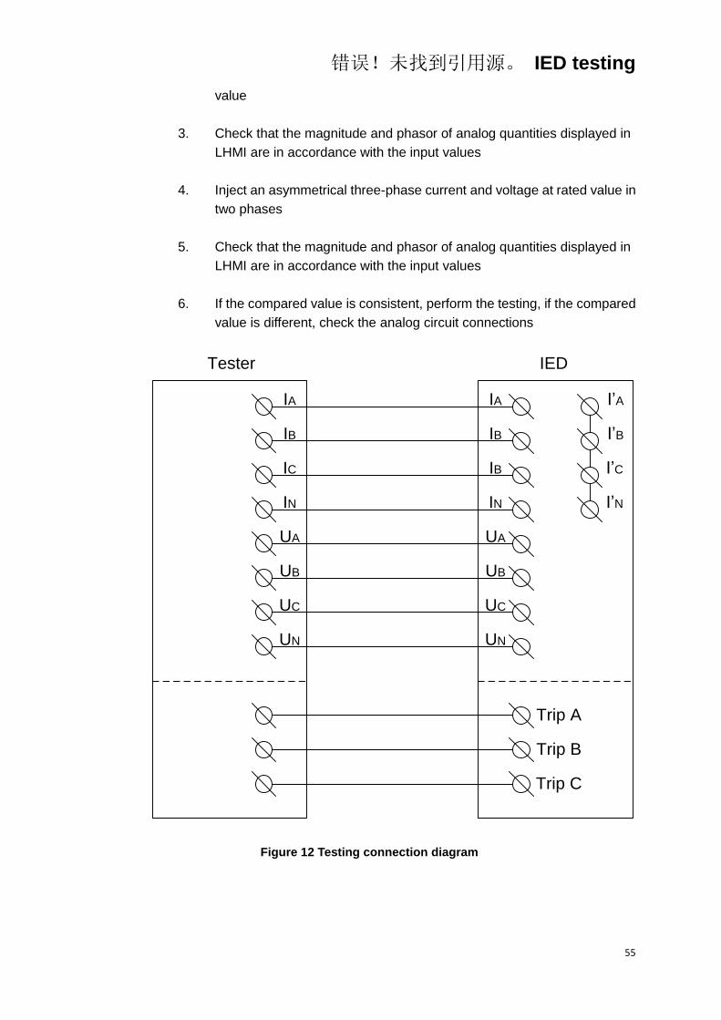
错误!未找到引用源。 IED testing
55
value
3. Check that the magnitude and phasor of analog quantities displayed in
LHMI are in accordance with the input values
4. Inject an asymmetrical three-phase current and voltage at rated value in
two phases
5. Check that the magnitude and phasor of analog quantities displayed in
LHMI are in accordance with the input values
6. If the compared value is consistent, perform the testing, if the compared
value is different, check the analog circuit connections
IA
IB
IC
IN
UA
UB
UC
UN
IA
IB
IB
IN
UA
UB
UC
UN
I’A
I’B
I’C
I’N
Trip A
Trip B
Trip C
Tester IED
Figure 12 Testing connection diagram

错误!未找到引用源。 IED testing
56
4 Testing the power supply
4.1 Checking the self-startup performance
Power on the IED, in order to check the self-startup performance of the IED,
energizing the IED with the voltage rised slowly from zero to 80% rated
voltage, at this time, observe the green “Run” LED on the front panel that
should be lighted continuously. After the DC power disappears, the normal
closed contact should be disconnected, which can be tested using the
multimeter, the contact is show in Figure 10.
4.2 DC power on and power off testing
Changing the DC power to 80% rated voltage, power off and power on the
power supply some times, the “Run” LED on the front panel should turn off
and turn on correspondingly. The normal closed contact should be in the “on”
or “off” state. The contact is show in Figure 10.
4.3 Checking the expiry date of power supply
When period checking, check the expiry date of the power supply module, if
the power supply module has been used more than 5 years, please replace it.
错误!未找到引用源。 IED testing
57
5 Checking the analog channel
5.1 Checking and adjusting the zero drift
MainMenu/Testing/Zero
In this menu, the zero drift values of all analog channels have been listed in
detail, check that the zero drift is met the requirement. Generally, the
requirement of the current channels is <0.01In, the voltage channels is <0.5V.
If the zero drift value is not satisfied the requirement, adjust the corresponding
zero drift.
MainMenu/DevSetup/Zero
MainMenu/DevSetup/Save
It is allowed to check zero drift after energizing the IED for 5 minutes, when
adjusting the zero drift, disconnect electrical connection of the IED, test
equipment, standard source and external circuit, make sure that there are no
any inputs to analog terminals, select the menu and adjust zero drift. After
zero drift adjustment succeed, enter into the " Save " menu to complete the
adjustment.
5.2 Checking and calibrating
MainMenu/OpConfig/Analog
MainMenu/OpConfig/Metering
The analog quantities scale for protection function is not used to be adjusted,
the accuracy is guaranteed by hardware. For the scale adjustment, Only the
measurement channel is adjusted.
Before testing, disable all of the connectors and binary settings in order to
avoid the protection function startup or maloperation.
Using the test equipment with 0.1 grade, connect the voltages and currents of
test equipment to the corresponding input terminals to check the magnitude
and phase angle of voltage and current. The magnitude tolerance of IED
displaying value and external injected value should be less than ±2.5%
(phase voltage vaule tolerance <0.2V when voltage channel is 1V, zero
错误!未找到引用源。 IED testing
58
sequence voltage tolerance <0.2V when voltage channel is 3V; current value
tolerance <0.02In when current channel is 0.08 In).
MainMenu/DevSetup/Scale
MainMenu/DevSetup/Save
Make sure that zero adjustment have been completed before scale
adjustment, and then inject rated voltage and current, after the standard
source output steadily, enter into the menu described above to adjust scale.
After scale adjustment succeed, enter into the " Save " menu to complete the
adjustment. And then check the measurement value, the accuracy
requirement is: tolerance of voltage and current should be less than ±0.2%
and tolerance of power should be less than ±0.5%.
Note: during testing, if the measuring tolerance of the analog quantities are
large than the required range, check that the testing connection, testing
method and external measurement meter is correct, the testing source has
not wave distortion, before all of the exteral equipments are checked, it
should not adjust or change the components of the IED immediately.
错误!未找到引用源。 IED testing
59
6 Testing binary input
MainMenu/Testing/BI
Check the binary input status in this menu, all the binary input status should
be displayed as "empty circle" icon. Make sure that the circuit of binary input
is in good condition, the power of binary input have been connected (24V,
110V or 220V). Test the binary input one by one according to the engineering
drawing, the tested binary input status displayed in HMI should be displayed
as "solid circle" icon.

错误!未找到引用源。 IED testing
60
7 Testing binary output
MainMenu/Test BO
Testing binary output in this menu to verify the correctness of signal circuit
and output circuit.
During testing the binary output, the corresponding relay contact operate, the
irrelevant contacts should not operate. Use the multimeter to measure the
corresponding output contacts of the tripping and signal.

错误!未找到引用源。 IED testing
61
8 Verifying the IED functions
Procedure:
1. Enable the protection function binary setting via software tool or LHMI
2. Input the corresponding settings value via software tool or LHMI
3. Input the rated currents and voltages to make the IED operating
normally for 20s
4. Active the binary input for the corresponding protection function
5. Simulate the fault occurance
6. Observe the testing result
7. Stop the output from test equipment and restore to original state
8. Continue to test another function or complete the test
8.1 Overcurrent protection
Before starting the test, please make sure that the protection function setting
values and parameters are correct, refer to section Introduction, Points for
attention during testing and Preparing for test in this chapter.
8.1.1 Verifying the settings
8.1.1.1 Verifying the settings of stage 1 of overcurrent protection
1 Verifying the phase A setting
1.1 Verifying the current setting
Table 14 Current setting verifying
Test item Description
105% of the current setting verifying
Binary setting
OpConfig/Connect/Func_OC1, set the connector as "On"
Settings/Write/Select/Ctr Word 4/OC1 Trip, set the binary setting
as 1
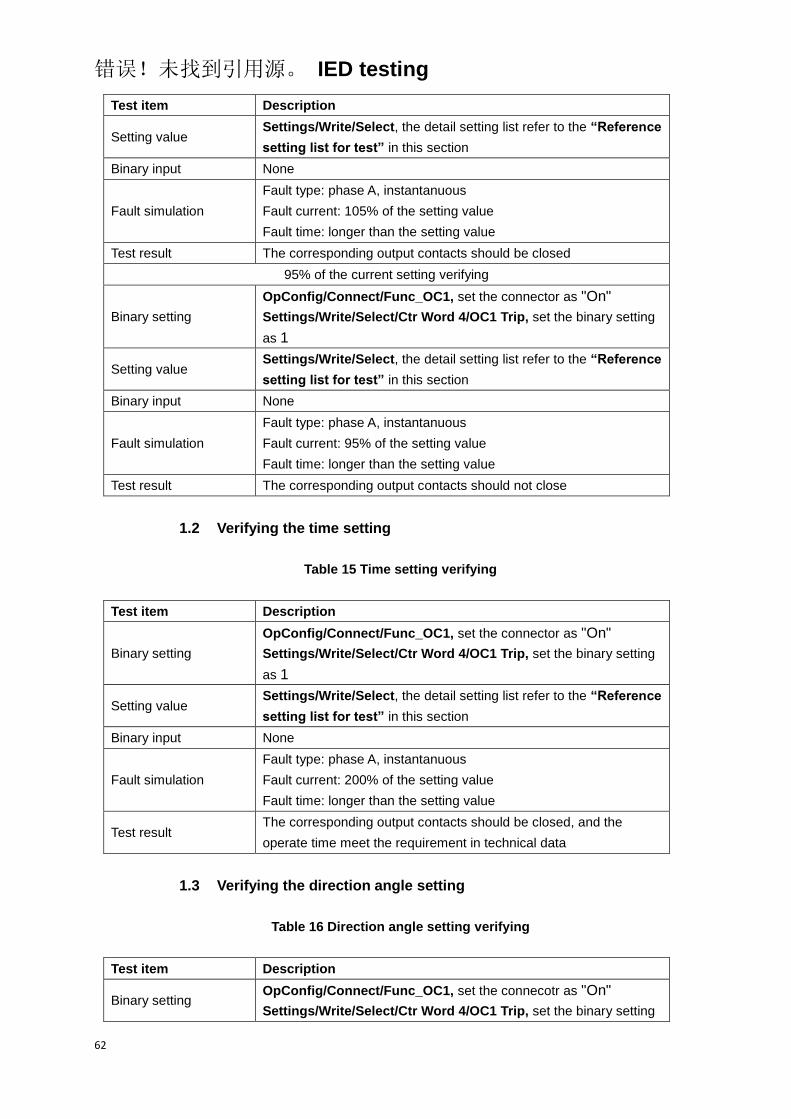
错误!未找到引用源。 IED testing
62
Test item Description
Setting value Settings/Write/Select, the detail setting list refer to the “Reference
setting list for test” in this section
Binary input None
Fault simulation
Fault type: phase A, instantanuous
Fault current: 105% of the setting value
Fault time: longer than the setting value
Test result The corresponding output contacts should be closed
95% of the current setting verifying
Binary setting
OpConfig/Connect/Func_OC1, set the connector as "On"
Settings/Write/Select/Ctr Word 4/OC1 Trip, set the binary setting
as 1
Setting value Settings/Write/Select, the detail setting list refer to the “Reference
setting list for test” in this section
Binary input None
Fault simulation
Fault type: phase A, instantanuous
Fault current: 95% of the setting value
Fault time: longer than the setting value
Test result The corresponding output contacts should not close
1.2 Verifying the time setting
Table 15 Time setting verifying
Test item Description
Binary setting
OpConfig/Connect/Func_OC1, set the connector as "On"
Settings/Write/Select/Ctr Word 4/OC1 Trip, set the binary setting
as 1
Setting value Settings/Write/Select, the detail setting list refer to the “Reference
setting list for test” in this section
Binary input None
Fault simulation
Fault type: phase A, instantanuous
Fault current: 200% of the setting value
Fault time: longer than the setting value
Test result The corresponding output contacts should be closed, and the
operate time meet the requirement in technical data
1.3 Verifying the direction angle setting
Table 16 Direction angle setting verifying
Test item Description
Binary setting OpConfig/Connect/Func_OC1, set the connecotr as "On"
Settings/Write/Select/Ctr Word 4/OC1 Trip, set the binary setting
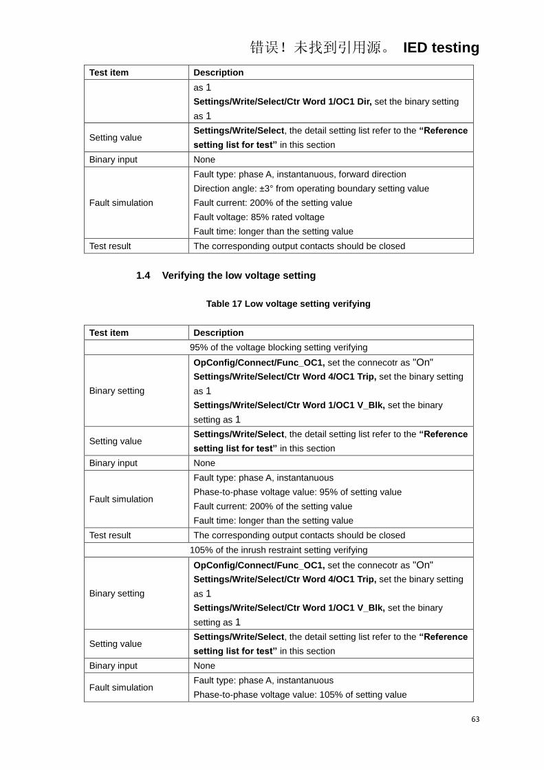
错误!未找到引用源。 IED testing
63
Test item Description
as 1
Settings/Write/Select/Ctr Word 1/OC1 Dir, set the binary setting
as 1
Setting value Settings/Write/Select, the detail setting list refer to the “Reference
setting list for test” in this section
Binary input None
Fault simulation
Fault type: phase A, instantanuous, forward direction
Direction angle: ±3° from operating boundary setting value
Fault current: 200% of the setting value
Fault voltage: 85% rated voltage
Fault time: longer than the setting value
Test result The corresponding output contacts should be closed
1.4 Verifying the low voltage setting
Table 17 Low voltage setting verifying
Test item Description
95% of the voltage blocking setting verifying
Binary setting
OpConfig/Connect/Func_OC1, set the connecotr as "On"
Settings/Write/Select/Ctr Word 4/OC1 Trip, set the binary setting
as 1
Settings/Write/Select/Ctr Word 1/OC1 V_Blk, set the binary
setting as 1
Setting value Settings/Write/Select, the detail setting list refer to the “Reference
setting list for test” in this section
Binary input None
Fault simulation
Fault type: phase A, instantanuous
Phase-to-phase voltage value: 95% of setting value
Fault current: 200% of the setting value
Fault time: longer than the setting value
Test result The corresponding output contacts should be closed
105% of the inrush restraint setting verifying
Binary setting
OpConfig/Connect/Func_OC1, set the connecotr as "On"
Settings/Write/Select/Ctr Word 4/OC1 Trip, set the binary setting
as 1
Settings/Write/Select/Ctr Word 1/OC1 V_Blk, set the binary
setting as 1
Setting value Settings/Write/Select, the detail setting list refer to the “Reference
setting list for test” in this section
Binary input None
Fault simulation Fault type: phase A, instantanuous
Phase-to-phase voltage value: 105% of setting value
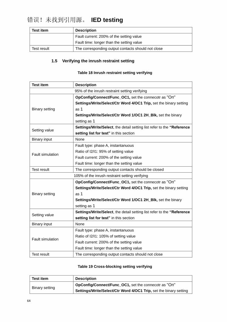
错误!未找到引用源。 IED testing
64
Test item Description
Fault current: 200% of the setting value
Fault time: longer than the setting value
Test result The corresponding output contacts should not close
1.5 Verifying the inrush restraint setting
Table 18 Inrush restraint setting verifying
Test item Description
95% of the inrush restraint setting verifying
Binary setting
OpConfig/Connect/Func_OC1, set the connecotr as "On"
Settings/Write/Select/Ctr Word 4/OC1 Trip, set the binary setting
as 1
Settings/Write/Select/Ctr Word 1/OC1 2H_Blk, set the binary
setting as 1
Setting value Settings/Write/Select, the detail setting list refer to the “Reference
setting list for test” in this section
Binary input None
Fault simulation
Fault type: phase A, instantanuous
Ratio of I2/I1: 95% of setting value
Fault current: 200% of the setting value
Fault time: longer than the setting value
Test result The corresponding output contacts should be closed
105% of the inrush restraint setting verifying
Binary setting
OpConfig/Connect/Func_OC1, set the connecotr as "On"
Settings/Write/Select/Ctr Word 4/OC1 Trip, set the binary setting
as 1
Settings/Write/Select/Ctr Word 1/OC1 2H_Blk, set the binary
setting as 1
Setting value Settings/Write/Select, the detail setting list refer to the “Reference
setting list for test” in this section
Binary input None
Fault simulation
Fault type: phase A, instantanuous
Ratio of I2/I1: 105% of setting value
Fault current: 200% of the setting value
Fault time: longer than the setting value
Test result The corresponding output contacts should not close
Table 19 Cross-blocking setting verifying
Test item Description
Binary setting OpConfig/Connect/Func_OC1, set the connecotr as "On"
Settings/Write/Select/Ctr Word 4/OC1 Trip, set the binary setting

错误!未找到引用源。 IED testing
65
Test item Description
as 1
Settings/Write/Select/Ctr Word 1/OC1 2H_Blk, set the binary
setting as 1
Setting value Settings/Write/Select, the detail setting list refer to the “Reference
setting list for test” in this section
Binary input None
Fault simulation
Fault type: phase A, instantanuous
Harmonic phase: phase B or phase C
Ratio of I2/I1: 200% of the setting value
Fault current: 200% of the setting value
Cross-blocking time: the same as setting value
Fault time: longer than (cross-blocking time + operate setting value)
Test result
The corresponding output contacts should be closed, the operate
time meet the requirement of technical data (cross-blocking time +
operate time)
Table 20 The maximum inrush current setting verifying
Test item Description
95% of the maximum inrush current restraint setting verifying
Binary setting
OpConfig/Connect/Func_OC1, set the connecotr as "On"
Settings/Write/Select/Ctr Word 4/OC1 Trip, set the binary setting
as 1
Settings/Write/Select/Ctr Word 1/OC1 2H_Blk, set the binary
setting as 1
Setting value Settings/Write/Select, the detail setting list refer to the “Reference
setting list for test” in this section
Binary input None
Fault simulation
Fault type: phase A, instantanuous
Ratio of I2/I1: 200% of the setting value
Fault current: 95% of the maximum inrush current restraint setting
Fault time: longer than the setting value
Test result The corresponding output contacts should not close
105% of the maximum inrush current restraint setting verifying
Binary setting
OpConfig/Connect/Func_OC1, set the connecotr as "On"
Settings/Write/Select/Ctr Word 4/OC1 Trip, set the binary setting
as 1
Settings/Write/Select/Ctr Word 1/OC1 2H_Blk, set the binary
setting as 1
Setting value Settings/Write/Select, the detail setting list refer to the “Reference
setting list for test” in this section
Binary input None
Fault simulation Fault type: phase A, instantanuous
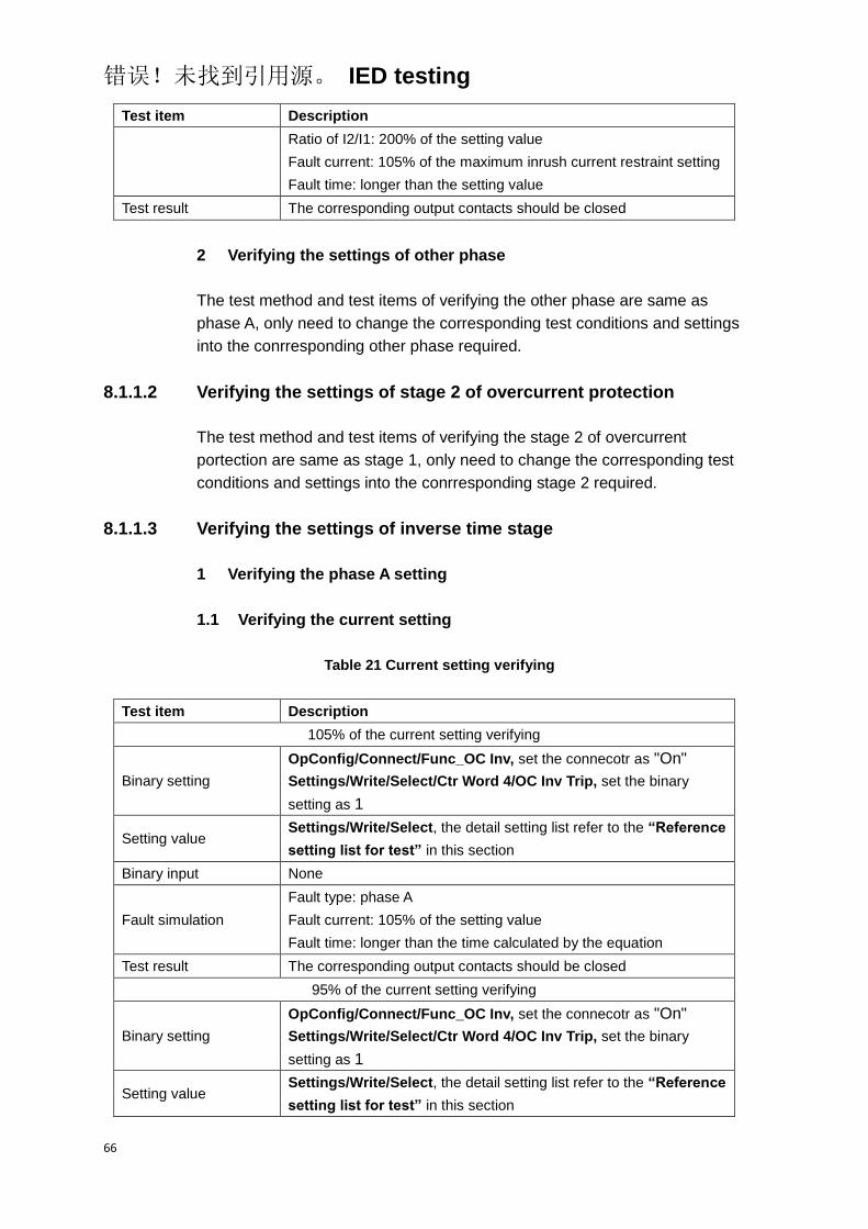
错误!未找到引用源。 IED testing
66
Test item Description
Ratio of I2/I1: 200% of the setting value
Fault current: 105% of the maximum inrush current restraint setting
Fault time: longer than the setting value
Test result The corresponding output contacts should be closed
2 Verifying the settings of other phase
The test method and test items of verifying the other phase are same as
phase A, only need to change the corresponding test conditions and settings
into the conrresponding other phase required.
8.1.1.2 Verifying the settings of stage 2 of overcurrent protection
The test method and test items of verifying the stage 2 of overcurrent
portection are same as stage 1, only need to change the corresponding test
conditions and settings into the conrresponding stage 2 required.
8.1.1.3 Verifying the settings of inverse time stage
1 Verifying the phase A setting
1.1 Verifying the current setting
Table 21 Current setting verifying
Test item Description
105% of the current setting verifying
Binary setting
OpConfig/Connect/Func_OC Inv, set the connecotr as "On"
Settings/Write/Select/Ctr Word 4/OC Inv Trip, set the binary
setting as 1
Setting value Settings/Write/Select, the detail setting list refer to the “Reference
setting list for test” in this section
Binary input None
Fault simulation
Fault type: phase A
Fault current: 105% of the setting value
Fault time: longer than the time calculated by the equation
Test result The corresponding output contacts should be closed
95% of the current setting verifying
Binary setting
OpConfig/Connect/Func_OC Inv, set the connecotr as "On"
Settings/Write/Select/Ctr Word 4/OC Inv Trip, set the binary
setting as 1
Setting value Settings/Write/Select, the detail setting list refer to the “Reference
setting list for test” in this section

错误!未找到引用源。 IED testing
67
Test item Description
Binary input None
Fault simulation
Fault type: phase A
Fault current: 95% of the setting value
Fault time: longer than the time calculated by the equation
Test result The corresponding output contacts should not close
1.2 Verifying the time setting
Table 22 Time setting verifying
Test item Description
Binary setting
OpConfig/Connect/Func_OC Inv, set the connecotr as "On"
Settings/Write/Select/Ctr Word 4/OC Inv Trip, set the binary
setting as 1
Setting value Settings/Write/Select, the detail setting list refer to the “Reference
setting list for test” in this section
Binary input None
Fault simulation
Fault type: phase A
Fault current: 200% of the setting value
Fault time: longer than the time calculated by the equation
Test result
The corresponding output contacts should be closed, the operate
time meet the requirement of calculated by inverse time stage
equation of technical data
Table 23 Inverse time stage characteristic
Inverse time stage characteristic
IEC
Normal inverse
Very inverse
Extremely inverse
Long inverse
ANSI
Normal Inverse
Short inverse
Long inverse
Moderately inverse
Very inverse
Extremely inverse
Definite inverse

错误!未找到引用源。 IED testing
68
Inverse time stage characteristic
User-defined characteristic
Time factor of inverse time, A
Delay of inverse time, B
Index of inverse time, P
Set time Multiplier for step n: k
2 Verifying the settings of other phase
The test method and test items of verifying the other phase of inverse time
stage are same as phase A, only need to change the corresponding test
conditions and settings into the conrresponding other phase required.
8.1.2 Completing the test
Continue to test another function or end the test. Restore connections and
settings to their original values, if they were changed for testing purposes.
8.1.3 Reference setting list for test
Table 24 Overcurrent protection connector list
NO. Default Abbr. Explanation
1. On Func_OC1 Enable or disable the stage 1 of overcurrent protection
2. On Func_OC2 Enable or disable the stage 2 of overcurrent protection
3. On Func_OC Inv Enable or disable the inverse time stage of overcurrent
protection
Table 25 Overcurrent protection function setting list
NO. Default Abbr. Explanation Unit Min. Max.
1. In I_OC1 Current setting for stage 1 A 0.05In 20.00In
2. 0.4 T_OC1 Time setting for stage 1 S 0.00 60.00
3. 1.5In I_OC2 Current setting for stage 2 A 0.05In 20.00In
4. 0.1 T_OC2 Time setting for stage 2 S 0.00 60.00
5. 90.0 U_OC_UnBlk Low voltage setting for V 1.00 120.0
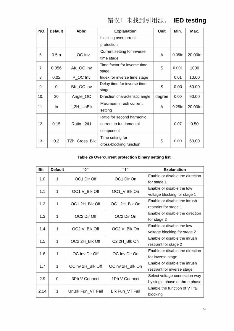
错误!未找到引用源。 IED testing
69
NO. Default Abbr. Explanation Unit Min. Max.
blocking overcurrent
protection
6. 0.5In I_OC Inv Current setting for inverse
time stage A 0.05In 20.00In
7. 0.056 AK_OC Inv Time factor for inverse time
stage S 0.001 1000
8. 0.02 P_OC Inv Index for inverse time stage 0.01 10.00
9. 0 BK_OC Inv Delay time for inverse time
stage S 0.00 60.00
10. 30 Angle_OC Direction characteristic angle degree 0.00 90.00
11. In I_2H_UnBlk Maximum inrush current
setting A 0.25In 20.00In
12. 0.15 Ratio_I2/I1
Ratio for second harmonic
current to fundamental
component
0.07 0.50
13. 0.2 T2h_Cross_Blk Time setting for
cross-blocking function S 0.00 60.00
Table 26 Overcurrent protection binary setting list
Bit Default “0” “1” Explanation
1.0 1 OC1 Dir Off OC1 Dir On Enable or disable the direction
for stage 1
1.1 1 OC1 V_Blk Off OC1_V Blk On Enable or disable the low
voltage blocking for stage 1
1.2 1 OC1 2H_Blk Off OC1 2H_Blk On Enable or disable the inrush
restraint for stage 1
1.3 1 OC2 Dir Off OC2 Dir On Enable or disable the direction
for stage 2
1.4 1 OC2 V_Blk Off OC2 V_Blk On Enable or disable the low
voltage blocking for stage 2
1.5 1 OC2 2H_Blk Off C2 2H_Blk On Enable or disable the inrush
restraint for stage 2
1.6 1 OC Inv Dir Off OC Inv Dir On Enable or disable the direction
for inverse stage
1.7 1 OCInv 2H_Blk Off OCInv 2H_Blk On Enable or disable the inrush
restraint for inverse stage
2.9 0 3Ph V Connect 1Ph V Connect Select voltage connection way
by single phase or three phase
2.14 1 UnBlk Fun_VT Fail Blk Fun_VT Fail Enable the function of VT fail
blocking

错误!未找到引用源。 IED testing
70
Bit Default “0” “1” Explanation
4.0 1 OC1 Alarm OC1 Trip Stage 1 of overcurrent
protection alarm or trip
4.1 1 OC Inv Alarm OC Inv Trip Inverse stage of overcurrent
protection alarm or trip
8.2 Earth fault protection
Before starting the test, please make sure that the protection function setting
values and parameters are correct, refer to section Introduction, Points for
attention during testing and Preparing for test in this chapter.
8.2.1 Verifying the settings
8.2.1.1 Verifying the settings of stage 1 of earth fault protection
1 Verifying the phase A setting
1.1 Verifying the zero-sequence current setting
Table 27 Zero-sequence current setting verifying
Test item Description
105% of the zero-sequence current setting verifying
Binary setting
OpConfig/Connect/Func_EF1, set the connecotr as "On"
Settings/Write/Select/Ctr Word 4/EF1 Trip, set the binary setting
as 1
Setting value Settings/Write/Select, the detail setting list refer to the “Reference
setting list for test” in this section
Binary input None
Fault simulation
Fault type: phase A, instantanuous
Fault current: 105% of the setting value
Fault time: longer than the setting value
Test result The corresponding output contacts should be closed
95% of the zero-sequence current setting verifying
Binary setting
OpConfig/Connect/Func_EF1, set the connecotr as "On"
Settings/Write/Select/Ctr Word 4/EF1 Trip, set the binary setting
as 1
Setting value Settings/Write/Select, the detail setting list refer to the “Reference
setting list for test” in this section
Binary input None
Fault simulation Fault type: phase A, instantanuous

错误!未找到引用源。 IED testing
71
Test item Description
Fault current: 95% of the setting value
Fault time: longer than the setting value
Test result The corresponding output contacts should not close
1.2 Verifying the time setting
Table 28 Time setting verifying
Test item Description
Binary setting
OpConfig/Connect/Func_EF1, set the connecotr as "On"
Settings/Write/Select/Ctr Word 4/EF1 Trip, set the binary setting
as 1
Setting value Settings/Write/Select, the detail setting list refer to the “Reference
setting list for test” in this section
Binary input None
Fault simulation
Fault type: phase A, instantanuous
Fault current: 200% of the setting value
Fault time: longer than the setting value
Test result The corresponding output contacts should be closed, and the
operate time meet the requirement in technical data
1.3 Verifying the direction angle setting
Table 29 Zero-sequence direction angle setting verifying
Test item Description
Binary setting
OpConfig/Connect/Func_EF1, set the connecotr as "On"
Settings/Write/Select/Ctr Word 4/EF1 Trip, set the binary setting
as 1
Settings/Write/Select/Ctr Word 1/EF1 Dir, set the binary setting as
1
Setting value Settings/Write/Select, the detail setting list refer to the “Reference
setting list for test” in this section
Binary input None
Fault simulation
Fault type: phase A, instantanuous, forward direction
Direction angle: ±3° from operating boundary setting value
Zero sequence current: 200% of the setting value
Zero sequence voltage: 85% rated voltage
Fault time: longer than the setting value
Test result The corresponding output contacts should be closed
Table 30 Negative-sequence direction angle setting verifying

错误!未找到引用源。 IED testing
72
Test item Description
Binary setting
OpConfig/Connect/Func_EF1, set the connecotr as "On"
Settings/Write/Select/Ctr Word 4/EF1 Trip, set the binary setting
as 1
Settings/Write/Select/Ctr Word 1/EF1 Dir, set the binary setting as
1
Settings/Write/Select/Ctr Word 1/EF U2/I2 Dir, set the binary
setting as 1
Setting value Settings/Write/Select, the detail setting list refer to the “Reference
setting list for test” in this section
Binary input None
Fault simulation
Fault type: phase A, instantanuous, forward direction
Direction angle: ±3° from operating boundary setting value
Negative sequence current: 200% of the setting value
Zero sequence voltage: 0 V
Negative sequence voltage: 85% rated voltage
Fault time: longer than the setting value
Test result The corresponding output contacts should be closed
1.4 Verifying the inrush restraint setting
Table 31 Inrush restraint I2/I1 setting verifying
Test item Description
95% of the inrush restraint setting verifying
Binary setting
OpConfig/Connect/Func_EF1, set the connecotr as "On"
Settings/Write/Select/Ctr Word 4/EF1 Trip, set the binary setting
as 1
Settings/Write/Select/Ctr Word 1/EF1 2H_Blk, set the binary
setting as 1
Setting value Settings/Write/Select, the detail setting list refer to the “Reference
setting list for test” in this section
Binary input None
Fault simulation
Fault type: phase A, instantanuous
Ratio of I2/I1: 95% of setting value
Fault current: 200% of the setting value
Fault time: longer than the setting value
Test result The corresponding output contacts should be closed
105% of the inrush restraint setting verifying
Binary setting
OpConfig/Connect/Func_EF1, set the connecotr as "On"
Settings/Write/Select/Ctr Word 4/EF1 Trip, set the binary setting
as 1
Settings/Write/Select/Ctr Word 1/EF1 2H_Blk, set the binary
setting as 1
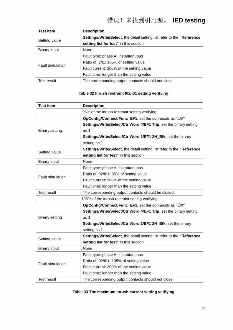
错误!未找到引用源。 IED testing
73
Test item Description
Setting value Settings/Write/Select, the detail setting list refer to the “Reference
setting list for test” in this section
Binary input None
Fault simulation
Fault type: phase A, instantanuous
Ratio of I2/I1: 105% of setting value
Fault current: 200% of the setting value
Fault time: longer than the setting value
Test result The corresponding output contacts should not close
Table 32 Inrush restraint I02/I01 setting verifying
Test item Description
95% of the inrush restraint setting verifying
Binary setting
OpConfig/Connect/Func_EF1, set the connecotr as "On"
Settings/Write/Select/Ctr Word 4/EF1 Trip, set the binary setting
as 1
Settings/Write/Select/Ctr Word 1/EF1 2H_Blk, set the binary
setting as 1
Setting value Settings/Write/Select, the detail setting list refer to the “Reference
setting list for test” in this section
Binary input None
Fault simulation
Fault type: phase A, instantanuous
Ratio of I02/I01: 95% of setting value
Fault current: 200% of the setting value
Fault time: longer than the setting value
Test result The corresponding output contacts should be closed
105% of the inrush restraint setting verifying
Binary setting
OpConfig/Connect/Func_EF1, set the connecotr as "On"
Settings/Write/Select/Ctr Word 4/EF1 Trip, set the binary setting
as 1
Settings/Write/Select/Ctr Word 1/EF1 2H_Blk, set the binary
setting as 1
Setting value Settings/Write/Select, the detail setting list refer to the “Reference
setting list for test” in this section
Binary input None
Fault simulation
Fault type: phase A, instantanuous
Ratio of I02/I01: 105% of setting value
Fault current: 200% of the setting value
Fault time: longer than the setting value
Test result The corresponding output contacts should not close
Table 33 The maximum inrush current setting verifying
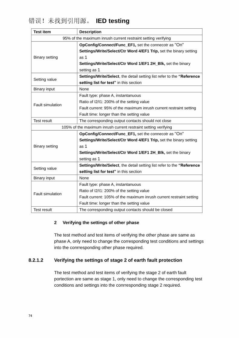
错误!未找到引用源。 IED testing
74
Test item Description
95% of the maximum inrush current restraint setting verifying
Binary setting
OpConfig/Connect/Func_EF1, set the connecotr as "On"
Settings/Write/Select/Ctr Word 4/EF1 Trip, set the binary setting
as 1
Settings/Write/Select/Ctr Word 1/EF1 2H_Blk, set the binary
setting as 1
Setting value Settings/Write/Select, the detail setting list refer to the “Reference
setting list for test” in this section
Binary input None
Fault simulation
Fault type: phase A, instantanuous
Ratio of I2/I1: 200% of the setting value
Fault current: 95% of the maximum inrush current restraint setting
Fault time: longer than the setting value
Test result The corresponding output contacts should not close
105% of the maximum inrush current restraint setting verifying
Binary setting
OpConfig/Connect/Func_EF1, set the connecotr as "On"
Settings/Write/Select/Ctr Word 4/EF1 Trip, set the binary setting
as 1
Settings/Write/Select/Ctr Word 1/EF1 2H_Blk, set the binary
setting as 1
Setting value Settings/Write/Select, the detail setting list refer to the “Reference
setting list for test” in this section
Binary input None
Fault simulation
Fault type: phase A, instantanuous
Ratio of I2/I1: 200% of the setting value
Fault current: 105% of the maximum inrush current restraint setting
Fault time: longer than the setting value
Test result The corresponding output contacts should be closed
2 Verifying the settings of other phase
The test method and test items of verifying the other phase are same as
phase A, only need to change the corresponding test conditions and settings
into the conrresponding other phase required.
8.2.1.2 Verifying the settings of stage 2 of earth fault protection
The test method and test items of verifying the stage 2 of earth fault
portection are same as stage 1, only need to change the corresponding test
conditions and settings into the conrresponding stage 2 required.

错误!未找到引用源。 IED testing
75
8.2.1.3 Verifying the settings of inverse time stage
1 Verifying the phase A setting
1.1 Verifying the current setting
Table 34 Current setting verifying
Test item Description
105% of the current setting verifying
Binary setting
OpConfig/Connect/Func_EF Inv, set the connecotr as "On"
Settings/Write/Select/Ctr Word 4/EF Inv Trip, set the binary
setting as 1
Setting value Settings/Write/Select, the detail setting list refer to the “Reference
setting list for test” in this section
Binary input None
Fault simulation
Fault type: phase A
Fault current: 105% of the setting value
Fault time: longer than the time calculated by the equation
Test result The corresponding output contacts should be closed
95% of the current setting verifying
Binary setting
OpConfig/Connect/Func_EF Inv, set the connecotr as "On"
Settings/Write/Select/Ctr Word 4/EF Inv Trip, set the binary
setting as 1
Setting value Settings/Write/Select, the detail setting list refer to the “Reference
setting list for test” in this section
Binary input None
Fault simulation
Fault type: phase A
Fault current: 95% of the setting value
Fault time: longer than the time calculated by the equation
Test result The corresponding output contacts should not close
1.2 Verifying the time setting
Table 35 Time setting verifying
Test item Description
Binary setting
OpConfig/Connect/Func_EF Inv, set the connecotr as "On"
Settings/Write/Select/Ctr Word 4/EF Inv Trip, set the binary
setting as 1
Setting value Settings/Write/Select, the detail setting list refer to the “Reference
setting list for test” in this section
Binary input None
Fault simulation Fault type: phase A
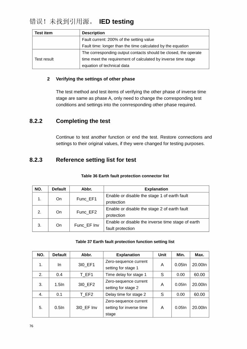
错误!未找到引用源。 IED testing
76
Test item Description
Fault current: 200% of the setting value
Fault time: longer than the time calculated by the equation
Test result
The corresponding output contacts should be closed, the operate
time meet the requirement of calculated by inverse time stage
equation of technical data
2 Verifying the settings of other phase
The test method and test items of verifying the other phase of inverse time
stage are same as phase A, only need to change the corresponding test
conditions and settings into the conrresponding other phase required.
8.2.2 Completing the test
Continue to test another function or end the test. Restore connections and
settings to their original values, if they were changed for testing purposes.
8.2.3 Reference setting list for test
Table 36 Earth fault protection connector list
NO. Default Abbr. Explanation
1. On Func_EF1 Enable or disable the stage 1 of earth fault
protection
2. On Func_EF2 Enable or disable the stage 2 of earth fault
protection
3. On Func_EF Inv Enable or disable the inverse time stage of earth
fault protection
Table 37 Earth fault protection function setting list
NO. Default Abbr. Explanation Unit Min. Max.
1. In 3I0_EF1 Zero-sequence current
setting for stage 1 A 0.05In 20.00In
2. 0.4 T_EF1 Time delay for stage 1 S 0.00 60.00
3. 1.5In 3I0_EF2 Zero-sequence current
setting for stage 2 A 0.05In 20.00In
4. 0.1 T_EF2 Delay time for stage 2 S 0.00 60.00
5. 0.5In 3I0_EF Inv
Zero-sequence current
setting for inverse time
stage
A 0.05In 20.00In
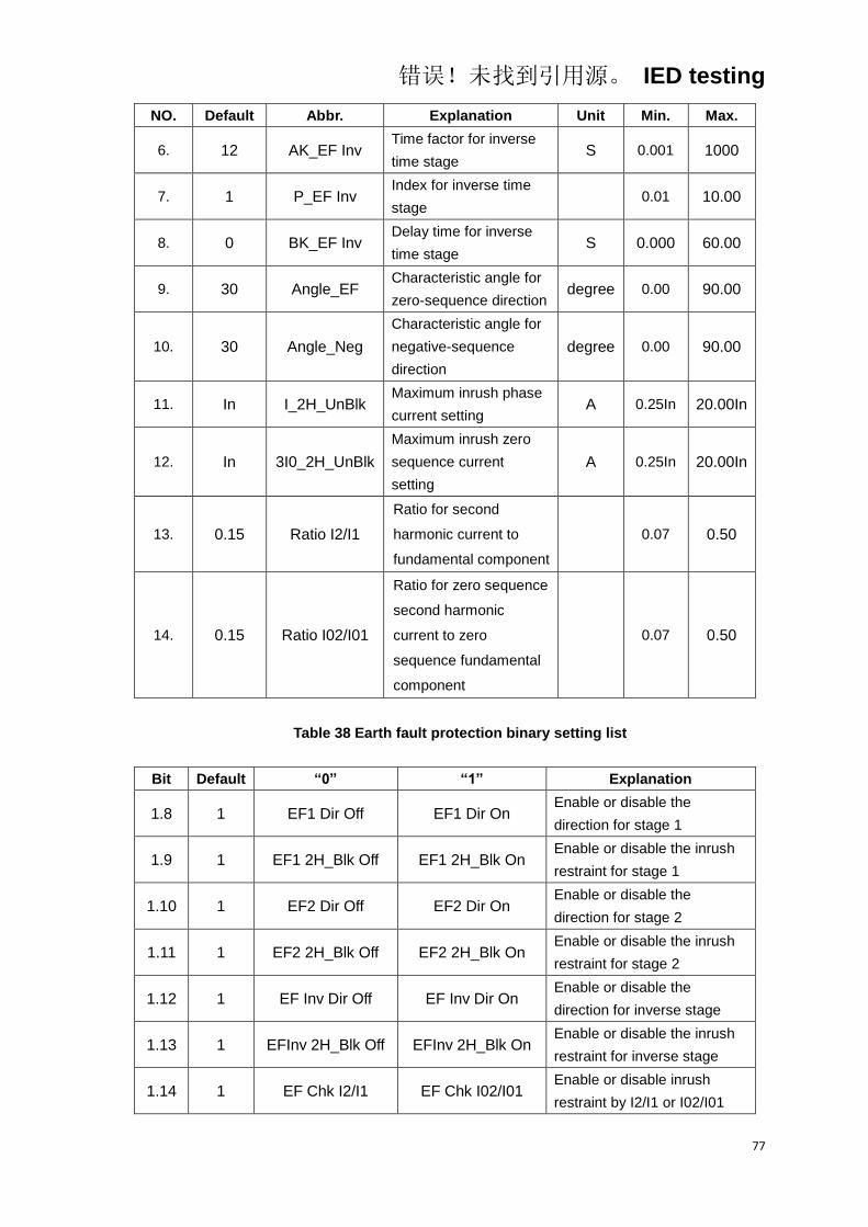
错误!未找到引用源。 IED testing
77
NO. Default Abbr. Explanation Unit Min. Max.
6. 12 AK_EF Inv Time factor for inverse
time stage S 0.001 1000
7. 1 P_EF Inv Index for inverse time
stage 0.01 10.00
8. 0 BK_EF Inv Delay time for inverse
time stage S 0.000 60.00
9. 30 Angle_EF Characteristic angle for
zero-sequence direction degree 0.00 90.00
10. 30 Angle_Neg
Characteristic angle for
negative-sequence
direction
degree 0.00 90.00
11. In I_2H_UnBlk Maximum inrush phase
current setting A 0.25In 20.00In
12. In 3I0_2H_UnBlk
Maximum inrush zero
sequence current
setting
A 0.25In 20.00In
13. 0.15 Ratio I2/I1
Ratio for second
harmonic current to
fundamental component
0.07 0.50
14. 0.15 Ratio I02/I01
Ratio for zero sequence
second harmonic
current to zero
sequence fundamental
component
0.07 0.50
Table 38 Earth fault protection binary setting list
Bit Default “0” “1” Explanation
1.8 1 EF1 Dir Off EF1 Dir On Enable or disable the
direction for stage 1
1.9 1 EF1 2H_Blk Off EF1 2H_Blk On Enable or disable the inrush
restraint for stage 1
1.10 1 EF2 Dir Off EF2 Dir On Enable or disable the
direction for stage 2
1.11 1 EF2 2H_Blk Off EF2 2H_Blk On Enable or disable the inrush
restraint for stage 2
1.12 1 EF Inv Dir Off EF Inv Dir On Enable or disable the
direction for inverse stage
1.13 1 EFInv 2H_Blk Off EFInv 2H_Blk On Enable or disable the inrush
restraint for inverse stage
1.14 1 EF Chk I2/I1 EF Chk I02/I01 Enable or disable inrush
restraint by I2/I1 or I02/I01

错误!未找到引用源。 IED testing
78
Bit Default “0” “1” Explanation
1.15 0 EF U2/I2 Dir Off EF U2/I2 Dir On Enable or disable the
negative sequence direction
2.7 0 3I0 Measured 3I0 Calculated 3I0 measured or calculated
2.8 1 3U0 Measured 3U0 Calculated 3U0 measured or calculated
2.11 0 Blk EF_CT Fail UnBlk EF_CT Fail Enable or disable the function
of CT fail blocking
2.14 1 UnBlk Fun_VT Fail Blk Fun_VT Fail Enable or disable the function
of VT fail blocking
4.2 1 EF1 Alarm EF1 Trip Stage 1 of overcurrent
protection alarm or trip
4.3 1 EF Inv Alarm EF Inv Trip Inverse stage of overcurrent
protection alarm or trip
8.3 Sensitive earth fault protection
Before starting the test, please make sure that the protection function setting
values and parameters are correct, refer to section Introduction, Points for
attention during testing and Preparing for test in this chapter.
8.3.1 Verifying the settings
8.3.1.1 Verifying the settings of sensitive earth fault protection
1 Verifying the phase A setting
1.1 Verifying the current setting
Table 39 Current setting verifying
Test item Description
105% of the current setting verifying
Binary setting
OpConfig/Connect/Func_SEF1, set the connector as "On"
Settings/Write/Select/Ctr Word 4/SEF1 Trip, set the binary setting
as 1
Setting value Settings/Write/Select, the detail setting list refer to the “Reference
setting list for test” in this section
Binary input None
Fault simulation
Fault type: phase A, instantanuous
Sensitive current: 105% of the setting value
Fault time: longer than the setting value
Test result The corresponding output contacts should be closed
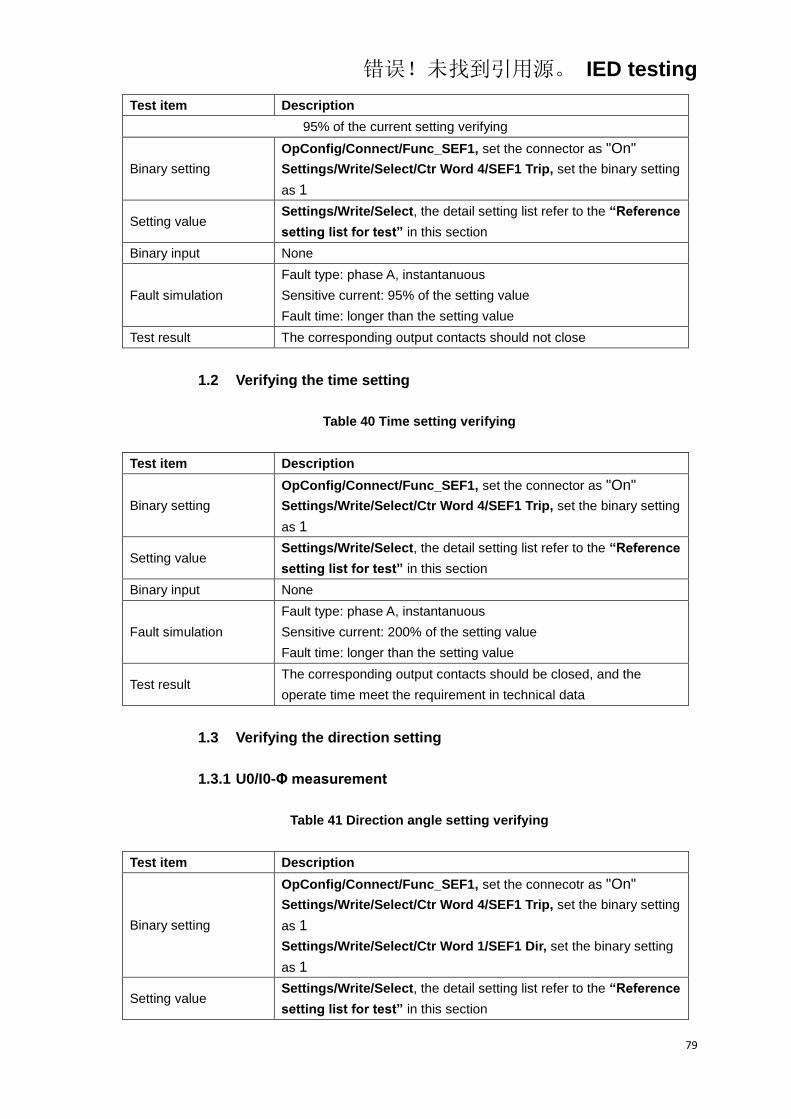
错误!未找到引用源。 IED testing
79
Test item Description
95% of the current setting verifying
Binary setting
OpConfig/Connect/Func_SEF1, set the connector as "On"
Settings/Write/Select/Ctr Word 4/SEF1 Trip, set the binary setting
as 1
Setting value Settings/Write/Select, the detail setting list refer to the “Reference
setting list for test” in this section
Binary input None
Fault simulation
Fault type: phase A, instantanuous
Sensitive current: 95% of the setting value
Fault time: longer than the setting value
Test result The corresponding output contacts should not close
1.2 Verifying the time setting
Table 40 Time setting verifying
Test item Description
Binary setting
OpConfig/Connect/Func_SEF1, set the connector as "On"
Settings/Write/Select/Ctr Word 4/SEF1 Trip, set the binary setting
as 1
Setting value Settings/Write/Select, the detail setting list refer to the “Reference
setting list for test” in this section
Binary input None
Fault simulation
Fault type: phase A, instantanuous
Sensitive current: 200% of the setting value
Fault time: longer than the setting value
Test result The corresponding output contacts should be closed, and the
operate time meet the requirement in technical data
1.3 Verifying the direction setting
1.3.1 U0/I0-Φ measurement
Table 41 Direction angle setting verifying
Test item Description
Binary setting
OpConfig/Connect/Func_SEF1, set the connecotr as "On"
Settings/Write/Select/Ctr Word 4/SEF1 Trip, set the binary setting
as 1
Settings/Write/Select/Ctr Word 1/SEF1 Dir, set the binary setting
as 1
Setting value Settings/Write/Select, the detail setting list refer to the “Reference
setting list for test” in this section
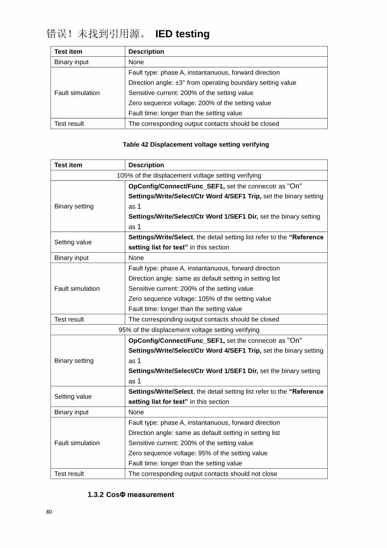
错误!未找到引用源。 IED testing
80
Test item Description
Binary input None
Fault simulation
Fault type: phase A, instantanuous, forward direction
Direction angle: ±3° from operating boundary setting value
Sensitive current: 200% of the setting value
Zero sequence voltage: 200% of the setting value
Fault time: longer than the setting value
Test result The corresponding output contacts should be closed
Table 42 Displacement voltage setting verifying
Test item Description
105% of the displacement voltage setting verifying
Binary setting
OpConfig/Connect/Func_SEF1, set the connecotr as "On"
Settings/Write/Select/Ctr Word 4/SEF1 Trip, set the binary setting
as 1
Settings/Write/Select/Ctr Word 1/SEF1 Dir, set the binary setting
as 1
Setting value Settings/Write/Select, the detail setting list refer to the “Reference
setting list for test” in this section
Binary input None
Fault simulation
Fault type: phase A, instantanuous, forward direction
Direction angle: same as default setting in setting list
Sensitive current: 200% of the setting value
Zero sequence voltage: 105% of the setting value
Fault time: longer than the setting value
Test result The corresponding output contacts should be closed
95% of the displacement voltage setting verifying
Binary setting
OpConfig/Connect/Func_SEF1, set the connecotr as "On"
Settings/Write/Select/Ctr Word 4/SEF1 Trip, set the binary setting
as 1
Settings/Write/Select/Ctr Word 1/SEF1 Dir, set the binary setting
as 1
Setting value Settings/Write/Select, the detail setting list refer to the “Reference
setting list for test” in this section
Binary input None
Fault simulation
Fault type: phase A, instantanuous, forward direction
Direction angle: same as default setting in setting list
Sensitive current: 200% of the setting value
Zero sequence voltage: 95% of the setting value
Fault time: longer than the setting value
Test result The corresponding output contacts should not close
1.3.2 CosΦ measurement

错误!未找到引用源。 IED testing
81
Table 43 Direction angle setting verifying
Test item Description
105% of the IsCosΦ setting value
Binary setting
OpConfig/Connect/Func_SEF1, set the connecotr as "On"
Settings/Write/Select/Ctr Word 4/SEF1 Trip, set the binary setting
as 1
Settings/Write/Select/Ctr Word 1/SEF1 Dir, set the binary setting
as 1
Setting value Settings/Write/Select, the detail setting list refer to the “Reference
setting list for test” in this section
Binary input None
Fault simulation
Fault type: phase A, instantanuous, forward direction
IsCosΦ value: 105% of the setting value
Sensitive current: 200% of the setting value
Zero sequence voltage: 200% of the setting value
Fault time: longer than the setting value
Test result The corresponding output contacts should be closed
95% of the IsCosΦ setting value
Binary setting
OpConfig/Connect/Func_SEF1, set the connecotr as "On"
Settings/Write/Select/Ctr Word 4/SEF1 Trip, set the binary setting
as 1
Settings/Write/Select/Ctr Word 1/SEF1 Dir, set the binary setting
as 1
Setting value Settings/Write/Select, the detail setting list refer to the “Reference
setting list for test” in this section
Binary input None
Fault simulation
Fault type: phase A, instantanuous, forward direction
IsCosΦ value: 95% of the setting value
Sensitive current: 200% of the setting value
Zero sequence voltage: 200% of the setting value
Fault time: longer than the setting value
Test result The corresponding output contacts should be closed
2 Verifying the settings of other phase
The test method and test items of verifying the other phase are same as
phase A, only need to change the corresponding test conditions and settings
into the conrresponding other phase required.
8.3.1.2 Verifying the settings of stage 2 of sensitive earth fault protection
The test method and test items of verifying the stage 2 of sensitive earth fault
portection are same as stage 1, only need to change the corresponding test
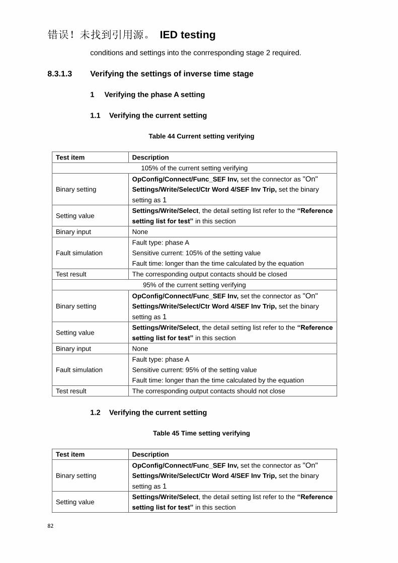
错误!未找到引用源。 IED testing
82
conditions and settings into the conrresponding stage 2 required.
8.3.1.3 Verifying the settings of inverse time stage
1 Verifying the phase A setting
1.1 Verifying the current setting
Table 44 Current setting verifying
Test item Description
105% of the current setting verifying
Binary setting
OpConfig/Connect/Func_SEF Inv, set the connector as "On"
Settings/Write/Select/Ctr Word 4/SEF Inv Trip, set the binary
setting as 1
Setting value Settings/Write/Select, the detail setting list refer to the “Reference
setting list for test” in this section
Binary input None
Fault simulation
Fault type: phase A
Sensitive current: 105% of the setting value
Fault time: longer than the time calculated by the equation
Test result The corresponding output contacts should be closed
95% of the current setting verifying
Binary setting
OpConfig/Connect/Func_SEF Inv, set the connector as "On"
Settings/Write/Select/Ctr Word 4/SEF Inv Trip, set the binary
setting as 1
Setting value Settings/Write/Select, the detail setting list refer to the “Reference
setting list for test” in this section
Binary input None
Fault simulation
Fault type: phase A
Sensitive current: 95% of the setting value
Fault time: longer than the time calculated by the equation
Test result The corresponding output contacts should not close
1.2 Verifying the current setting
Table 45 Time setting verifying
Test item Description
Binary setting
OpConfig/Connect/Func_SEF Inv, set the connector as "On"
Settings/Write/Select/Ctr Word 4/SEF Inv Trip, set the binary
setting as 1
Setting value Settings/Write/Select, the detail setting list refer to the “Reference
setting list for test” in this section

错误!未找到引用源。 IED testing
83
Test item Description
Binary input None
Fault simulation
Fault type: phase A
Sensitive current: 200% of the setting value
Fault time: longer than the time calculated by the equation
Test result
The corresponding output contacts should be closed, the operate
time meet the requirement of calculated by inverse time stage
equation of technical data
2 Verifying the settings of other phase
The test method and test items of verifying the other phase of inverse time
stage are same as phase A, only need to change the corresponding test
conditions and settings into the conrresponding other phase required.
8.3.2 Completing the test
Continue to test another function or end the test. Restore connections and
settings to their original values, if they were changed for testing purposes.
8.3.3 Reference setting list for test
Table 46 Sensitive earth fault protection connector list
NO. Default Abbr. Explanation
1. On Func_SEF1 Enable or disable the stage 1 of sensitive earth fault
protection
2. On Func_SEF2 Enable or disable the stage 2 of sensitive earth fault
protection
3. On Func_SEF Inv Enable or disable the inverse time stage of sensitive
earth fault protection
Table 47 Sensitive earth fault protection function setting list
NO. Default Abbr. Explanation Unit Min. Max.
1. In I_SEF1 Sensitive current
setting for stage 1 A
0.005
(SEF)
0.05In
(Normal)
1.00
(SEF)
20.00In
(Normal)
2. 0.4 T_SEF1 Time delay for stage 1 S 0.00 60.00
3. 1.5In I_SEF2 Sensitive current A 0.005
(SEF)
1.00
(SEF)
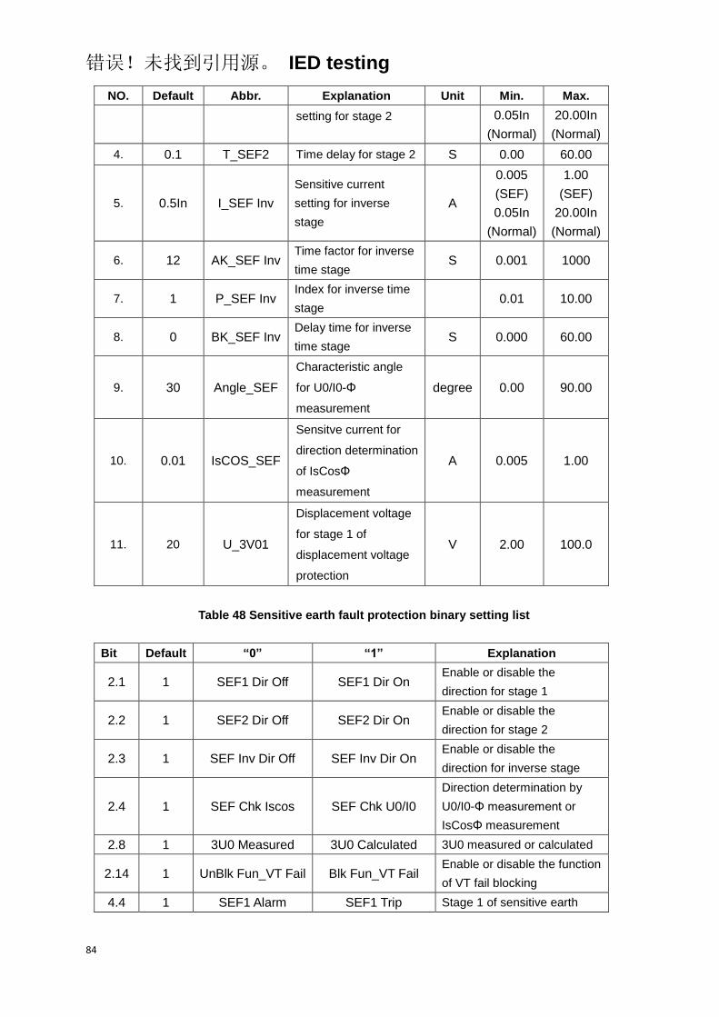
错误!未找到引用源。 IED testing
84
NO. Default Abbr. Explanation Unit Min. Max.
setting for stage 2 0.05In
(Normal)
20.00In
(Normal)
4. 0.1 T_SEF2 Time delay for stage 2 S 0.00 60.00
5. 0.5In I_SEF Inv
Sensitive current
setting for inverse
stage
A
0.005
(SEF)
0.05In
(Normal)
1.00
(SEF)
20.00In
(Normal)
6. 12 AK_SEF Inv Time factor for inverse
time stage S 0.001 1000
7. 1 P_SEF Inv Index for inverse time
stage 0.01 10.00
8. 0 BK_SEF Inv Delay time for inverse
time stage S 0.000 60.00
9. 30 Angle_SEF
Characteristic angle
for U0/I0-Φ
measurement
degree 0.00 90.00
10. 0.01 IsCOS_SEF
Sensitve current for
direction determination
of IsCosΦ
measurement
A 0.005 1.00
11. 20 U_3V01
Displacement voltage
for stage 1 of
displacement voltage
protection
V 2.00 100.0
Table 48 Sensitive earth fault protection binary setting list
Bit Default “0” “1” Explanation
2.1 1 SEF1 Dir Off SEF1 Dir On Enable or disable the
direction for stage 1
2.2 1 SEF2 Dir Off SEF2 Dir On Enable or disable the
direction for stage 2
2.3 1 SEF Inv Dir Off SEF Inv Dir On Enable or disable the
direction for inverse stage
2.4 1 SEF Chk Iscos SEF Chk U0/I0
Direction determination by
U0/I0-Φ measurement or
IsCosΦ measurement
2.8 1 3U0 Measured 3U0 Calculated 3U0 measured or calculated
2.14 1 UnBlk Fun_VT Fail Blk Fun_VT Fail Enable or disable the function
of VT fail blocking
4.4 1 SEF1 Alarm SEF1 Trip Stage 1 of sensitive earth

错误!未找到引用源。 IED testing
85
Bit Default “0” “1” Explanation
fault protection alarm or trip
4.5 1 SEF2 Alarm SEF2 Trip Stage 2 of sensitive earth
fault protection alarm or trip
4.6 1 SEF Inv Alarm SEF Inv Trip
Inverse stage of sensitive
earth fault protection alarm or
trip
8.4 Negative sequence overcurrent protection
Before starting the test, please make sure that the protection function setting
values and parameters are correct, refer to section Introduction, Points for
attention during testing and Preparing for test in this chapter.
8.4.1 Verifying the settings
8.4.1.1 Verifying the settings of negative sequence overcurrent
protection
1 Verifying the phase A setting
1.1 Verifying the negative sequence current setting
Table 49 Negative sequence current setting verifying
Test item Description
105% of the negative sequence current setting verifying
Binary setting
OpConfig/Connect/Func_NSOC1, set the connector as "On"
Settings/Write/Select/Ctr Word 4/NSOC1 Trip, set the binary
setting as 1
Setting value Settings/Write/Select, the detail setting list refer to the “Reference
setting list for test” in this section
Binary input None
Fault simulation
Fault type: phase A, instantanuous
Fault current: 105% of the setting value
Fault time: longer than the setting value
Test result The corresponding output contacts should be closed
95% of the negative sequence current setting verifying
Binary setting
OpConfig/Connect/Func_NSOC1, set the connector as "On"
Settings/Write/Select/Ctr Word 4/NSOC1 Trip, set the binary
setting as 1
Setting value Settings/Write/Select, the detail setting list refer to the “Reference
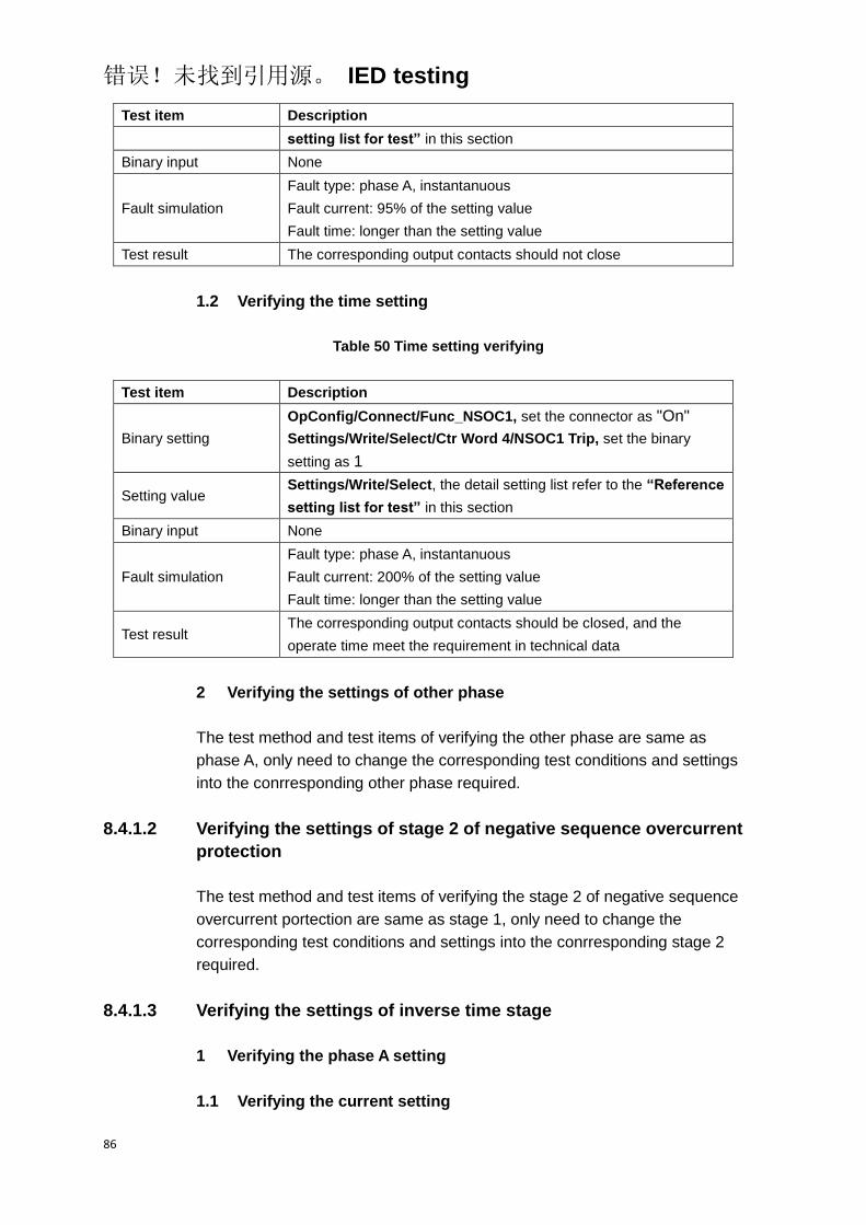
错误!未找到引用源。 IED testing
86
Test item Description
setting list for test” in this section
Binary input None
Fault simulation
Fault type: phase A, instantanuous
Fault current: 95% of the setting value
Fault time: longer than the setting value
Test result The corresponding output contacts should not close
1.2 Verifying the time setting
Table 50 Time setting verifying
Test item Description
Binary setting
OpConfig/Connect/Func_NSOC1, set the connector as "On"
Settings/Write/Select/Ctr Word 4/NSOC1 Trip, set the binary
setting as 1
Setting value Settings/Write/Select, the detail setting list refer to the “Reference
setting list for test” in this section
Binary input None
Fault simulation
Fault type: phase A, instantanuous
Fault current: 200% of the setting value
Fault time: longer than the setting value
Test result The corresponding output contacts should be closed, and the
operate time meet the requirement in technical data
2 Verifying the settings of other phase
The test method and test items of verifying the other phase are same as
phase A, only need to change the corresponding test conditions and settings
into the conrresponding other phase required.
8.4.1.2 Verifying the settings of stage 2 of negative sequence overcurrent
protection
The test method and test items of verifying the stage 2 of negative sequence
overcurrent portection are same as stage 1, only need to change the
corresponding test conditions and settings into the conrresponding stage 2
required.
8.4.1.3 Verifying the settings of inverse time stage
1 Verifying the phase A setting
1.1 Verifying the current setting
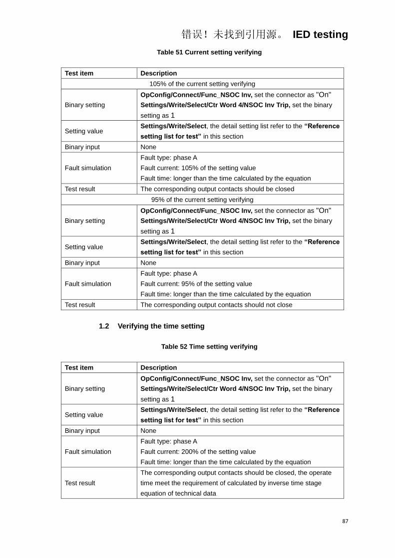
错误!未找到引用源。 IED testing
87
Table 51 Current setting verifying
Test item Description
105% of the current setting verifying
Binary setting
OpConfig/Connect/Func_NSOC Inv, set the connector as "On"
Settings/Write/Select/Ctr Word 4/NSOC Inv Trip, set the binary
setting as 1
Setting value Settings/Write/Select, the detail setting list refer to the “Reference
setting list for test” in this section
Binary input None
Fault simulation
Fault type: phase A
Fault current: 105% of the setting value
Fault time: longer than the time calculated by the equation
Test result The corresponding output contacts should be closed
95% of the current setting verifying
Binary setting
OpConfig/Connect/Func_NSOC Inv, set the connector as "On"
Settings/Write/Select/Ctr Word 4/NSOC Inv Trip, set the binary
setting as 1
Setting value Settings/Write/Select, the detail setting list refer to the “Reference
setting list for test” in this section
Binary input None
Fault simulation
Fault type: phase A
Fault current: 95% of the setting value
Fault time: longer than the time calculated by the equation
Test result The corresponding output contacts should not close
1.2 Verifying the time setting
Table 52 Time setting verifying
Test item Description
Binary setting
OpConfig/Connect/Func_NSOC Inv, set the connector as "On"
Settings/Write/Select/Ctr Word 4/NSOC Inv Trip, set the binary
setting as 1
Setting value Settings/Write/Select, the detail setting list refer to the “Reference
setting list for test” in this section
Binary input None
Fault simulation
Fault type: phase A
Fault current: 200% of the setting value
Fault time: longer than the time calculated by the equation
Test result
The corresponding output contacts should be closed, the operate
time meet the requirement of calculated by inverse time stage
equation of technical data

错误!未找到引用源。 IED testing
88
2 Verifying the settings of other phase
The test method and test items of verifying the other phase of inverse time
stage are same as phase A, only need to change the corresponding test
conditions and settings into the other phase required.
8.4.2 Completing the test
Continue to test another function or end the test. Restore connections and
settings to their original values, if they were changed for testing purposes.
8.4.3 Reference setting list for test
Table 53 Negative sequence overcurrent protection connector list
NO. Default Abbr. Explanation
1. On Func_NSOC1 Enable or disable the stage 1 of negative sequence
protection
2. On Func_NSOC2 Enable or disable the stage 2 of negative sequence
protection
3. On Func_NSOC Inv Enable or disable the inverse time stage of negative
sequence protection
Table 54 Negative sequence overcurrent protection function setting list
NO. Default Abbr. Explanation Unit Min. Max.
1. In 3I2_NSOC1 Negative sequence current
setting for stage 1 A 0.05In 20.00In
2. 0.4 T_NSOC1 Time delay for stage 1 S 0.00 60.00
3. 1.5In 3I2_NSOC2 Negative sequence current
setting for stage 2 A 0.05In 20.00In
4. 0.1 T_NSOC2 Time delay for stage 2 S 0.00 60.00
5. 0.5In 3I2_NSOC Inv Negative sequence current
setting for inverse stage A 0.05In 20.00In
6. 0.056 AK_NSOC Inv Time factor for inverse time
stage S 0.001 1000
7. 0.02 P_NSOC Inv Index for inverse time stage 0.01 10.00
8. 0 BK_NSOC Inv Delay time for inverse time
stage S 0.000 60.00
Table 55 Negative sequence overcurrent protection binary setting list

错误!未找到引用源。 IED testing
89
Bit Default “0” “1” Explanation
4.7 1 NSOC1 Alarm NSOC1 Trip
Stage 1 of negative sequence
overcurrent protection alarm
or trip
4.8 1 NSOC Inv Alarm NSOC Inv Trip
Inverse stage of negative
sequence overcurrent
protection alarm or trip
8.5 Switch-onto-fault protection
Before starting the test, please make sure that the protection function setting
values and parameters are correct, refer to section Introduction, Points for
attention during testing and Preparing for test in this chapter.
8.5.1 Verifying the settings
8.5.1.1 Verifying the overcurrent element of switch-onto-fault protection
1 Verifying the phase A setting
1.1 Verifying the current setting
Table 56 Current setting verifying
Test item Description
105% of the current setting verifying
Binary setting
OpConfig/Connect/Func_OC1, set the connector as "On"
Settings/Write/Select/Ctr Word 2/SOFT On, set the binary setting
as 1
Settings/Write/Select/Ctr Word 4/OC1 Trip, set the binary setting
as 1
Setting value Settings/Write/Select, the detail setting list refer to the “Reference
setting list for test” in this section
Binary input Active the binary input of manual reclosure
Fault simulation
Fault type: phase A, instantanuous
Fault current: 105% of the setting value
Fault time: longer than the setting value
Test result The corresponding output contacts should be closed
95% of the current setting verifying
Binary setting
OpConfig/Connect/Func_OC1, set the connector as "On"
Settings/Write/Select/Ctr Word 2/SOFT On, set the binary setting
as 1
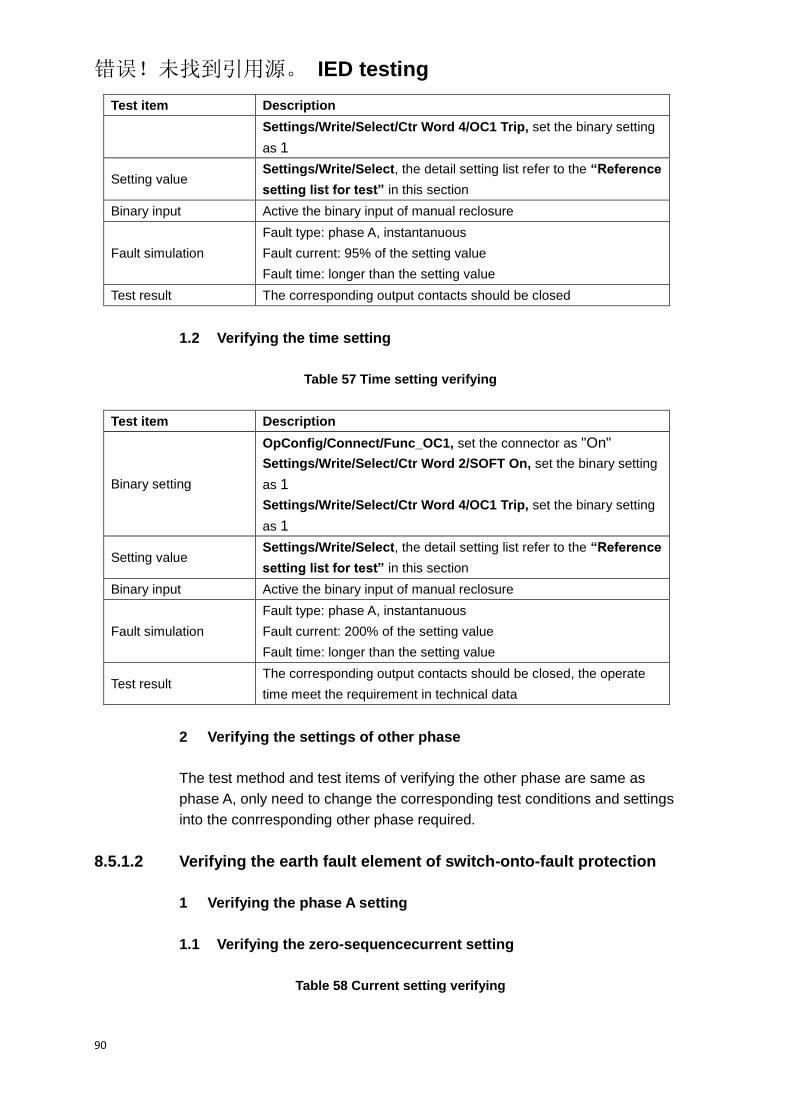
错误!未找到引用源。 IED testing
90
Test item Description
Settings/Write/Select/Ctr Word 4/OC1 Trip, set the binary setting
as 1
Setting value Settings/Write/Select, the detail setting list refer to the “Reference
setting list for test” in this section
Binary input Active the binary input of manual reclosure
Fault simulation
Fault type: phase A, instantanuous
Fault current: 95% of the setting value
Fault time: longer than the setting value
Test result The corresponding output contacts should be closed
1.2 Verifying the time setting
Table 57 Time setting verifying
Test item Description
Binary setting
OpConfig/Connect/Func_OC1, set the connector as "On"
Settings/Write/Select/Ctr Word 2/SOFT On, set the binary setting
as 1
Settings/Write/Select/Ctr Word 4/OC1 Trip, set the binary setting
as 1
Setting value Settings/Write/Select, the detail setting list refer to the “Reference
setting list for test” in this section
Binary input Active the binary input of manual reclosure
Fault simulation
Fault type: phase A, instantanuous
Fault current: 200% of the setting value
Fault time: longer than the setting value
Test result The corresponding output contacts should be closed, the operate
time meet the requirement in technical data
2 Verifying the settings of other phase
The test method and test items of verifying the other phase are same as
phase A, only need to change the corresponding test conditions and settings
into the conrresponding other phase required.
8.5.1.2 Verifying the earth fault element of switch-onto-fault protection
1 Verifying the phase A setting
1.1 Verifying the zero-sequencecurrent setting
Table 58 Current setting verifying

错误!未找到引用源。 IED testing
91
Test item Description
105% of the current setting verifying
Binary setting
OpConfig/Connect/Func_EF1, set the connector as "On"
Settings/Write/Select/Ctr Word 2/SOFT On, set the binary setting
as 1
Settings/Write/Select/Ctr Word 4/EF1 Trip, set the binary setting
as 1
Setting value Settings/Write/Select, the detail setting list refer to the “Reference
setting list for test” in this section
Binary input Active the binary input of manual reclosure
Fault simulation
Fault type: phase A, instantanuous
Fault current: 105% of the setting value
Fault time: longer than the setting value
Test result The corresponding output contacts should be closed
95% of the current setting verifying
Binary setting
OpConfig/Connect/Func_EF1, set the connector as "On"
Settings/Write/Select/Ctr Word 2/SOFT On, set the binary setting
as 1
Settings/Write/Select/Ctr Word 4/EF1 Trip, set the binary setting
as 1
Setting value Settings/Write/Select, the detail setting list refer to the “Reference
setting list for test” in this section
Binary input Active the binary input of manual reclosure
Fault simulation
Fault type: phase A, instantanuous
Fault current: 95% of the setting value
Fault time: longer than the setting value
Test result The corresponding output contacts should be closed
1.2 Verifying the time setting
Table 59 Time setting verifying
Test item Description
Binary setting
OpConfig/Connect/Func_EF1, set the connector as "On"
Settings/Write/Select/Ctr Word 2/SOFT On, set the binary setting
as 1
Settings/Write/Select/Ctr Word 4/EF1 Trip, set the binary setting
as 1
Setting value Settings/Write/Select, the detail setting list refer to the “Reference
setting list for test” in this section
Binary input Active the binary input of manual reclosure
Fault simulation
Fault type: phase A, instantanuous
Fault current: 200% of the setting value
Fault time: longer than the setting value
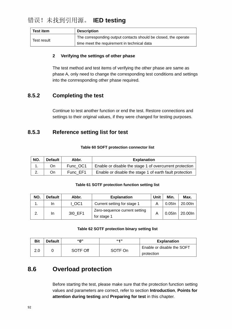
错误!未找到引用源。 IED testing
92
Test item Description
Test result The corresponding output contacts should be closed, the operate
time meet the requirement in technical data
2 Verifying the settings of other phase
The test method and test items of verifying the other phase are same as
phase A, only need to change the corresponding test conditions and settings
into the conrresponding other phase required.
8.5.2 Completing the test
Continue to test another function or end the test. Restore connections and
settings to their original values, if they were changed for testing purposes.
8.5.3 Reference setting list for test
Table 60 SOFT protection connector list
NO. Default Abbr. Explanation
1. On Func_OC1 Enable or disable the stage 1 of overcurrent protection
2. On Func_EF1 Enable or disable the stage 1 of earth fault protection
Table 61 SOTF protection function setting list
NO. Default Abbr. Explanation Unit Min. Max.
1. In I_OC1 Current setting for stage 1 A 0.05In 20.00In
2. In 3I0_EF1 Zero-sequence current setting
for stage 1 A 0.05In 20.00In
Table 62 SOTF protection binary setting list
Bit Default “0” “1” Explanation
2.0 0 SOTF Off SOTF On Enable or disable the SOFT
protection
8.6 Overload protection
Before starting the test, please make sure that the protection function setting
values and parameters are correct, refer to section Introduction, Points for
attention during testing and Preparing for test in this chapter.

错误!未找到引用源。 IED testing
93
8.6.1 Verifying the settings
1 Verifying the phase A setting
1.1 Verifying the current setting
Table 63 Current setting for trip verifying
Test item Description
105% of the current setting verifying
Binary setting OpConfig/Connect/Func_OL, set the connector as "On"
Setting value Settings/Write/Select, the detail setting list refer to the “Reference
setting list for test” in this section
Binary input None
Fault simulation
Fault type: phase A
Fault current: 105% of the setting value
Fault time: longer than the setting value
Test result The corresponding output contacts should be closed
95% of the current setting verifying
Binary setting OpConfig/Connect/Func_OL, set the connector as "On"
Setting value Settings/Write/Select, the detail setting list refer to the “Reference
setting list for test” in this section
Binary input None
Fault simulation
Fault type: phase A
Fault current: 95% of the setting value
Fault time: longer than the setting value
Test result The corresponding output contacts should not close
Table 64 Current setting for alarm verifying
Test item Description
105% of the current setting verifying
Binary setting
OpConfig/Connect/Func_OL, set the connector as "On"
Settings/Write/Select/Ctr Word 4/OL Alarm On, set the binary
setting as 1
Setting value Settings/Write/Select, the detail setting list refer to the “Reference
setting list for test” in this section
Binary input None
Fault simulation
Fault type: phase A
Fault current: 105% of the setting value
Fault time: longer than the setting value
Test result The alarm should be issued
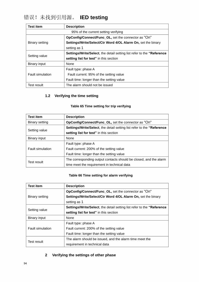
错误!未找到引用源。 IED testing
94
Test item Description
95% of the current setting verifying
Binary setting
OpConfig/Connect/Func_OL, set the connector as "On"
Settings/Write/Select/Ctr Word 4/OL Alarm On, set the binary
setting as 1
Setting value Settings/Write/Select, the detail setting list refer to the “Reference
setting list for test” in this section
Binary input None
Fault simulation
Fault type: phase A
Fault current: 95% of the setting value
Fault time: longer than the setting value
Test result The alarm should not be issued
1.2 Verifying the time setting
Table 65 Time setting for trip verifying
Test item Description
Binary setting OpConfig/Connect/Func_OL, set the connector as "On"
Setting value Settings/Write/Select, the detail setting list refer to the “Reference
setting list for test” in this section
Binary input None
Fault simulation
Fault type: phase A
Fault current: 200% of the setting value
Fault time: longer than the setting value
Test result The corresponding output contacts should be closed, and the alarm
time meet the requirement in technical data
Table 66 Time setting for alarm verifying
Test item Description
Binary setting
OpConfig/Connect/Func_OL, set the connector as "On"
Settings/Write/Select/Ctr Word 4/OL Alarm On, set the binary
setting as 1
Setting value Settings/Write/Select, the detail setting list refer to the “Reference
setting list for test” in this section
Binary input None
Fault simulation
Fault type: phase A
Fault current: 200% of the setting value
Fault time: longer than the setting value
Test result The alarm should be issued, and the alarm time meet the
requirement in technical data
2 Verifying the settings of other phase

错误!未找到引用源。 IED testing
95
The test method and test items of verifying the other phase are same as
phase A, only need to change the corresponding test conditions and settings
into the conrresponding other phase required.
8.6.2 Completing the test
Continue to test another function or end the test. Restore connections and
settings to their original values, if they were changed for testing purposes.
8.6.3 Reference setting list for test
Table 67 Overload protection connector list
NO. Default Abbr. Explanation
1. On Func_OL Enable or disable the overload protection
Table 68 Overload protection function setting list
NO. Default Abbr. Explanation Unit Min. Max.
1. 1.5In I_OL Alarm Current setting for alarm of
overload protection A 0.05In 20.00In
2. 5 T_OL Alarm Time setting for alarm of
overload protection s 0.10 6000.0
3. 1.2In I_OL Trip Current setting for trip of
overload protection A 0.05In 20.00In
4. 10 T_OL Trip Time setting for trip of overload
protection s 0.10 6000.0
Table 69 Overload protection binary setting list
Bit Default “0” “1” Explanation
4.7 1 OL Alarm Off OL Alarm On Enable or disable the alarm
function of overload protection
8.7 Overvoltage protection
Before starting the test, please make sure that the protection function setting
values and parameters are correct, refer to section Introduction, Points for
attention during testing and Preparing for test in this chapter.

错误!未找到引用源。 IED testing
96
8.7.1 Verifying the settings
8.7.1.1 Verifying the settings of stage 1 of overvoltage protection
1 Phase-to-earth voltage discrimination
1.1 Verifying the phase A settings
1.1.1 Verifying the voltage setting
Table 70 Voltage setting verifying
Test item Description
105% of the voltage setting verifying
Binary setting
OpConfig/Connect/Func_OV1, set the connector as "On"
Settings/Write/Select/Ctr Word 4/OV1 Trip, set the binary setting
as 1
Settings/Write/Select/Ctr Word 3/OV PE, set the binary setting as
1
Setting value Settings/Write/Select, the detail setting list refer to the “Reference
setting list for test” in this section
Binary input None
Fault simulation
Overvoltage phase: phase A
Overvoltage value: 105% of the setting value
Overvoltage time: longer than the setting value
Test result The corresponding output contacts should be closed
95% of the voltage setting verifying
Binary setting
OpConfig/Connect/Func_OV1, set the connector as "On"
Settings/Write/Select/Ctr Word 4/OV1 Trip, set the binary setting
as 1
Settings/Write/Select/Ctr Word 3/OV PE, set the binary setting as
1
Setting value Settings/Write/Select, the detail setting list refer to the “Reference
setting list for test” in this section
Binary input None
Fault simulation
Overvoltage phase: phase A
Overvoltage value: 95% of the setting value
Overvoltage time: longer than the setting value
Test result The corresponding output contacts should not close
1.1.2 Veritying the time setting
Table 71 Time setting verifying

错误!未找到引用源。 IED testing
97
Test item Description
Binary setting
OpConfig/Connect/Func_OV1, set the connector as "On"
Settings/Write/Select/Ctr Word 4/OV1 Trip, set the binary setting
as 1
Settings/Write/Select/Ctr Word 3/OV PE, set the binary setting as
1
Setting value Settings/Write/Select, the detail setting list refer to the “Reference
setting list for test” in this section
Binary input None
Fault simulation
Overvoltage phase: phase A
Overvoltage value: 120% of the setting value
Overvoltage time: longer than the setting value
Test result The corresponding output contacts should be closed, and the
operate time meet the requirement in technical data
1.1.3 Veritying the dropout ratio setting
Table 72 Dropout ratio setting verifying
Test item Description
101% of the dropout ratio setting verifying
Binary setting
OpConfig/Connect/Func_OV1, set the connector as "On"
Settings/Write/Select/Ctr Word 4/OV1 Trip, set the binary setting
as 1
Settings/Write/Select/Ctr Word 3/OV PE, set the binary setting as
1
Setting value Settings/Write/Select, the detail setting list refer to the “Reference
setting list for test” in this section
Binary input None
Fault simulation
Overvoltage phase: phase A
Overvoltage value: 120% of the setting value
Overvoltage time: longer than the setting value
Dropout ratio: 101% of the setting value
Test result The protection function does not dropout
99% of the voltage setting verifying
Binary setting
Settings/ProtContwd/Pls Input SetGrNo/Voltage/Func_OV1, set
the binary setting as 1
Settings/ProtContwd/Pls Input SetGrNo/Voltage/OV PE, set the
binary setting as 1
Settings/ProtContwd/Pls Input SetGrNo/Voltage/OV1 Trip, set
the binary setting as 1
Setting value Settings/ProtSet/Pls Input SetGrNo/Current, the detail setting list
refer to the “Reference setting list for test” in this section
Binary input None

错误!未找到引用源。 IED testing
98
Test item Description
Fault simulation
Overvoltage phase: phase A
Overvoltage value: 120% of the setting value
Overvoltage time: longer than the setting value
Dropout ratio: 99% of the setting value
Test result The protection function dropout
1.2 Verifying the settings of other phase
The test method and test items of verifying the other phase are same as
phase A, only need to change the corresponding test conditions and settings
into the conrresponding other phase required.
2 Phase-to-phase voltage discrimination
2.1 Verifying the phase AB settings
2.1.1 Verifying the voltage setting
Table 73 Voltage setting verifying
Test item Description
105% of the voltage setting verifying
Binary setting
OpConfig/Connect/Func_OV1, set the connector as "On"
Settings/Write/Select/Ctr Word 4/OV1 Trip, set the binary setting
as 1
Settings/Write/Select/Ctr Word 3/OV PP, set the binary setting as
1
Setting value Settings/Write/Select, the detail setting list refer to the “Reference
setting list for test” in this section
Binary input None
Fault simulation
Overvoltage phase: phase AB
Overvoltage value: 105% of the setting value
Overvoltage time: longer than the setting value
Test result The corresponding output contacts should be closed
95% of the voltage setting verifying
Binary setting
OpConfig/Connect/Func_OV1, set the connector as "On"
Settings/Write/Select/Ctr Word 4/OV1 Trip, set the binary setting
as 1
Settings/Write/Select/Ctr Word 3/OV PP, set the binary setting as
1
Setting value Settings/Write/Select, the detail setting list refer to the “Reference
setting list for test” in this section
Binary input None
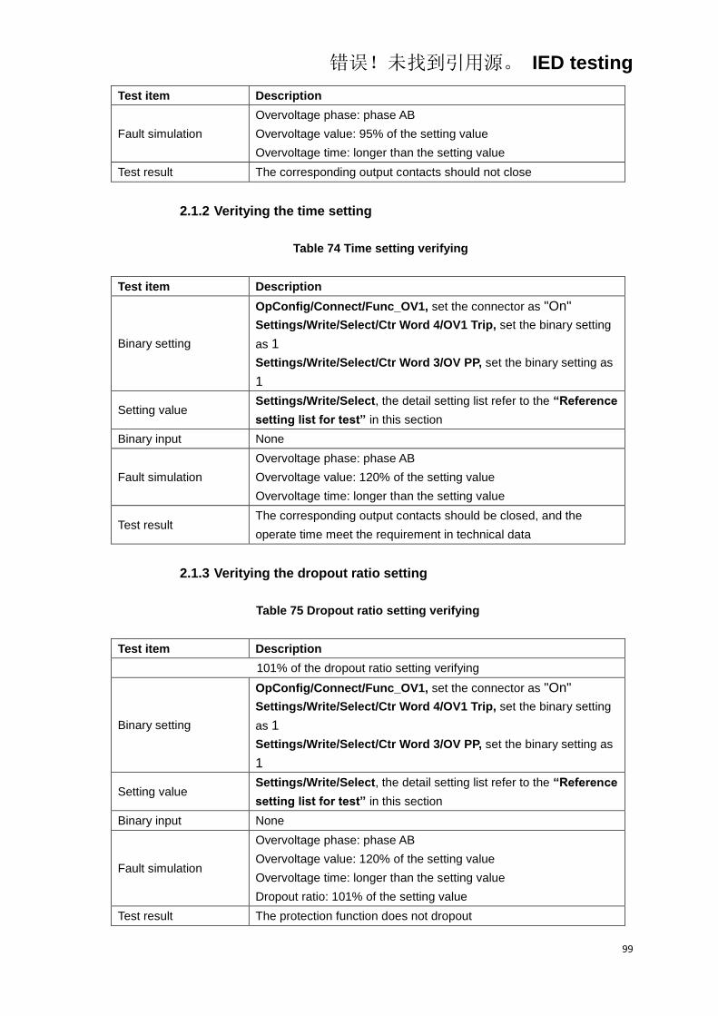
错误!未找到引用源。 IED testing
99
Test item Description
Fault simulation
Overvoltage phase: phase AB
Overvoltage value: 95% of the setting value
Overvoltage time: longer than the setting value
Test result The corresponding output contacts should not close
2.1.2 Veritying the time setting
Table 74 Time setting verifying
Test item Description
Binary setting
OpConfig/Connect/Func_OV1, set the connector as "On"
Settings/Write/Select/Ctr Word 4/OV1 Trip, set the binary setting
as 1
Settings/Write/Select/Ctr Word 3/OV PP, set the binary setting as
1
Setting value Settings/Write/Select, the detail setting list refer to the “Reference
setting list for test” in this section
Binary input None
Fault simulation
Overvoltage phase: phase AB
Overvoltage value: 120% of the setting value
Overvoltage time: longer than the setting value
Test result The corresponding output contacts should be closed, and the
operate time meet the requirement in technical data
2.1.3 Veritying the dropout ratio setting
Table 75 Dropout ratio setting verifying
Test item Description
101% of the dropout ratio setting verifying
Binary setting
OpConfig/Connect/Func_OV1, set the connector as "On"
Settings/Write/Select/Ctr Word 4/OV1 Trip, set the binary setting
as 1
Settings/Write/Select/Ctr Word 3/OV PP, set the binary setting as
1
Setting value Settings/Write/Select, the detail setting list refer to the “Reference
setting list for test” in this section
Binary input None
Fault simulation
Overvoltage phase: phase AB
Overvoltage value: 120% of the setting value
Overvoltage time: longer than the setting value
Dropout ratio: 101% of the setting value
Test result The protection function does not dropout
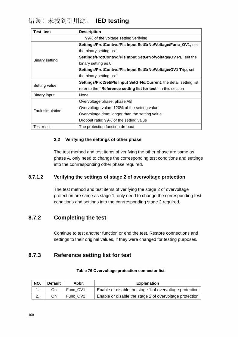
错误!未找到引用源。 IED testing
100
Test item Description
99% of the voltage setting verifying
Binary setting
Settings/ProtContwd/Pls Input SetGrNo/Voltage/Func_OV1, set
the binary setting as 1
Settings/ProtContwd/Pls Input SetGrNo/Voltage/OV PE, set the
binary setting as 0
Settings/ProtContwd/Pls Input SetGrNo/Voltage/OV1 Trip, set
the binary setting as 1
Setting value Settings/ProtSet/Pls Input SetGrNo/Current, the detail setting list
refer to the “Reference setting list for test” in this section
Binary input None
Fault simulation
Overvoltage phase: phase AB
Overvoltage value: 120% of the setting value
Overvoltage time: longer than the setting value
Dropout ratio: 99% of the setting value
Test result The protection function dropout
2.2 Verifying the settings of other phase
The test method and test items of verifying the other phase are same as
phase A, only need to change the corresponding test conditions and settings
into the conrresponding other phase required.
8.7.1.2 Verifying the settings of stage 2 of overvoltage protection
The test method and test items of verifying the stage 2 of overvoltage
protection are same as stage 1, only need to change the corresponding test
conditions and settings into the conrresponding stage 2 required.
8.7.2 Completing the test
Continue to test another function or end the test. Restore connections and
settings to their original values, if they were changed for testing purposes.
8.7.3 Reference setting list for test
Table 76 Overvoltage protection connector list
NO. Default Abbr. Explanation
1. On Func_OV1 Enable or disable the stage 1 of overvoltage protection
2. On Func_OV2 Enable or disable the stage 2 of overvoltage protection

错误!未找到引用源。 IED testing
101
Table 77 Overvoltage protection function setting list
NO. Default Abbr. Explanation Unit Min. Max.
1. 70 U_OV1 Voltage setting for stage 1 of
overvoltage protection V
40.00
(PE)
80.00
(PP)
100.0
(PE)
200.0
(PP)
2. 0.1 T_OV1 Time setting for stage 1 of
overvoltage protection s 0.00 60.00
3. 70 U_OV2 Voltage setting for stage 2 of
overvoltage protection V
40.00
(PE)
80.00
(PP)
100.0
(PE)
200.0
(PP)
4. 0.1 T_OV2 Time setting for stage 2 of
overvoltage protection s 0.00 60.00
5. 0.95 Dropout_OV Dropout ratio for overvoltage
protection 0.90 0.99
Table 78 Overvoltage protection binary setting list
Bit Default “0” “1” Explanation
3.3 1 OV PP OV PE
Phase-to-phase or
phase-to-earth discrimination
for overvoltage protection
4.12 1 OV1 Alarm OV1 Trip Stage 1 of overvoltage
protection alarm or trip
8.8 Undervoltage protection
Before starting the test, please make sure that the protection function setting
values and parameters are correct, refer to section Introduction, Points for
attention during testing and Preparing for test in this chapter.
8.8.1 Verifying the settings
8.8.1.1 Verifying the settings of stage 1 of undervoltage protection
1 Phase-to-earth voltage discrimination
1.1 Verifying the phase A settings
1.1.1 Verifying the voltage setting

错误!未找到引用源。 IED testing
102
Table 79 Voltage setting verifying
Test item Description
95% of the voltage setting verifying
Binary setting
OpConfig/Connect/Func_UV1, set the connector as "On"
Settings/Write/Select/Ctr Word 4/UV1 Trip, set the binary setting
as 1
Settings/Write/Select/Ctr Word 3/UV PE, set the binary setting as
1
Setting value Settings/Write/Select, the detail setting list refer to the “Reference
setting list for test” in this section
Binary input None
Fault simulation
Undervoltage phase: phase A
Undervoltage value: 95% of the setting value
Current value: 200% of the setting value
Undervoltage time: longer than the setting value
Test result The corresponding output contacts should be closed
105% of the voltage setting verifying
Binary setting
OpConfig/Connect/Func_UV1, set the connector as "On"
Settings/Write/Select/Ctr Word 4/UV1 Trip, set the binary setting
as 1
Settings/Write/Select/Ctr Word 3/UV PE, set the binary setting as
1
Setting value Settings/Write/Select, the detail setting list refer to the “Reference
setting list for test” in this section
Binary input None
Fault simulation
Undervoltage phase: phase A
Undervoltage value: 105% of the setting value
Current value: 200% of the setting value
Undervoltage time: longer than the setting value
Test result The corresponding output contacts should not close
1.1.2 Verifying the time setting
Table 80 Time setting verifying
Test item Description
Binary setting
OpConfig/Connect/Func_UV1, set the connector as "On"
Settings/Write/Select/Ctr Word 4/UV1 Trip, set the binary setting
as 1
Settings/Write/Select/Ctr Word 3/UV PE, set the binary setting as
1
Setting value Settings/Write/Select, the detail setting list refer to the “Reference
setting list for test” in this section
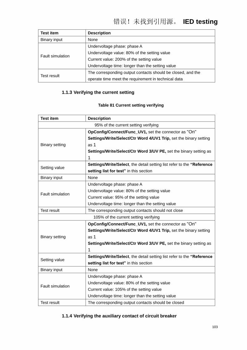
错误!未找到引用源。 IED testing
103
Test item Description
Binary input None
Fault simulation
Undervoltage phase: phase A
Undervoltage value: 80% of the setting value
Current value: 200% of the setting value
Undervoltage time: longer than the setting value
Test result The corresponding output contacts should be closed, and the
operate time meet the requirement in technical data
1.1.3 Verifying the current setting
Table 81 Current setting verifying
Test item Description
95% of the current setting verifying
Binary setting
OpConfig/Connect/Func_UV1, set the connector as "On"
Settings/Write/Select/Ctr Word 4/UV1 Trip, set the binary setting
as 1
Settings/Write/Select/Ctr Word 3/UV PE, set the binary setting as
1
Setting value Settings/Write/Select, the detail setting list refer to the “Reference
setting list for test” in this section
Binary input None
Fault simulation
Undervoltage phase: phase A
Undervoltage value: 80% of the setting value
Current value: 95% of the setting value
Undervoltage time: longer than the setting value
Test result The corresponding output contacts should not close
105% of the current setting verifying
Binary setting
OpConfig/Connect/Func_UV1, set the connector as "On"
Settings/Write/Select/Ctr Word 4/UV1 Trip, set the binary setting
as 1
Settings/Write/Select/Ctr Word 3/UV PE, set the binary setting as
1
Setting value Settings/Write/Select, the detail setting list refer to the “Reference
setting list for test” in this section
Binary input None
Fault simulation
Undervoltage phase: phase A
Undervoltage value: 80% of the setting value
Current value: 105% of the setting value
Undervoltage time: longer than the setting value
Test result The corresponding output contacts should be closed
1.1.4 Verifying the auxiliary contact of circuit breaker
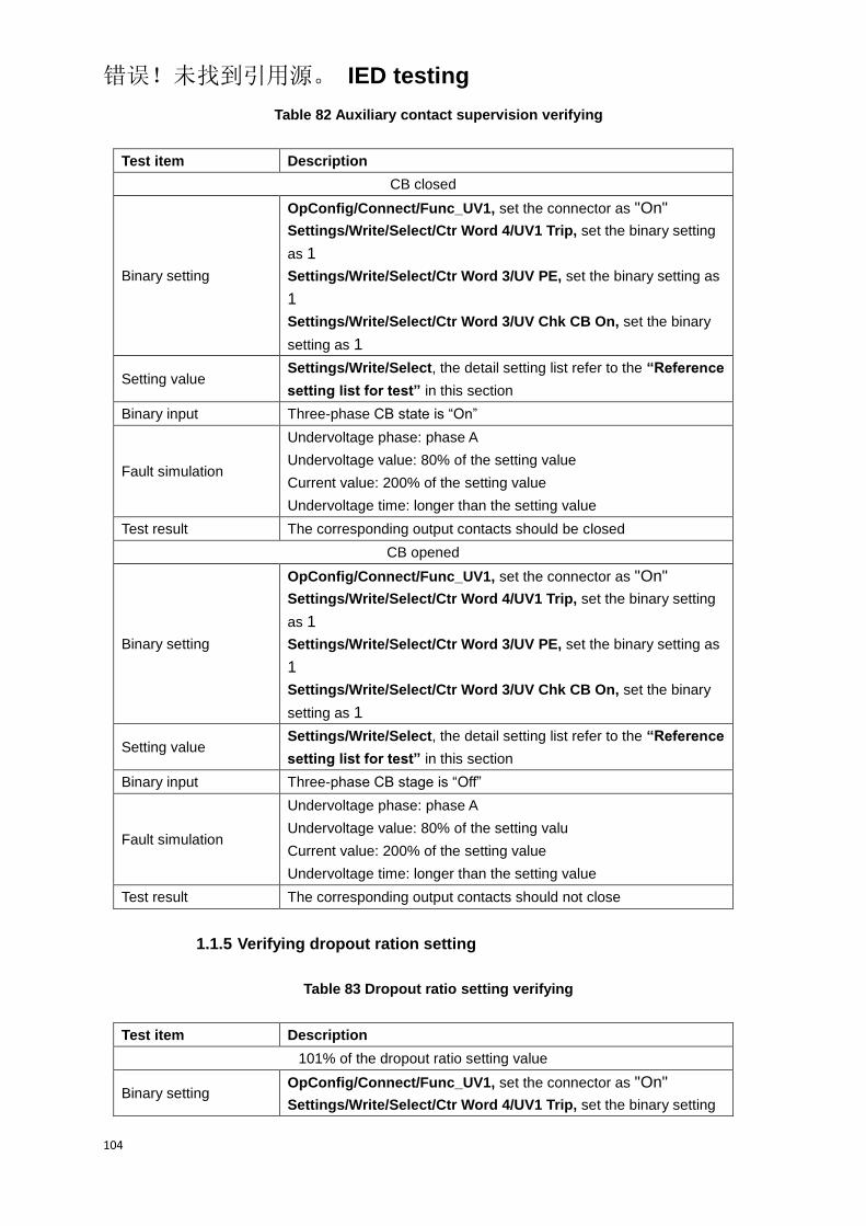
错误!未找到引用源。 IED testing
104
Table 82 Auxiliary contact supervision verifying
Test item Description
CB closed
Binary setting
OpConfig/Connect/Func_UV1, set the connector as "On"
Settings/Write/Select/Ctr Word 4/UV1 Trip, set the binary setting
as 1
Settings/Write/Select/Ctr Word 3/UV PE, set the binary setting as
1
Settings/Write/Select/Ctr Word 3/UV Chk CB On, set the binary
setting as 1
Setting value Settings/Write/Select, the detail setting list refer to the “Reference
setting list for test” in this section
Binary input Three-phase CB state is “On”
Fault simulation
Undervoltage phase: phase A
Undervoltage value: 80% of the setting value
Current value: 200% of the setting value
Undervoltage time: longer than the setting value
Test result The corresponding output contacts should be closed
CB opened
Binary setting
OpConfig/Connect/Func_UV1, set the connector as "On"
Settings/Write/Select/Ctr Word 4/UV1 Trip, set the binary setting
as 1
Settings/Write/Select/Ctr Word 3/UV PE, set the binary setting as
1
Settings/Write/Select/Ctr Word 3/UV Chk CB On, set the binary
setting as 1
Setting value Settings/Write/Select, the detail setting list refer to the “Reference
setting list for test” in this section
Binary input Three-phase CB stage is “Off”
Fault simulation
Undervoltage phase: phase A
Undervoltage value: 80% of the setting valu
Current value: 200% of the setting value
Undervoltage time: longer than the setting value
Test result The corresponding output contacts should not close
1.1.5 Verifying dropout ration setting
Table 83 Dropout ratio setting verifying
Test item Description
101% of the dropout ratio setting value
Binary setting OpConfig/Connect/Func_UV1, set the connector as "On"
Settings/Write/Select/Ctr Word 4/UV1 Trip, set the binary setting
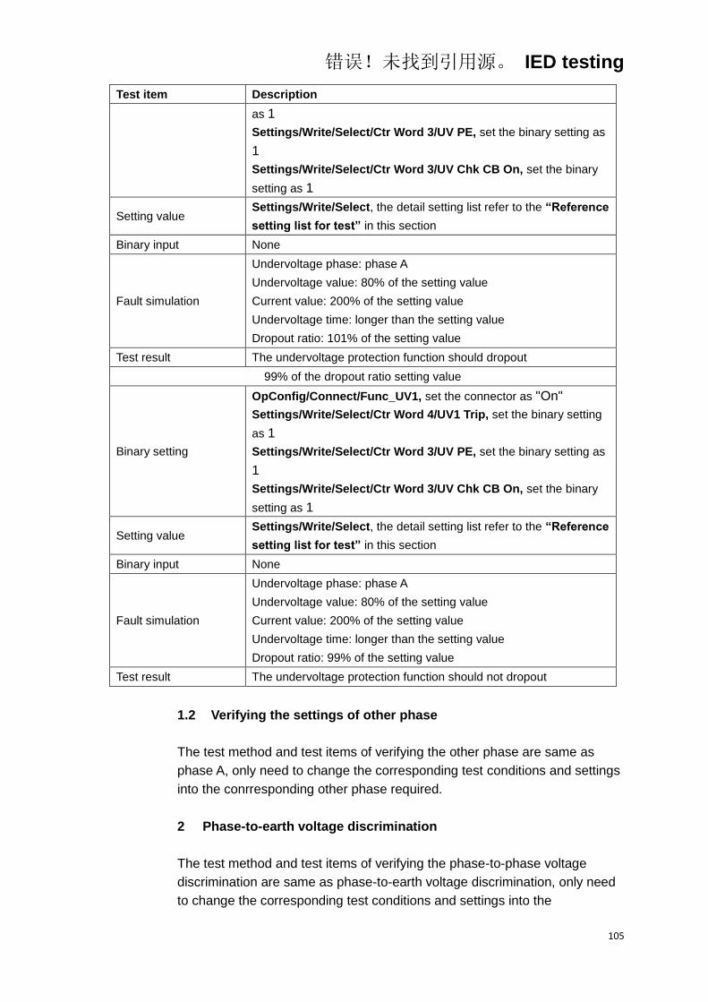
错误!未找到引用源。 IED testing
105
Test item Description
as 1
Settings/Write/Select/Ctr Word 3/UV PE, set the binary setting as
1
Settings/Write/Select/Ctr Word 3/UV Chk CB On, set the binary
setting as 1
Setting value Settings/Write/Select, the detail setting list refer to the “Reference
setting list for test” in this section
Binary input None
Fault simulation
Undervoltage phase: phase A
Undervoltage value: 80% of the setting value
Current value: 200% of the setting value
Undervoltage time: longer than the setting value
Dropout ratio: 101% of the setting value
Test result The undervoltage protection function should dropout
99% of the dropout ratio setting value
Binary setting
OpConfig/Connect/Func_UV1, set the connector as "On"
Settings/Write/Select/Ctr Word 4/UV1 Trip, set the binary setting
as 1
Settings/Write/Select/Ctr Word 3/UV PE, set the binary setting as
1
Settings/Write/Select/Ctr Word 3/UV Chk CB On, set the binary
setting as 1
Setting value Settings/Write/Select, the detail setting list refer to the “Reference
setting list for test” in this section
Binary input None
Fault simulation
Undervoltage phase: phase A
Undervoltage value: 80% of the setting value
Current value: 200% of the setting value
Undervoltage time: longer than the setting value
Dropout ratio: 99% of the setting value
Test result The undervoltage protection function should not dropout
1.2 Verifying the settings of other phase
The test method and test items of verifying the other phase are same as
phase A, only need to change the corresponding test conditions and settings
into the conrresponding other phase required.
2 Phase-to-earth voltage discrimination
The test method and test items of verifying the phase-to-phase voltage
discrimination are same as phase-to-earth voltage discrimination, only need
to change the corresponding test conditions and settings into the

错误!未找到引用源。 IED testing
106
conrresponding phase-to-phase voltage discrimination required.
3 Undervoltage for three phases discrimination
Table 84 Three-phase undervoltage verifying
Test item Description
95% of the voltage setting verifying
Binary setting
OpConfig/Connect/Func_UV1, set the connector as "On"
Settings/Write/Select/Ctr Word 4/UV1 Trip, set the binary setting
as 1
Settings/Write/Select/Ctr Word 3/UV PE, set the binary setting as
1
Settings/Write/Select/Ctr Word 3/UV Chk All Phase, set the
binary setting as 1
Setting value Settings/Write/Select, the detail setting list refer to the “Reference
setting list for test” in this section
Binary input None
Fault simulation
Undervoltage phase: phase A, B, C
Undervoltage value: 95% of the setting value
Current value: 200% of the setting value
Undervoltage time: longer than the setting value
Test result The corresponding output contacts should be closed
105% of the voltage setting verifying
Binary setting
OpConfig/Connect/Func_UV1, set the connector as "On"
Settings/Write/Select/Ctr Word 4/UV1 Trip, set the binary setting
as 1
Settings/Write/Select/Ctr Word 3/UV PE, set the binary setting as
1
Settings/Write/Select/Ctr Word 3/UV Chk All Phase, set the
binary setting as 1
Setting value Settings/Write/Select, the detail setting list refer to the “Reference
setting list for test” in this section
Binary input None
Fault simulation
Undervoltage phase: any one or two or three phase of phase A, B, C
Undervoltage value: 105% of the setting value
Current value: 200% of the setting value
Undervoltage time: longer than the setting value
Test result The corresponding output contacts should not close
8.8.1.2 Verifying the settings of stage 2 of undervoltage protection
The test method and test items of verifying the stage 2 of undervoltage
protection are same as stage 1, only need to change the corresponding test

错误!未找到引用源。 IED testing
107
conditions and settings into the conrresponding stage 1 required.
8.8.2 Completing the test
Continue to test another function or end the test. Restore connections and
settings to their original values, if they were changed for testing purposes.
8.8.3 Reference setting list for test
Table 85 Undervoltage protection connector list
NO. Default Abbr. Explanation
3. On Func_UV1 Enable or disable the stage 1 of undervoltage
protection
4. On Func_UV2 Enable or disable the stage 2 of undervoltage
protection
Table 86 Undervoltage protection function setting list
NO. Default Abbr. Explanation Unit Min. Max.
1. 40 U_UV1 Voltage setting for stage 1 of
undervoltage protection V
5.00
(PE)
10.00
(PP)
75.0
(PE)
150.0
(PP)
2. 0.1 T_UV1 Time setting for stage 1 of
undervoltage protection s 0.00 120.0
3. 40 U_UV2 Voltage setting for stage 2 of
undervoltage protection V
5.00
(PE)
10.00
(PP)
75.0
(PE)
150.0
(PP)
4. 0.1 T_UV2 Time setting for stage 2 of
undervoltage protection s 0.00 120.0
5. 1.05 Dropout_UV Dropout ratio for undervoltage
protection 1.01 2.00
6. 0.2In I_Chk Current setting for
undervoltage protection A 0.00In 2.00In
Table 87 Undervoltage protection binary setting list
Bit Default “0” “1” Explanation
2.9 0 3Ph V Connect 1Ph V Connect Single phase or three phase
voltage connection

错误!未找到引用源。 IED testing
108
Bit Default “0” “1” Explanation
3.0 1 UV Chk CB Off UV Chk CB On Enable or disable the function
of checking CB status
3.1 1 UV Chk All Phase UV Chk One Phase
Enable or disable the function
of checking single phase or
three phase voltage
3.2 1 UV PP UV PE Phase-to-phase or
phase-to-earth discrimination
4.11 1 UV1 Alarm UV1 Trip Stage 1 of undervoltage
protection alarm or trip
8.9 Thermal overload protection
Before starting the test, please make sure that the protection function setting
values and parameters are correct, refer to section Introduction, Points for
attention during testing and Preparing for test in this chapter.
8.9.1 Verifying the settings
8.9.1.1 Verifying the Hot Curve of thermal overload protection
1 Verifying the phase A setting
1.1 Verifying the current setting
Table 88 Current setting verifying
Test item Description
105% of the current setting verifying
Binary setting
OpConfig/Connect/Func_ThermOL, set the connector as "On"
Settings/Write/Select/Ctr Word 2/Hot Curve, set the binary setting
as 1
Setting value Settings/Write/Select, the detail setting list refer to the “Reference
setting list for test” in this section
Binary input None
Fault simulation
Fault type: phase A
Fault current: 105% of the setting value
Fault time: longer than the time calculated by the equation
Test result The corresponding output contacts should be closed
95% of the current setting verifying
Binary setting OpConfig/Connect/Func_ThermOL, set the connector as "On"
Settings/Write/Select/Ctr Word 2/Hot Curve, set the binary setting

错误!未找到引用源。 IED testing
109
Test item Description
as 1
Setting value Settings/Write/Select, the detail setting list refer to the “Reference
setting list for test” in this section
Binary input None
Fault simulation
Fault type: phase A
Fault current: 95% of the setting value
Fault time: longer than the time calculated by the equation
Test result The corresponding output contacts should not close
1.2 Verifying the time setting
Table 89 Time setting verifying
Test item Description
105% of the current setting verifying
Binary setting
OpConfig/Connect/Func_ThermOL, set the connector as "On"
Settings/Write/Select/Ctr Word 2/Hot Curve, set the binary setting
as 1
Setting value Settings/Write/Select, the detail setting list refer to the “Reference
setting list for test” in this section
Binary input None
Fault simulation
Fault type: phase A
Fault current: 200% of the setting value
Fault time: longer than the time calculated by the equation
Test result The corresponding output contacts should be closed, and the
operate time meet the requirement in technical data
1.3 Verifying the cool ratio setting
Table 90 Cool ratio setting verifying
Test item Description
105% of the current setting verifying
Binary setting
OpConfig/Connect/Func_ThermOL, set the connector as "On"
Settings/Write/Select/Ctr Word 2/Hot Curve, set the binary setting
as 1
Setting value Settings/Write/Select, the detail setting list refer to the “Reference
setting list for test” in this section
Binary input None
Fault simulation
First thermal accumulation phase:
Fault type: phase A
Fault current: 80% of the setting value
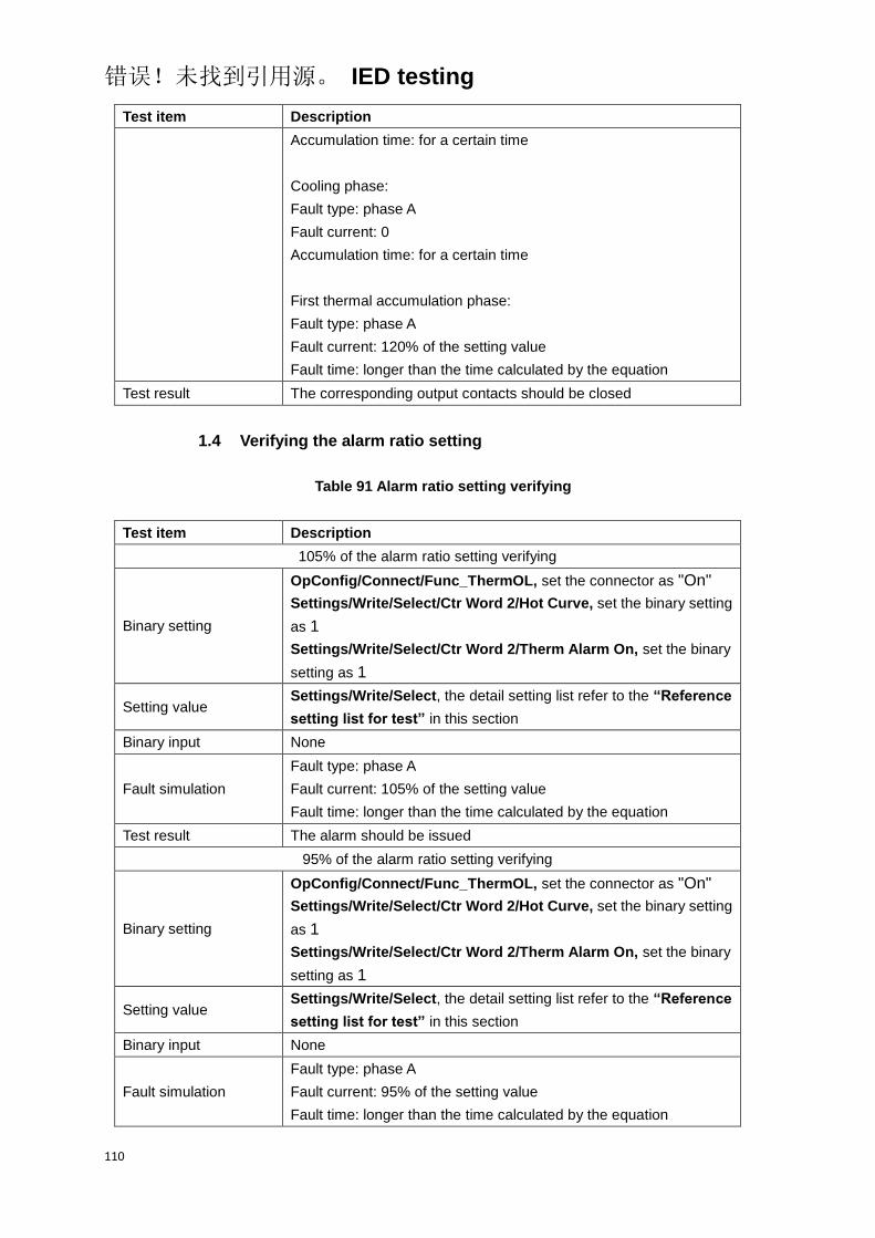
错误!未找到引用源。 IED testing
110
Test item Description
Accumulation time: for a certain time
Cooling phase:
Fault type: phase A
Fault current: 0
Accumulation time: for a certain time
First thermal accumulation phase:
Fault type: phase A
Fault current: 120% of the setting value
Fault time: longer than the time calculated by the equation
Test result The corresponding output contacts should be closed
1.4 Verifying the alarm ratio setting
Table 91 Alarm ratio setting verifying
Test item Description
105% of the alarm ratio setting verifying
Binary setting
OpConfig/Connect/Func_ThermOL, set the connector as "On"
Settings/Write/Select/Ctr Word 2/Hot Curve, set the binary setting
as 1
Settings/Write/Select/Ctr Word 2/Therm Alarm On, set the binary
setting as 1
Setting value Settings/Write/Select, the detail setting list refer to the “Reference
setting list for test” in this section
Binary input None
Fault simulation
Fault type: phase A
Fault current: 105% of the setting value
Fault time: longer than the time calculated by the equation
Test result The alarm should be issued
95% of the alarm ratio setting verifying
Binary setting
OpConfig/Connect/Func_ThermOL, set the connector as "On"
Settings/Write/Select/Ctr Word 2/Hot Curve, set the binary setting
as 1
Settings/Write/Select/Ctr Word 2/Therm Alarm On, set the binary
setting as 1
Setting value Settings/Write/Select, the detail setting list refer to the “Reference
setting list for test” in this section
Binary input None
Fault simulation
Fault type: phase A
Fault current: 95% of the setting value
Fault time: longer than the time calculated by the equation
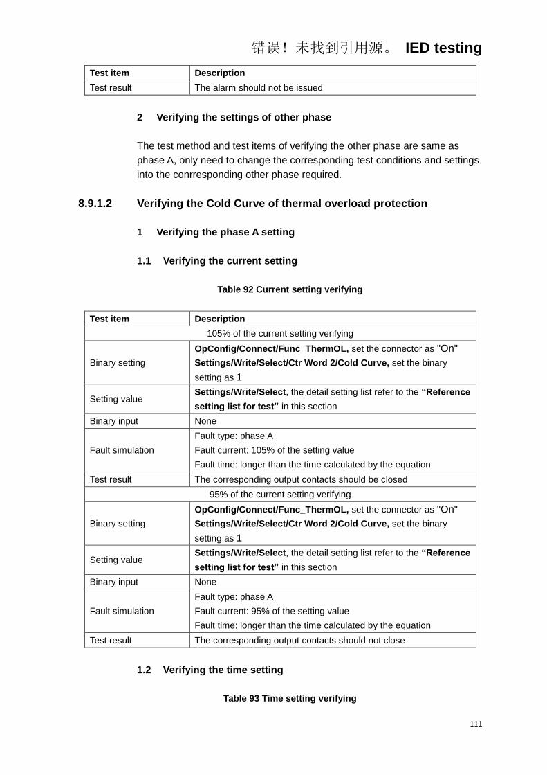
错误!未找到引用源。 IED testing
111
Test item Description
Test result The alarm should not be issued
2 Verifying the settings of other phase
The test method and test items of verifying the other phase are same as
phase A, only need to change the corresponding test conditions and settings
into the conrresponding other phase required.
8.9.1.2 Verifying the Cold Curve of thermal overload protection
1 Verifying the phase A setting
1.1 Verifying the current setting
Table 92 Current setting verifying
Test item Description
105% of the current setting verifying
Binary setting
OpConfig/Connect/Func_ThermOL, set the connector as "On"
Settings/Write/Select/Ctr Word 2/Cold Curve, set the binary
setting as 1
Setting value Settings/Write/Select, the detail setting list refer to the “Reference
setting list for test” in this section
Binary input None
Fault simulation
Fault type: phase A
Fault current: 105% of the setting value
Fault time: longer than the time calculated by the equation
Test result The corresponding output contacts should be closed
95% of the current setting verifying
Binary setting
OpConfig/Connect/Func_ThermOL, set the connector as "On"
Settings/Write/Select/Ctr Word 2/Cold Curve, set the binary
setting as 1
Setting value Settings/Write/Select, the detail setting list refer to the “Reference
setting list for test” in this section
Binary input None
Fault simulation
Fault type: phase A
Fault current: 95% of the setting value
Fault time: longer than the time calculated by the equation
Test result The corresponding output contacts should not close
1.2 Verifying the time setting
Table 93 Time setting verifying

错误!未找到引用源。 IED testing
112
Test item Description
105% of the current setting verifying
Binary setting
OpConfig/Connect/Func_ThermOL, set the connector as "On"
Settings/Write/Select/Ctr Word 2/Cold Curve, set the binary
setting as 1
Setting value Settings/Write/Select, the detail setting list refer to the “Reference
setting list for test” in this section
Binary input None
Fault simulation
Fault type: phase A
Fault current: 200% of the setting value
Fault time: longer than the time calculated by the equation
Test result The corresponding output contacts should be closed, and the
operate time meet the requirement in technical data
1.3 Verifying the alarm ratio setting
Table 94 Alarm ratio setting verifying
Test item Description
105% of the alarm ratio setting verifying
Binary setting
OpConfig/Connect/Func_ThermOL, set the connector as "On"
Settings/Write/Select/Ctr Word 2/Cold Curve, set the binary
setting as 1
Settings/Write/Select/Ctr Word 2/Therm Alarm On, set the binary
setting as 1
Setting value Settings/Write/Select, the detail setting list refer to the “Reference
setting list for test” in this section
Binary input None
Fault simulation
Fault type: phase A
Fault current: 105% of the setting value
Fault time: longer than the time calculated by the equation
Test result The alarm should be issued
95% of the alarm ratio setting verifying
Binary setting
OpConfig/Connect/Func_ThermOL, set the connector as "On"
Settings/Write/Select/Ctr Word 2/Cold Curve, set the binary
setting as 1
Settings/Write/Select/Ctr Word 2/Therm Alarm On, set the binary
setting as 1
Setting value Settings/Write/Select, the detail setting list refer to the “Reference
setting list for test” in this section
Binary input None
Fault simulation
Fault type: phase A
Fault current: 95% of the setting value
Fault time: longer than the time calculated by the equation
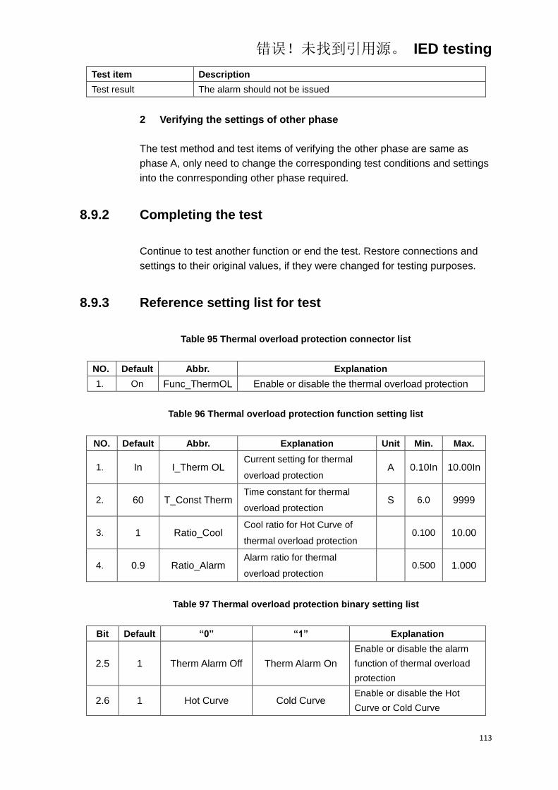
错误!未找到引用源。 IED testing
113
Test item Description
Test result The alarm should not be issued
2 Verifying the settings of other phase
The test method and test items of verifying the other phase are same as
phase A, only need to change the corresponding test conditions and settings
into the conrresponding other phase required.
8.9.2 Completing the test
Continue to test another function or end the test. Restore connections and
settings to their original values, if they were changed for testing purposes.
8.9.3 Reference setting list for test
Table 95 Thermal overload protection connector list
NO. Default Abbr. Explanation
1. On Func_ThermOL Enable or disable the thermal overload protection
Table 96 Thermal overload protection function setting list
NO. Default Abbr. Explanation Unit Min. Max.
1. In I_Therm OL Current setting for thermal
overload protection A 0.10In 10.00In
2. 60 T_Const Therm Time constant for thermal
overload protection S 6.0 9999
3. 1 Ratio_Cool Cool ratio for Hot Curve of
thermal overload protection
0.100 10.00
4. 0.9 Ratio_Alarm Alarm ratio for thermal
overload protection
0.500 1.000
Table 97 Thermal overload protection binary setting list
Bit Default “0” “1” Explanation
2.5 1 Therm Alarm Off Therm Alarm On
Enable or disable the alarm
function of thermal overload
protection
2.6 1 Hot Curve Cold Curve Enable or disable the Hot
Curve or Cold Curve

错误!未找到引用源。 IED testing
114
8.10 Displacement voltage protection
Before starting the test, please make sure that the protection function setting
values and parameters are correct, refer to section Introduction, Points for
attention during testing and Preparing for test in this chapter.
8.10.1 Verifying the settings
8.10.1.1 Verifying the settings of stage 1 of displacement voltage
protection
1 Verifying the phase A settings
1.1 Verifying the voltage setting
Table 98 Voltage setting verifying
Test item Description
105% of the voltage setting verifying
Binary setting
OpConfig/Connect/Func_3V01, set the connector as "On"
Settings/Write/Select/Ctr Word 4/3V01 Trip, set the binary setting
as 1
Settings/Write/Select/Ctr Word 2/3U0 calculated, set the binary
setting as 1
Setting value Settings/Write/Select, the detail setting list refer to the “Reference
setting list for test” in this section
Binary input None
Fault simulation
Precondition: three phase-ground voltages connected to IED in
grounded wye configuration
Displacement voltage phase: phase A
Displacement voltage value: 105% of the setting value
Displacement voltage time: longer than the setting value
Test result The corresponding output contacts should be closed
95% of the voltage setting verifying
Binary setting
OpConfig/Connect/Func_3V01, set the connector as "On"
Settings/Write/Select/Ctr Word 4/3V01 Trip, set the binary setting
as 1
Settings/Write/Select/Ctr Word 2/3U0 calculated, set the binary
setting as 1
Setting value Settings/Write/Select, the detail setting list refer to the “Reference
setting list for test” in this section
Binary input None

错误!未找到引用源。 IED testing
115
Test item Description
Fault simulation
Precondition: three phase-ground voltages connected to IED in
grounded wye configuration
Displacement voltage phase: phase A
Displacement voltage value: 95% of the setting value
Displacement voltage time: longer than the setting value
Test result The corresponding output contacts should not close
1.2 Veritying the time setting
Table 99 Time setting verifying
Test item Description
Binary setting
OpConfig/Connect/Func_3V01, set the connector as "On"
Settings/Write/Select/Ctr Word 4/3V01 Trip, set the binary setting
as 1
Settings/Write/Select/Ctr Word 2/3U0 calculated, set the binary
setting as 1
Setting value Settings/Write/Select, the detail setting list refer to the “Reference
setting list for test” in this section
Binary input None
Fault simulation
Precondition: three phase-ground voltages connected to IED in
grounded wye configuration
Displacement voltage phase: phase A
Displacement voltage value: 120% of the setting value
Displacement voltage time: longer than the setting value
Test result The corresponding output contacts should be closed, and the
operate time meet the requirement in technical data
2 Verifying the settings of other phase
The test method and test items of verifying the other phase are same as
phase A, only need to change the corresponding test conditions and settings
into the conrresponding other phase required.
8.10.1.2 Verifying the settings of stage 2 of overvoltage protection
The test method and test items of verifying the stage 2 of overvoltage
protection are same as stage 1, only need to change the corresponding test
conditions and settings into the conrresponding stage 2 required.
8.10.1.3 Verifying the settings for determining the fault phase
1 Verifying the phase A settings
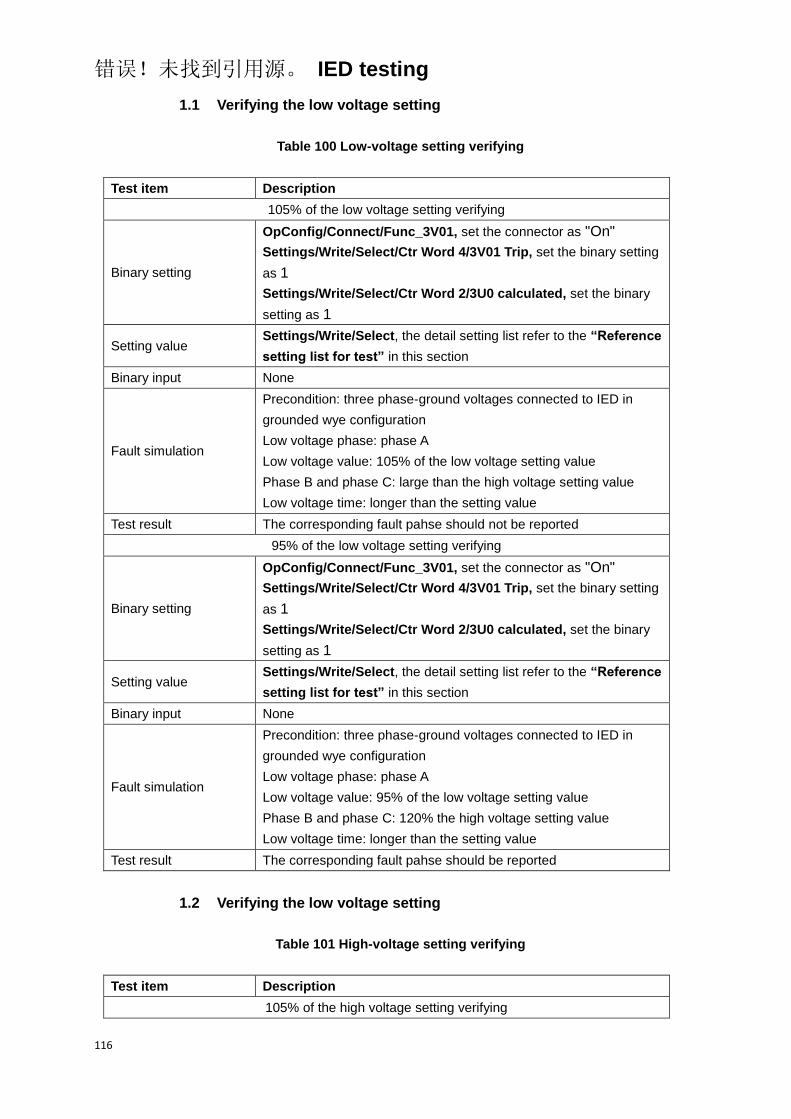
错误!未找到引用源。 IED testing
116
1.1 Verifying the low voltage setting
Table 100 Low-voltage setting verifying
Test item Description
105% of the low voltage setting verifying
Binary setting
OpConfig/Connect/Func_3V01, set the connector as "On"
Settings/Write/Select/Ctr Word 4/3V01 Trip, set the binary setting
as 1
Settings/Write/Select/Ctr Word 2/3U0 calculated, set the binary
setting as 1
Setting value Settings/Write/Select, the detail setting list refer to the “Reference
setting list for test” in this section
Binary input None
Fault simulation
Precondition: three phase-ground voltages connected to IED in
grounded wye configuration
Low voltage phase: phase A
Low voltage value: 105% of the low voltage setting value
Phase B and phase C: large than the high voltage setting value
Low voltage time: longer than the setting value
Test result The corresponding fault pahse should not be reported
95% of the low voltage setting verifying
Binary setting
OpConfig/Connect/Func_3V01, set the connector as "On"
Settings/Write/Select/Ctr Word 4/3V01 Trip, set the binary setting
as 1
Settings/Write/Select/Ctr Word 2/3U0 calculated, set the binary
setting as 1
Setting value Settings/Write/Select, the detail setting list refer to the “Reference
setting list for test” in this section
Binary input None
Fault simulation
Precondition: three phase-ground voltages connected to IED in
grounded wye configuration
Low voltage phase: phase A
Low voltage value: 95% of the low voltage setting value
Phase B and phase C: 120% the high voltage setting value
Low voltage time: longer than the setting value
Test result The corresponding fault pahse should be reported
1.2 Verifying the low voltage setting
Table 101 High-voltage setting verifying
Test item Description
105% of the high voltage setting verifying
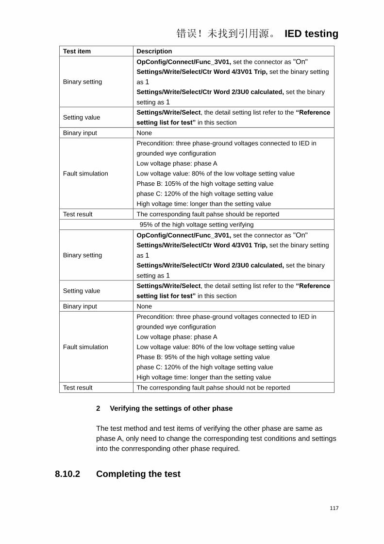
错误!未找到引用源。 IED testing
117
Test item Description
Binary setting
OpConfig/Connect/Func_3V01, set the connector as "On"
Settings/Write/Select/Ctr Word 4/3V01 Trip, set the binary setting
as 1
Settings/Write/Select/Ctr Word 2/3U0 calculated, set the binary
setting as 1
Setting value Settings/Write/Select, the detail setting list refer to the “Reference
setting list for test” in this section
Binary input None
Fault simulation
Precondition: three phase-ground voltages connected to IED in
grounded wye configuration
Low voltage phase: phase A
Low voltage value: 80% of the low voltage setting value
Phase B: 105% of the high voltage setting value
phase C: 120% of the high voltage setting value
High voltage time: longer than the setting value
Test result The corresponding fault pahse should be reported
95% of the high voltage setting verifying
Binary setting
OpConfig/Connect/Func_3V01, set the connector as "On"
Settings/Write/Select/Ctr Word 4/3V01 Trip, set the binary setting
as 1
Settings/Write/Select/Ctr Word 2/3U0 calculated, set the binary
setting as 1
Setting value Settings/Write/Select, the detail setting list refer to the “Reference
setting list for test” in this section
Binary input None
Fault simulation
Precondition: three phase-ground voltages connected to IED in
grounded wye configuration
Low voltage phase: phase A
Low voltage value: 80% of the low voltage setting value
Phase B: 95% of the high voltage setting value
phase C: 120% of the high voltage setting value
High voltage time: longer than the setting value
Test result The corresponding fault pahse should not be reported
2 Verifying the settings of other phase
The test method and test items of verifying the other phase are same as
phase A, only need to change the corresponding test conditions and settings
into the conrresponding other phase required.
8.10.2 Completing the test
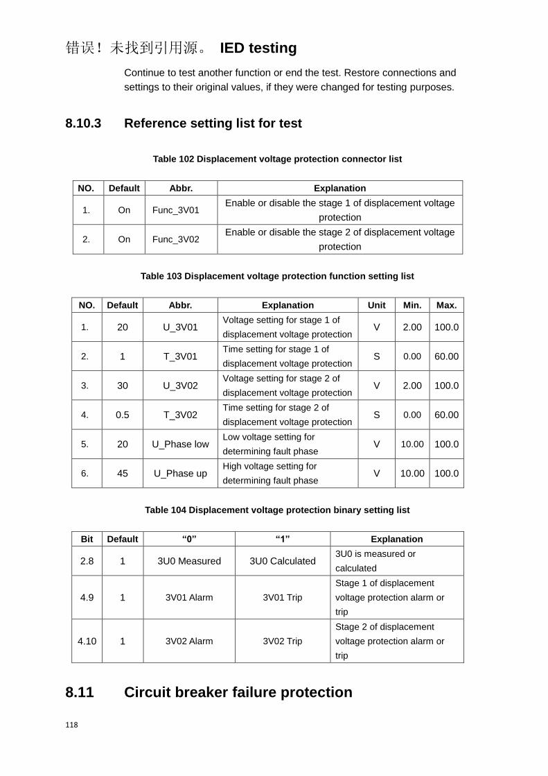
错误!未找到引用源。 IED testing
118
Continue to test another function or end the test. Restore connections and
settings to their original values, if they were changed for testing purposes.
8.10.3 Reference setting list for test
Table 102 Displacement voltage protection connector list
NO. Default Abbr. Explanation
1. On Func_3V01 Enable or disable the stage 1 of displacement voltage
protection
2. On Func_3V02 Enable or disable the stage 2 of displacement voltage
protection
Table 103 Displacement voltage protection function setting list
NO. Default Abbr. Explanation Unit Min. Max.
1. 20 U_3V01 Voltage setting for stage 1 of
displacement voltage protection V 2.00 100.0
2. 1 T_3V01 Time setting for stage 1 of
displacement voltage protection S 0.00 60.00
3. 30 U_3V02 Voltage setting for stage 2 of
displacement voltage protection V 2.00 100.0
4. 0.5 T_3V02 Time setting for stage 2 of
displacement voltage protection S 0.00 60.00
5. 20 U_Phase low Low voltage setting for
determining fault phase V 10.00 100.0
6. 45 U_Phase up High voltage setting for
determining fault phase V 10.00 100.0
Table 104 Displacement voltage protection binary setting list
Bit Default “0” “1” Explanation
2.8 1 3U0 Measured 3U0 Calculated 3U0 is measured or
calculated
4.9 1 3V01 Alarm 3V01 Trip
Stage 1 of displacement
voltage protection alarm or
trip
4.10 1 3V02 Alarm 3V02 Trip
Stage 2 of displacement
voltage protection alarm or
trip
8.11 Circuit breaker failure protection
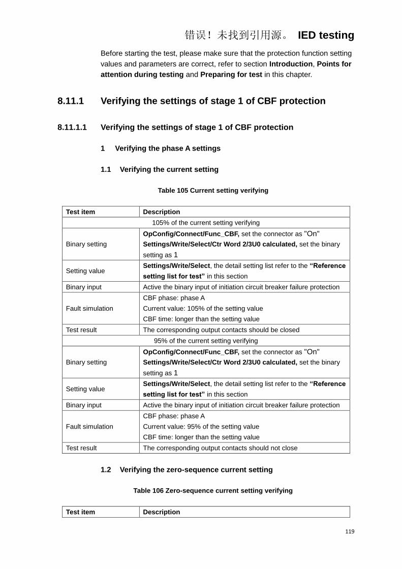
错误!未找到引用源。 IED testing
119
Before starting the test, please make sure that the protection function setting
values and parameters are correct, refer to section Introduction, Points for
attention during testing and Preparing for test in this chapter.
8.11.1 Verifying the settings of stage 1 of CBF protection
8.11.1.1 Verifying the settings of stage 1 of CBF protection
1 Verifying the phase A settings
1.1 Verifying the current setting
Table 105 Current setting verifying
Test item Description
105% of the current setting verifying
Binary setting
OpConfig/Connect/Func_CBF, set the connector as "On"
Settings/Write/Select/Ctr Word 2/3U0 calculated, set the binary
setting as 1
Setting value Settings/Write/Select, the detail setting list refer to the “Reference
setting list for test” in this section
Binary input Active the binary input of initiation circuit breaker failure protection
Fault simulation
CBF phase: phase A
Current value: 105% of the setting value
CBF time: longer than the setting value
Test result The corresponding output contacts should be closed
95% of the current setting verifying
Binary setting
OpConfig/Connect/Func_CBF, set the connector as "On"
Settings/Write/Select/Ctr Word 2/3U0 calculated, set the binary
setting as 1
Setting value Settings/Write/Select, the detail setting list refer to the “Reference
setting list for test” in this section
Binary input Active the binary input of initiation circuit breaker failure protection
Fault simulation
CBF phase: phase A
Current value: 95% of the setting value
CBF time: longer than the setting value
Test result The corresponding output contacts should not close
1.2 Verifying the zero-sequence current setting
Table 106 Zero-sequence current setting verifying
Test item Description
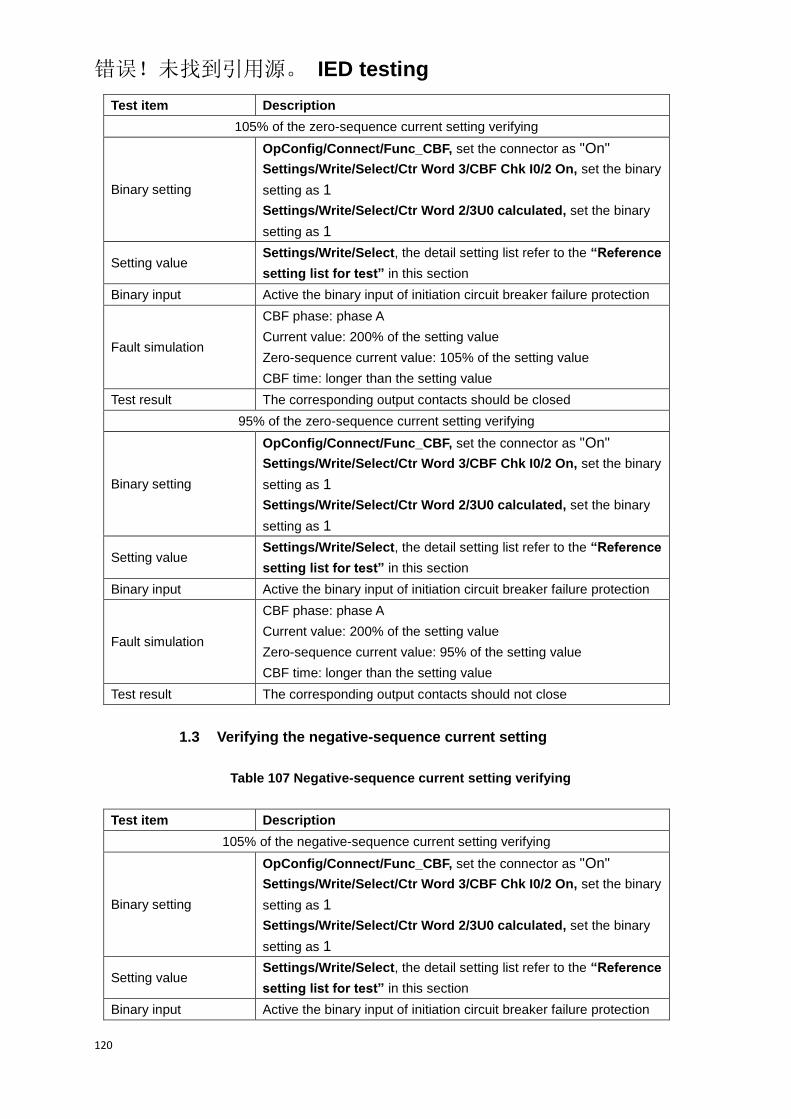
错误!未找到引用源。 IED testing
120
Test item Description
105% of the zero-sequence current setting verifying
Binary setting
OpConfig/Connect/Func_CBF, set the connector as "On"
Settings/Write/Select/Ctr Word 3/CBF Chk I0/2 On, set the binary
setting as 1
Settings/Write/Select/Ctr Word 2/3U0 calculated, set the binary
setting as 1
Setting value Settings/Write/Select, the detail setting list refer to the “Reference
setting list for test” in this section
Binary input Active the binary input of initiation circuit breaker failure protection
Fault simulation
CBF phase: phase A
Current value: 200% of the setting value
Zero-sequence current value: 105% of the setting value
CBF time: longer than the setting value
Test result The corresponding output contacts should be closed
95% of the zero-sequence current setting verifying
Binary setting
OpConfig/Connect/Func_CBF, set the connector as "On"
Settings/Write/Select/Ctr Word 3/CBF Chk I0/2 On, set the binary
setting as 1
Settings/Write/Select/Ctr Word 2/3U0 calculated, set the binary
setting as 1
Setting value Settings/Write/Select, the detail setting list refer to the “Reference
setting list for test” in this section
Binary input Active the binary input of initiation circuit breaker failure protection
Fault simulation
CBF phase: phase A
Current value: 200% of the setting value
Zero-sequence current value: 95% of the setting value
CBF time: longer than the setting value
Test result The corresponding output contacts should not close
1.3 Verifying the negative-sequence current setting
Table 107 Negative-sequence current setting verifying
Test item Description
105% of the negative-sequence current setting verifying
Binary setting
OpConfig/Connect/Func_CBF, set the connector as "On"
Settings/Write/Select/Ctr Word 3/CBF Chk I0/2 On, set the binary
setting as 1
Settings/Write/Select/Ctr Word 2/3U0 calculated, set the binary
setting as 1
Setting value Settings/Write/Select, the detail setting list refer to the “Reference
setting list for test” in this section
Binary input Active the binary input of initiation circuit breaker failure protection

错误!未找到引用源。 IED testing
121
Test item Description
Fault simulation
CBF phase: phase A
Current value: 200% of the setting value
Negative-sequence current value: 105% of the setting value
CBF time: longer than the setting value
Test result The corresponding output contacts should be closed
95% of the negative-sequence current setting verifying
Binary setting
OpConfig/Connect/Func_CBF, set the connector as "On"
Settings/Write/Select/Ctr Word 3/CBF Chk I0/2 On, set the binary
setting as 1
Settings/Write/Select/Ctr Word 2/3U0 calculated, set the binary
setting as 1
Setting value Settings/Write/Select, the detail setting list refer to the “Reference
setting list for test” in this section
Binary input Active the binary input of initiation circuit breaker failure protection
Fault simulation
CBF phase: phase A
Current value: 200% of the setting value
Negative-sequence current value: 95% of the setting value
CBF time: longer than the setting value
Test result The corresponding output contacts should not close
1.4 Verifying the CB status
Table 108 CB status verifying
Test item Description
The CB status is “On”
Binary setting
OpConfig/Connect/Func_CBF, set the connector as "On"
Settings/Write/Select/Ctr Word 3/CBF Chk CB On, set the binary
setting as 1
Settings/Write/Select/Ctr Word 2/3U0 calculated, set the binary
setting as 1
Setting value Settings/Write/Select, the detail setting list refer to the “Reference
setting list for test” in this section
Binary input Active the binary input of initiation circuit breaker failure protection
The CB status is “On”
Fault simulation
CBF phase: phase A
Current value: 70% of the setting value
CBF time: longer than the setting value
Test result The corresponding output contacts should be closed
The CB status is “Off”
Binary setting
OpConfig/Connect/Func_CBF, set the connector as "On"
Settings/Write/Select/Ctr Word 3/CBF Chk CB On, set the binary
setting as 1

错误!未找到引用源。 IED testing
122
Test item Description
Settings/Write/Select/Ctr Word 2/3U0 calculated, set the binary
setting as 1
Setting value Settings/Write/Select, the detail setting list refer to the “Reference
setting list for test” in this section
Binary input Active the binary input of initiation circuit breaker failure protection
The CB status is “Off”
Fault simulation
CBF phase: phase A
Current value: 70% of the setting value
CBF time: longer than the setting value
Test result The corresponding output contacts should not close
1.5 Verifying the time setting
Table 109 Time setting verifying
Test item Description
Binary setting
OpConfig/Connect/Func_CBF, set the connector as "On"
Settings/Write/Select/Ctr Word 2/3U0 calculated, set the binary
setting as 1
Setting value Settings/Write/Select, the detail setting list refer to the “Reference
setting list for test” in this section
Binary input Active the binary input of initiation circuit breaker failure protection
Fault simulation
CBF phase: phase A
Current value: 200% of the setting value
CBF time: longer than the setting value
Test result The corresponding output contacts should be closed, and the
operate time meet the requirement in technical data
2 Verifying the settings of other phase
The test method and test items of verifying the settings of other phase
protection are same as phase A, only need to change the corresponding test
conditions and settings into the conrresponding phase A required.
8.11.1.2 Verifying the settings of stage 2 of CBF protection
The test method and test items of verifying the stage 2 of CBF protection are
same as stage 1, only need to change the corresponding test conditions and
settings into the conrresponding stage 2 required.
8.11.2 Completing the test

错误!未找到引用源。 IED testing
123
Continue to test another function or end the test. Restore connections and
settings to their original values, if they were changed for testing purposes.
8.11.3 Reference setting list for test
Table 110 CBF protection connector list
NO. Default Abbr. Explanation
1. On Func_CBF Enable or disable the circuit breaker failure protection
Table 111 CBF protection function setting list
NO. Default Abbr. Explanation Unit Min. Max.
1. In I_CBF Phase current setting for CBF
protection A 0.05In 20.00In
2. In 3I0_CBF Zero-sequence current setting
for CBF protection A 0.05In 20.00In
3. In 3I2_CBF Negative-sequence current
setting for CBF protection A 0.05In 20.00In
4. 0 T_CBF1 Delay time for stage 1 of CBF
protection s 0.00 60.00
5. 0.2 T_CBF2 Delay time for stage 2 of CBF
protection s 0.10 60.00
Table 112 CBF protection binary setting list
Bit Default “0” “1” Explanation
2.7 1 3I0 Measured 3I0 Calculated 3U0 is measured or
calculated
3.6 1 CBF Chk I0/2 Off CBF Chk I0/2 On
Enable or disable the function
for checking zero or negative
sequence current
3.7 1 CBF Chk CB Off CBF Chk CB On Enable or disable the function
for checking CB status
8.12 Dead zone protection
Before starting the test, please make sure that the protection function setting
values and parameters are correct, refer to section Introduction, Points for
attention during testing and Preparing for test in this chapter.

错误!未找到引用源。 IED testing
124
8.12.1 Verifying the settings
1 Verifying the phase A setting
1.1 Verifying the current setting
Table 113 Current setting verifying
Test item Description
105% of the current setting verifying
Binary setting OpConfig/Connect/Func_DZ, set the connector as "On"
Setting value Settings/Write/Select, the detail setting list refer to the “Reference
setting list for test” in this section
Binary input Three phase CB status is “Off”
Active the binary input of initiation circuit breaker failure protection
Fault simulation
Fault type: phase A, instantanuous
Fault current: 105% of the setting value
Fault time: longer than the setting value
Test result The corresponding output contacts should be closed
95% of the current setting verifying
Binary setting OpConfig/Connect/Func_DZ, set the connector as "On"
Setting value Settings/Write/Select, the detail setting list refer to the “Reference
setting list for test” in this section
Binary input Three phase CB status is “Off”
Active the binary input of initiation circuit breaker failure protection
Fault simulation
Fault type: phase A, instantanuous
Fault current: 95% of the setting value
Fault time: longer than the setting value
Test result The corresponding output contacts should not close
1.2 Verifying the time setting
Table 114 Time setting verifying
Test item Description
Binary setting OpConfig/Connect/Func_DZ, set the connector as "On"
Setting value Settings/Write/Select, the detail setting list refer to the “Reference
setting list for test” in this section
Binary input Three phase CB status is “Off”
Active the binary input of initiation circuit breaker failure protection
Fault simulation
Fault type: phase A, instantanuous
Fault current: 200% of the setting value
Fault time: longer than the setting value

错误!未找到引用源。 IED testing
125
Test item Description
Test result The corresponding output contacts should be closed, and the
operated time meet the requirement in technical data
2 Verifying the settings of other phase
The test method and test items of verifying the other phase are same as
phase A, only need to change the corresponding test conditions and settings
into the conrresponding other phase required.
8.12.2 Completing the test
Continue to test another function or end the test. Restore connections and
settings to their original values, if they were changed for testing purposes.
8.12.3 Reference setting list for test
Table 115 Dead zone protection connector list
NO. Default Abbr. Explanation
1. On Func_DZ Enable or disable the dead zone protection
Table 116 Dead zone protection function setting list
NO. Default Abbr. Explanation Unit Min. Max.
1. 0.2 T_Dead Zone Time delay for dead zone
protection s 0.00 60
2. In I_CBF Phase current setting for CBF
protection A 0.05In 20In
8.13 Synchro-check and energizing check function
Before starting the test, please make sure that the protection function setting
values and parameters are correct, refer to section Introduction, Points for
attention during testing and Preparing for test in this chapter.
8.13.1 Verifying the settings

错误!未找到引用源。 IED testing
126
UA
UB
UC
UN
U4
UA
UB
UC
UN
U4
Tester IED
Figure 13 Connection example of synchro-check function
If the tester can't provide the reference voltage U4, the wiring connection is
shown in Figure 14.
UA
UB
UC
UN
UA
UB
UC
UN
U4
Tester IED
Figure 14 Connection example of synchro-check function
8.13.1.1 Synchro-check function
1 Verifying the phase A of synchro-check
1.1 Verifying the voltage difference
Table 117 Voltage difference setting verifying
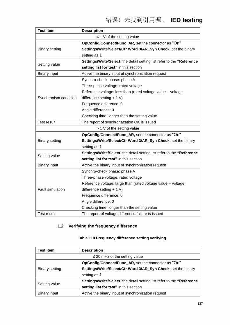
错误!未找到引用源。 IED testing
127
Test item Description
≤ 1 V of the setting value
Binary setting
OpConfig/Connect/Func_AR, set the connector as "On"
Settings/Write/Select/Ctr Word 3/AR_Syn Check, set the binary
setting as 1
Setting value Settings/Write/Select, the detail setting list refer to the “Reference
setting list for test” in this section
Binary input Active the binary input of synchronization request
Synchronism condition
Synchro-check phase: phase A
Three-phase voltage: rated voltage
Reference voltage: less than (rated voltage value – voltage
difference setting + 1 V)
Frequence difference: 0
Angle difference: 0
Checking time: longer than the setting value
Test result The report of synchronazation OK is issued
> 1 V of the setting value
Binary setting
OpConfig/Connect/Func_AR, set the connector as "On"
Settings/Write/Select/Ctr Word 3/AR_Syn Check, set the binary
setting as 1
Setting value Settings/Write/Select, the detail setting list refer to the “Reference
setting list for test” in this section
Binary input Active the binary input of synchronization request
Fault simulation
Synchro-check phase: phase A
Three-phase voltage: rated voltage
Reference voltage: large than (rated voltage value – voltage
difference setting + 1 V)
Frequence difference: 0
Angle difference: 0
Checking time: longer than the setting value
Test result The report of voltage difference failure is issued
1.2 Verifying the frequency difference
Table 118 Frequency difference setting verifying
Test item Description
≤ 20 mHz of the setting value
Binary setting
OpConfig/Connect/Func_AR, set the connector as "On"
Settings/Write/Select/Ctr Word 3/AR_Syn Check, set the binary
setting as 1
Setting value Settings/Write/Select, the detail setting list refer to the “Reference
setting list for test” in this section
Binary input Active the binary input of synchronization request
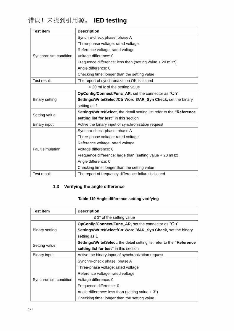
错误!未找到引用源。 IED testing
128
Test item Description
Synchronism condition
Synchro-check phase: phase A
Three-phase voltage: rated voltage
Reference voltage: rated voltage
Voltage difference: 0
Frequence difference: less than (setting value + 20 mHz)
Angle difference: 0
Checking time: longer than the setting value
Test result The report of synchronazation OK is issued
> 20 mHz of the setting value
Binary setting
OpConfig/Connect/Func_AR, set the connector as "On"
Settings/Write/Select/Ctr Word 3/AR_Syn Check, set the binary
setting as 1
Setting value Settings/Write/Select, the detail setting list refer to the “Reference
setting list for test” in this section
Binary input Active the binary input of synchronization request
Fault simulation
Synchro-check phase: phase A
Three-phase voltage: rated voltage
Reference voltage: rated voltage
Voltage difference: 0
Frequence difference: large than (setting value + 20 mHz)
Angle difference: 0
Checking time: longer than the setting value
Test result The report of frequency difference failure is issued
1.3 Verifying the angle difference
Table 119 Angle difference setting verifying
Test item Description
≤ 3° of the setting value
Binary setting
OpConfig/Connect/Func_AR, set the connector as "On"
Settings/Write/Select/Ctr Word 3/AR_Syn Check, set the binary
setting as 1
Setting value Settings/Write/Select, the detail setting list refer to the “Reference
setting list for test” in this section
Binary input Active the binary input of synchronization request
Synchronism condition
Synchro-check phase: phase A
Three-phase voltage: rated voltage
Reference voltage: rated voltage
Voltage difference: 0
Frequence difference: 0
Angle difference: less than (setting value + 3°)
Checking time: longer than the setting value
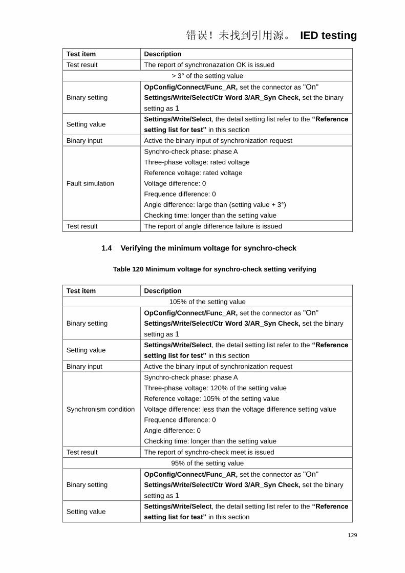
错误!未找到引用源。 IED testing
129
Test item Description
Test result The report of synchronazation OK is issued
> 3° of the setting value
Binary setting
OpConfig/Connect/Func_AR, set the connector as "On"
Settings/Write/Select/Ctr Word 3/AR_Syn Check, set the binary
setting as 1
Setting value Settings/Write/Select, the detail setting list refer to the “Reference
setting list for test” in this section
Binary input Active the binary input of synchronization request
Fault simulation
Synchro-check phase: phase A
Three-phase voltage: rated voltage
Reference voltage: rated voltage
Voltage difference: 0
Frequence difference: 0
Angle difference: large than (setting value + 3°)
Checking time: longer than the setting value
Test result The report of angle difference failure is issued
1.4 Verifying the minimum voltage for synchro-check
Table 120 Minimum voltage for synchro-check setting verifying
Test item Description
105% of the setting value
Binary setting
OpConfig/Connect/Func_AR, set the connector as "On"
Settings/Write/Select/Ctr Word 3/AR_Syn Check, set the binary
setting as 1
Setting value Settings/Write/Select, the detail setting list refer to the “Reference
setting list for test” in this section
Binary input Active the binary input of synchronization request
Synchronism condition
Synchro-check phase: phase A
Three-phase voltage: 120% of the setting value
Reference voltage: 105% of the setting value
Voltage difference: less than the voltage difference setting value
Frequence difference: 0
Angle difference: 0
Checking time: longer than the setting value
Test result The report of synchro-check meet is issued
95% of the setting value
Binary setting
OpConfig/Connect/Func_AR, set the connector as "On"
Settings/Write/Select/Ctr Word 3/AR_Syn Check, set the binary
setting as 1
Setting value Settings/Write/Select, the detail setting list refer to the “Reference
setting list for test” in this section
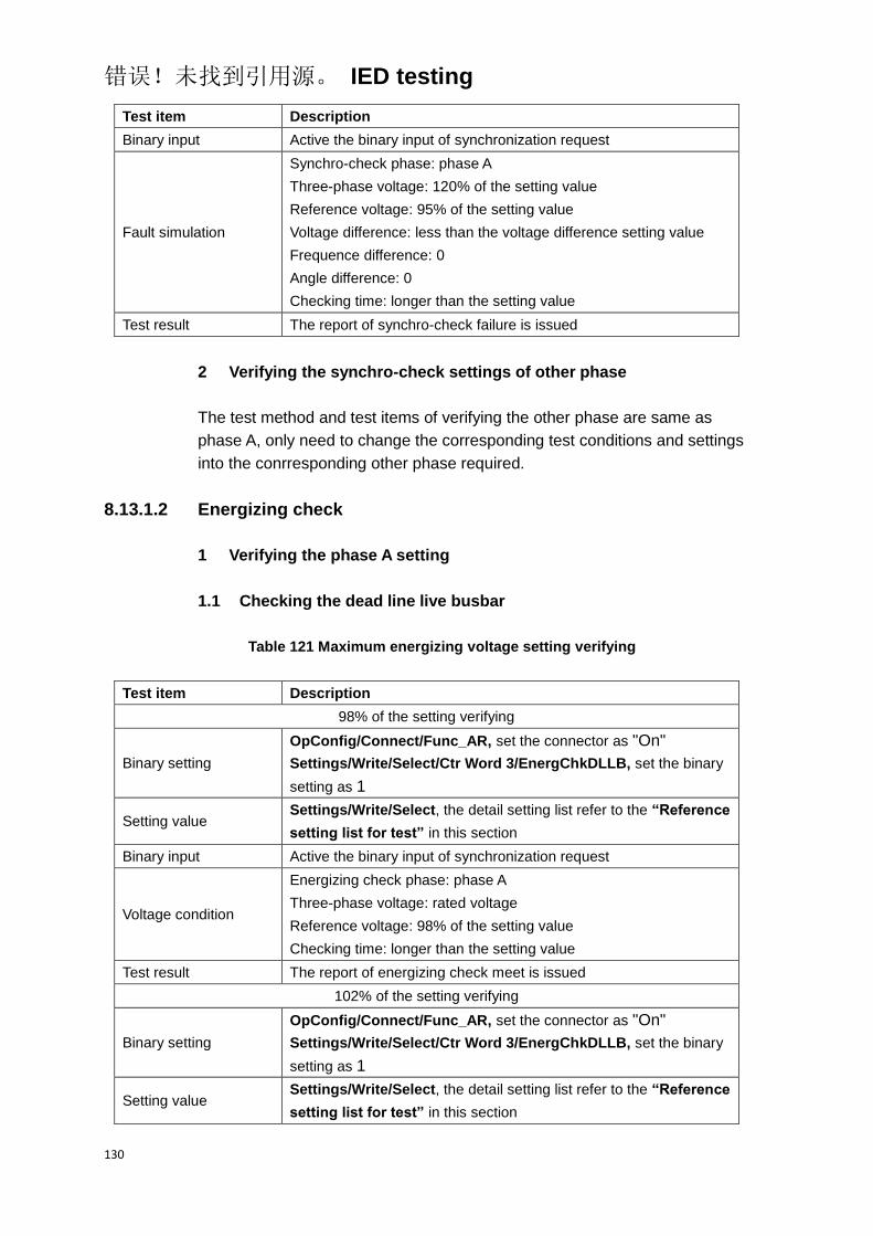
错误!未找到引用源。 IED testing
130
Test item Description
Binary input Active the binary input of synchronization request
Fault simulation
Synchro-check phase: phase A
Three-phase voltage: 120% of the setting value
Reference voltage: 95% of the setting value
Voltage difference: less than the voltage difference setting value
Frequence difference: 0
Angle difference: 0
Checking time: longer than the setting value
Test result The report of synchro-check failure is issued
2 Verifying the synchro-check settings of other phase
The test method and test items of verifying the other phase are same as
phase A, only need to change the corresponding test conditions and settings
into the conrresponding other phase required.
8.13.1.2 Energizing check
1 Verifying the phase A setting
1.1 Checking the dead line live busbar
Table 121 Maximum energizing voltage setting verifying
Test item Description
98% of the setting verifying
Binary setting
OpConfig/Connect/Func_AR, set the connector as "On"
Settings/Write/Select/Ctr Word 3/EnergChkDLLB, set the binary
setting as 1
Setting value Settings/Write/Select, the detail setting list refer to the “Reference
setting list for test” in this section
Binary input Active the binary input of synchronization request
Voltage condition
Energizing check phase: phase A
Three-phase voltage: rated voltage
Reference voltage: 98% of the setting value
Checking time: longer than the setting value
Test result The report of energizing check meet is issued
102% of the setting verifying
Binary setting
OpConfig/Connect/Func_AR, set the connector as "On"
Settings/Write/Select/Ctr Word 3/EnergChkDLLB, set the binary
setting as 1
Setting value Settings/Write/Select, the detail setting list refer to the “Reference
setting list for test” in this section
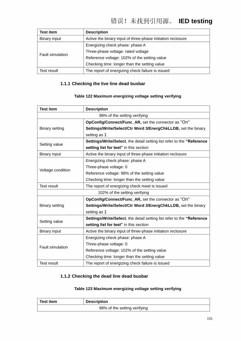
错误!未找到引用源。 IED testing
131
Test item Description
Binary input Active the binary input of three-phase initiation reclosure
Fault simulation
Energizing check phase: phase A
Three-phase voltage: rated voltage
Reference voltage: 102% of the setting value
Checking time: longer than the setting value
Test result The report of energizing check failure is issued
1.1.1 Checking the live line dead busbar
Table 122 Maximum energizing voltage setting verifying
Test item Description
98% of the setting verifying
Binary setting
OpConfig/Connect/Func_AR, set the connector as "On"
Settings/Write/Select/Ctr Word 3/EnergChkLLDB, set the binary
setting as 1
Setting value Settings/Write/Select, the detail setting list refer to the “Reference
setting list for test” in this section
Binary input Active the binary input of three-phase initiation reclosure
Voltage condition
Energizing check phase: phase A
Three-phase voltage: 0
Reference voltage: 98% of the setting value
Checking time: longer than the setting value
Test result The report of energizing check meet is issued
102% of the setting verifying
Binary setting
OpConfig/Connect/Func_AR, set the connector as "On"
Settings/Write/Select/Ctr Word 3/EnergChkLLDB, set the binary
setting as 1
Setting value Settings/Write/Select, the detail setting list refer to the “Reference
setting list for test” in this section
Binary input Active the binary input of three-phase initiation reclosure
Fault simulation
Energizing check phase: phase A
Three-phase voltage: 0
Reference voltage: 102% of the setting value
Checking time: longer than the setting value
Test result The report of energizing check failure is issued
1.1.2 Checking the dead line dead busbar
Table 123 Maximum energizing voltage setting verifying
Test item Description
98% of the setting verifying
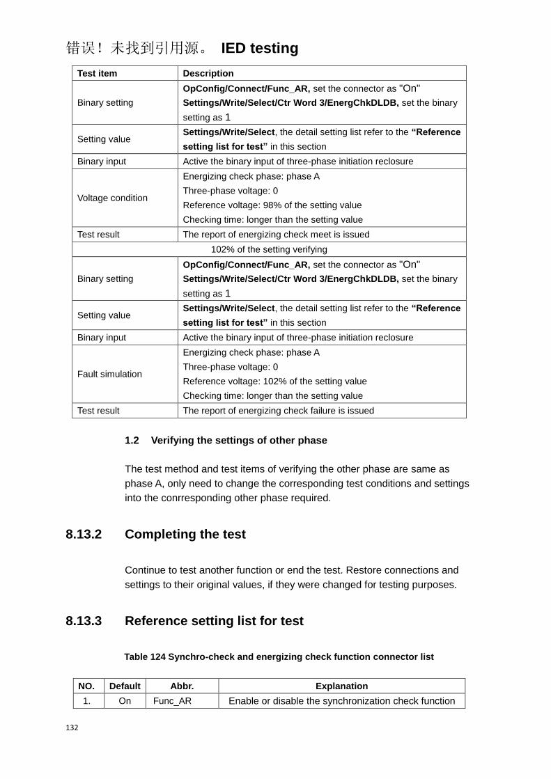
错误!未找到引用源。 IED testing
132
Test item Description
Binary setting
OpConfig/Connect/Func_AR, set the connector as "On"
Settings/Write/Select/Ctr Word 3/EnergChkDLDB, set the binary
setting as 1
Setting value Settings/Write/Select, the detail setting list refer to the “Reference
setting list for test” in this section
Binary input Active the binary input of three-phase initiation reclosure
Voltage condition
Energizing check phase: phase A
Three-phase voltage: 0
Reference voltage: 98% of the setting value
Checking time: longer than the setting value
Test result The report of energizing check meet is issued
102% of the setting verifying
Binary setting
OpConfig/Connect/Func_AR, set the connector as "On"
Settings/Write/Select/Ctr Word 3/EnergChkDLDB, set the binary
setting as 1
Setting value Settings/Write/Select, the detail setting list refer to the “Reference
setting list for test” in this section
Binary input Active the binary input of three-phase initiation reclosure
Fault simulation
Energizing check phase: phase A
Three-phase voltage: 0
Reference voltage: 102% of the setting value
Checking time: longer than the setting value
Test result The report of energizing check failure is issued
1.2 Verifying the settings of other phase
The test method and test items of verifying the other phase are same as
phase A, only need to change the corresponding test conditions and settings
into the conrresponding other phase required.
8.13.2 Completing the test
Continue to test another function or end the test. Restore connections and
settings to their original values, if they were changed for testing purposes.
8.13.3 Reference setting list for test
Table 124 Synchro-check and energizing check function connector list
NO. Default Abbr. Explanation
1. On Func_AR Enable or disable the synchronization check function

错误!未找到引用源。 IED testing
133
NO. Default Abbr. Explanation
2. On Func_MC Enable or disable the synchronization check function
Table 125 Synchro-check and energizing check function setting list
NO. Default Abbr. Explanation Unit Min. Max.
1. 500 T_Syn Chk Time for synchro-check
function S 0.05 60.00
2. 0.1 T_MaxSynExt Maximum time for exiting
synchronization check S 0.05 60.00
3. 0.1 T_MaxSynReq Maximum time for
synchronization check S 0.05 60.00
4. 1 Phase_UL Phase determination setting 1.00 6.00
5. 10 Angle_Syn Diff
Angle difference for
synchro-check function
Degree 1.00 80.00
6. 5 U_Syn Diff
Voltage difference for
synchro-check function
V 1.00 40.00
7. 0.02 Freq_Syn Diff Frequency difference for
synchro-check function HZ 0.02 2.00
8. 43 Umin_Syn Minimum voltage for
synchronization check V 60.00 130.0
9. 17 Umax_Energ Maximum voltage for
Energizing check V 20.00 100.0
Table 126 Synchro-check and energizing check binary setting list
Bit Default “0” “1” Explanation
3.8 1
Selection of AR check mode
Synchrozination check mode
Energizing for DLLB check
mode
Energizing for LLDB check
mode
Energizing for DLDB check
mode
Override mode
3.9 0
3.10 0
3.11 1
Selection of MC check mode
Synchrozination check mode
Energizing for DLLB check
mode
Energizing for LLDB check
mode
Energizing for DLDB check
mode
3.12 0
3.13 0
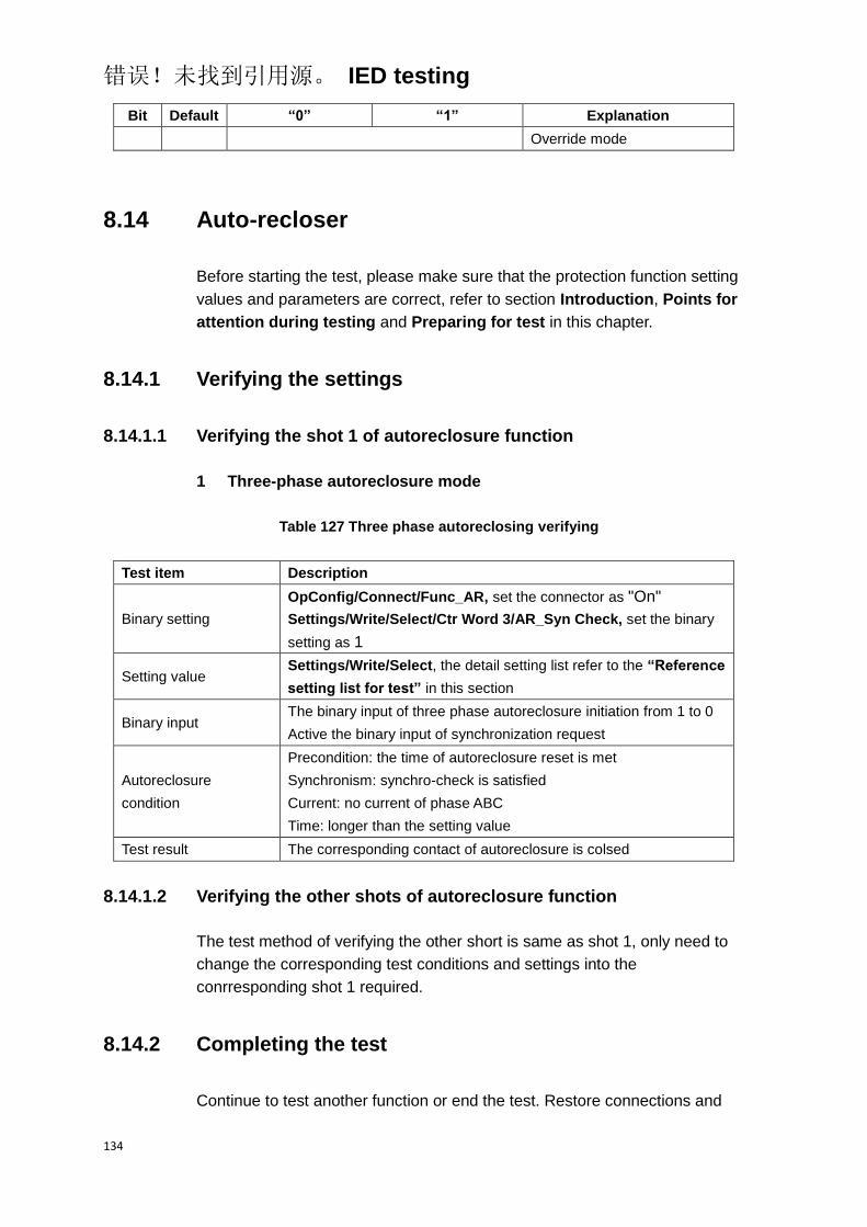
错误!未找到引用源。 IED testing
134
Bit Default “0” “1” Explanation
Override mode
8.14 Auto-recloser
Before starting the test, please make sure that the protection function setting
values and parameters are correct, refer to section Introduction, Points for
attention during testing and Preparing for test in this chapter.
8.14.1 Verifying the settings
8.14.1.1 Verifying the shot 1 of autoreclosure function
1 Three-phase autoreclosure mode
Table 127 Three phase autoreclosing verifying
Test item Description
Binary setting
OpConfig/Connect/Func_AR, set the connector as "On"
Settings/Write/Select/Ctr Word 3/AR_Syn Check, set the binary
setting as 1
Setting value Settings/Write/Select, the detail setting list refer to the “Reference
setting list for test” in this section
Binary input The binary input of three phase autoreclosure initiation from 1 to 0
Active the binary input of synchronization request
Autoreclosure
condition
Precondition: the time of autoreclosure reset is met
Synchronism: synchro-check is satisfied
Current: no current of phase ABC
Time: longer than the setting value
Test result The corresponding contact of autoreclosure is colsed
8.14.1.2 Verifying the other shots of autoreclosure function
The test method of verifying the other short is same as shot 1, only need to
change the corresponding test conditions and settings into the
conrresponding shot 1 required.
8.14.2 Completing the test
Continue to test another function or end the test. Restore connections and
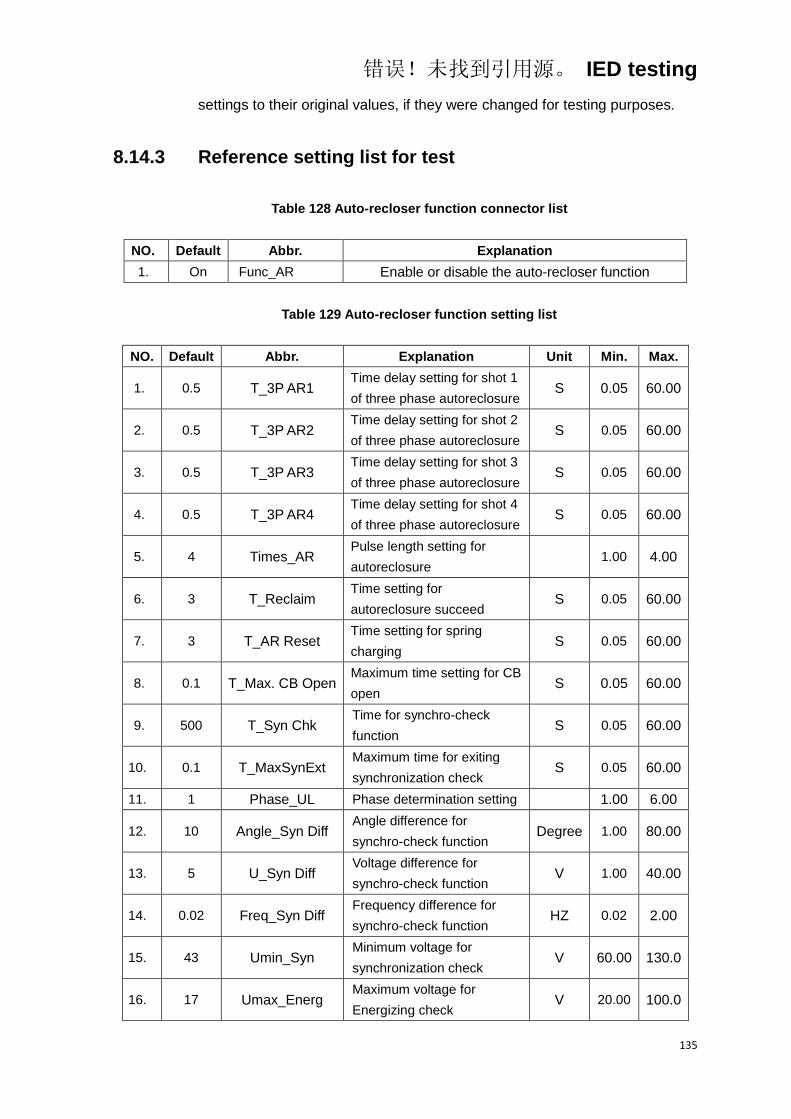
错误!未找到引用源。 IED testing
135
settings to their original values, if they were changed for testing purposes.
8.14.3 Reference setting list for test
Table 128 Auto-recloser function connector list
NO. Default Abbr. Explanation
1. On Func_AR Enable or disable the auto-recloser function
Table 129 Auto-recloser function setting list
NO. Default Abbr. Explanation Unit Min. Max.
1. 0.5 T_3P AR1 Time delay setting for shot 1
of three phase autoreclosure S 0.05 60.00
2. 0.5 T_3P AR2 Time delay setting for shot 2
of three phase autoreclosure S 0.05 60.00
3. 0.5 T_3P AR3 Time delay setting for shot 3
of three phase autoreclosure S 0.05 60.00
4. 0.5 T_3P AR4 Time delay setting for shot 4
of three phase autoreclosure S 0.05 60.00
5. 4 Times_AR Pulse length setting for
autoreclosure 1.00 4.00
6. 3 T_Reclaim Time setting for
autoreclosure succeed S 0.05 60.00
7. 3 T_AR Reset Time setting for spring
charging S 0.05 60.00
8. 0.1 T_Max. CB Open Maximum time setting for CB
open S 0.05 60.00
9. 500 T_Syn Chk Time for synchro-check
function S 0.05 60.00
10. 0.1 T_MaxSynExt Maximum time for exiting
synchronization check S 0.05 60.00
11. 1 Phase_UL Phase determination setting 1.00 6.00
12. 10 Angle_Syn Diff Angle difference for
synchro-check function Degree 1.00 80.00
13. 5 U_Syn Diff Voltage difference for
synchro-check function V 1.00 40.00
14. 0.02 Freq_Syn Diff Frequency difference for
synchro-check function HZ 0.02 2.00
15. 43 Umin_Syn Minimum voltage for
synchronization check V 60.00 130.0
16. 17 Umax_Energ Maximum voltage for
Energizing check V 20.00 100.0

错误!未找到引用源。 IED testing
136
NO. Default Abbr. Explanation Unit Min. Max.
17. 10 T_CB Faulty Time setting for CB faulty S 0.10 60.00
Table 130 Auto-recloser function binary setting list
Bit Default “0” “1” Explanation
3.8 1
Selection of AR check mode
Synchrozination check mode
Energizing for DLLB check
mode
Energizing for LLDB check
mode
Energizing for DLDB check
mode
Override mode
3.9 0
3.10 0
5.0 0 OC1 Init AR Off
Enable or disable the AR
function is initiated by stage 1
of overcurrent protection
5.1 0 OC2 Init AR Off
Enable or disable the AR
function is initiated by stage 2
of overcurrent protection
5.2 0 OC Inv Init AR Off
Enable or disable the AR
function is initiated by inverse
stage of overcurrent
protection
5.3 0 EF1 Init AR Off
Enable or disable the AR
function is initiated by stage 1
of earth fault protection
5.4 0 EF2 Init AR Off
Enable or disable the AR
function is initiated by stage 2
of earth fault protection
5.5 0 EF Inv Init AR Off
Enable or disable the AR
function is initiated by inverse
stage of earth fault protection
5.6 0 SEF1 Init AR Off
Enable or disable the AR
function is initiated by stage 1
of sensitive earth fault
protection
5.7 0 SEF2 Init AR Off
Enable or disable the AR
function is initiated by stage 2
of sensitive earth fault
protection
5.8 0 SEF Inv Init AR Off
Enable or disable the AR
function is initiated by inverse
stage of sensitive earth fault
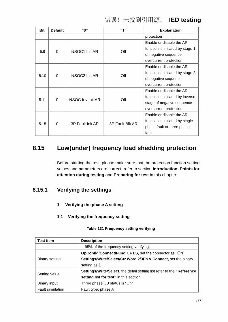
错误!未找到引用源。 IED testing
137
Bit Default “0” “1” Explanation
protection
5.9 0 NSOC1 Init AR Off
Enable or disable the AR
function is initiated by stage 1
of negative sequence
overcurrent protection
5.10 0 NSOC2 Init AR Off
Enable or disable the AR
function is initiated by stage 2
of negative sequence
overcurrent protection
5.11 0 NSOC Inv Init AR Off
Enable or disable the AR
function is initiated by inverse
stage of negative sequence
overcurrent protection
5.15 0 3P Fault Init AR 3P Fault Blk AR
Enable or disable the AR
function is initiated by single
phase fault or three phase
fault
8.15 Low(under) frequency load shedding protection
Before starting the test, please make sure that the protection function setting
values and parameters are correct, refer to section Introduction, Points for
attention during testing and Preparing for test in this chapter.
8.15.1 Verifying the settings
1 Verifying the phase A setting
1.1 Verifying the frequency setting
Table 131 Frequency setting verifying
Test item Description
95% of the frequency setting verifying
Binary setting
OpConfig/Connect/Func_LF LS, set the connector as "On"
Settings/Write/Select/Ctr Word 2/3Ph V Connect, set the binary
setting as 1
Setting value Settings/Write/Select, the detail setting list refer to the “Reference
setting list for test” in this section
Binary input Three phase CB status is “On”
Fault simulation Fault type: phase A

错误!未找到引用源。 IED testing
138
Test item Description
Frequency value: 105% of the low frequency setting
Voltage value: 70% of the voltage checking setting
Current value: 70% of the current checking seeting
Fault time: longer than the setting value
Test result The corresponding output contacts should be closed
105% of the frequency setting verifying
Binary setting
OpConfig/Connect/Func_LF LS, set the connector as "On"
Settings/Write/Select/Ctr Word 2/3Ph V Connect, set the binary
setting as 1
Setting value Settings/Write/Select, the detail setting list refer to the “Reference
setting list for test” in this section
Binary input Three phase CB status is “On”
Fault simulation
Fault type: phase A
Frequency value: 95% of the low frequency setting
Voltage value: 70% of the voltage checking setting
Current value: 70% of the current checking seeting
Fault time: longer than the setting value
Test result The corresponding output contacts should not close
1.2 Verifying the time setting
Table 132 Time setting verifying
Test item Description
Binary setting
OpConfig/Connect/Func_LF LS, set the connector as "On"
Settings/Write/Select/Ctr Word 2/3Ph V Connect, set the binary
setting as 1
Setting value Settings/Write/Select, the detail setting list refer to the “Reference
setting list for test” in this section
Binary input Three phase CB status is “On”
Fault simulation
Fault type: phase A
Frequency value: 70% of the low frequency setting
Voltage value: 70% of the voltage checking setting
Current value: 70% of the current checking seeting
Fault time: longer than the setting value
Test result The corresponding output contacts should be closed, and the
operated time meet the requirement in technical data
1.3 Verifying the voltage setting
Table 133 Voltage setting verifying
Test item Description

错误!未找到引用源。 IED testing
139
Test item Description
95% of the voltage setting verifying
Binary setting
OpConfig/Connect/Func_LF LS, set the connector as "On"
Settings/Write/Select/Ctr Word 2/3Ph V Connect, set the binary
setting as 1
Setting value Settings/Write/Select, the detail setting list refer to the “Reference
setting list for test” in this section
Binary input Three phase CB status is “On”
Fault simulation
Fault type: phase A
Frequency value: 70% of the low frequency setting
Voltage value: 95% of the voltage checking setting
Current value: 70% of the current checking seeting
Fault time: longer than the setting value
Test result The corresponding output contacts should be closed
105% of the voltage setting verifying
Binary setting
OpConfig/Connect/Func_LF LS, set the connector as "On"
Settings/Write/Select/Ctr Word 2/3Ph V Connect, set the binary
setting as 1
Setting value Settings/Write/Select, the detail setting list refer to the “Reference
setting list for test” in this section
Binary input Three phase CB status is “On”
Fault simulation
Fault type: phase A
Frequency value: 70% of the low frequency setting
Voltage value: 105% of the voltage checking setting
Current value: 70% of the current checking seeting
Fault time: longer than the setting value
Test result The corresponding output contacts should not close
1.4 Verifying the current setting
Table 134 Current setting verifying
Test item Description
95% of the current setting verifying
Binary setting
OpConfig/Connect/Func_LF LS, set the connector as "On"
Settings/Write/Select/Ctr Word 2/3Ph V Connect, set the binary
setting as 1
Setting value Settings/Write/Select, the detail setting list refer to the “Reference
setting list for test” in this section
Binary input Three phase CB status is “On”
Fault simulation
Fault type: phase A
Frequency value: 70% of the low frequency setting
Voltage value: 70% of the voltage checking setting
Current value: 95% of the current checking seeting

错误!未找到引用源。 IED testing
140
Test item Description
Fault time: longer than the setting value
Test result The corresponding output contacts should be closed
105% of the voltage setting verifying
Binary setting
OpConfig/Connect/Func_LF LS, set the connector as "On"
Settings/Write/Select/Ctr Word 2/3Ph V Connect, set the binary
setting as 1
Setting value Settings/Write/Select, the detail setting list refer to the “Reference
setting list for test” in this section
Binary input Three phase CB status is “On”
Fault simulation
Fault type: phase A
Frequency value: 70% of the low frequency setting
Voltage value: 105% of the voltage checking setting
Current value: 70% of the current checking seeting
Fault time: longer than the setting value
Test result The corresponding output contacts should not close
1.5 Verifying the dF/dt setting
Table 135 dF/dt setting verifying
Test item Description
105% of the dF/dt setting verifying
Binary setting
OpConfig/Connect/Func_LF LS, set the connector as "On"
Settings/Write/Select/Ctr Word 2/3Ph V Connect, set the binary
setting as 1
Settings/Write/Select/Ctr Word 3/dF(dU)/dt On, set the binary
setting as 1
Setting value Settings/Write/Select, the detail setting list refer to the “Reference
setting list for test” in this section
Binary input Three phase CB status is “On”
Fault simulation
Fault type: phase A
Frequency value: 70% of the low frequency setting
Voltage value: 70% of the voltage checking setting
Current value: 70% of the current checking seeting
dF/dt value: 105% of the setting
Fault time: longer than the setting value
Test result The corresponding output contacts should be closed
95% of the dF/dt setting verifying
Binary setting
OpConfig/Connect/Func_LF LS, set the connector as "On"
Settings/Write/Select/Ctr Word 2/3Ph V Connect, set the binary
setting as 1
Settings/Write/Select/Ctr Word 3/dF(dU)/dt On, set the binary
setting as 1

错误!未找到引用源。 IED testing
141
Test item Description
Setting value Settings/Write/Select, the detail setting list refer to the “Reference
setting list for test” in this section
Binary input Three phase CB status is “On”
Fault simulation
Fault type: phase A
Frequency value: 70% of the low frequency setting
Voltage value: 70% of the voltage checking setting
Current value: 70% of the current checking seeting
dF/dt value: 95% of the setting
Fault time: longer than the setting value
Test result The corresponding output contacts should not close
2 Verifying the settings of other phase
The test method and test items of verifying the other phase are same as
phase A, only need to change the corresponding test conditions and settings
into the conrresponding other phase required.
8.15.2 Completing the test
Continue to test another function or end the test. Restore connections and
settings to their original values, if they were changed for testing purposes.
8.15.3 Reference setting list for test
Table 136 Low frequency load shedding protection connector list
NO. Default Abbr. Explanation
1. On Func_LF LS Enable or disable the low frequency load shedding
protection
Table 137 Low frequency load shedding protection function setting list
NO. Default Abbr. Explanation Unit Min. Max.
1. 49.5 F_LF LS Frequency setting for low frequency
load shedding protection HZ 45.00 60.00
2. 0.5 T_LF LS Time setting for low frequency load
shedding protection S 0.05 60.00
3. 3 dF/dt_LS dF/dt setting for low frequency load
shedding protection HZ/S 1.00 10.00
4. 70 U_Chk Voltage checking setting for low
frequency load shedding protection V 10.00 120.0
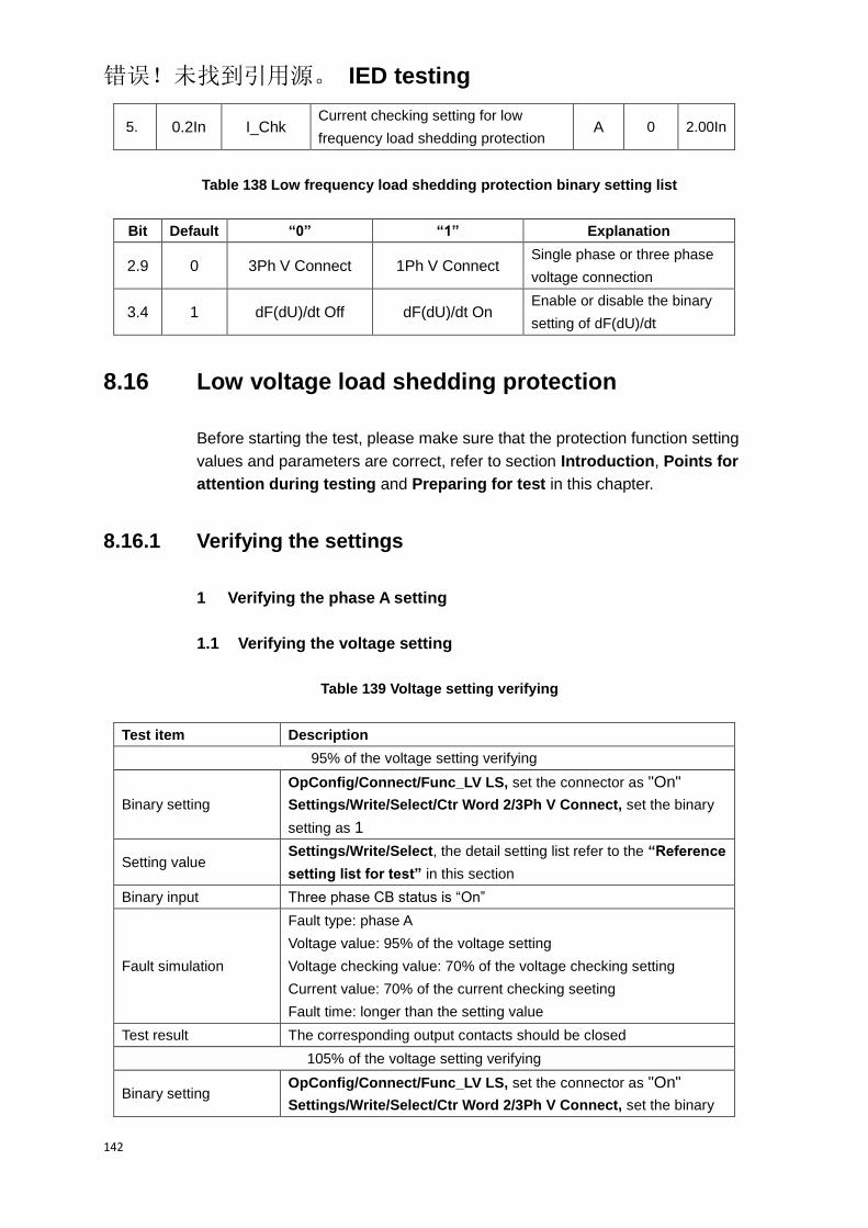
错误!未找到引用源。 IED testing
142
5. 0.2In I_Chk Current checking setting for low
frequency load shedding protection A 0 2.00In
Table 138 Low frequency load shedding protection binary setting list
Bit Default “0” “1” Explanation
2.9 0 3Ph V Connect 1Ph V Connect Single phase or three phase
voltage connection
3.4 1 dF(dU)/dt Off dF(dU)/dt On Enable or disable the binary
setting of dF(dU)/dt
8.16 Low voltage load shedding protection
Before starting the test, please make sure that the protection function setting
values and parameters are correct, refer to section Introduction, Points for
attention during testing and Preparing for test in this chapter.
8.16.1 Verifying the settings
1 Verifying the phase A setting
1.1 Verifying the voltage setting
Table 139 Voltage setting verifying
Test item Description
95% of the voltage setting verifying
Binary setting
OpConfig/Connect/Func_LV LS, set the connector as "On"
Settings/Write/Select/Ctr Word 2/3Ph V Connect, set the binary
setting as 1
Setting value Settings/Write/Select, the detail setting list refer to the “Reference
setting list for test” in this section
Binary input Three phase CB status is “On”
Fault simulation
Fault type: phase A
Voltage value: 95% of the voltage setting
Voltage checking value: 70% of the voltage checking setting
Current value: 70% of the current checking seeting
Fault time: longer than the setting value
Test result The corresponding output contacts should be closed
105% of the voltage setting verifying
Binary setting OpConfig/Connect/Func_LV LS, set the connector as "On"
Settings/Write/Select/Ctr Word 2/3Ph V Connect, set the binary

错误!未找到引用源。 IED testing
143
Test item Description
setting as 1
Setting value Settings/Write/Select, the detail setting list refer to the “Reference
setting list for test” in this section
Binary input Three phase CB status is “On”
Fault simulation
Fault type: phase A
Voltage value: 105% of the voltage setting
Voltage checking value: 70% of the voltage checking setting
Current value: 70% of the current checking seeting
Fault time: longer than the setting value
Test result The corresponding output contacts should not close
1.2 Verifying the time setting
Table 140 Time setting verifying
Test item Description
Binary setting
OpConfig/Connect/Func_LV LS, set the connector as "On"
Settings/Write/Select/Ctr Word 2/3Ph V Connect, set the binary
setting as 1
Setting value Settings/Write/Select, the detail setting list refer to the “Reference
setting list for test” in this section
Binary input Three phase CB status is “On”
Fault simulation
Fault type: phase A
Voltage value: 70% of the voltage setting
Voltage checking value: 70% of the voltage checking setting
Current value: 70% of the current checking seeting
Fault time: longer than the setting value
Test result The corresponding output contacts should be closed, and the
operated time meet the requirement in technical data
1.3 Verifying the voltage checking setting
Table 141 Voltage checking setting verifying
Test item Description
95% of the voltage checking setting verifying
Binary setting
OpConfig/Connect/Func_LV LS, set the connector as "On"
Settings/Write/Select/Ctr Word 2/3Ph V Connect, set the binary
setting as 1
Setting value Settings/Write/Select, the detail setting list refer to the “Reference
setting list for test” in this section
Binary input Three phase CB status is “On”
Fault simulation Fault type: phase A

错误!未找到引用源。 IED testing
144
Test item Description
Voltage value: 70% of the voltage setting
Voltage checking value: 95% of the voltage checking setting
Current value: 70% of the current checking seeting
Fault time: longer than the setting value
Test result The corresponding output contacts should be closed
105% of the voltage checking setting verifying
Binary setting
OpConfig/Connect/Func_LF LS, set the connector as "On"
Settings/Write/Select/Ctr Word 2/3Ph V Connect, set the binary
setting as 1
Setting value Settings/Write/Select, the detail setting list refer to the “Reference
setting list for test” in this section
Binary input Three phase CB status is “On”
Fault simulation
Fault type: phase A
Voltage value: 70% of the voltage setting
Voltage checking value: 105% of the voltage checking setting
Current value: 70% of the current checking seeting
Fault time: longer than the setting value
Test result The corresponding output contacts should not close
1.4 Verifying the current setting
Table 142 Current setting verifying
Test item Description
95% of the current setting verifying
Binary setting
OpConfig/Connect/Func_LF LS, set the connector as "On"
Settings/Write/Select/Ctr Word 2/3Ph V Connect, set the binary
setting as 1
Setting value Settings/Write/Select, the detail setting list refer to the “Reference
setting list for test” in this section
Binary input Three phase CB status is “On”
Fault simulation
Fault type: phase A
Voltage value: 70% of the voltage setting
Voltage checking value: 70% of the voltage checking setting
Current value: 95% of the current checking seeting
Fault time: longer than the setting value
Test result The corresponding output contacts should be closed
105% of the current setting verifying
Binary setting
OpConfig/Connect/Func_LF LS, set the connector as "On"
Settings/Write/Select/Ctr Word 2/3Ph V Connect, set the binary
setting as 1
Setting value Settings/Write/Select, the detail setting list refer to the “Reference
setting list for test” in this section
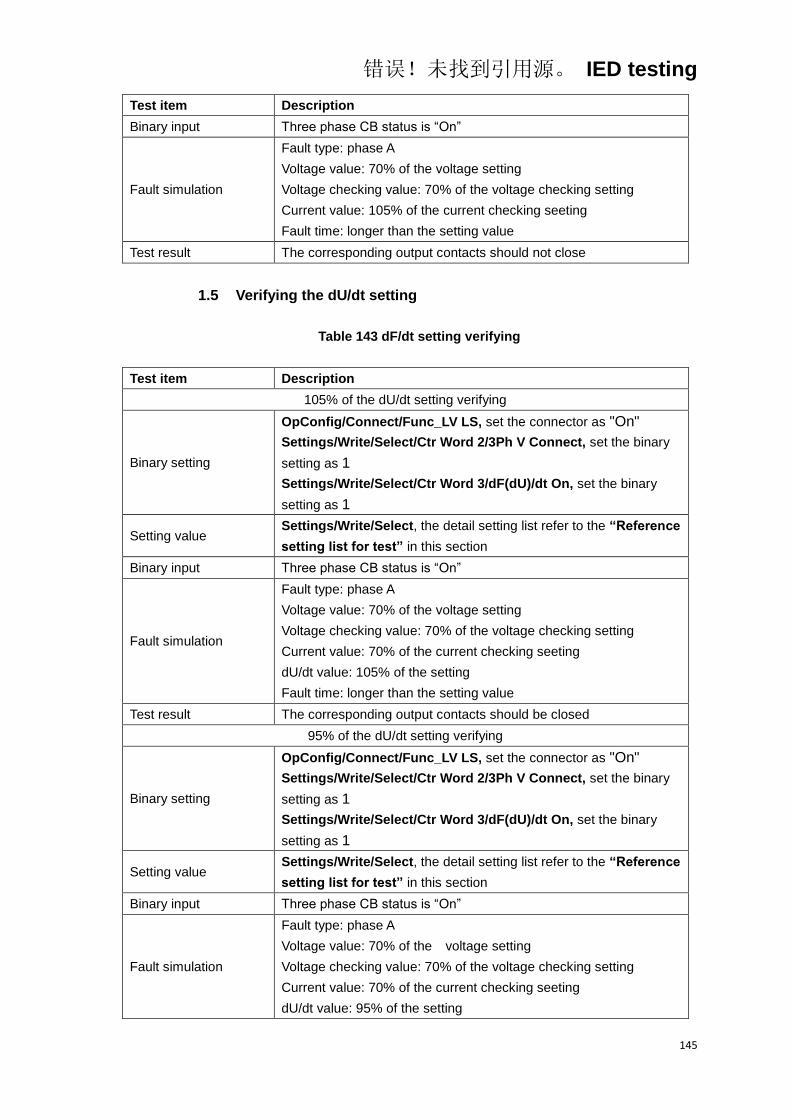
错误!未找到引用源。 IED testing
145
Test item Description
Binary input Three phase CB status is “On”
Fault simulation
Fault type: phase A
Voltage value: 70% of the voltage setting
Voltage checking value: 70% of the voltage checking setting
Current value: 105% of the current checking seeting
Fault time: longer than the setting value
Test result The corresponding output contacts should not close
1.5 Verifying the dU/dt setting
Table 143 dF/dt setting verifying
Test item Description
105% of the dU/dt setting verifying
Binary setting
OpConfig/Connect/Func_LV LS, set the connector as "On"
Settings/Write/Select/Ctr Word 2/3Ph V Connect, set the binary
setting as 1
Settings/Write/Select/Ctr Word 3/dF(dU)/dt On, set the binary
setting as 1
Setting value Settings/Write/Select, the detail setting list refer to the “Reference
setting list for test” in this section
Binary input Three phase CB status is “On”
Fault simulation
Fault type: phase A
Voltage value: 70% of the voltage setting
Voltage checking value: 70% of the voltage checking setting
Current value: 70% of the current checking seeting
dU/dt value: 105% of the setting
Fault time: longer than the setting value
Test result The corresponding output contacts should be closed
95% of the dU/dt setting verifying
Binary setting
OpConfig/Connect/Func_LV LS, set the connector as "On"
Settings/Write/Select/Ctr Word 2/3Ph V Connect, set the binary
setting as 1
Settings/Write/Select/Ctr Word 3/dF(dU)/dt On, set the binary
setting as 1
Setting value Settings/Write/Select, the detail setting list refer to the “Reference
setting list for test” in this section
Binary input Three phase CB status is “On”
Fault simulation
Fault type: phase A
Voltage value: 70% of the voltage setting
Voltage checking value: 70% of the voltage checking setting
Current value: 70% of the current checking seeting
dU/dt value: 95% of the setting
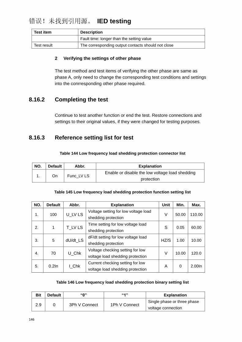
错误!未找到引用源。 IED testing
146
Test item Description
Fault time: longer than the setting value
Test result The corresponding output contacts should not close
2 Verifying the settings of other phase
The test method and test items of verifying the other phase are same as
phase A, only need to change the corresponding test conditions and settings
into the conrresponding other phase required.
8.16.2 Completing the test
Continue to test another function or end the test. Restore connections and
settings to their original values, if they were changed for testing purposes.
8.16.3 Reference setting list for test
Table 144 Low frequency load shedding protection connector list
NO. Default Abbr. Explanation
1. On Func_LV LS Enable or disable the low voltage load shedding
protection
Table 145 Low frequency load shedding protection function setting list
NO. Default Abbr. Explanation Unit Min. Max.
1. 100 U_LV LS Voltage setting for low voltage load
shedding protection V 50.00 110.00
2. 1 T_LV LS Time setting for low voltage load
shedding protection S 0.05 60.00
3. 5 dU/dt_LS dF/dt setting for low voltage load
shedding protection HZ/S 1.00 10.00
4. 70 U_Chk Voltage checking setting for low
voltage load shedding protection V 10.00 120.0
5. 0.2In I_Chk Current checking setting for low
voltage load shedding protection A 0 2.00In
Table 146 Low frequency load shedding protection binary setting list
Bit Default “0” “1” Explanation
2.9 0 3Ph V Connect 1Ph V Connect Single phase or three phase
voltage connection
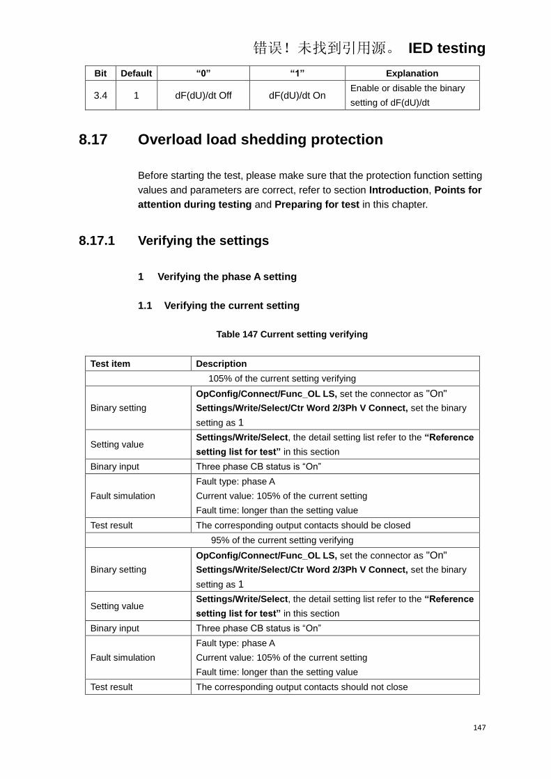
错误!未找到引用源。 IED testing
147
Bit Default “0” “1” Explanation
3.4 1 dF(dU)/dt Off dF(dU)/dt On Enable or disable the binary
setting of dF(dU)/dt
8.17 Overload load shedding protection
Before starting the test, please make sure that the protection function setting
values and parameters are correct, refer to section Introduction, Points for
attention during testing and Preparing for test in this chapter.
8.17.1 Verifying the settings
1 Verifying the phase A setting
1.1 Verifying the current setting
Table 147 Current setting verifying
Test item Description
105% of the current setting verifying
Binary setting
OpConfig/Connect/Func_OL LS, set the connector as "On"
Settings/Write/Select/Ctr Word 2/3Ph V Connect, set the binary
setting as 1
Setting value Settings/Write/Select, the detail setting list refer to the “Reference
setting list for test” in this section
Binary input Three phase CB status is “On”
Fault simulation
Fault type: phase A
Current value: 105% of the current setting
Fault time: longer than the setting value
Test result The corresponding output contacts should be closed
95% of the current setting verifying
Binary setting
OpConfig/Connect/Func_OL LS, set the connector as "On"
Settings/Write/Select/Ctr Word 2/3Ph V Connect, set the binary
setting as 1
Setting value Settings/Write/Select, the detail setting list refer to the “Reference
setting list for test” in this section
Binary input Three phase CB status is “On”
Fault simulation
Fault type: phase A
Current value: 105% of the current setting
Fault time: longer than the setting value
Test result The corresponding output contacts should not close
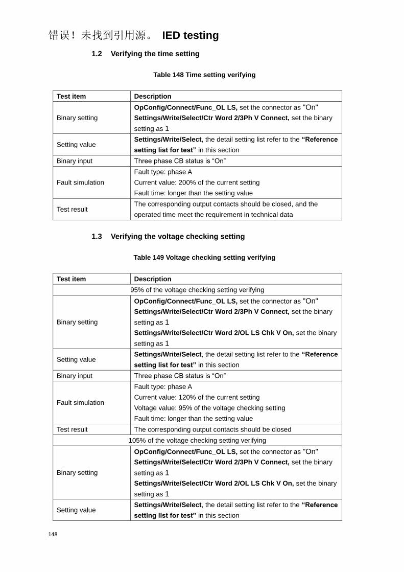
错误!未找到引用源。 IED testing
148
1.2 Verifying the time setting
Table 148 Time setting verifying
Test item Description
Binary setting
OpConfig/Connect/Func_OL LS, set the connector as "On"
Settings/Write/Select/Ctr Word 2/3Ph V Connect, set the binary
setting as 1
Setting value Settings/Write/Select, the detail setting list refer to the “Reference
setting list for test” in this section
Binary input Three phase CB status is “On”
Fault simulation
Fault type: phase A
Current value: 200% of the current setting
Fault time: longer than the setting value
Test result The corresponding output contacts should be closed, and the
operated time meet the requirement in technical data
1.3 Verifying the voltage checking setting
Table 149 Voltage checking setting verifying
Test item Description
95% of the voltage checking setting verifying
Binary setting
OpConfig/Connect/Func_OL LS, set the connector as "On"
Settings/Write/Select/Ctr Word 2/3Ph V Connect, set the binary
setting as 1
Settings/Write/Select/Ctr Word 2/OL LS Chk V On, set the binary
setting as 1
Setting value Settings/Write/Select, the detail setting list refer to the “Reference
setting list for test” in this section
Binary input Three phase CB status is “On”
Fault simulation
Fault type: phase A
Current value: 120% of the current setting
Voltage value: 95% of the voltage checking setting
Fault time: longer than the setting value
Test result The corresponding output contacts should be closed
105% of the voltage checking setting verifying
Binary setting
OpConfig/Connect/Func_OL LS, set the connector as "On"
Settings/Write/Select/Ctr Word 2/3Ph V Connect, set the binary
setting as 1
Settings/Write/Select/Ctr Word 2/OL LS Chk V On, set the binary
setting as 1
Setting value Settings/Write/Select, the detail setting list refer to the “Reference
setting list for test” in this section

错误!未找到引用源。 IED testing
149
Test item Description
Binary input Three phase CB status is “On”
Fault simulation
Fault type: phase A
Current value: 120% of the current setting
Voltage value: 105% of the voltage checking setting
Fault time: longer than the setting value
Test result The corresponding output contacts should not close
1.4 Verifying the dF/dt setting
Table 150 dF/dt setting verifying
Test item Description
105% of the dF/dt setting verifying
Binary setting
OpConfig/Connect/Func_OL LS, set the connector as "On"
Settings/Write/Select/Ctr Word 2/3Ph V Connect, set the binary
setting as 1
Settings/Write/Select/Ctr Word 3/dF(dU)/dt On, set the binary
setting as 1
Setting value Settings/Write/Select, the detail setting list refer to the “Reference
setting list for test” in this section
Binary input Three phase CB status is “On”
Fault simulation
Fault type: phase A
Current value: 120% of the current setting
dF/dt value: 105% of the setting
dU/dt value: 120% of the setting
Fault time: longer than the setting value
Test result The corresponding output contacts should be closed
95% of the dF/dt setting verifying
Binary setting
OpConfig/Connect/Func_OL LS, set the connector as "On"
Settings/Write/Select/Ctr Word 2/3Ph V Connect, set the binary
setting as 1
Settings/Write/Select/Ctr Word 3/dF(dU)/dt On, set the binary
setting as 1
Setting value Settings/Write/Select, the detail setting list refer to the “Reference
setting list for test” in this section
Binary input Three phase CB status is “On”
Fault simulation
Fault type: phase A
Current value: 120% of the current setting
dF/dt value: 95% of the setting
dU/dt value: 120% of the setting
Fault time: longer than the setting value
Test result The corresponding output contacts should not close

错误!未找到引用源。 IED testing
150
1.5 Verifying the dU/dt setting
Table 151 dU/dt setting verifying
Test item Description
105% of the dU/dt setting verifying
Binary setting
OpConfig/Connect/Func_OL LS, set the connector as "On"
Settings/Write/Select/Ctr Word 2/3Ph V Connect, set the binary
setting as 1
Settings/Write/Select/Ctr Word 3/dF(dU)/dt On, set the binary
setting as 1
Setting value Settings/Write/Select, the detail setting list refer to the “Reference
setting list for test” in this section
Binary input Three phase CB status is “On”
Fault simulation
Fault type: phase A
Current value: 120% of the current setting
dF/dt value: 120% of the setting
dU/dt value: 105% of the setting
Fault time: longer than the setting value
Test result The corresponding output contacts should be closed
95% of the dU/dt setting verifying
Binary setting
OpConfig/Connect/Func_LV LS, set the connector as "On"
Settings/Write/Select/Ctr Word 2/3Ph V Connect, set the binary
setting as 1
Settings/Write/Select/Ctr Word 3/dF(dU)/dt On, set the binary
setting as 1
Setting value Settings/Write/Select, the detail setting list refer to the “Reference
setting list for test” in this section
Binary input Three phase CB status is “On”
Fault simulation
Fault type: phase A
Current value: 120% of the current setting
dF/dt value: 105% of the setting
dU/dt value: 95% of the setting
Fault time: longer than the setting value
Test result The corresponding output contacts should not close
2 Verifying the settings of other phase
The test method and test items of verifying the other phase are same as
phase A, only need to change the corresponding test conditions and settings
into the conrresponding other phase required.
8.17.2 Completing the test
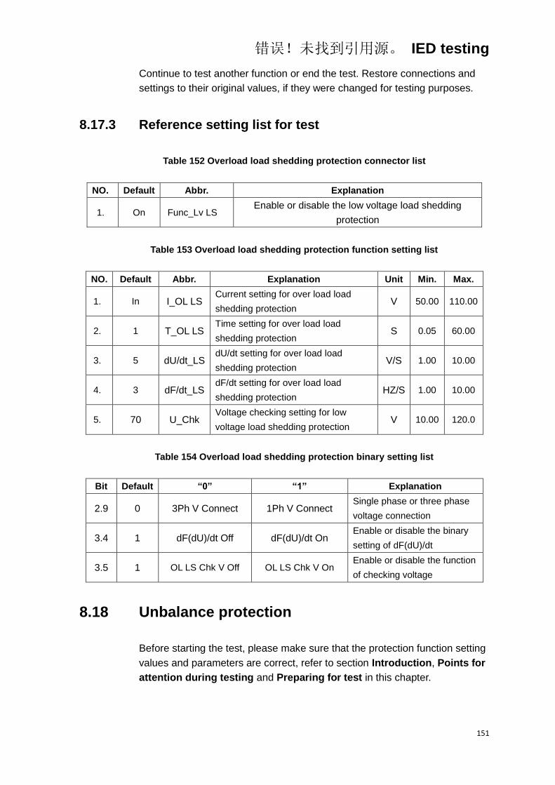
错误!未找到引用源。 IED testing
151
Continue to test another function or end the test. Restore connections and
settings to their original values, if they were changed for testing purposes.
8.17.3 Reference setting list for test
Table 152 Overload load shedding protection connector list
NO. Default Abbr. Explanation
1. On Func_Lv LS Enable or disable the low voltage load shedding
protection
Table 153 Overload load shedding protection function setting list
NO. Default Abbr. Explanation Unit Min. Max.
1. In I_OL LS Current setting for over load load
shedding protection V 50.00 110.00
2. 1 T_OL LS Time setting for over load load
shedding protection S 0.05 60.00
3. 5 dU/dt_LS dU/dt setting for over load load
shedding protection V/S 1.00 10.00
4. 3 dF/dt_LS dF/dt setting for over load load
shedding protection HZ/S 1.00 10.00
5. 70 U_Chk Voltage checking setting for low
voltage load shedding protection V 10.00 120.0
Table 154 Overload load shedding protection binary setting list
Bit Default “0” “1” Explanation
2.9 0 3Ph V Connect 1Ph V Connect Single phase or three phase
voltage connection
3.4 1 dF(dU)/dt Off dF(dU)/dt On Enable or disable the binary
setting of dF(dU)/dt
3.5 1 OL LS Chk V Off OL LS Chk V On Enable or disable the function
of checking voltage
8.18 Unbalance protection
Before starting the test, please make sure that the protection function setting
values and parameters are correct, refer to section Introduction, Points for
attention during testing and Preparing for test in this chapter.

错误!未找到引用源。 IED testing
152
8.18.1 Verifying the settings
8.18.1.1 Verifying the setting for tripping
1 Verifying the phase A setting
1.1 Verifying the current setting
Table 155 Current setting verifying
Test item Description
105% of the current setting verifying
Binary setting OpConfig/Connect/Func_UBL, set the connector as "On"
Setting value Settings/Write/Select, the detail setting list refer to the “Reference
setting list for test” in this section
Binary input Three phase CB status is “On”
Fault simulation
Fault type: phase A
Current value: 105% of the current setting
Fault time: longer than the setting value
Test result The corresponding output contacts should be closed
95% of the current setting verifying
Binary setting OpConfig/Connect/Func_UBL, set the connector as "On"
Setting value Settings/Write/Select, the detail setting list refer to the “Reference
setting list for test” in this section
Binary input Three phase CB status is “On”
Fault simulation
Fault type: phase A
Current value: 105% of the current setting
Fault time: longer than the setting value
Test result The corresponding output contacts should not close
1.2 Verifying the voltage setting
Table 156 Voltage setting verifying
Test item Description
105% of the voltage setting verifying
Binary setting OpConfig/Connect/Func_UBL, set the connector as "On"
Setting value Settings/Write/Select, the detail setting list refer to the “Reference
setting list for test” in this section
Binary input Three phase CB status is “On”
Fault simulation
Fault type: phase A
Voltage value: 105% of the voltage setting
Fault time: longer than the setting value

错误!未找到引用源。 IED testing
153
Test item Description
Test result The corresponding output contacts should be closed
95% of the voltage setting verifying
Binary setting OpConfig/Connect/Func_UBL, set the connector as "On"
Setting value Settings/Write/Select, the detail setting list refer to the “Reference
setting list for test” in this section
Binary input Three phase CB status is “On”
Fault simulation
Fault type: phase A
Voltage value: 105% of the voltage setting
Fault time: longer than the setting value
Test result The corresponding output contacts should not close
1.3 Verifying the time setting
Table 157 Time setting verifying
Test item Description
Binary setting OpConfig/Connect/Func_UBL, set the connector as "On"
Setting value Settings/Write/Select, the detail setting list refer to the “Reference
setting list for test” in this section
Binary input Three phase CB status is “On”
Fault simulation
Fault type: phase A
Current value: 200% of the current setting
Fault time: longer than the setting value
Test result The corresponding output contacts should be closed, and the
operated time meet the requirement in technical data
2 Verifying the settings of other phase
The test method and test items of verifying the other phase are same as
phase A, only need to change the corresponding test conditions and settings
into the conrresponding other phase required.
8.18.1.2 Verifying the setting for alarming
1 Verifying the phase A setting
1.1 Verifying the current setting
Table 158 Current setting verifying
Test item Description
105% of the current setting verifying
Binary setting OpConfig/Connect/Func_UBL, set the connector as "On"
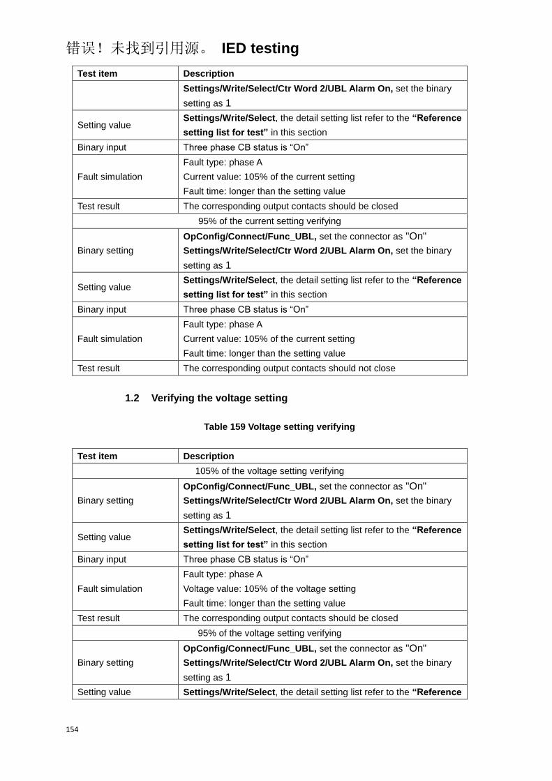
错误!未找到引用源。 IED testing
154
Test item Description
Settings/Write/Select/Ctr Word 2/UBL Alarm On, set the binary
setting as 1
Setting value Settings/Write/Select, the detail setting list refer to the “Reference
setting list for test” in this section
Binary input Three phase CB status is “On”
Fault simulation
Fault type: phase A
Current value: 105% of the current setting
Fault time: longer than the setting value
Test result The corresponding output contacts should be closed
95% of the current setting verifying
Binary setting
OpConfig/Connect/Func_UBL, set the connector as "On"
Settings/Write/Select/Ctr Word 2/UBL Alarm On, set the binary
setting as 1
Setting value Settings/Write/Select, the detail setting list refer to the “Reference
setting list for test” in this section
Binary input Three phase CB status is “On”
Fault simulation
Fault type: phase A
Current value: 105% of the current setting
Fault time: longer than the setting value
Test result The corresponding output contacts should not close
1.2 Verifying the voltage setting
Table 159 Voltage setting verifying
Test item Description
105% of the voltage setting verifying
Binary setting
OpConfig/Connect/Func_UBL, set the connector as "On"
Settings/Write/Select/Ctr Word 2/UBL Alarm On, set the binary
setting as 1
Setting value Settings/Write/Select, the detail setting list refer to the “Reference
setting list for test” in this section
Binary input Three phase CB status is “On”
Fault simulation
Fault type: phase A
Voltage value: 105% of the voltage setting
Fault time: longer than the setting value
Test result The corresponding output contacts should be closed
95% of the voltage setting verifying
Binary setting
OpConfig/Connect/Func_UBL, set the connector as "On"
Settings/Write/Select/Ctr Word 2/UBL Alarm On, set the binary
setting as 1
Setting value Settings/Write/Select, the detail setting list refer to the “Reference

错误!未找到引用源。 IED testing
155
Test item Description
setting list for test” in this section
Binary input Three phase CB status is “On”
Fault simulation
Fault type: phase A
Voltage value: 105% of the voltage setting
Fault time: longer than the setting value
Test result The corresponding output contacts should not close
1.3 Verifying the time setting
Table 160 Time setting verifying
Test item Description
Binary setting
OpConfig/Connect/Func_UBL, set the connector as "On"
Settings/Write/Select/Ctr Word 2/UBL Alarm On, set the binary
setting as 1
Setting value Settings/Write/Select, the detail setting list refer to the “Reference
setting list for test” in this section
Binary input Three phase CB status is “On”
Fault simulation
Fault type: phase A
Current value: 200% of the current setting
Fault time: longer than the setting value
Test result The corresponding output contacts should be closed, and the
operated time meet the requirement in technical data
2 Verifying the settings of other phase
The test method and test items of verifying the other phase are same as
phase A, only need to change the corresponding test conditions and settings
into the conrresponding other phase required.
8.18.2 Completing the test
Continue to test another function or end the test. Restore connections and
settings to their original values, if they were changed for testing purposes.
8.18.3 Reference setting list for test
Table 161 Unbalance protection connector list
NO. Default Abbr. Explanation
1. On Func_UBL Enable or disable the unbalance protection

错误!未找到引用源。 IED testing
156
Table 162 Unbalance protection function setting list
NO. Default Abbr. Explanation Unit Min. Max.
1. U_UBL Alarm Voltage setting for alarm of
unbalance protection V 0.50 100.0
2. I_UBL Alarm Current setting for alarm of
unbalance protection A 0.10 20.0
3. T_UBL Alarm Time setting for alarm of
unbalance protection S 0.10 60.00
4. U_UBL Trip Voltage setting for tripping of
unbalance protection V 0.50 100.0
5. I_UBL Trip Current setting for tripping of
unbalance protection A 0.10 20.0
6. T_UBL Trip Time setting for tripping of
unbalance protection S 0.00 60.00
Table 163 Unbalance protection binary setting list
Bit Default “0” “1” Explanation
4.8 UBL Alarm Off UBL Alarm On
Enable or disable the alarm
function of unbalance
protection
8.19 Under current monitoring
Before starting the test, please make sure that the protection function setting
values and parameters are correct, refer to section Introduction, Points for
attention during testing and Preparing for test in this chapter.
8.19.1 Verifying the settings
1 Verifying the phase A setting
1.1 Verifying the current setting
Table 164 Current setting verifying
Test item Description
95% of the current setting verifying
Binary setting OpConfig/Connect/Func_UC, set the connector as "On"
Setting value Settings/Write/Select, the detail setting list refer to the “Reference
setting list for test” in this section
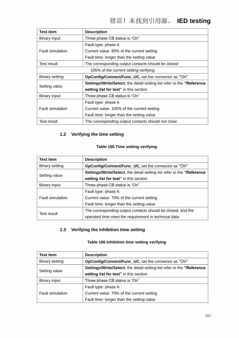
错误!未找到引用源。 IED testing
157
Test item Description
Binary input Three phase CB status is “On”
Fault simulation
Fault type: phase A
Current value: 95% of the current setting
Fault time: longer than the setting value
Test result The corresponding output contacts should be closed
105% of the current setting verifying
Binary setting OpConfig/Connect/Func_UC, set the connector as "On"
Setting value Settings/Write/Select, the detail setting list refer to the “Reference
setting list for test” in this section
Binary input Three phase CB status is “On”
Fault simulation
Fault type: phase A
Current value: 105% of the current setting
Fault time: longer than the setting value
Test result The corresponding output contacts should not close
1.2 Verifying the time setting
Table 165 Time setting verifying
Test item Description
Binary setting OpConfig/Connect/Func_UC, set the connector as "On"
Setting value Settings/Write/Select, the detail setting list refer to the “Reference
setting list for test” in this section
Binary input Three phase CB status is “On”
Fault simulation
Fault type: phase A
Current value: 70% of the current setting
Fault time: longer than the setting value
Test result The corresponding output contacts should be closed, and the
operated time meet the requirement in technical data
1.3 Verifying the inhibition time setting
Table 166 Inhibition time setting verifying
Test item Description
Binary setting OpConfig/Connect/Func_UC, set the connector as "On"
Setting value Settings/Write/Select, the detail setting list refer to the “Reference
setting list for test” in this section
Binary input Three phase CB status is “On”
Fault simulation
Fault type: phase A
Current value: 70% of the current setting
Fault time: longer than the setting value

错误!未找到引用源。 IED testing
158
Test item Description
Test result The corresponding output contacts should be closed, and the
inhibition time meet the requirement in technical data
2 Verifying the settings of other phase
The test method and test items of verifying the other phase are same as
phase A, only need to change the corresponding test conditions and settings
into the conrresponding other phase required.
8.19.2 Completing the test
Continue to test another function or end the test. Restore connections and
settings to their original values, if they were changed for testing purposes.
8.19.3 Reference setting list for test
Table 167 Under current protection connector list
NO. Default Abbr. Explanation
1. On Func_UC Enable or disable the under current protection
Table 168 Unbalance protection function setting list
NO. Default Abbr. Explanation Unit Min. Max.
1. I_UC Current setting for under current
protection A 0.50In 20.00In
2. T_UC Time setting for tripping of under
current protection S 0.10 60.00
3. T_Inhibition Time setting for inhibition of under
current protection S 30.00 6000.0
8.20 Current overload monitoring
Before starting the test, please make sure that the protection function setting
values and parameters are correct, refer to section Introduction, Points for
attention during testing and Preparing for test in this chapter.
8.20.1 Verifying the settings
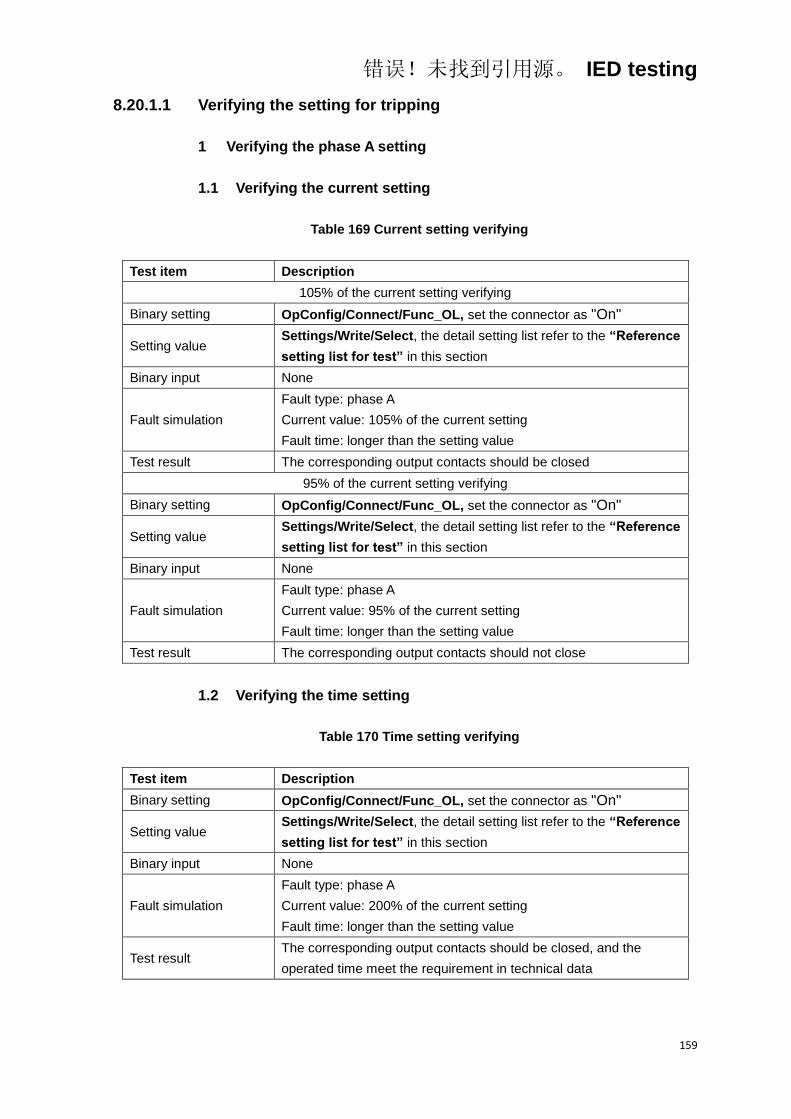
错误!未找到引用源。 IED testing
159
8.20.1.1 Verifying the setting for tripping
1 Verifying the phase A setting
1.1 Verifying the current setting
Table 169 Current setting verifying
Test item Description
105% of the current setting verifying
Binary setting OpConfig/Connect/Func_OL, set the connector as "On"
Setting value Settings/Write/Select, the detail setting list refer to the “Reference
setting list for test” in this section
Binary input None
Fault simulation
Fault type: phase A
Current value: 105% of the current setting
Fault time: longer than the setting value
Test result The corresponding output contacts should be closed
95% of the current setting verifying
Binary setting OpConfig/Connect/Func_OL, set the connector as "On"
Setting value Settings/Write/Select, the detail setting list refer to the “Reference
setting list for test” in this section
Binary input None
Fault simulation
Fault type: phase A
Current value: 95% of the current setting
Fault time: longer than the setting value
Test result The corresponding output contacts should not close
1.2 Verifying the time setting
Table 170 Time setting verifying
Test item Description
Binary setting OpConfig/Connect/Func_OL, set the connector as "On"
Setting value Settings/Write/Select, the detail setting list refer to the “Reference
setting list for test” in this section
Binary input None
Fault simulation
Fault type: phase A
Current value: 200% of the current setting
Fault time: longer than the setting value
Test result The corresponding output contacts should be closed, and the
operated time meet the requirement in technical data
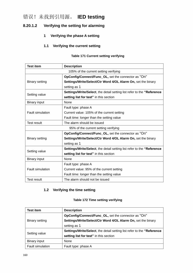
错误!未找到引用源。 IED testing
160
8.20.1.2 Verifying the setting for alarming
1 Verifying the phase A setting
1.1 Verifying the current setting
Table 171 Current setting verifying
Test item Description
105% of the current setting verifying
Binary setting
OpConfig/Connect/Func_OL, set the connector as "On"
Settings/Write/Select/Ctr Word 4/OL Alarm On, set the binary
setting as 1
Setting value Settings/Write/Select, the detail setting list refer to the “Reference
setting list for test” in this section
Binary input None
Fault simulation
Fault type: phase A
Current value: 105% of the current setting
Fault time: longer than the setting value
Test result The alarm should be issued
95% of the current setting verifying
Binary setting
OpConfig/Connect/Func_OL, set the connector as "On"
Settings/Write/Select/Ctr Word 4/OL Alarm On, set the binary
setting as 1
Setting value Settings/Write/Select, the detail setting list refer to the “Reference
setting list for test” in this section
Binary input None
Fault simulation
Fault type: phase A
Current value: 95% of the current setting
Fault time: longer than the setting value
Test result The alarm should not be issued
1.2 Verifying the time setting
Table 172 Time setting verifying
Test item Description
Binary setting
OpConfig/Connect/Func_OL, set the connector as "On"
Settings/Write/Select/Ctr Word 4/OL Alarm On, set the binary
setting as 1
Setting value Settings/Write/Select, the detail setting list refer to the “Reference
setting list for test” in this section
Binary input None
Fault simulation Fault type: phase A

错误!未找到引用源。 IED testing
161
Test item Description
Current value: 200% of the current setting
Fault time: longer than the setting value
Test result The alarm should be issued, and the alarm time meet the
requirement in technical data
2 Verifying the settings of other phase
The test method and test items of verifying the other phase are same as
phase A, only need to change the corresponding test conditions and settings
into the conrresponding other phase required.
8.20.2 Completing the test
Continue to test another function or end the test. Restore connections and
settings to their original values, if they were changed for testing purposes.
8.20.3 Reference setting list for test
Table 173 Current overload protection connector list
NO. Default Abbr. Explanation
1. On Func_OL Enable or disable the current overload protection
Table 174 Current overload protection function setting list
NO. Default Abbr. Explanation Unit Min. Max.
1. I_OL Alarm Current setting for alarm of current
overload protection A 0.50In 20.00In
2. T_OL Alarm Time setting for alarm of current
overload protection S 0.10 6000.0
3. I_OL Trip Current setting for tripping of
current overload protection A 0.50In 20.00In
4. T_OL Trip Time setting for tripping of current
overload protection S 0.10 6000.0
Table 175 Current overload protection binary setting list
Bit Default “0” “1” Explanation
4.7 OL Alarm Off OL Alarm On
Enable or disable the alarm
function of current overload
protection

错误!未找到引用源。 IED testing
162
8.21 Control circuit faulty supervising
Before starting the test, please make sure that the protection function setting
values and parameters are correct, refer to section Introduction, Points for
attention during testing and Preparing for test in this chapter.
8.21.1 Verifying the settings
8.21.1.1 Verifying the CB status
Table 176 CB status verifying
Test item Description
Active One of the two binary input
Binary setting Settings/Write/Select/Ctr Word 4/CB Faulty On, set the binary
setting as 1
Setting value Settings/Write/Select, the detail setting list refer to the “Reference
setting list for test” in this section
Binary input Active the binary input “3Ph CB Open” or “3Ph CB Close”
Fault simulation Active time: longer than the setting value
Test result The alarm should not be issued
Active both of the two binary input
Binary setting Settings/Write/Select/Ctr Word 4/CB Faulty On, set the binary
setting as 1
Setting value Settings/Write/Select, the detail setting list refer to the “Reference
setting list for test” in this section
Binary input Active the binary input “3Ph CB Open” and “3Ph CB Close”
Fault simulation Active time: longer than the setting value
Test result The alarm should be issued
8.21.1.2 Verifying the DS(Disconnection switch) status
Table 177 DS status verifying
Test item Description
Active One of the two binary input
Binary setting Settings/Write/Select/Ctr Word 4/DS Faulty On, set the binary
setting as 1
Setting value Settings/Write/Select, the detail setting list refer to the “Reference
setting list for test” in this section
Binary input Active the binary input “DS Open” or “DS Close”
Fault simulation Active time: longer than the setting value

错误!未找到引用源。 IED testing
163
Test item Description
Test result The alarm should not be issued
Active both of the two binary input
Binary setting Settings/Write/Select/Ctr Word 4/DS Faulty On, set the binary
setting as 1
Setting value Settings/Write/Select, the detail setting list refer to the “Reference
setting list for test” in this section
Binary input Active the binary input “DS Open” and “DS Close”
Fault simulation Active time: longer than the setting value
Test result The alarm should be issued
8.21.1.3 Verifying the ES(Earth switch) status
Table 178 ES status verifying
Test item Description
Active One of the two binary input
Binary setting Settings/Write/Select/Ctr Word 4/ES Faulty On, set the binary
setting as 1
Setting value Settings/Write/Select, the detail setting list refer to the “Reference
setting list for test” in this section
Binary input Active the binary input “ES Open” or “ES Close”
Fault simulation Active time: longer than the setting value
Test result The alarm should not be issued
Active both of the two binary input
Binary setting Settings/Write/Select/Ctr Word 4/ES Faulty On, set the binary
setting as 1
Setting value Settings/Write/Select, the detail setting list refer to the “Reference
setting list for test” in this section
Binary input Active the binary input “ES Open” and “ES Close”
Fault simulation Active time: longer than the setting value
Test result The alarm should be issued
8.21.2 Completing the test
Continue to test another function or end the test. Restore connections and
settings to their original values, if they were changed for testing purposes.
8.21.3 Reference setting list for test
Table 179 Control circuit faulty supervising function setting list
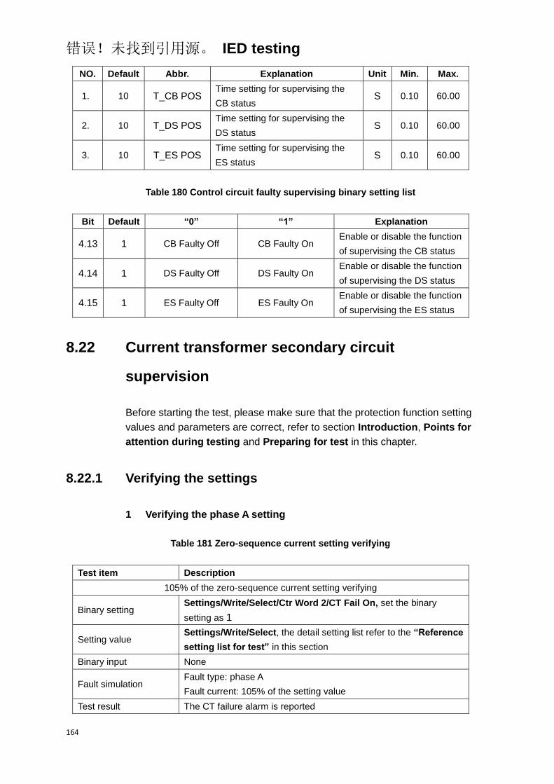
错误!未找到引用源。 IED testing
164
NO. Default Abbr. Explanation Unit Min. Max.
1. 10 T_CB POS Time setting for supervising the
CB status S 0.10 60.00
2. 10 T_DS POS Time setting for supervising the
DS status S 0.10 60.00
3. 10 T_ES POS Time setting for supervising the
ES status S 0.10 60.00
Table 180 Control circuit faulty supervising binary setting list
Bit Default “0” “1” Explanation
4.13 1 CB Faulty Off CB Faulty On Enable or disable the function
of supervising the CB status
4.14 1 DS Faulty Off DS Faulty On Enable or disable the function
of supervising the DS status
4.15 1 ES Faulty Off ES Faulty On Enable or disable the function
of supervising the ES status
8.22 Current transformer secondary circuit
supervision
Before starting the test, please make sure that the protection function setting
values and parameters are correct, refer to section Introduction, Points for
attention during testing and Preparing for test in this chapter.
8.22.1 Verifying the settings
1 Verifying the phase A setting
Table 181 Zero-sequence current setting verifying
Test item Description
105% of the zero-sequence current setting verifying
Binary setting Settings/Write/Select/Ctr Word 2/CT Fail On, set the binary
setting as 1
Setting value Settings/Write/Select, the detail setting list refer to the “Reference
setting list for test” in this section
Binary input None
Fault simulation Fault type: phase A
Fault current: 105% of the setting value
Test result The CT failure alarm is reported
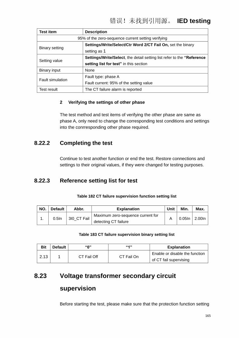
错误!未找到引用源。 IED testing
165
Test item Description
95% of the zero-sequence current setting verifying
Binary setting Settings/Write/Select/Ctr Word 2/CT Fail On, set the binary
setting as 1
Setting value Settings/Write/Select, the detail setting list refer to the “Reference
setting list for test” in this section
Binary input None
Fault simulation Fault type: phase A
Fault current: 95% of the setting value
Test result The CT failure alarm is reported
2 Verifying the settings of other phase
The test method and test items of verifying the other phase are same as
phase A, only need to change the corresponding test conditions and settings
into the conrresponding other phase required.
8.22.2 Completing the test
Continue to test another function or end the test. Restore connections and
settings to their original values, if they were changed for testing purposes.
8.22.3 Reference setting list for test
Table 182 CT failure supervision function setting list
NO. Default Abbr. Explanation Unit Min. Max.
1. 0.5In 3I0_CT Fail Maximum zero-sequence current for
detecting CT failure A 0.05In 2.00In
Table 183 CT failure supervision binary setting list
Bit Default “0” “1” Explanation
2.13 1 CT Fail Off CT Fail On Enable or disable the function
of CT fail supervising
8.23 Voltage transformer secondary circuit
supervision
Before starting the test, please make sure that the protection function setting
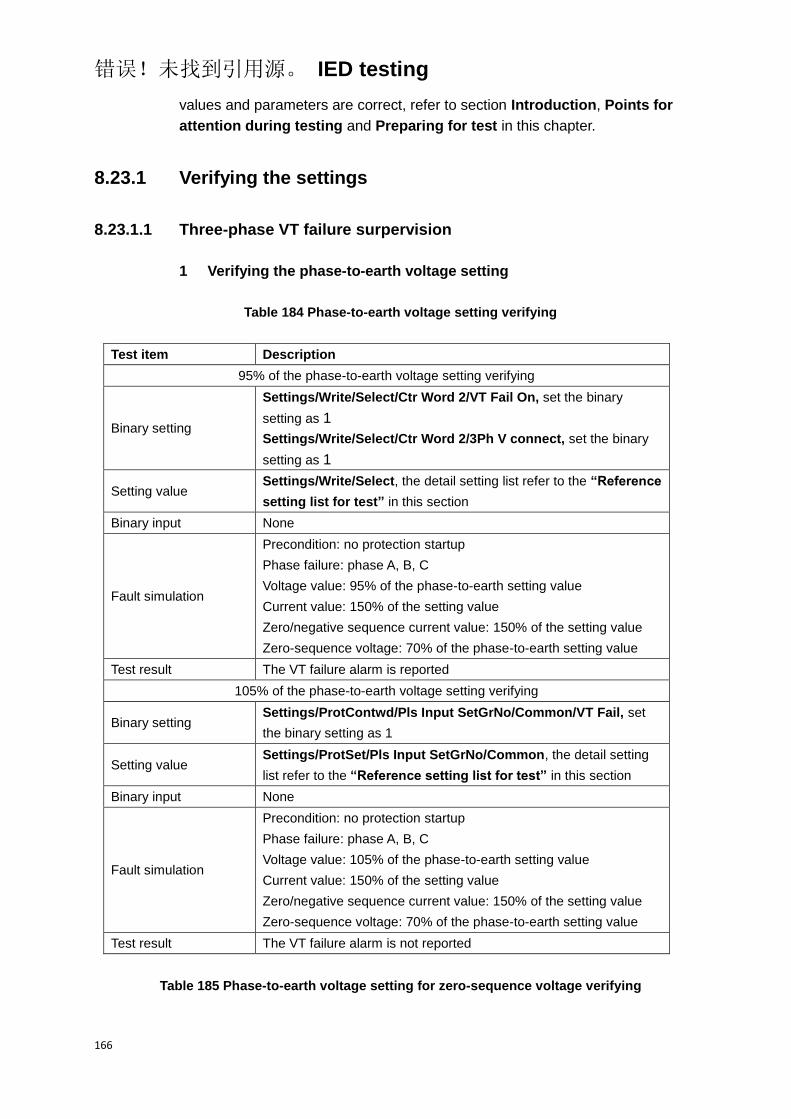
错误!未找到引用源。 IED testing
166
values and parameters are correct, refer to section Introduction, Points for
attention during testing and Preparing for test in this chapter.
8.23.1 Verifying the settings
8.23.1.1 Three-phase VT failure surpervision
1 Verifying the phase-to-earth voltage setting
Table 184 Phase-to-earth voltage setting verifying
Test item Description
95% of the phase-to-earth voltage setting verifying
Binary setting
Settings/Write/Select/Ctr Word 2/VT Fail On, set the binary
setting as 1
Settings/Write/Select/Ctr Word 2/3Ph V connect, set the binary
setting as 1
Setting value Settings/Write/Select, the detail setting list refer to the “Reference
setting list for test” in this section
Binary input None
Fault simulation
Precondition: no protection startup
Phase failure: phase A, B, C
Voltage value: 95% of the phase-to-earth setting value
Current value: 150% of the setting value
Zero/negative sequence current value: 150% of the setting value
Zero-sequence voltage: 70% of the phase-to-earth setting value
Test result The VT failure alarm is reported
105% of the phase-to-earth voltage setting verifying
Binary setting Settings/ProtContwd/Pls Input SetGrNo/Common/VT Fail, set
the binary setting as 1
Setting value Settings/ProtSet/Pls Input SetGrNo/Common, the detail setting
list refer to the “Reference setting list for test” in this section
Binary input None
Fault simulation
Precondition: no protection startup
Phase failure: phase A, B, C
Voltage value: 105% of the phase-to-earth setting value
Current value: 150% of the setting value
Zero/negative sequence current value: 150% of the setting value
Zero-sequence voltage: 70% of the phase-to-earth setting value
Test result The VT failure alarm is not reported
Table 185 Phase-to-earth voltage setting for zero-sequence voltage verifying
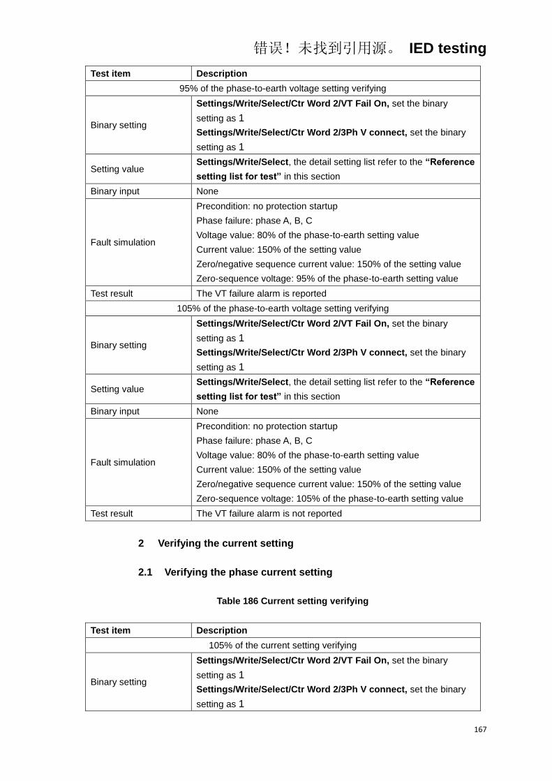
错误!未找到引用源。 IED testing
167
Test item Description
95% of the phase-to-earth voltage setting verifying
Binary setting
Settings/Write/Select/Ctr Word 2/VT Fail On, set the binary
setting as 1
Settings/Write/Select/Ctr Word 2/3Ph V connect, set the binary
setting as 1
Setting value Settings/Write/Select, the detail setting list refer to the “Reference
setting list for test” in this section
Binary input None
Fault simulation
Precondition: no protection startup
Phase failure: phase A, B, C
Voltage value: 80% of the phase-to-earth setting value
Current value: 150% of the setting value
Zero/negative sequence current value: 150% of the setting value
Zero-sequence voltage: 95% of the phase-to-earth setting value
Test result The VT failure alarm is reported
105% of the phase-to-earth voltage setting verifying
Binary setting
Settings/Write/Select/Ctr Word 2/VT Fail On, set the binary
setting as 1
Settings/Write/Select/Ctr Word 2/3Ph V connect, set the binary
setting as 1
Setting value Settings/Write/Select, the detail setting list refer to the “Reference
setting list for test” in this section
Binary input None
Fault simulation
Precondition: no protection startup
Phase failure: phase A, B, C
Voltage value: 80% of the phase-to-earth setting value
Current value: 150% of the setting value
Zero/negative sequence current value: 150% of the setting value
Zero-sequence voltage: 105% of the phase-to-earth setting value
Test result The VT failure alarm is not reported
2 Verifying the current setting
2.1 Verifying the phase current setting
Table 186 Current setting verifying
Test item Description
105% of the current setting verifying
Binary setting
Settings/Write/Select/Ctr Word 2/VT Fail On, set the binary
setting as 1
Settings/Write/Select/Ctr Word 2/3Ph V connect, set the binary
setting as 1
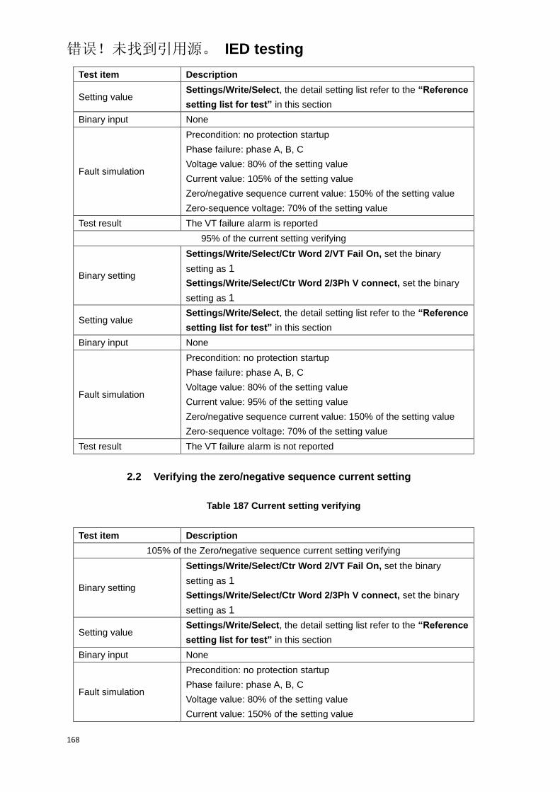
错误!未找到引用源。 IED testing
168
Test item Description
Setting value Settings/Write/Select, the detail setting list refer to the “Reference
setting list for test” in this section
Binary input None
Fault simulation
Precondition: no protection startup
Phase failure: phase A, B, C
Voltage value: 80% of the setting value
Current value: 105% of the setting value
Zero/negative sequence current value: 150% of the setting value
Zero-sequence voltage: 70% of the setting value
Test result The VT failure alarm is reported
95% of the current setting verifying
Binary setting
Settings/Write/Select/Ctr Word 2/VT Fail On, set the binary
setting as 1
Settings/Write/Select/Ctr Word 2/3Ph V connect, set the binary
setting as 1
Setting value Settings/Write/Select, the detail setting list refer to the “Reference
setting list for test” in this section
Binary input None
Fault simulation
Precondition: no protection startup
Phase failure: phase A, B, C
Voltage value: 80% of the setting value
Current value: 95% of the setting value
Zero/negative sequence current value: 150% of the setting value
Zero-sequence voltage: 70% of the setting value
Test result The VT failure alarm is not reported
2.2 Verifying the zero/negative sequence current setting
Table 187 Current setting verifying
Test item Description
105% of the Zero/negative sequence current setting verifying
Binary setting
Settings/Write/Select/Ctr Word 2/VT Fail On, set the binary
setting as 1
Settings/Write/Select/Ctr Word 2/3Ph V connect, set the binary
setting as 1
Setting value Settings/Write/Select, the detail setting list refer to the “Reference
setting list for test” in this section
Binary input None
Fault simulation
Precondition: no protection startup
Phase failure: phase A, B, C
Voltage value: 80% of the setting value
Current value: 150% of the setting value
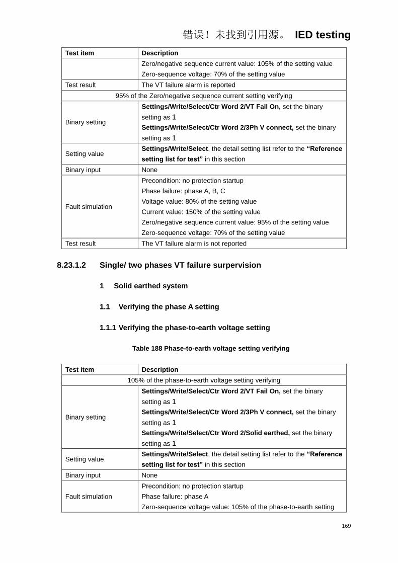
错误!未找到引用源。 IED testing
169
Test item Description
Zero/negative sequence current value: 105% of the setting value
Zero-sequence voltage: 70% of the setting value
Test result The VT failure alarm is reported
95% of the Zero/negative sequence current setting verifying
Binary setting
Settings/Write/Select/Ctr Word 2/VT Fail On, set the binary
setting as 1
Settings/Write/Select/Ctr Word 2/3Ph V connect, set the binary
setting as 1
Setting value Settings/Write/Select, the detail setting list refer to the “Reference
setting list for test” in this section
Binary input None
Fault simulation
Precondition: no protection startup
Phase failure: phase A, B, C
Voltage value: 80% of the setting value
Current value: 150% of the setting value
Zero/negative sequence current value: 95% of the setting value
Zero-sequence voltage: 70% of the setting value
Test result The VT failure alarm is not reported
8.23.1.2 Single/ two phases VT failure surpervision
1 Solid earthed system
1.1 Verifying the phase A setting
1.1.1 Verifying the phase-to-earth voltage setting
Table 188 Phase-to-earth voltage setting verifying
Test item Description
105% of the phase-to-earth voltage setting verifying
Binary setting
Settings/Write/Select/Ctr Word 2/VT Fail On, set the binary
setting as 1
Settings/Write/Select/Ctr Word 2/3Ph V connect, set the binary
setting as 1
Settings/Write/Select/Ctr Word 2/Solid earthed, set the binary
setting as 1
Setting value Settings/Write/Select, the detail setting list refer to the “Reference
setting list for test” in this section
Binary input None
Fault simulation
Precondition: no protection startup
Phase failure: phase A
Zero-sequence voltage value: 105% of the phase-to-earth setting

错误!未找到引用源。 IED testing
170
Test item Description
value
Test result The VT failure alarm is reported
95% of the phase-to-earth voltage setting verifying
Binary setting
Settings/Write/Select/Ctr Word 2/VT Fail On, set the binary
setting as 1
Settings/Write/Select/Ctr Word 2/3Ph V connect, set the binary
setting as 1
Settings/Write/Select/Ctr Word 2/Solid earthed, set the binary
setting as 1
Setting value Settings/Write/Select, the detail setting list refer to the “Reference
setting list for test” in this section
Binary input None
Fault simulation
Precondition: no protection startup
Phase failure: phase A
Zero-sequence voltage value: 95% of the phase-to-earth setting
value
Test result The VT failure alarm is not reported
1.2 Verifying the settings of other phase
The test method and test items of verifying the other phase are same as
phase A, only need to change the corresponding test conditions and settings
into the conrresponding other phase required.
2 Isolated system
2.1 Verifying the phase A setting
2.1.1 Verifying the phase-to-earth voltage setting
Table 189 Phase-to-earth voltage setting verifying
Test item Description
105% of the phase-to-earth voltage setting verifying
Binary setting
Settings/Write/Select/Ctr Word 2/VT Fail On, set the binary
setting as 1
Settings/Write/Select/Ctr Word 2/3Ph V connect, set the binary
setting as 1
Settings/Write/Select/Ctr Word 2/Isolate/Resist, set the binary
setting as 1
Setting value Settings/Write/Select, the detail setting list refer to the “Reference
setting list for test” in this section
Binary input None

错误!未找到引用源。 IED testing
171
Test item Description
Fault simulation
Precondition: no protection startup
Phase failure: phase A
Zero-sequence voltage value: 105% of the phase-to-earth setting
value
Max(Uab, Ubc, Uca) –Min(Uab, Ubc, Uca): 120% of the phase-to-phase
setting value
Test result The VT failure alarm is reported
95% of the phase-to-earth voltage setting verifying
Binary setting
Settings/Write/Select/Ctr Word 2/VT Fail On, set the binary
setting as 1
Settings/Write/Select/Ctr Word 2/3Ph V connect, set the binary
setting as 1
Settings/Write/Select/Ctr Word 2/Isolate/Resist, set the binary
setting as 1
Setting value Settings/Write/Select, the detail setting list refer to the “Reference
setting list for test” in this section
Binary input None
Fault simulation
Precondition: no protection startup
Phase failure: phase A
Zero-sequence voltage value: 95% of the phase-to-earth setting
value
Max(Uab, Ubc, Uca) –Min(Uab, Ubc, Uca): 120% of the phase-to-phase
setting value
Test result The VT failure alarm is not reported
2.1.2 Verifying the phase-to-phase voltage setting
Table 190 phase-to-phase voltage setting verifying
Test item Description
105% of the phase-to-phase voltage setting verifying
Binary setting
Settings/Write/Select/Ctr Word 2/VT Fail On, set the binary
setting as 1
Settings/Write/Select/Ctr Word 2/3Ph V connect, set the binary
setting as 1
Settings/Write/Select/Ctr Word 2/Isolate/Resist, set the binary
setting as 1
Setting value Settings/Write/Select, the detail setting list refer to the “Reference
setting list for test” in this section
Binary input None
Fault simulation
Precondition: no protection startup
Phase failure: phase A
Zero-sequence voltage value: 120% of the phase-to-earth setting
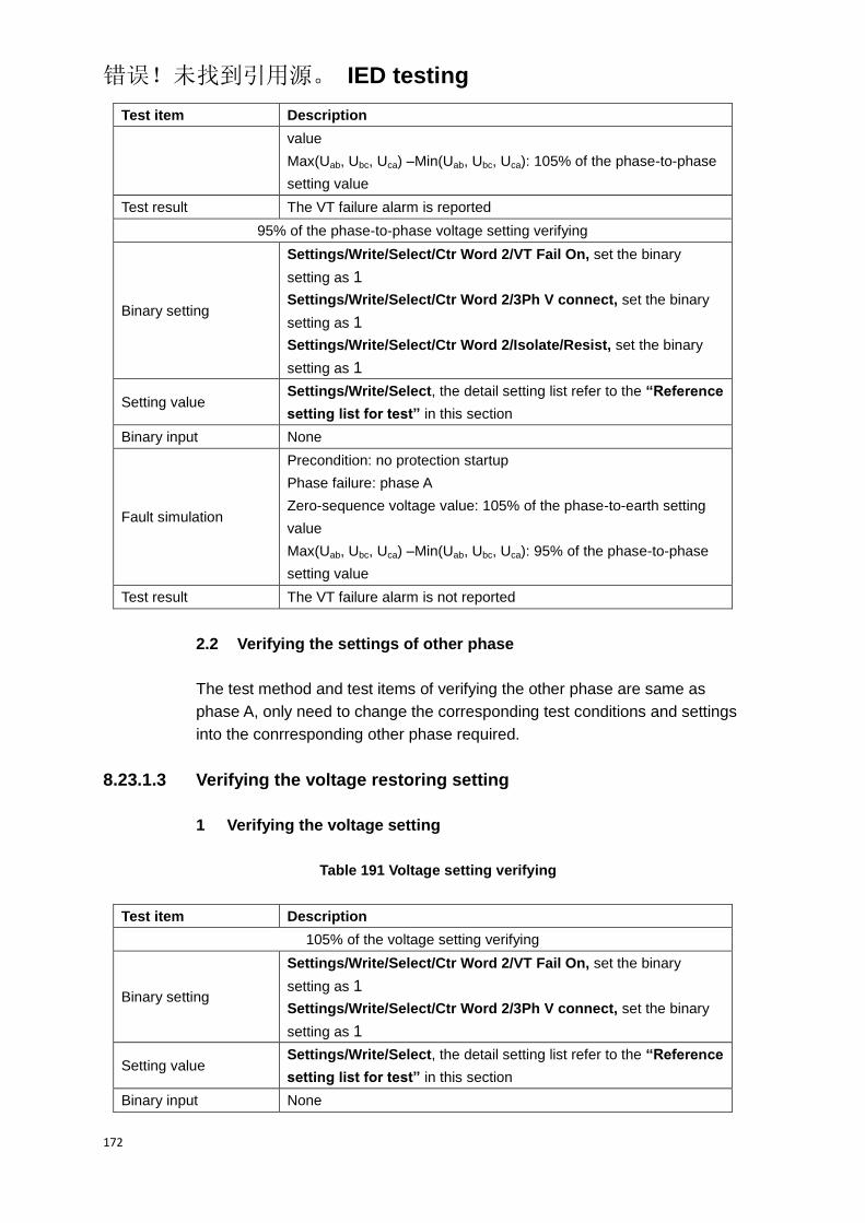
错误!未找到引用源。 IED testing
172
Test item Description
value
Max(Uab, Ubc, Uca) –Min(Uab, Ubc, Uca): 105% of the phase-to-phase
setting value
Test result The VT failure alarm is reported
95% of the phase-to-phase voltage setting verifying
Binary setting
Settings/Write/Select/Ctr Word 2/VT Fail On, set the binary
setting as 1
Settings/Write/Select/Ctr Word 2/3Ph V connect, set the binary
setting as 1
Settings/Write/Select/Ctr Word 2/Isolate/Resist, set the binary
setting as 1
Setting value Settings/Write/Select, the detail setting list refer to the “Reference
setting list for test” in this section
Binary input None
Fault simulation
Precondition: no protection startup
Phase failure: phase A
Zero-sequence voltage value: 105% of the phase-to-earth setting
value
Max(Uab, Ubc, Uca) –Min(Uab, Ubc, Uca): 95% of the phase-to-phase
setting value
Test result The VT failure alarm is not reported
2.2 Verifying the settings of other phase
The test method and test items of verifying the other phase are same as
phase A, only need to change the corresponding test conditions and settings
into the conrresponding other phase required.
8.23.1.3 Verifying the voltage restoring setting
1 Verifying the voltage setting
Table 191 Voltage setting verifying
Test item Description
105% of the voltage setting verifying
Binary setting
Settings/Write/Select/Ctr Word 2/VT Fail On, set the binary
setting as 1
Settings/Write/Select/Ctr Word 2/3Ph V connect, set the binary
setting as 1
Setting value Settings/Write/Select, the detail setting list refer to the “Reference
setting list for test” in this section
Binary input None
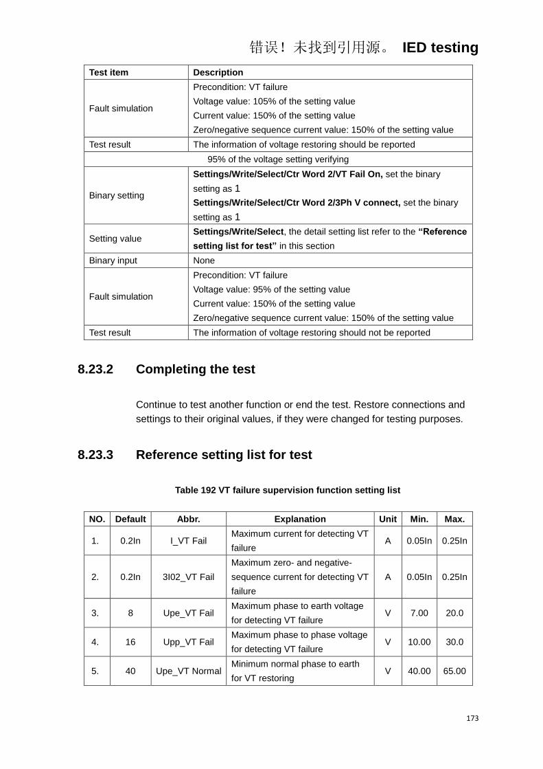
错误!未找到引用源。 IED testing
173
Test item Description
Fault simulation
Precondition: VT failure
Voltage value: 105% of the setting value
Current value: 150% of the setting value
Zero/negative sequence current value: 150% of the setting value
Test result The information of voltage restoring should be reported
95% of the voltage setting verifying
Binary setting
Settings/Write/Select/Ctr Word 2/VT Fail On, set the binary
setting as 1
Settings/Write/Select/Ctr Word 2/3Ph V connect, set the binary
setting as 1
Setting value Settings/Write/Select, the detail setting list refer to the “Reference
setting list for test” in this section
Binary input None
Fault simulation
Precondition: VT failure
Voltage value: 95% of the setting value
Current value: 150% of the setting value
Zero/negative sequence current value: 150% of the setting value
Test result The information of voltage restoring should not be reported
8.23.2 Completing the test
Continue to test another function or end the test. Restore connections and
settings to their original values, if they were changed for testing purposes.
8.23.3 Reference setting list for test
Table 192 VT failure supervision function setting list
NO. Default Abbr. Explanation Unit Min. Max.
1. 0.2In I_VT Fail Maximum current for detecting VT
failure A 0.05In 0.25In
2. 0.2In 3I02_VT Fail
Maximum zero- and negative-
sequence current for detecting VT
failure
A 0.05In 0.25In
3. 8 Upe_VT Fail Maximum phase to earth voltage
for detecting VT failure V 7.00 20.0
4. 16 Upp_VT Fail Maximum phase to phase voltage
for detecting VT failure V 10.00 30.0
5. 40 Upe_VT Normal Minimum normal phase to earth
for VT restoring V 40.00 65.00

错误!未找到引用源。 IED testing
174
Table 193 VT failure supervision function setting list
Bit Default “0” “1” Explanation
2.9 0 3Ph V Connect 1Ph V Connect Single phase or three phase
voltage connection
2.10 0 Isolate/ Resist Solid earthed Solid earthed system or
isolated system
2.15 1 VT Fail Off VT Fail On Enable or disable the function
of VT failure
8.24 Monitoring function
8.24.1 Auxiliary contact of circuit breaker monitoring
Before starting the test, please make sure that the protection function setting
values and parameters are correct, refer to section Introduction, Points for
attention during testing and Preparing for test in this chapter.
8.24.1.1 Testing the function
1 Checking the auxiliary contact of CB of phase A
Table 194 Auxiliary contact of circuit breaker verifying
Test item Description
Binary setting None
Setting value None
Binary input The position of phase A of circuit breaker is “Off”
Fault simulation Current: input the rated current into the phase A
Test result The alarm is issued
2 Checking the auxiliary contact of CB of other phase
The test method of checking the other phase are same as phase A, only need
to change the corresponding test conditions into the conrresponding other
phase required.
8.24.1.2 Completing the test
Continue to test another function or end the test. Restore connections and
settings to their original values, if they were changed for testing purposes.

错误!未找到引用源。 IED testing
175
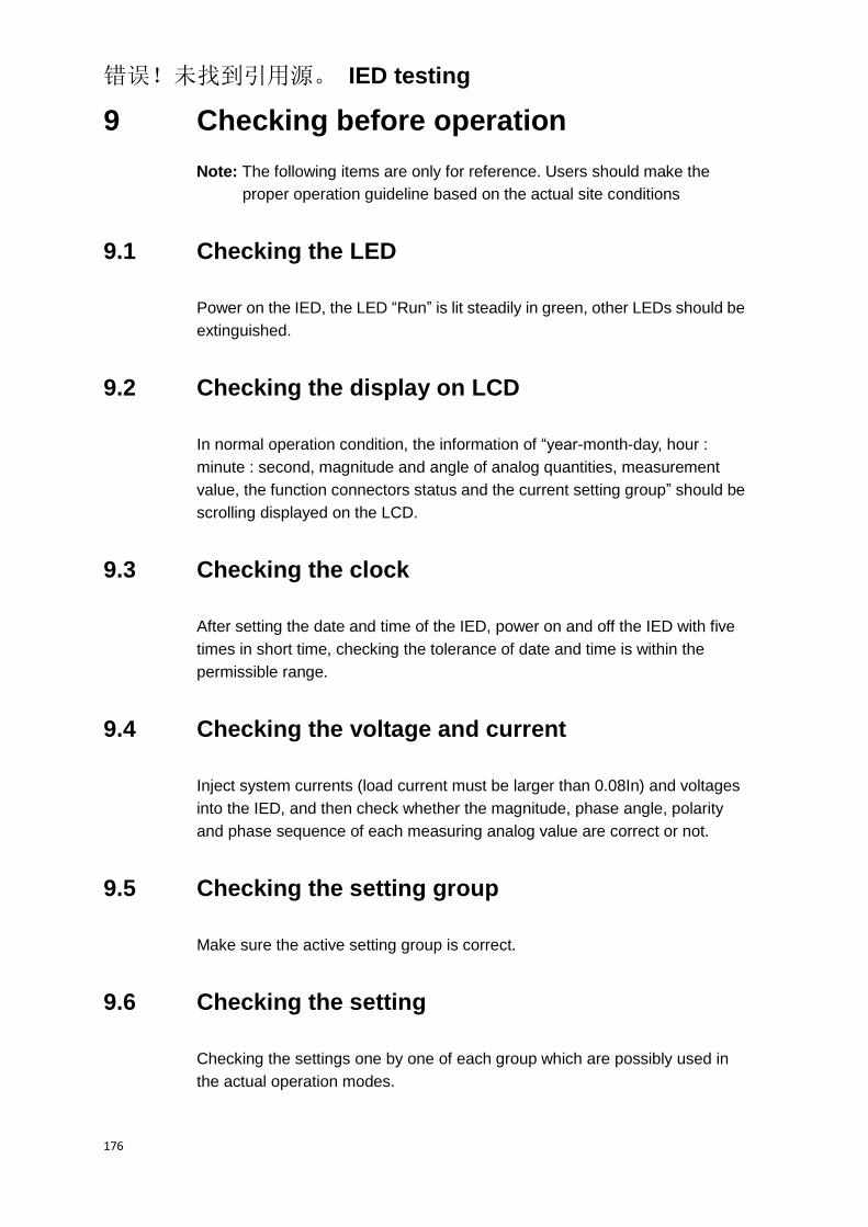
错误!未找到引用源。 IED testing
176
9 Checking before operation
Note: The following items are only for reference. Users should make the
proper operation guideline based on the actual site conditions
9.1 Checking the LED
Power on the IED, the LED “Run” is lit steadily in green, other LEDs should be
extinguished.
9.2 Checking the display on LCD
In normal operation condition, the information of “year-month-day, hour :
minute : second, magnitude and angle of analog quantities, measurement
value, the function connectors status and the current setting group” should be
scrolling displayed on the LCD.
9.3 Checking the clock
After setting the date and time of the IED, power on and off the IED with five
times in short time, checking the tolerance of date and time is within the
permissible range.
9.4 Checking the voltage and current
Inject system currents (load current must be larger than 0.08In) and voltages
into the IED, and then check whether the magnitude, phase angle, polarity
and phase sequence of each measuring analog value are correct or not.
9.5 Checking the setting group
Make sure the active setting group is correct.
9.6 Checking the setting
Checking the settings one by one of each group which are possibly used in
the actual operation modes.

错误!未找到引用源。 IED testing
177
9.7 Checking the binary input
Check the state of all binary inputs. Particularly ensure that the IED is not in
test mode, meaning that the green “Run” LED is not flash continuously
9.8 Checking the normal operation mode
9.8.1 Trip and close test with the circuit breaker
9.8.1.1 Switching the circuit breaker state by local command
Trip and close the circuit breaker, the corresponding feedback state of circuit
breaker injected via binary inputs should be read out and compared with the
actual state of circuit breaker, the displayed state should be in accordance
with the actual state.
9.8.1.2 Switching the circuit breaker state from remote control center
If the IED is connected to a remote substation via SCADA, the corresponding
switching tests may also be checked from the substation.
9.9 Put into operation
If all the checking items described above and the other checking items need to be
performed according to the site condition have been checked and correct, the IED can be
put into operation.

错误!未找到引用源。 IED testing
178

错误!未找到引用源。 Operating maintenance
179
Chapter 7 Operating maintenance
About this chapter
This chapter introduces attentions and the required checking,
operation after updating software or replacing modules and the
measure for alarm information.
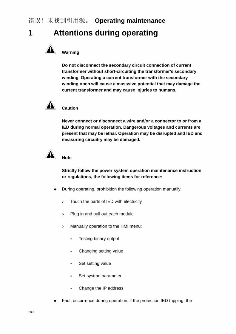
错误!未找到引用源。 Operating maintenance
180
1 Attentions during operating
Warning
Do not disconnect the secondary circuit connection of current
transformer without short-circuiting the transformer's secondary
winding. Operating a current transformer with the secondary
winding open will cause a masssive potential that may damage the
current transformer and may cause injuries to humans.
Caution
Never connect or disconnect a wire and/or a connector to or from a
IED during normal operation. Dangerous voltages and currents are
present that may be lethal. Operation may be disrupted and IED and
measuring circuitry may be damaged.
Note
Strictly follow the power system operation maintenance instruction
or regulations, the following items for reference:
During operating, prohibition the following operation manually:
Touch the parts of IED with electricity
Plug in and pull out each module
Manually operation to the HMI menu:
Testing binary output
Changing setting value
Set setting value
Set systme parameter
Change the IP address
Fault occurrence during operation, if the protection IED tripping, the
错误!未找到引用源。 Operating maintenance
181
corresponding LED in front panel will be lighted, and the event reports
will be displayed in HMI; if the autoreclosure function operate, the
corresponding LED will be lighted and the reports will be displayed in
HMI
If the alarming class I appearance during operation, stop running the IED,
record the alarm information and inform the responsible engineer, at this
time, it is not allowed to press the Reset button. If the alarming class II
appearance, record the alarm information and inform the responsible
engineer to analyse and deal with.

错误!未找到引用源。 Operating maintenance
182
2 Routine checking
Checking the LEDs status
Checking scroll display information in HMI
Checking the setting group number

错误!未找到引用源。 Operating maintenance
183
3 Periodical checking
Check that the inside and outside of the IED are cleanly and no ash
deposition
All components (including the chips, transformer and relay, etc.) of the
IED are fixed well, no loosing phenomenon, the IED apperance is regular
and no damage and distortion phenomenon
The buttons are operated flexibly with good feeling and fixed reliably
All the IED terminals for connection are firmd without loosing
phenomenon, and the marked number are clear and correct
Energizing the IED with DC power supply for several seconds, the green
“Run” LED and protection function LED that connector have been
enabled will be lighted without any alarm or operation lED lighted (if
lighted, press Reset button to reset), the analog quantities is displayed in
HMI
Check the zero drift and scale
Check the operation setting values
Measure the output voltage of power supply
Check the alarm circuit
Check the binary input
Check the tripping and closing circuit
Test the insulation resistance
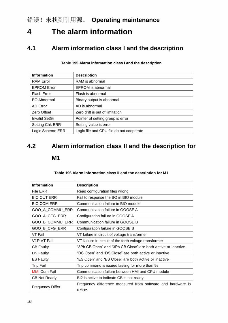
错误!未找到引用源。 Operating maintenance
184
4 The alarm information
4.1 Alarm information class I and the description
Table 195 Alarm information class I and the description
Information Description
RAM Error RAM is abnormal
EPROM Error EPROM is abnormal
Flash Error Flash is abnormal
BO Abnormal Binary output is abnormal
AD Error AD is abnormal
Zero Offset Zero drift is out of limitation
Invalid SetGr Pointer of setting group is error
Setting Chk ERR Setting value is error
Logic Scheme ERR Logic file and CPU file do not cooperate
4.2 Alarm information class II and the description for
M1
Table 196 Alarm information class II and the description for M1
Information Description
File ERR Read configuration files wrong
BIO OUT ERR Fail to response the BO in BIO module
BIO COM ERR Communication failure in BIO module
GOO_A_COMMU_ERR Communication failure in GOOSE A
GOO_A_CFG_ERR Configuration failure in GOOSE A
GOO_B_COMMU_ERR Communication failure in GOOSE B
GOO_B_CFG_ERR Configuration failure in GOOSE B
VT Fail VT failure in circuit of voltage transformer
V1P VT Fail VT failure in circuit of the forth voltage transformer
CB Faulty “3Ph CB Open” and “3Ph CB Close” are both active or inactive
DS Faulty “DS Open” and “DS Close” are both active or inactive
ES Faulty “ES Open” and “ES Close” are both active or inactive
Trip Fail Trip command is issued lasting for more than 9s
MMI Com Fail Communication failure between HMI and CPU module
CB Not Ready BI2 is active to indicate CB is not ready
Frequency Differ Frequency difference measured from software and hardware is
0.5Hz

错误!未找到引用源。 Operating maintenance
185
Information Description
OC1 Alarm Overcurrent protection stage 1 issues an alarm signal
OC Inv Alarm Overcurrent protection inverse stage issues an alarm signal
EF1 Alarm Earth fault protection stage 1 issues an alarm signal
EF Inv Alarm Earth fault protection inverse stage issues an alarm signal
NSOC1 Alarm Negative sequence overcurrent protection stage 1 issues an alarm
signal
NSOC Inv Alarm Negative sequence overcurrent protection inverse stage issues an
alarm signal
SEF1 Alarm Sensitive earth fault protection stage 1 issues an alarm signal
SEF2 Alarm Sensitive earth fault protection stage 2 issues an alarm signal
SEF Inv Alarm Sensitive earth fault protection inverse stage issues an alarm signal
3V01 Alarm Displacement Voltage protection stage 1 issues an alarm signal
3V02 Alarm Displacement Voltage protection stage 2 issues an alarm signal
PhA Grounded Phase A is grounded
PhB Grounded Phase B is grounded
PhC Grounded Phase C is grounded
UV1 Alarm Undervoltage protection stage 1 issues an alarm signal
OV1 Alarm Overvoltage protection stage 1 issues an alarm signal
Therm OL Alarm Thermal overload protection issues an alarm signal
CT Fail Failure in circuit of current transformer
BI Set SetGr2 Setting group switches to 1 when binary input is 0
BI Set SetGr1 Setting group switches to 2 when binary input is 1
Table 197 Alarm information class II and the description for M6
Information Description
File ERR Read configuration files wrong
BIO OUT ERR Fail to response the BO in BIO module
BIO COM ERR Communication failure in BIO module
GOO_A_COMMU_ERR Communication failure in GOOSE A
GOO_A_CFG_ERR Configuration failure in GOOSE A
GOO_B_COMMU_ERR Communication failure in GOOSE B
GOO_B_CFG_ERR Configuration failure in GOOSE B
CB Faulty “3Ph CB Open” and “3Ph CB Close” are both active or inactive
DS Faulty “DS Open” and “DS Close” are both active or inactive
ES Faulty “ES Open” and “ES Close” are both active or inactive
Trip Fail Trip command is issued lasting for more than 9s
MMI Com Fail Communication failure between HMI and CPU module
Frequency Differ Frequency difference measured from software and hardware is
0.5Hz
OC1 Alarm Overcurrent protection stage 1 issues an alarm signal
OC Inv Alarm Overcurrent protection inverse stage issues an alarm signal

错误!未找到引用源。 Operating maintenance
186
Information Description
EF1 Alarm Earth fault protection stage 1 issues an alarm signal
EF Inv Alarm Earth fault protection inverse stage issues an alarm signal
SEF1 Alarm Sensitive earth fault protection stage 1 issues an alarm signal
SEF2 Alarm Sensitive earth fault protection stage 2 issues an alarm signal
SEF Inv Alarm Sensitive earth fault protection inverse stage issues an alarm signal
CT Fail Failure in circuit of current transformer
BI Set SetGr2 Setting group switches to 1 when binary input is 0
BI Set SetGr1 Setting group switches to 2 when binary input is 1
Table 198 Alarm information class II and the description for C1
Information Description
File ERR Read configuration files wrong
BIO OUT ERR Fail to response the BO in BIO module
BIO COM ERR Communication failure in BIO module
GOO_A_COMMU_ERR Communication failure in GOOSE A
GOO_A_CFG_ERR Configuration failure in GOOSE A
GOO_B_COMMU_ERR Communication failure in GOOSE B
GOO_B_CFG_ERR Configuration failure in GOOSE B
VT Fail VT failure in circuit of voltage transformer
V1p VT Fail VT failure in circuit of the forth voltage transformer
CB Faulty “3Ph CB Open” and “3Ph CB Close” are both active or inactive
DS Faulty “DS Open” and “DS Close” are both active or inactive
ES Faulty “ES Open” and “ES Close” are both active or inactive
Trip Fail Trip command is issued lasting for more than 9s
MMI Com Fail Communication failure between HMI and CPU module
Frequency Differ Frequency difference measured from software and hardware is
0.5Hz
OC1 Alarm Overcurrent protection stage 1 issues an alarm signal
OC Inv Alarm Overcurrent protection inverse stage issues an alarm signal
EF1 Alarm Earth fault protection stage 1 issues an alarm signal
EF Inv Alarm Earth fault protection inverse stage issues an alarm signal
SEF1 Alarm Sensitive earth fault protection stage 1 issues an alarm signal
SEF2 Alarm Sensitive earth fault protection stage 2 issues an alarm signal
SEF Inv Alarm Sensitive earth fault protection inverse stage issues an alarm signal
3V01 Alarm Displacement Voltage protection stage 1 issues an alarm signal
3V02 Alarm Displacement Voltage protection stage 2 issues an alarm signal
PhA Grounded Phase A is grounded
PhB Grounded Phase B is grounded
PhC Grounded Phase C is grounded
UV1 Alarm Undervoltage protection stage 1 issues an alarm signal
OV1 Alarm Overvoltage protection stage 1 issues an alarm signal
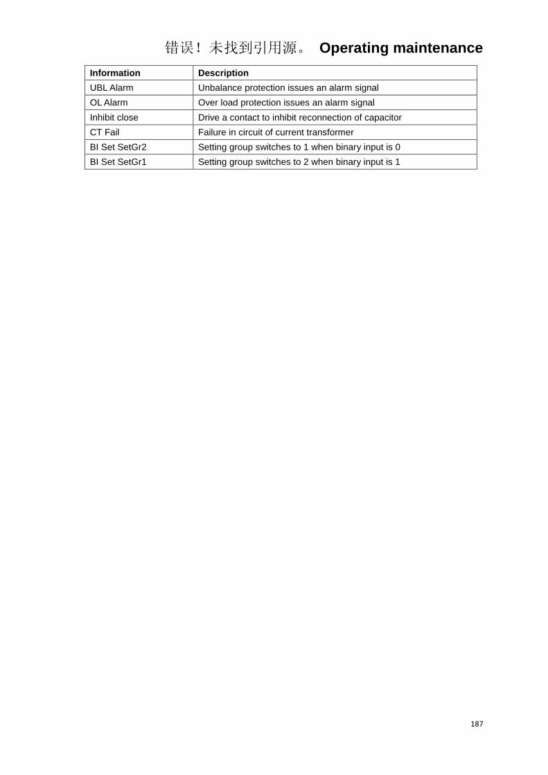
错误!未找到引用源。 Operating maintenance
187
Information Description
UBL Alarm Unbalance protection issues an alarm signal
OL Alarm Over load protection issues an alarm signal
Inhibit close Drive a contact to inhibit reconnection of capacitor
CT Fail Failure in circuit of current transformer
BI Set SetGr2 Setting group switches to 1 when binary input is 0
BI Set SetGr1 Setting group switches to 2 when binary input is 1

错误!未找到引用源。 Operating maintenance
188

错误!未找到引用源。 Transportation and storage
189
Chapter 8 Transportation and storage
About this chapter
This chapter describes how to transport and store the IED.

错误!未找到引用源。 Transportation and storage
190
1 Transportion
The IED can be transported by means of conveyance, such as car, train, ship, etc. In order to ensure the perfect performance of the IED, prevent the IED from rain, snow, vibration, shock and bump.

错误!未找到引用源。 Transportation and storage
191
2 Storage
If the IED is to be stored before installation, this is must be done in the original
transport casing in a dry and dust free place. The packed IED should be
stored in a waterproof and snow proof place without acid or alkaline or other
corrosive gas and explosive gas. The storage temperature is from -25°C to
+40°C, and the relative humidity does not exceed 80%. Observe the
environmental requirements stated in the technical data.

错误!未找到引用源。 Transportation and storage
192

Chapter 9 Appendix
193
Chapter 9 Appendix
About this chapter
This chapter contains the diagram of modules arrangement,
typical connection, glossary and the protocol data table.

Chapter 9 Appendix
194
1 Arrangement diagram of modules
X1
AIM
X2
AIM
X3
BIO
X4
CPU
X5
FIO
X6
FOM
X7
PSM
Figure 15 The arrangement diagram of modules
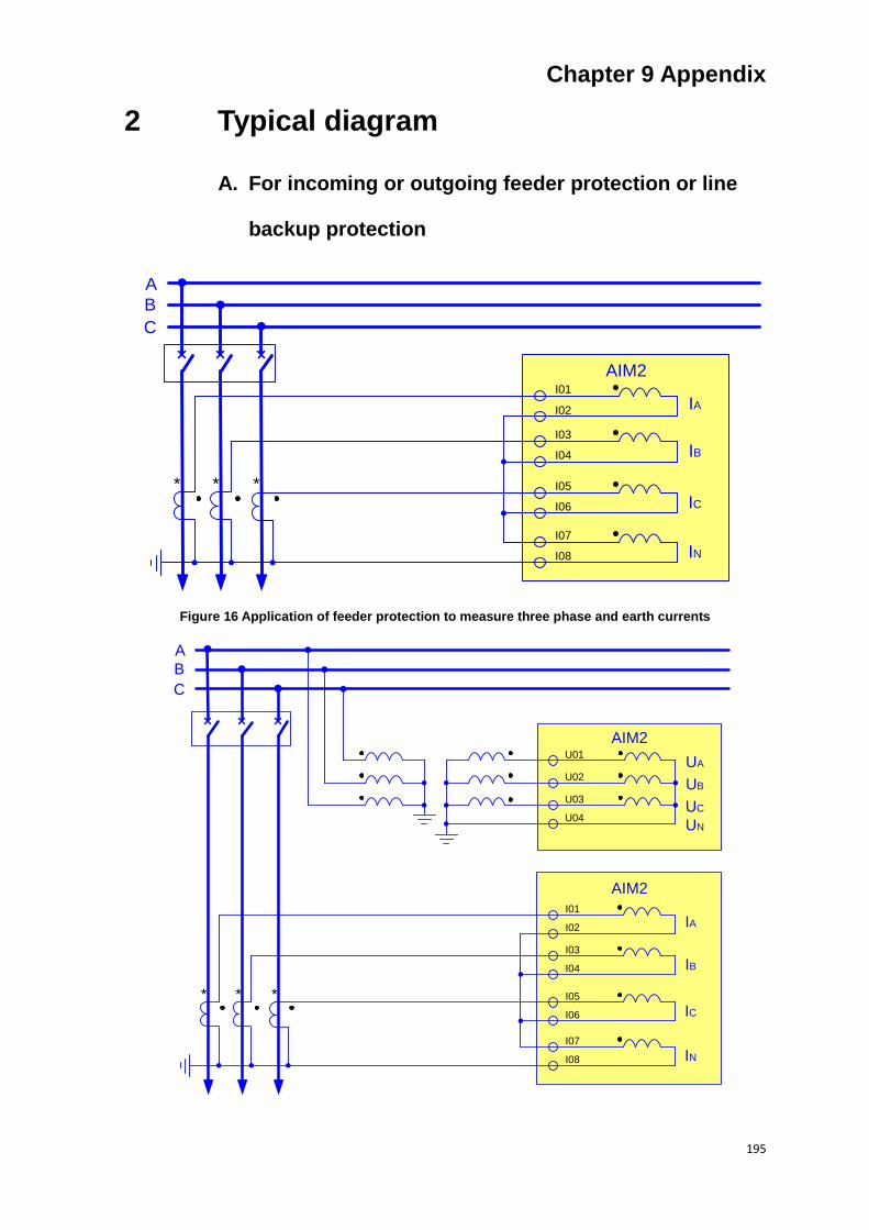
Chapter 9 Appendix
195
2 Typical diagram
A. For incoming or outgoing feeder protection or line
backup protection
IA
IB
IC
IN
AIM2
A
B
C
* * *
I01
I03
I05
I07
I02
I04
I06
I08
Figure 16 Application of feeder protection to measure three phase and earth currents
IA
IB
IC
UB
UA
UC
IN
UN
AIM2
A
B
C
* * *
I01
I03
I05
I07
I02
I04
I06
I08
U01
U02
U03
U04
AIM2

Chapter 9 Appendix
196
Figure 17 Application of feeder protection to measure three phase and earth currents and three phase
voltages (bus side)
IA
IB
IC
UB
UA
UC
IN
UN
AIM2
A
B
C
* * *
I01
I03
I05
I07
I02
I04
I06
I08
U01
U02
U03
U04
AIM2
Figure 18 Application of feeder protection to measure three phase and earth currents and three phase
voltages (line side)

Chapter 9 Appendix
197
IA
IB
IC
UB
UA
UC
IN
UN
AIM2
A
B
C
* * *
I01
I03
I05
I07
I02
I04
I06
I08
U01
U03
AIM2
U02
U04
Figure 19 Application of feeder protection to measure three phase and earth currents and single phase
voltage (Ph-Ph) (bus side)

Chapter 9 Appendix
198
IA
IB
IC
UB
UA
UC
IN
UN
AIM2
A
B
C
* * *
I01
I03
I05
I07
I02
I04
I06
I08
U01
U03
AIM2
U02
U04
Figure 20 Application of feeder protection to measure three phase and earth currents and single phase
voltage (Ph-E) (bus side)
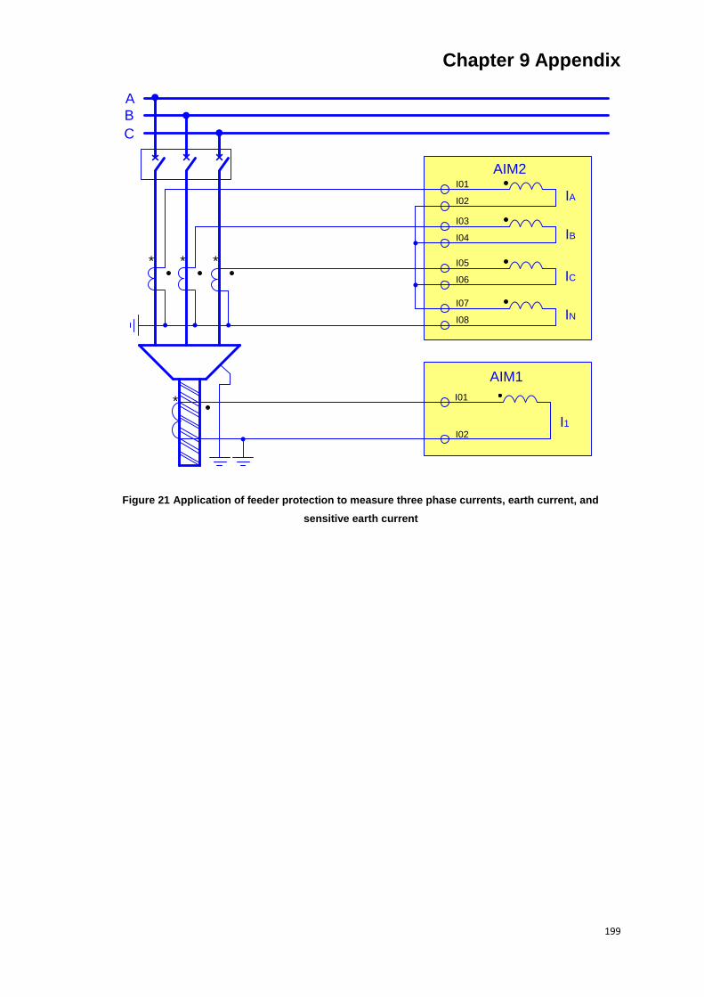
Chapter 9 Appendix
199
IA
IB
IC
IN
AIM2
A
B
C
* * *
I01
I03
I05
I07
I02
I04
I06
I08
I01
AIM1
I02
*
I1
Figure 21 Application of feeder protection to measure three phase currents, earth current, and
sensitive earth current

Chapter 9 Appendix
200
IA
IB
IC
IN
AIM2
A
B
C
* * *
I01
I03
I05
I07
I02
I04
I06
I08
I01
AIM1
I02
*
UB
UA
UC
UN
U01
U02
U03
U04
AIM2
I1
Figure 22 Application of feeder protection to measure three phase currents, earth current and sensitive
earth current, and three phase voltages (bus side)
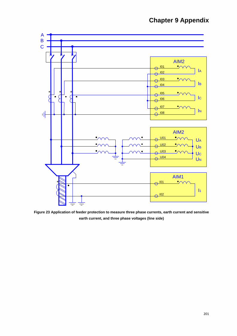
Chapter 9 Appendix
201
IA
IB
IC
IN
AIM2
A
B
C
* * *
I01
I03
I05
I07
I02
I04
I06
I08
I01
AIM1
I02
*
UB
UA
UC
UN
U01
U02
U03
U04
AIM2
I1
Figure 23 Application of feeder protection to measure three phase currents, earth current and sensitive
earth current, and three phase voltages (line side)
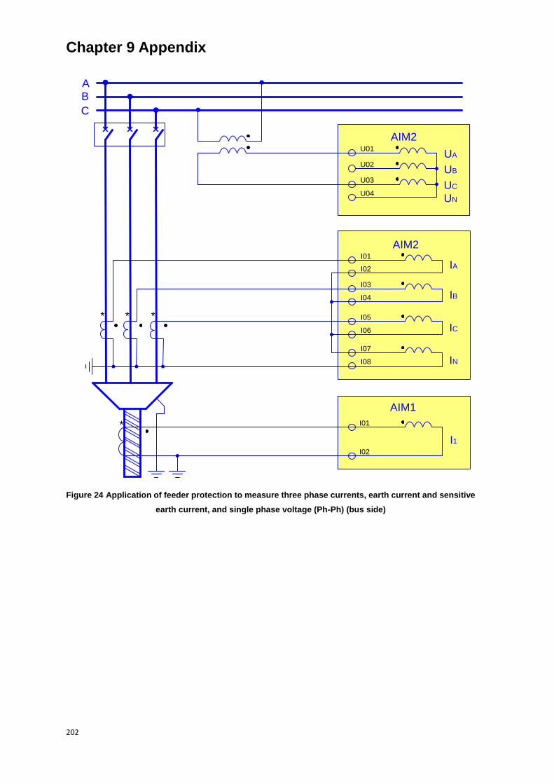
Chapter 9 Appendix
202
IA
IB
IC
IN
AIM2
A
B
C
* * *
I01
I03
I05
I07
I02
I04
I06
I08
I01
AIM1
I02
*
UB
UA
UC
UN
U01
U02
U03
U04
AIM2
I1
Figure 24 Application of feeder protection to measure three phase currents, earth current and sensitive
earth current, and single phase voltage (Ph-Ph) (bus side)
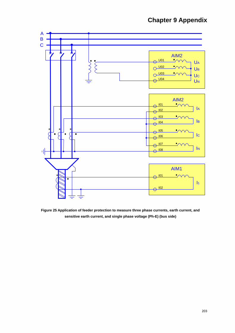
Chapter 9 Appendix
203
IA
IB
IC
IN
AIM2
A
B
C
* * *
I01
I03
I05
I07
I02
I04
I06
I08
I01
AIM1
I02
*
UB
UA
UC
UN
U01
U02
U03
U04
AIM2
I1
Figure 25 Application of feeder protection to measure three phase currents, earth current, and
sensitive earth current, and single phase voltage (Ph-E) (bus side)
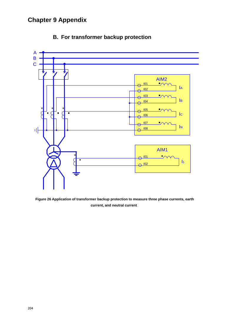
Chapter 9 Appendix
204
B. For transformer backup protection
IA
IB
IC
IN
AIM2
A
B
C
* * *
I01
I03
I05
I07
I02
I04
I06
I08
I01
AIM1
I02I1
*
Figure 26 Application of transformer backup protection to measure three phase currents, earth
current, and neutral current

Chapter 9 Appendix
205
IA
IB
IC
IN
AIM2
A
B
C
* * *
I01
I03
I05
I07
I02
I04
I06
I08
I01
AIM1
I02 I1
UB
UA
UC
UN
U01
U02
U03
U04
AIM2
*
Figure 27 Application of transformer backup protection to measure three phase currents, earth current
and neutral current, and three phase voltages (bus side)
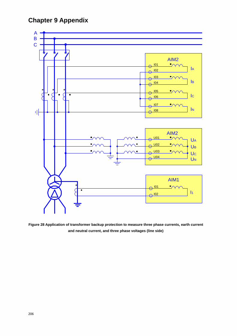
Chapter 9 Appendix
206
IA
IB
IC
IN
AIM2
A
B
C
* * *
I01
I03
I05
I07
I02
I04
I06
I08
I01
AIM1
I02 I1
UB
UA
UC
UN
U01
U02
U03
U04
AIM2
*
Figure 28 Application of transformer backup protection to measure three phase currents, earth current
and neutral current, and three phase voltages (line side)

Chapter 9 Appendix
207
IA
IB
IC
IN
AIM2
A
B
C
* * *
I01
I03
I05
I07
I02
I04
I06
I08
I01
AIM1
I02 I1
UB
UA
UC
UN
U01
U02
U03
U04
AIM2
*
Figure 29 Application of transformer backup protection to measure three phase currents, earth current
and neutral current, and single phase voltage (Ph-Ph) (bus side)
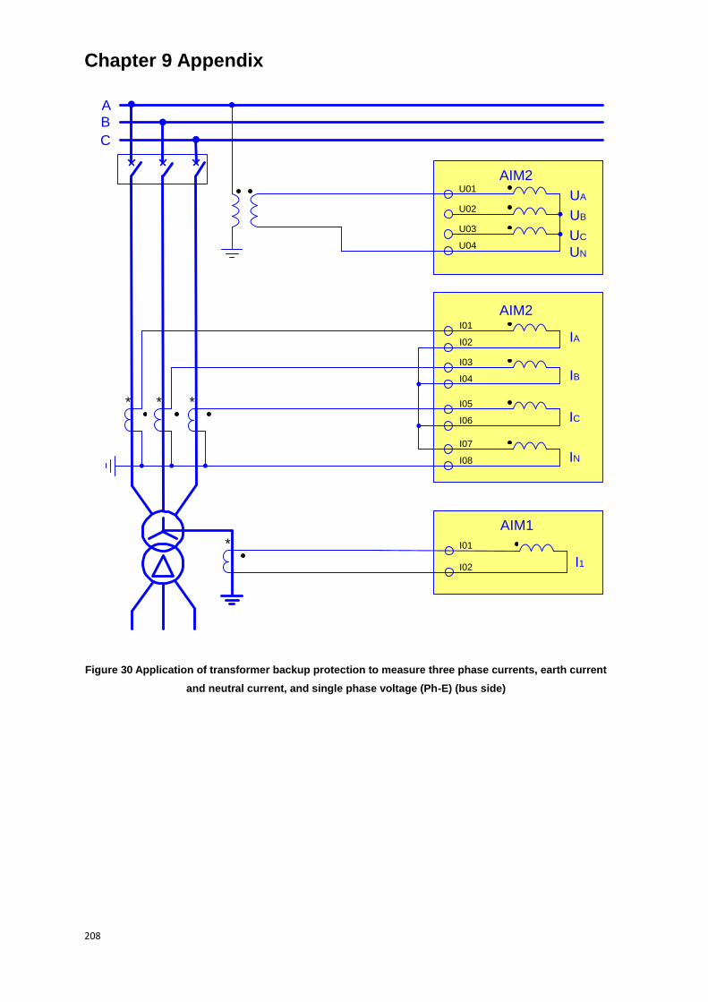
Chapter 9 Appendix
208
IA
IB
IC
IN
AIM2
A
B
C
* * *
I01
I03
I05
I07
I02
I04
I06
I08
I01
AIM1
I02 I1
UB
UA
UC
UN
U01
U02
U03
U04
AIM2
*
Figure 30 Application of transformer backup protection to measure three phase currents, earth current
and neutral current, and single phase voltage (Ph-E) (bus side)

Chapter 9 Appendix
209
C. For synch-check function
A
B
C
UB
UA
UC
UN
U01
U02
U03
U04
AIM2
U4
U05
U06
A
B
C
Figure 31 Typical connection for synch-check on bus coupler applications
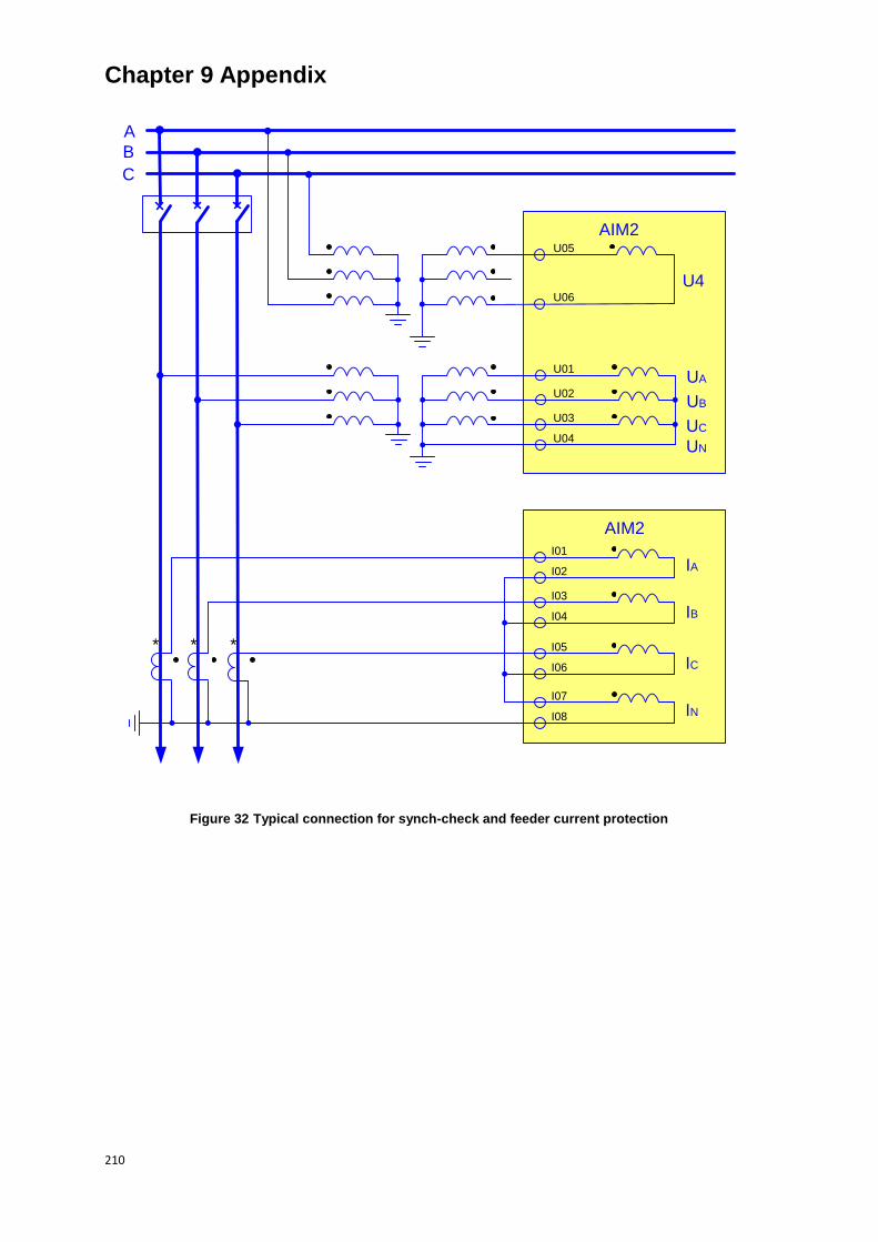
Chapter 9 Appendix
210
IA
IB
IC
IN
AIM2
A
B
C
* * *
I01
I03
I05
I07
I02
I04
I06
I08
UB
UA
UC
UN
U01
U02
U03
U04
AIM2
U4
U05
U06
Figure 32 Typical connection for synch-check and feeder current protection
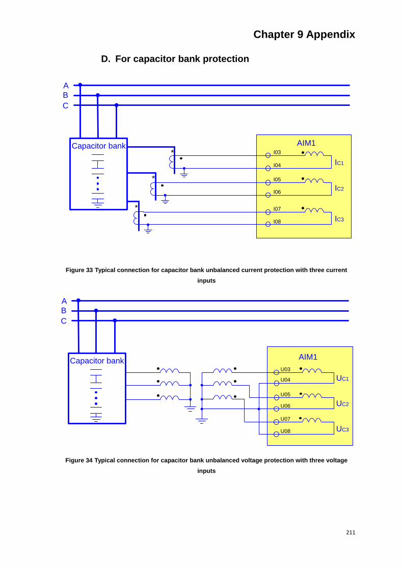
Chapter 9 Appendix
211
D. For capacitor bank protection
A
B
C
Capacitor bank
IC1
IC2
IC3
AIM1
*
*
* I03
I05
I07
I04
I06
I08
Figure 33 Typical connection for capacitor bank unbalanced current protection with three current
inputs
A
B
C
Capacitor bank
UC1
U03
U05
U07
AIM1
U04
U06
U08
UC2
UC3
Figure 34 Typical connection for capacitor bank unbalanced voltage protection with three voltage
inputs
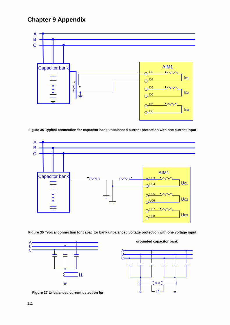
Chapter 9 Appendix
212
A
B
C
Capacitor bank
*IC1
IC2
IC3
AIM1I03
I05
I07
I04
I06
I08
Figure 35 Typical connection for capacitor bank unbalanced current protection with one current input
UC1
A
B
C
U03
U05
U07
AIM1Capacitor bank
U04
U06
U08
UC2
UC3
Figure 36 Typical connection for capacitor bank unbalanced voltage protection with one voltage input
I1
ABC
Figure 37 Unbalanced current detection for
grounded capacitor bank
I1
ABC
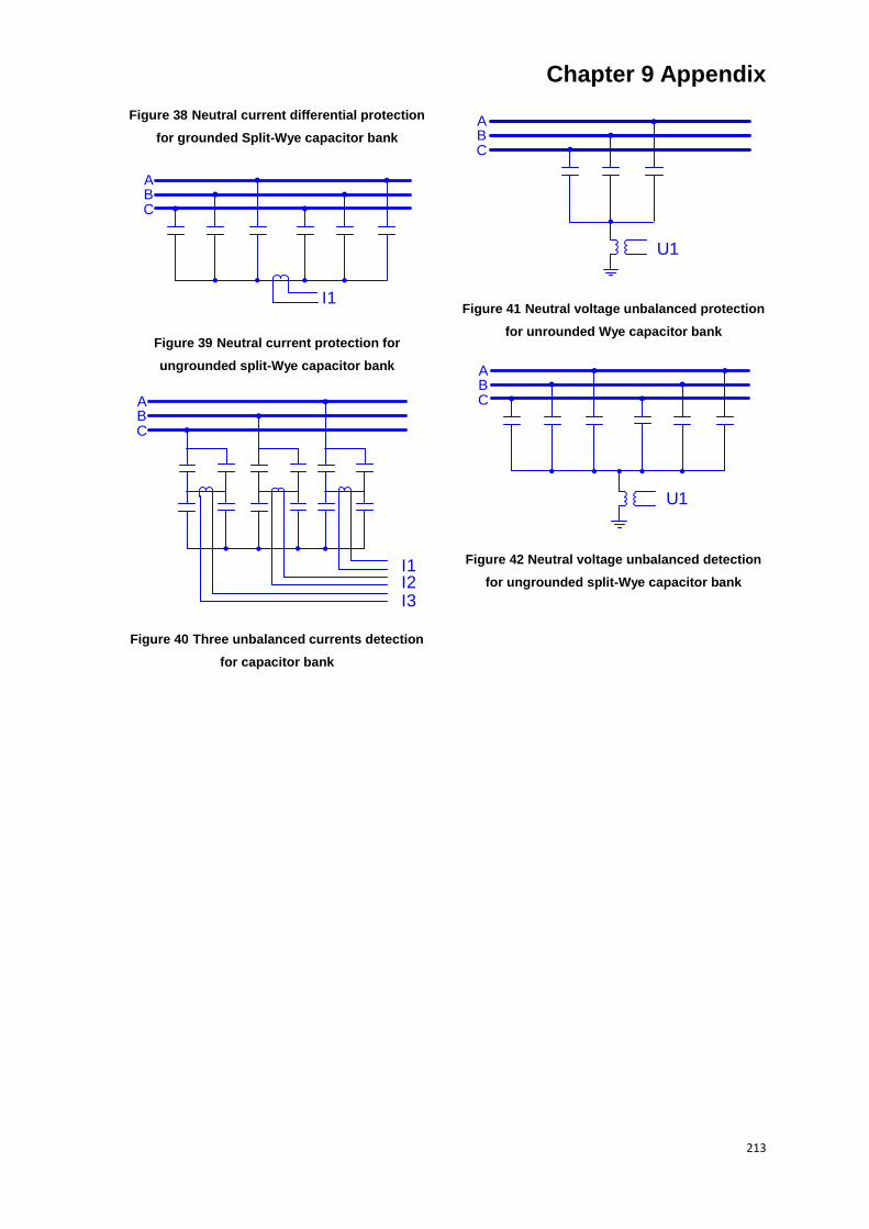
Chapter 9 Appendix
213
Figure 38 Neutral current differential protection
for grounded Split-Wye capacitor bank
I1
ABC
Figure 39 Neutral current protection for
ungrounded split-Wye capacitor bank
I1I2I3
ABC
Figure 40 Three unbalanced currents detection
for capacitor bank
U1
ABC
Figure 41 Neutral voltage unbalanced protection
for unrounded Wye capacitor bank
U1
ABC
Figure 42 Neutral voltage unbalanced detection
for ungrounded split-Wye capacitor bank
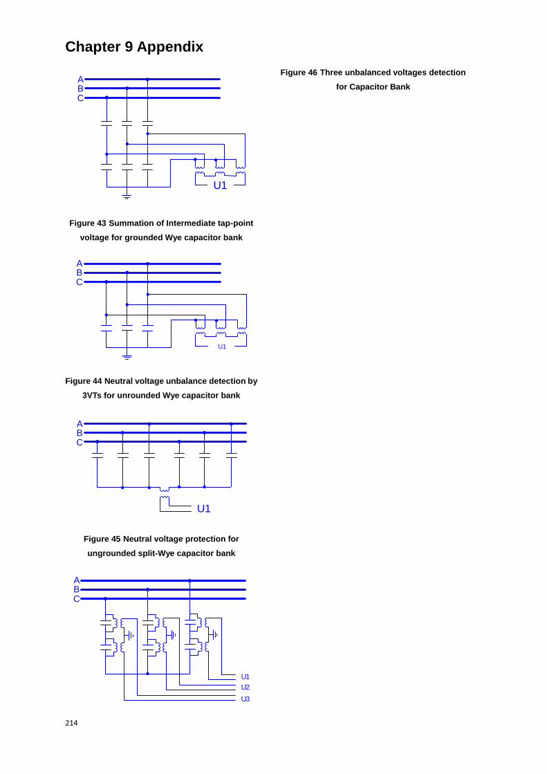
Chapter 9 Appendix
214
U1
ABC
Figure 43 Summation of Intermediate tap-point
voltage for grounded Wye capacitor bank
U1
ABC
Figure 44 Neutral voltage unbalance detection by
3VTs for unrounded Wye capacitor bank
U1
ABC
Figure 45 Neutral voltage protection for
ungrounded split-Wye capacitor bank
U1
U2
U3
ABC
Figure 46 Three unbalanced voltages detection
for Capacitor Bank
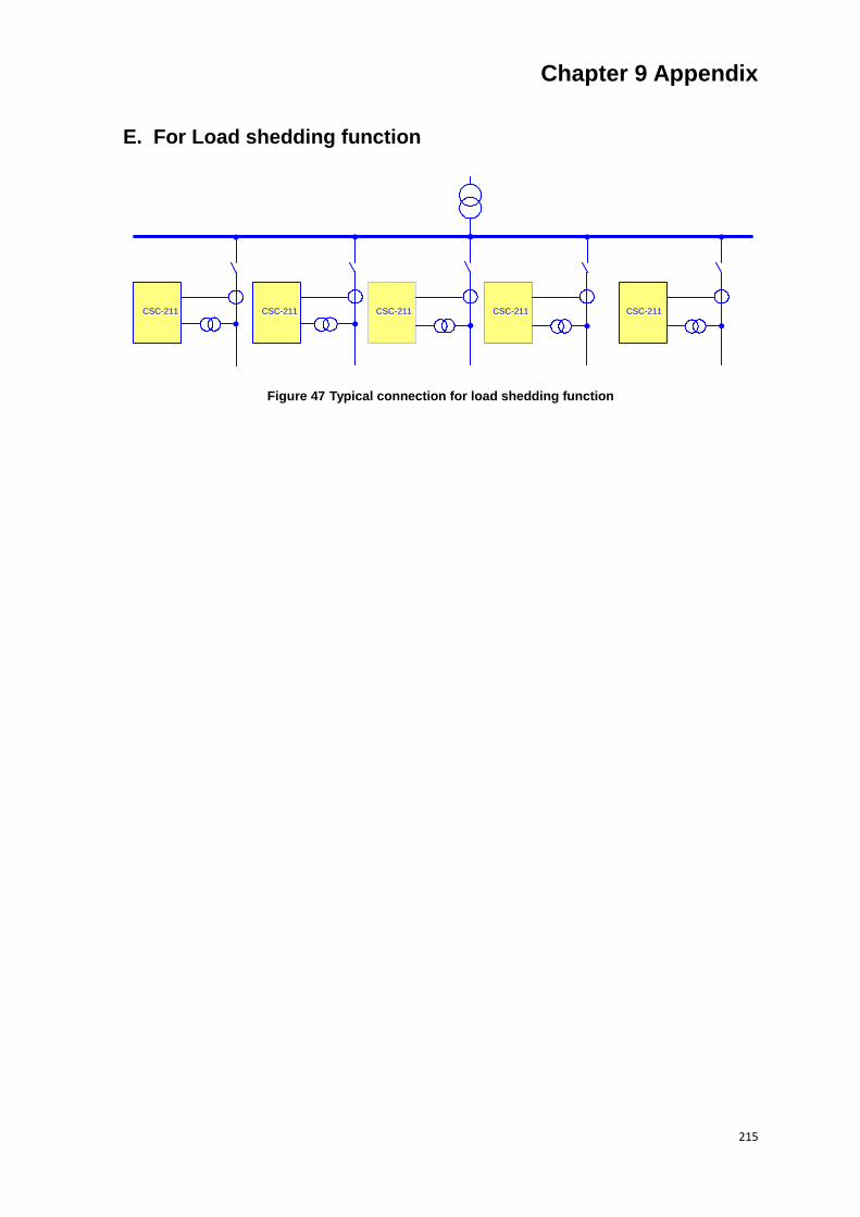
Chapter 9 Appendix
215
E. For Load shedding function
CSC-211 CSC-211 CSC-211 CSC-211 CSC-211
Figure 47 Typical connection for load shedding function