cs380: computer graphics ray tracing
TRANSCRIPT
CS380: Computer GraphicsRay Tracing
Sung-Eui Yoon(윤성의)
Course URL:http://sglab.kaist.ac.kr/~sungeui/CG/

2
Class Objectives●Understand overall algorithm of recursive
ray tracing● Ray generations● Intersection tests and acceleration methods● Basic sampling methods

3
Various Visibility Algorithm● Scan-line algorithm; briefly touched before● Z-buffer ●Ray casting, etc.

4
Ray Casting
● For each pixel, find closest object along the ray and shade pixel accordingly
● Advantages● Conceptually simple● Can be extended to handle global
illumination effects
●Disadvantages● Renderer must have access to entire retained model● Hard to map to special-purpose hardware● Less efficient than rasterization in terms of utilizing spatial
coherence

5
Recursive Ray Casting●Ray casting generally dismissed early on
because of aforementioned problems
●Gained popularity in whenTurner Whitted (1980) showed this image● Show recursive
ray casting could be usedfor global illumination effects

6
Ray Casting and Ray Tracing● Trace rays from eye into scene
● Backward ray tracing●Ray casting used to compute visibility at
the eye● Perform ray tracing for arbitrary rays
needed for shading● Reflections● Refraction and transparency● Shadows

7
Basic Algorithms of Ray Tracing●Rays are cast from the eye point through
each pixel in the image
From kavita’s slides

8
Shadows● Cast ray from the intersection point to each
light source● Shadow rays
From kavita’s slides

9
Reflections● If object specular, cast secondary reflected
rays
From kavita’s slides

10
Refractions● If object tranparent, cast secondary
refracted rays
From kavita’s slides

11
An Improved Illumination Model [Whitted 80]● Phong model
●Whitted model
● S and T are intensity of light from reflection and transmission rays
● Ks and Kt are specular and transmission coefficient
numLights
1j
njs
jsj
jd
jd
ja
jar ))RV(Ik)LN(IkI(kI sˆˆˆˆ
TkSk))LN(IkI(kI ts1j
jjd
jd
ja
jar
e_Lightsnum_Visiblˆˆ

12
An Improved Illumination Model [Whitted 80]
TkSk))LN(IkI(kI ts
numLights
1jj
jd
jd
ja
jar
ˆˆ
Computing reflection and transmitted/refracted rays is based on Snell’s law (refer to Chapter 13.1)

13
Ray Tree
eye
s0
b
a
dc
fe
s1s2
eye
a bs0
e fs2 c bs1
R T
R R TT

14
Overall Algorithm of Ray Tracing● Per each pixel, compute a ray, R
Def function RayTracing (R)● Compute an intersection against objects● If no hit,
● Return the background color●Otherwise,
● Compute shading, c● General secondary ray, R’● Perform c’ = RayTracing (R’)● Return c+c’

15
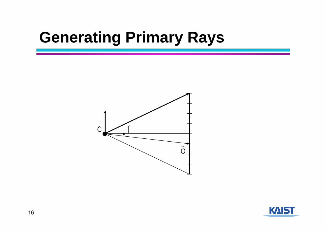
Ray Representation●We need to compute the first surface hit
along a ray● Represent ray with origin and direction● Compute intersections of objects with ray● Return the closest object
p(t ) o td
pd
o
16
Generating Primary Rays
l
d
o

17
Generating Secondary Rays● The origin is the intersection point p0
●Direction depends on the type of ray● Shadow rays – use direction to the light source● Reflection rays – use incoming direction and
normal to compute reflection direction● Transparency/refraction – use snell’s law

18
Intersection TestsGo through all of the objects in the scene to
determine the one closest to the origin of the ray (the eye).
Strategy: Solve of the intersection of the Ray with a mathematical description of the object

19
Simple Strategy● Parametric ray equation
● Gives all points along the ray as a function of the parameter
● Implicit surface equation● Describes all points on the surface as the zero
set of a function
● Substitute ray equation into surface function and solve for t
p(t ) o td
0)p(f
0)dto(f

20
Ray-Plane Intersection●Implicit equation of a plane:
●Substitute ray equation:
●Solve for t:
n p d 0
n (o td) d 0
t (n d) d n o
d n ot
n d

21
Generalizing to Triangles● Find of the point of intersection on the plane
containing the triangle● Determine if the point is inside the triangle
● Barycentric coordinate method● Many other methods
v1
v2v3p
o

22
Barycentric Coordinates● Points in a triangle have positive
barycentric coordinates:v1
v2v3p
)()( 02010 vvvvvp
210)1( vvvp
210 vvvp 1 ,where
v0v1
v2
p

23
Barycentric Coordinates● Points in a triangle have positive
barycentric coordinates:
● Benefits:● Barycentric coordinates can be used for interpolating
vertex parameters (e.g., normals, colors, texture coordinates, etc)
v1
v2v3p
210 vvvp 1 ,where

24
Ray-Triangle Intersection● A point in a ray intersects with a triangle
● Three unknowns, but three equations● Compute the point based on t● Then, check whether the point is on the
triangle● Refer to Sec. 4.4.2 in the textbook for the detail
equations
v1
v2v3p
)()()( 02010 vvvvvtp

25
Robustness Issues● False self-intersections
● One solution is to offset the origin of the ray from the surface when tracing secondary rays
Secondary ray

26
Pros and Cons of Ray TracingAdvantages of Ray Tracing: ● Very simple design ● Improved realism over
the graphics pipeline
Disadvantages: ● Very slow per pixel calculations ● Only approximates full global illumination ● Hard to accelerate with special-purpose H/W

27
Acceleration Methods● Rendering time for a ray tracer depends on the
number of ray intersection tests per pixel● The number of pixels X the number of primitives in the scene
● Early efforts focused on accelerating the ray-object intersection tests
● More advanced methods required to make ray tracing practical● Bounding volume hierarchies● Spatial subdivision

28
Bounding Volumes● Enclose complex objects within a simple-to-
intersect objects● If the ray does not intersect the simple object then its contents
can be ignored
● The likelihood that it will strike the object depends on how tightly the volume surrounds the object.
Potentially tighter fit, but with higher computation

29
Hierarchical Bounding Volumes●Organize bounding volumes as a tree● Each ray starts with the root BV of the tree
and traverses down through the tree
r
30
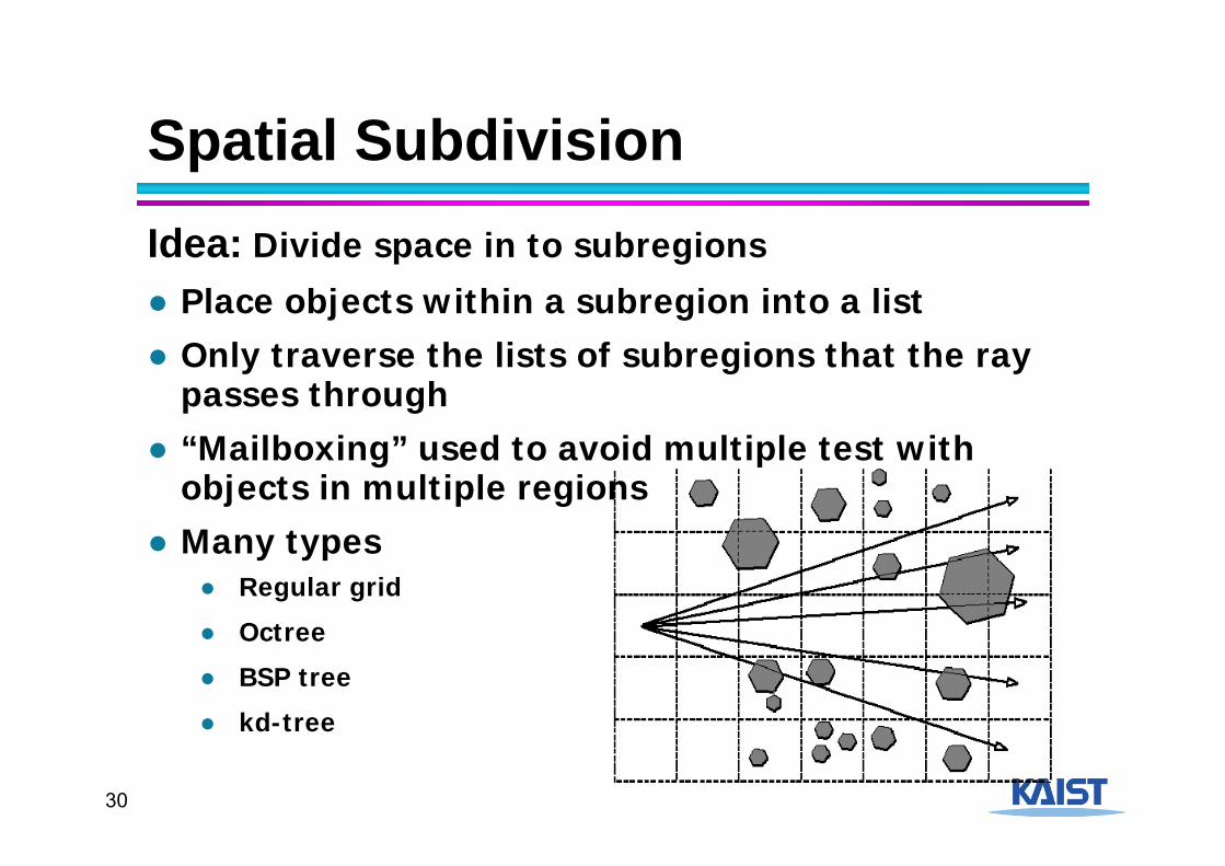
Spatial SubdivisionIdea: Divide space in to subregions
● Place objects within a subregion into a list ● Only traverse the lists of subregions that the ray
passes through ● “Mailboxing” used to avoid multiple test with
objects in multiple regions● Many types
● Regular grid
● Octree
● BSP tree
● kd-tree

31
Kd-tree: Example

32
Kd-tree: Example

33
Kd-tree: Example

34
Example

35
Kd-tree: Example
What about triangles overlapping the split?

36
Kd-tree: Example
37
Split Planes●How to select axis & split plane?
● Largest dimension, subdivide in middle● More advanced:
●Surface area heuristic
●Makes large difference● 50%-100% higher overall speed

38
Median vs. SAH
(from [Wald04])
39
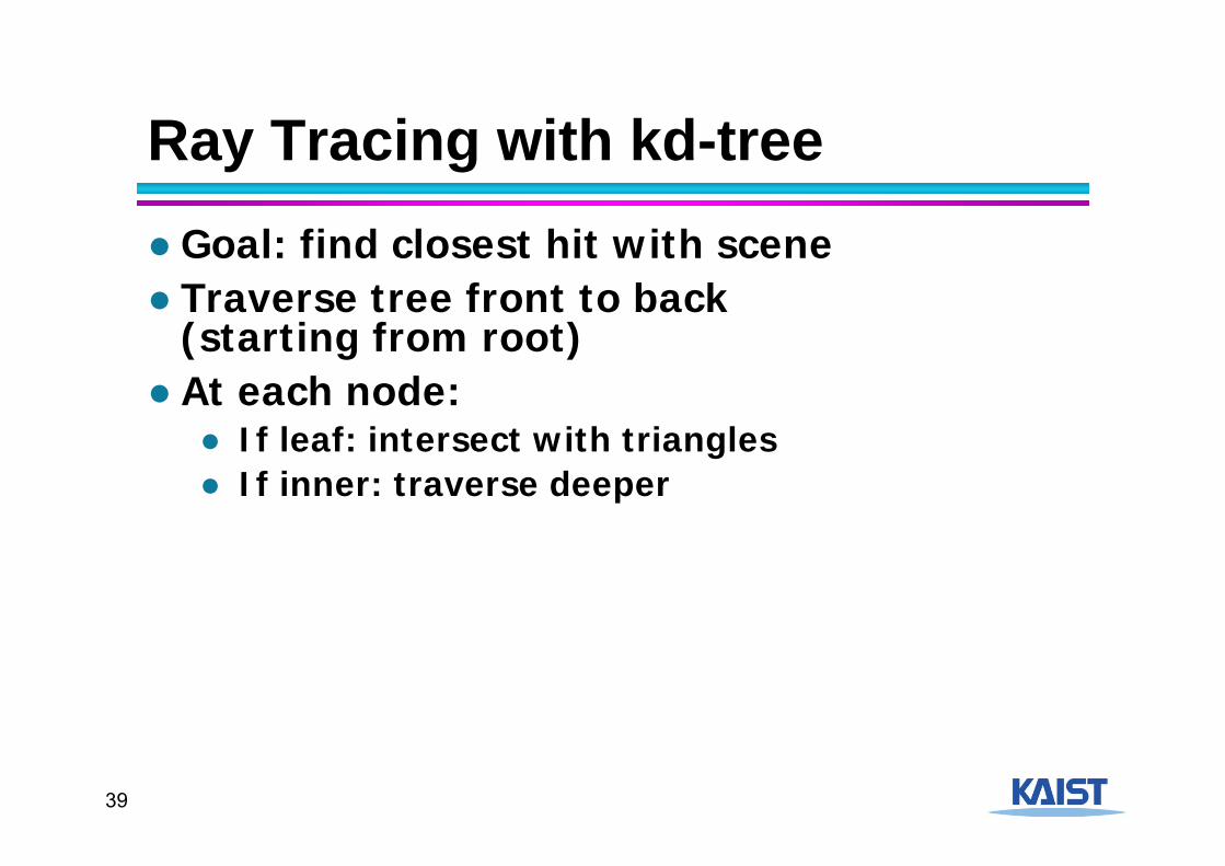
Ray Tracing with kd-tree●Goal: find closest hit with scene● Traverse tree front to back
(starting from root)● At each node:
● If leaf: intersect with triangles ● If inner: traverse deeper
40
Other Optimizations● Shadow cache● Adaptive depth control● Lazy geometry loading/creation

41
Distributed Ray Tracing [Cook et al. 84]● Cook et al. realized that ray-tracing, when
combined with randomized sampling, which they called “jittering”, could be adapted to address a wide range of rendering problems:

42
Soft Shadows● Take many samples from area light source
and take their average● Computes fractional visibility leading to
penumbra

43
Antialiasing● The need to sample is problematic because
sampling leads to aliasing● Solution 1: super-sampling
● Increases sampling rate, but does not completely eliminate aliasing
● Difficult to completely eliminate aliasing without prefiltering because the world is not band-limited

44
Antialiasing● Solution 2: distribute the samples randomly
● Converts the aliasing energy to noise which is less objectionable to the eye
Instead of casting one ray per pixel, cast several sub- sampling.
Instead of uniform sub-sampling, jitter the pixels slightly off the grid.

45
Jittering Results for Antialiasing
2x2 sub-sampling

46
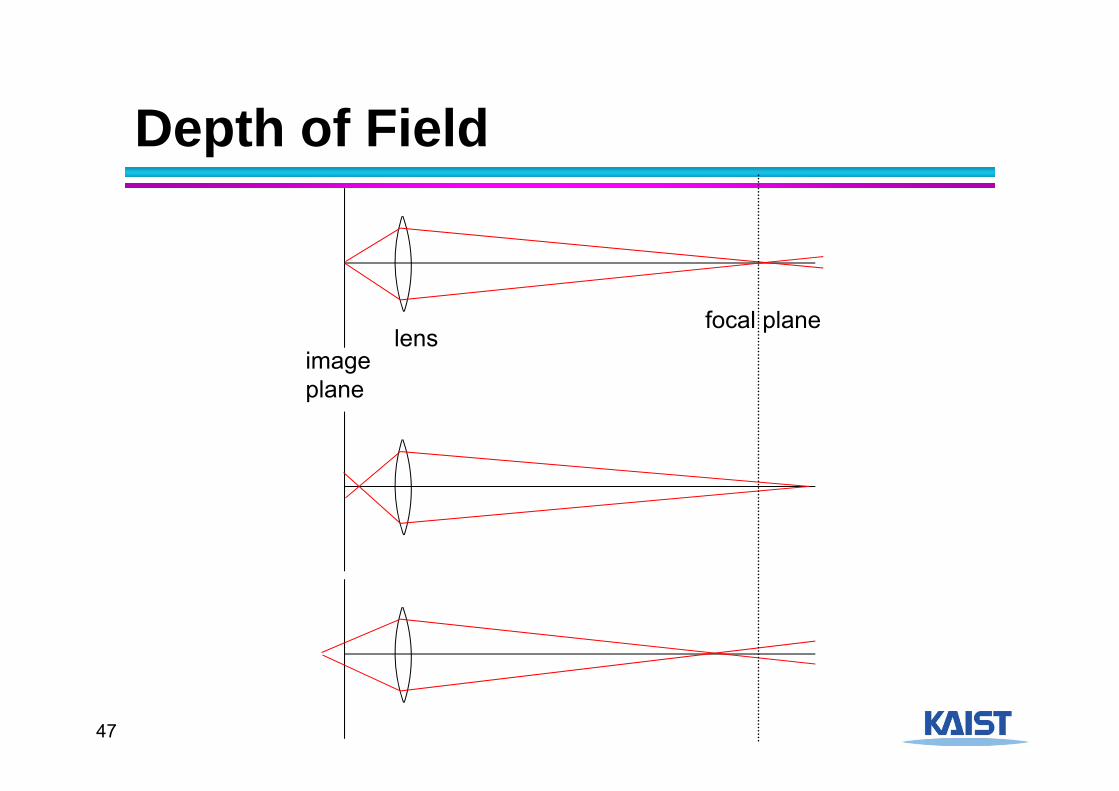
Depth-of-Field● Rays don’t have to all originate from a single point.● Real cameras collects rays over an aperture
● Can be modeled as a disk
● Final image is blurred away from the focal plane
● Gives rise to depth-of-field effects
47
Depth of Field
lensimageplane
focal plane

48
Depth of Field● Start with normal eye ray and find
intersection with focal plane● Choose jittered point on lens and trace line
from lens point to focal point
lensfocal plane

49
Motion Blur
● Jitter samples through time● Simulate the finite interval that a shutter is
open on a real camera

50
Motion Blur

51
Complex Interreflection● Model true reflection behavior as described by a full
BRDF ● Randomly sample rays over the hemisphere, weight
them by their BRDF value, and average them together● This technique is called “Monte Carlo Integration”
52
Related Courses● CS580: Advanced Computer Graphics
● Focus on rendering techniques that generate photo-realistic images
● CS482: Interactive Computer Graphics● Interactive global illumination implemented by
rasterization approaches● Techniques used in recent games● I’ll teach it at Fall of 2015