cs3000 users manual - weighsouth.com manual intercomp co. 3839 county road 116 ... service...
TRANSCRIPT
Page 1 of 35
CS3000™ Users Manual
Intercomp Co. 3839 County Road 116
Medina, MN 55340
(763)-476-2531 1-800-328-3336
Fax: 763-476-2613 www.intercompcompany.c
Manual#: 700435-A

CS3000, Users Rev A, January, 2011
Page 2 of 35
Table of Contents INTRODUCTION .......................................................................................................................................................4
SPECIFICATIONS.........................................................................................................................................................4 Controls ...............................................................................................................................................................4 Electrical..............................................................................................................................................................4 Performance.........................................................................................................................................................4 Environmental......................................................................................................................................................4 Radio....................................................................................................................................................................4 Physical................................................................................................................................................................5
WEIGHTS AND MEASURES .........................................................................................................................................6 PARTS AND OPTIONAL EQUIPMENT ...........................................................................................................................6
OPERATIONS.............................................................................................................................................................7 DISPLAY ....................................................................................................................................................................7 CONTROLS.................................................................................................................................................................7
ON / OFF .............................................................................................................................................................7 ACCUM / TOTAL ................................................................................................................................................7 MODE..................................................................................................................................................................7 ZERO ...................................................................................................................................................................8 Lb/Kg ...................................................................................................................................................................8 TARE....................................................................................................................................................................8
MODE MENU .............................................................................................................................................................9 SETTING THE MODE MENU PARAMETERS..................................................................................................................9 ACCUM / TOTAL USE ...............................................................................................................................................13
Accumulation Errors..........................................................................................................................................13 MOTION DETECTION SYSTEM ..................................................................................................................................13
SERIAL OUTPUT (OPTIONAL)............................................................................................................................14 Print Output Examples.......................................................................................................................................14
SCOREBOARD ..........................................................................................................................................................15 MAINTENANCE ......................................................................................................................................................18
CALIBRATION MENU ...............................................................................................................................................18 SETTING THE CALIBRATION PARAMETERS...............................................................................................................19 WEIGHT CALIBRATION ............................................................................................................................................21 CALIBRATION (VERIFY)...........................................................................................................................................22 PERIODIC INSPECTION..............................................................................................................................................23
Service Categories .............................................................................................................................................23 Inspection Requirements ....................................................................................................................................23 Removal from Service Criteria ..........................................................................................................................24
POWER/BATTERIES ..................................................................................................................................................25 LEGAL-FOR-TRADE SEALING...................................................................................................................................25
TROUBLESHOOTING............................................................................................................................................26 PROBLEM TABLE .....................................................................................................................................................26 ERROR MESSAGES ...................................................................................................................................................27 CALIBRATION MENU SKIP “step”...........................................................................................................................28
PARTS AND ACCESSORIES .................................................................................................................................29 PARTS LIST: 2K LB CAPACITY.................................................................................................................................30 PARTS LIST: 5K LB, 10K LB CAPACITY ...................................................................................................................32 PARTS LIST: 20K LB, 30K LB CAPACITY .................................................................................................................34
HOW TO REACH INTERCOMP SERVICE ........................................................................................................35

CS3000, Users Rev A, January, 2011
Page 3 of 35
"This document is the property of Intercomp Co. It contains material and information that is confidential and protected under federal and/or state trade secret, unfair competition, and copyright law. Any reproduction, use or disclosure without written permission from Intercomp Co. is prohibited".

CS3000, Users Rev A, January, 2011
Page 4 of 35
Introduction This manual contains specifications, operation instructions, and calibration instructions for Intercomp's model CS3000 crane scale.
Specifications Controls General: Tare, lb/kg, Zero, Mode, Accum/Total, On/Off Display: 5 1/2 digit, 1 inch liquid crystal display (LCD), with automatic
back lighting.
Electrical Batteries: 8 X D-size alkaline Battery life: 3000 hours (4 months continuous use)
9000 hours in Stand-by mode. Filtering: Adjustable averaging up to 30 seconds. Stand-by Mode:
Scale goes into stand-by when shut off via RFX remote, or after adjustable time without use or motion. When in ‘stand-by’ mode, scale can be turned on with the RFX remote.
Auto-Zero: Satisfies all HB-44 requirements.
Performance Speed 4 display updates per second Accuracy ± 0.1% of reading or ± 1 display graduation, whichever is
greater. Calibration interval
Twelve months recommended
Environmental Humidity 10 to 95% Non-Condensing. Temperature Operating: -28 C to +65 C. / -20 F to +150 F. Storage: -40 C to +75 C. / -40 F to +170 F. EMI/RFI Meets Mil Spec 461
Radio Radio frequency ISM 2.4GHz, 802.15.4 License requirements
None. Pre-approved US/FCC, CAN/IC, EUR/CE
Range 200’ / 60m indoor, 300’ / 90m line of sight
WARNING: This equipment has been approved for mobile applications where the equipment should be used at distances greater than 20cm from the human body (with the exception of hands, wrists, feet, and ankles. Operation at distances less than 20cm is strictly prohibited. !
CS3000, Users Rev A, January, 2011
Page 5 of 35
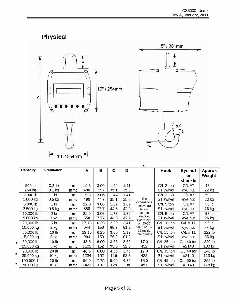
Physical
Capacity Graduation A
B C D Hook Eye nut or
shackle
ApproxWeight
500 lb 250 kg
0.2 lb 0.1 kg
in: mm:
19.3 490
3.06 77.7
1.44 35.1
1.41 35.8
C/L 3 ton S1 swivel
C/L #7 eye nut
48 lb 22 kg
2,000 lb 1,000 kg
1 lb 0.5 kg
in: mm:
19.3 490
3.06 77.7
1.44 35.1
1.41 35.8
C/L 3 ton S1 swivel
C/L #7 eye nut
50 lb 23 kg
5,000 lb 2,500 kg
1 lb 0.5 kg
in: mm:
22.0 558
3.06 77.7
1.82 44.5
1.69 42.9
C/L 5 ton S1 swivel
C/L #7 eye nut
58 lb 26 kg
10,000 lb 5,000 kg
2 lb 1 kg
in: mm:
22.0 558
3.06 7.77
1.75 44.5
1.69 42.9
C/L 5 ton S1 swivel
C/L #7 eye nut
58 lb 26 kg
20,000 lb 10,000 kg
5 lb 2 kg
in: mm:
37.15 944
6.25 159
2.60 65.8
2.41 61.2
C/L 10 ton S1 swivel
C/L # 11 eye nut
97 lb 44 kg
30,000 lb 15,000 kg
10 lb 5 kg
in: mm:
39.15 994
6.25 159
3.00 76.2
3.19 81.3
The dimensions below are
top to bottom
shackle, eye to eye on 25-50
ton / 12.5 –25 metric
ton models C/L 15 ton S1 swivel
C/L # 11 eye nut
122 lb 55 kg
50,000 lb 25,000 kg
10 lb 5 kg
in: mm:
43.5 1105
6.00 152
3.66 93.0
3.62 92.0
17.0 432
C/L 25 ton S1 swivel
C/L 40 ton #2140
220 lb 100 kg
70,000 lb 35,000 kg
20 lb 10 kg
in: mm:
48.6 1234
6.00 152
4.56 116
3.75 92.3
17.0 432
C/L 35 ton S1 swivel
C/L 40 ton #2140
248 lb 113 kg
100,000 lb 50,00 kg
20 lb 10 kg
in: mm:
56.0 1422
7.75 197
5.06 129
4.25 108
18.0 457
C/L 45 ton S1 swivel
C/L 50 ton #2140
392 lb 178 kg
* * *
*

CS3000, Users Rev A, January, 2011
Page 6 of 35
Weights and Measures The CS3000 meets or exceeds class III standards for 3000 division accuracy from 500 lb to 70000 lb. The certification was completed by the National Type Evaluation Program (NTEP)s in accordance with the National Institute of Standards and Technology (NIST) Handbook 44. A NTEP Certificate of Conformance Number 97-135A4 was issued under the National Conference of Weights and Measures.
Parts and Optional Equipment Oversized top lifting eye (100744) This part is applicable to 500 lb - 10,000 lb capacity models. Oversized top shackle (100745) This part is applicable to 20,000 lb and 30,000 lb capacity models. Oversized top shackle (100746) This part is applicable to 50,000 lb and 70,000 lb capacity models. Oversized top shackle (100747) This part is applicable to 100,000 lb capacity models. Anti heat shield (100671) Protection against high heat. Includes oversized hook and custom swivel. Contact Intercomp to a fill out a questionnaire. RS232 Serial data output (100861) The CS3000 has an optional RS232 connection so the unit may communicate with a computer, printer, or remote display. Direct Power on crane unit, 120V / 220V power cable (101055) 120V or 220V power instead of batteries. This option installs the circular connector to the CS3000 which contains the power and serial output pins. Option also includes the 10 ft. retracting coiled power cable. Wall mount 120/220V power supply includes international adapters for U.S, Europe, UK, and Asia.

CS3000, Users Rev A, January, 2011
Page 7 of 35
Operations
Display
Controls
ON / OFF Press and hold this key to apply power to the weighing system electronics. Make sure to hold this key until the display responds (up to 1 second). When power is first applied, the weighing system rapidly performs self-tests of the pad and the internal electronics. When the tests have completed successfully, the system begins weighing. If a problem is detected, the screen displays an error message. If the CS3000 is powered up, press this button to turn the scale off. Note: When the scale is turned off with this key, the scale will be fully off and not able to be turned on with the RFX wireless indicator. If you want the scale to be able to be turned on from the wireless indicator, make sure you turn off the scale with the wireless indicator. ACCUM / TOTAL The scale will not accumulate when the weight is negative, zero, or if the weight is in motion (when Motion Detect is enabled). A display message “Ac.Err” with error icon will be displayed if any of those conditions are present. After a successful accumulation the scale must return to zero before you accumulate the next weight. If you attempt to accumulate the next weight before allowing the scale to return to zero, a display message “Ac.Err” with error icon will be displayed.
MODE The Mode button cycles through the scale’s set-up menu (Mode Menu) when in normal run mode. When in calibration mode, this button cycles through the calibration menu. See the ‘Mode Menu’ and ‘Calibration Menu’ sections for more details.
CS3000, Users Rev A, January, 2011
Page 8 of 35
ZERO Tells the scale to display a zero weight. This button is used any time the scale shows a non-zero value with no weight on the hook. If you press ZERO with weight on the hook, that weight becomes the zero condition for the scale. This can be useful to cancel the weight of any weighing fixtures, such as containers, chains or cables. When this weight is removed, a negative weight shows until the system is zeroed again. If ‘Motion Detect’ (see Calibration Menu) is enabled, the “zero” command will be rejected any time a change in weight is detected. You must wait until the weight is stable before the zero command is allowed. NOTE: The scale contains a feature called Auto Zero Tracking (AZT), which
corrects for slight zero changes during normal operation. If small weights are added slowly, the scale will zero them off.
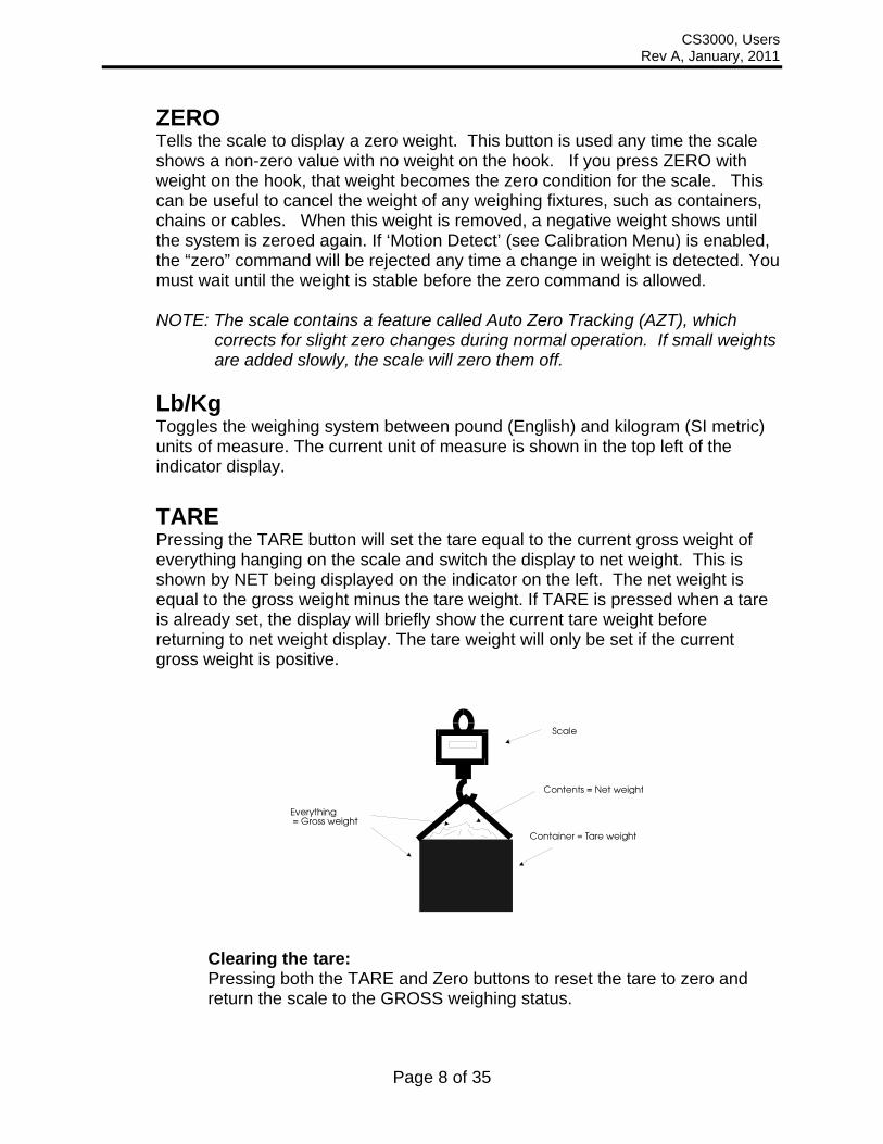
Lb/Kg Toggles the weighing system between pound (English) and kilogram (SI metric) units of measure. The current unit of measure is shown in the top left of the indicator display. TARE Pressing the TARE button will set the tare equal to the current gross weight of everything hanging on the scale and switch the display to net weight. This is shown by NET being displayed on the indicator on the left. The net weight is equal to the gross weight minus the tare weight. If TARE is pressed when a tare is already set, the display will briefly show the current tare weight before returning to net weight display. The tare weight will only be set if the current gross weight is positive.
Clearing the tare: Pressing both the TARE and Zero buttons to reset the tare to zero and return the scale to the GROSS weighing status.

CS3000, Users Rev A, January, 2011
Page 9 of 35
Mode Menu Press the mode button to access the Mode menu. The display will show “Print". If it shows “StEP”, then the calibration button needs to be pressed to return to normal RUN mode, which will allow entry into the Mode Menu when mode is pressed again. (Or enter ‘5’ for the “StEP” entry which will bring you to this Mode Menu.)
At times it will be necessary to enter up to a five digit number. When this is necessary the current number will be displayed with the right most digit flashing. The flashing digit may be incremented by pressing the Lb/Kg button or decremented by pressing the ZERO button. To move one digit to the left, press the TARE button. When you have finished entering a number, press the Mode button. The settings are saved every time Mode is pressed to advance the menu, and the scale can then be turned off.
Step Function Note Default
Print Print Yes or no no
b.LitE Back light On, off, or Auto Auto
SEtP1 Set Point 1 0 to 19999 199999
SEtP2 Set Point 2 0 to 19999 199999
vEr. Firmware Version View only XXXXX
A. rt Average rate 1 to 120 004
A.tHrS Average Threshold 1 to 10000 00000
A off Auto off 000 = off, 1 to 240 060
Prt t Print Mode 0 = On-demand, 1 = Continuous 0
Pbaud Printer baud rate 1200, 2400, 4800, 9600, 19200, 38400, 57600, or 115200
9600
SC id Scale ID 1-190 001
SCLS Number of scales 1-32 01
Proto Protocol StAnd, Lo Pr, C.L00P, or none Lo Pr
i.baud RS485 Interface baud rate
9600 or 115200 9600
radio Radio Enable Yes or no yES
Rf CH Radio Channel 01 to 12 01
Rf.pan Radio Network ID 0 to 65534 8000
Rf.eCp Radio encryption enable Yes or no no
Radio Encryption Key 0 to 65534 00000
Rf.def Restore Radio Defaults 0 or 3 0
Setting the Mode Menu Parameters

CS3000, Users Rev A, January, 2011
Page 10 of 35
1. Press the mode button to access the Mode menu. The display will show “Print". This will allow the user to activate the print function by selecting “yes” or bypass printing by selecting “no”. Press either the zero button or the lb/kg button to toggle the display. When the desired setting is displayed press the mode button to continue through the mode menu.
2. The display will show “b.LitE”. Press the Mode button. The flashing display
shows the current setting. Press either the zero button or the lb/kg button to toggle through Auto, on, and off. With ‘Auto’ selected (default), the backlight will automatically light up when low level light conditions are detected. When the desired setting is displayed press the mode button to continue through the mode menu.
3. The display will show “SEtP1”. Press the Mode button. The display shows the
current setting. When the weight displayed is equal to or greater than the set point, the corresponding icon is displayed on the LCD. During normal weighing mode, the S1 icon on the display will light when the weight is greater than or equal to set point 1. The flashing digit may be incremented by pressing the Lb/Kg button or decremented by pressing the ZERO button. To move one digit to the left, press the TARE button. When the display shows the desired number, press the mode button to continue through the mode menu.
4. The display will show “SEtP2”. Press the Mode button. The display shows the
current setting. During normal weighing mode, the S2 icon on the display will light when the weight is greater than or equal to set point 2. The flashing digit may be incremented by pressing the Lb/Kg button or decremented by pressing the ZERO button. To move one digit to the left, press the TARE button. When the display shows the desired number, press the mode button to continue through the mode menu.
5. The display will show “vEr”. Press the Mode button and the display will show the
current version of firmware loaded in the scale. (view only function) Press the Mode button.
6. The display will show “A. rt”. Press the Mode button. The display shows the
current setting. This number is how many readings will be averaged together before the reading is sent to the display. Higher values will result in a more stable reading, but will take longer to settle to the final value. Note that the scale updates at 4Hz, so an Average Rate of ‘8’ equates to 2 seconds of averaging. Enter a ‘1’ to effectively disable averaging. The flashing digit may be incremented by pressing the Lb/Kg button or decremented by pressing the ZERO button. To move one digit to the left, press the TARE button. When the display shows the desired number, press the mode button to continue through the mode menu.
7. The display will show “A.tHrS”. Press the Mode button. The display shows the
current Average Threshold setting. This setting enables dynamic averaging,

CS3000, Users Rev A, January, 2011
Page 11 of 35
which can improve the settling time of a large Average Rate. If the scale senses a large weight change, it will temporarily suspend averaging, jump to the new weight, and resume averaging. Enter a value of 1-10000 to set the threshold (in display divisions) at which the dynamic averaging triggers. Enter ‘0’ to disable dynamic averaging. When disabled, the averaging will never be suspended. The flashing digit may be incremented by pressing the Lb/Kg button or decremented by pressing the ZERO button. To move one digit to the left, press the TARE button. When the display shows the desired number, press the mode button to continue through the mode menu.
8. The display will show “A. oFF”. Press the Mode button. The display shows the
current setting. The number displayed is the minutes that the scale can remain idle before it automatically powers down into stand-by mode. Note that when the scale powers down into stand-by mode in this way, the scale can still be turned back on with the wireless indicator. Setting this number to “000” will disable the function, meaning the scale will never automatically go into stand-by mode. The flashing digit may be incremented by pressing the Lb/Kg button or decremented by pressing the ZERO button. To move one digit to the left, press the TARE button. When the display shows the desired number, press the mode button to continue through the mode menu.
9. The display will show “Prt t”. Press the Mode button. The display shows the
current setting. The number enables the scales different print modes. (0 for on-demand, 1 for continuous, see ‘serial output’ for more details) The flashing digit may be incremented by pressing the Lb/Kg button or decremented by pressing the ZERO button. When the display shows the desired number, press the mode button to continue through the mode menu.
10. The display will show “PbAUd”. Press the Mode button. The flashing display
shows the current setting of the printer baud rate. The baud rates available are: 1200, 2400, 4800, 9600, 19200, 38400, 57600, and 115200. Press either the zero button or the lb/kg button to toggle the display through the different settings. When the desired setting is displayed press the mode button to continue through the mode menu.
11. Message “SCid” will be displayed. Press the Mode button. A number will be
displayed with 3 dashes following it. This is the scale number. The flashing digit may be incremented by pressing the Lb/Kg button or decremented by pressing the ZERO button. To move one digit to the left, press the TARE button. When the desired number is displayed, press the Mode button.
12. Message “SCLS” will be displayed. Press the Mode button. The display will show
three dashes and then a number. This number is the total number of scales in the system. The flashing digit may be incremented by pressing the Lb/Kg button or decremented by pressing the ZERO button. To move one digit to the left, press the TARE button. When the desired number is displayed, press the Mode button. The maximum number of scales is 32.

CS3000, Users Rev A, January, 2011
Page 12 of 35
13. The display will show “Proto”. Press the Mode button. The flashing display shows the current setting. There are 4 protocol settings for the scale, Standard (“StAnd”), Low Power (“Lo Pr”), Current Loop (“C.L00P”), or “None”. Set this setting to “Lo Pr” for wireless operation with the RFX wireless indicator. Battery life will be improved if “nonE” is chosen, but this disables any wireless operation. Press either the zero button or the lb/kg button to toggle the display through the different settings. When the desired setting is displayed press the mode button to continue through the mode menu.
14. The display will show “i.bAud”. Press the Mode button. The display will show the
current setting flashing. This setting is not used on the CS3000 and can be left at either of the two settings available, 9600 and 115200. Press the mode button to continue through the mode menu.
15. The display will show “rAdio”. Press the Mode button. The display will show the
current setting flashing. This is the radio enable status and is either on or off. Set this setting to “yes” for wireless operation with the RFX wireless indicator. Set this setting to “no” to disable wireless operation which will also increase battery life. If you select “no” the scale will skip the rest of the settings and return to normal weighing. Press either the zero button or the lb/kg button to toggle the display. When the desired setting is displayed press the mode button to continue through the mode menu.
16. The display will show “rF CH”. Press the Mode button. The flashing digit shows
the current setting. All scales and indicators in a system must be set to the same radio channel setting in order to communicate with each other. The flashing digit may be incremented by pressing the Lb/Kg button or decremented by pressing the ZERO button. To move one digit to the left, press the TARE button. When the desired number is displayed, press the Mode button.
17. The display will show “rF.PAn”. Press the Mode button. The display will show the
current setting with the number on the right flashing. All scales and indicators in a system must be set to the same Personal Area Network ID setting in order to communicate with each other. The flashing digit may be incremented by pressing the Lb/Kg button or decremented by pressing the ZERO button. To move one digit to the left, press the TARE button. When the desired number is displayed, press the Mode button.
18. The display will show “rF.ECP”. Press the Mode button. The display will show the
current setting flashing. This is the encryption enable status and is either on or off. Use the Lb/Kg button or the ZERO button to toggle between the settings. When the desired status is flashing, press the Mode button. If “Yes” was selected go to the next step. If “no” was selected skip the next step. The display will show “00000” with the number on the right flashing. The flashing digit may be incremented by pressing the Lb/Kg button or decremented by pressing the ZERO button. To move one digit to the left, press the TARE button. Enter any number from 0 to 65534. This is the encryption key. For security purposes, this setting is

CS3000, Users Rev A, January, 2011
Page 13 of 35
not accessible to view and will always show as “00000”. If you don’t want to change the key enter “00000” to leave it unchanged. All scales and indicators in a system must be set to the same encryption key setting in order to communicate with each other. When the desired number is displayed, press the Mode button
19. The display will show “rF.dEF”. Press the Mode button. The display will show “0”
with the number flashing. The flashing digit may be incremented by pressing the Lb/Kg button or decremented by pressing the ZERO button. Setting the number to 3 will restore the default radio settings. All other numbers will have no affect on the radio set-up. When the desired number is flashing, press the Mode button. The scale will return to normal weighing.
Accum / Total Use To use the accumulating total function, press the “ACCUM TOTAL” button once a load is placed on the scale. The display will briefly show “AC. 1” indicating that the first accumulation has been taken. Each subsequent accumulation will briefly display “AC. X”. (X will be the number of the accumulation that has taken place) The “PRINT” functions will be covered after this section. Accumulation Errors The scale will not accumulate when the weight is negative, zero, or if the weight is in motion. A display message “Ac.Err” with error icon will be displayed if any of those conditions are present. (If in motion the “MOTION” icon will also be displayed.) After a successful accumulation the scale must return to zero before you accumulate the next weight. If you attempt to accumulate the next weight before allowing the scale to return to zero, a display message “Ac.Err” with error icon will be displayed.
Motion Detection System The scale has a motion detection system that can be enabled or disabled from the “Calibration” menu. See “Calibration Menu” section for instructions in setting the motion detection system. When enabled, any motion of the load will disable the zero, tare, print, and accum functions. When accumulating, the message “Ac.Err” with the 'MOTION' icon will be displayed. When attempting to zero, print, of tare the scale the display will show “--- “ with the 'MOTION' icon.

CS3000, Users Rev A, January, 2011
Page 14 of 35
Serial Output (Optional) The serial output is accessed through the mode menu under the “Prt t” option. If “0” is entered it will print on-demand by following the following steps.
1. Press the mode button. The display will show “Print”. 2. Press the mode button once more. Toggle the display to “Yes” by pressing the
lb/kg button. 3. Press the mode button once more and the print command will be sent. After the
print command is sent the scale will return to normal operations. If accumulating all accumulations will be retained.
If “1” is entered it will print in continuous mode. When in continuous mode a print command will be sent approximately one line per second. Print Output Examples On-demand print mode GROSS: 1999.8 lb (No tare or accum total) GROSS: 1999.8 lb (A tare is set) TARE: 999.8 lb NET: 1000.0 lb GROSS: 1999.8 lb (Accumulated total and tare set) TARE: 999.8 lb NET: 1000.0 lb ACC.TOT: 2000.0 lb GROSS: 1999.8 lb (Accum total, but no tare) ACC.TOT: 2000.0 lb Continuous print mode 1999.8 lb 1999.8 lb 1999.8 lb

CS3000, Users Rev A, January, 2011
Page 15 of 35
Scoreboard The CS3000 can be connected to output to a scoreboard (continuous). The signal comes out of the Serial I/O connector located on the side of the unit. The connector has the following pinout:
Signal Pin TXD F GND B
The transmitted signal has the following characteristics: Fixed 8 Data bits, no parity, 1 stop bit. Baud rate is configurable with the ‘printer baud rate’ setting, in the ‘Mode Menu’. The output swings from -9 VDC to 9 VDC. The scoreboard output is an externally available signal designed to drive a numeric overhead display board or a computer's RS-232 input. Continuous print mode transmitted data: xxxxxxx<cr><lf> This represents the NET or GROSS weight, whichever is currently shown on the CS3000 display. This data is repeatedly sent out about once a second, with the exception that the transmission is delayed whenever there is motion. The xxxxxxx field will vary in length depending on the length of the number and could contain a decimal point and/or a minus sign. The scoreboard is designed to work with Intercomp's S400 (4 inch) and SA2000 (2 inch) scoreboards. The following describes how to configure the S400 or SA2000 to work with the scoreboard output.
CS3000, Users Rev A, January, 2011
Page 16 of 35
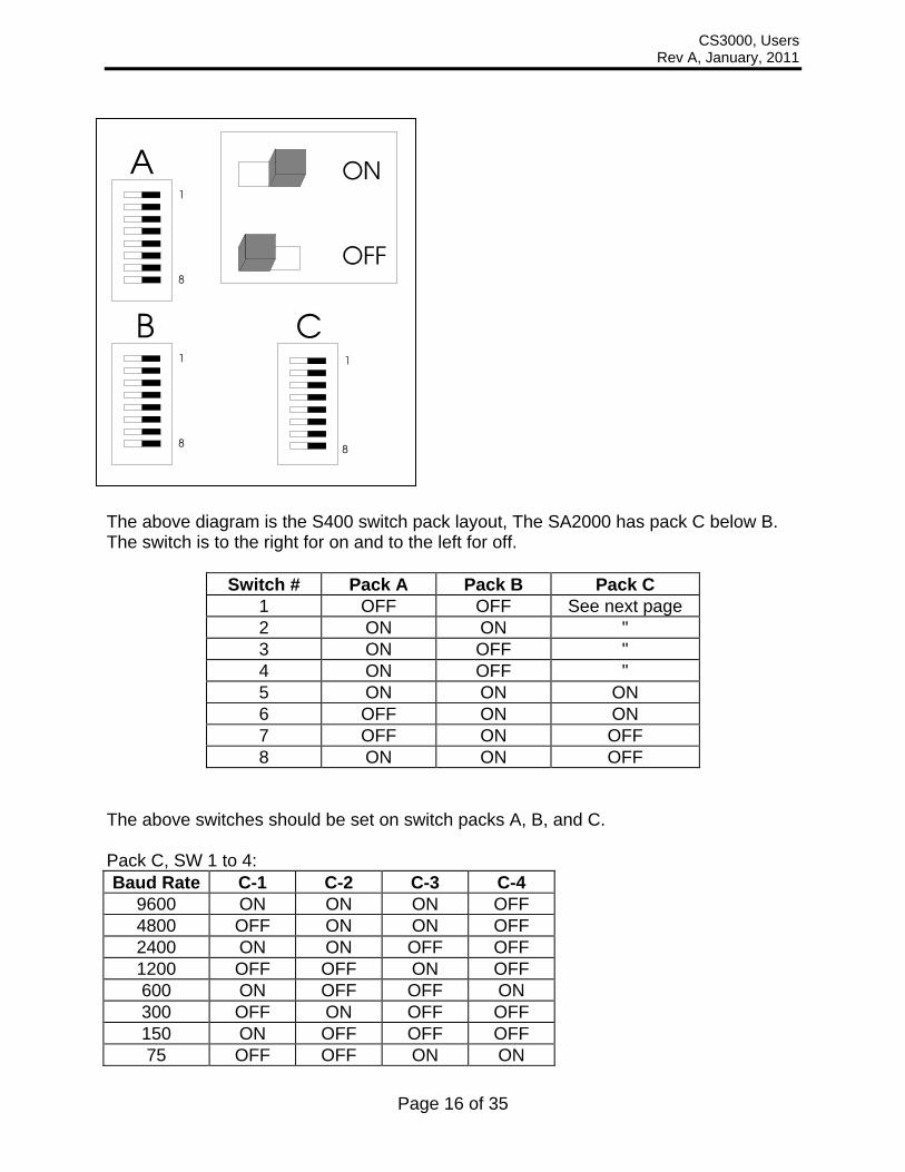
The above diagram is the S400 switch pack layout, The SA2000 has pack C below B. The switch is to the right for on and to the left for off.
Switch # Pack A Pack B Pack C 1 OFF OFF See next page 2 ON ON " 3 ON OFF " 4 ON OFF " 5 ON ON ON 6 OFF ON ON 7 OFF ON OFF 8 ON ON OFF
The above switches should be set on switch packs A, B, and C. Pack C, SW 1 to 4: Baud Rate C-1 C-2 C-3 C-4
9600 ON ON ON OFF 4800 OFF ON ON OFF 2400 ON ON OFF OFF 1200 OFF OFF ON OFF 600 ON OFF OFF ON 300 OFF ON OFF OFF 150 ON OFF OFF OFF 75 OFF OFF ON ON

CS3000, Users Rev A, January, 2011
Page 17 of 35
The connection to an Intercomp S400 display is: CS3000 S400 TXD (F) 2 (RXD) GND (B) 7 (GND)
The connection to an Intercomp SA2000 display is:
CS3000 SA2000 TXD (F) 3 GND (B) 7
The connection to a 9-pin PC communication port is:
CS3000 PC 9-pin TXD (F) 2 GND (B) 5
Note: For some setups it may be necessary to jump pins [6, 1, and 4] together, and pins [7 and 8] together on the PC port connector. The connection to a 25-pin PC communication port is:
CS3000 PC 25-pin TXD (F) 3 GND (B) 7
Note: For some setups it may be necessary to jump pins [6, 8, and 20] together, and pins [4 and 5] together on the PC port connector.

CS3000, Users Rev A, January, 2011
Page 18 of 35
Maintenance
Calibration Menu To initiate calibration press the Mode button. The display will show “StEP”, if it does not, the calibration button needs to be pressed to toggle to allow calibration. The calibration of the scale is protected from accidental change by a switch. The switch is protected by an access plug. The access plug is located on the back of the scale, and is covered by a calibration sticker (seal). The switch is set in the “calibration blocked” mode at the factory.
Enabling the Calibration switch First, remove the calibration sticker which covers the access plug. Using a ¼” Allen wrench, remove the access plug. Insert the Allen wrench in to the hole and press the switch once. The scale is now set to allow calibration.
Step Function Note DefaultStEP skip 000= no skip
002= skip to weight calibration 005= skip to Mode menu
000
U. EnA Unit switch enable Yes or no YES
-dEt- Motion Detect Yes or no no
AdC.rt ADC rate 0 or 1 0
A2t AZT (auto zero tracking) 1 d, 3 d, .5 d, oFF, or.6 d 1 d
2Er0.r Zero range 0= off, 1= 1%, 2= 2%, 3= 5%, 4 = 1%
0
grAd graduation size 0.02, 0.05, 0.1, 0.2, 0.5, 1, 2, 5, 10, 20, 50, or 100
d 1
SAVE Displays for 1 sec and advances
CAP capacity Enter scale capacity 60000
LL-00 No weight applied
HH-01 First weight Enter first weight
LL-01 First weight Load first weight
HH-02 Second weight Enter second weight
LL-02 Second weight Load second weight
HH-03 Third weight Enter third weight
LL-03 Third weight Load third weight
HH-04 Fourth weight Enter fourth weight
LL-04 Fourth weight Load fourth weight
10 points available to enter 3 or more recommended

CS3000, Users Rev A, January, 2011
Page 19 of 35
Note: Number entry: The flashing digit may be incremented by pressing the Lb/Kg button or decremented by pressing the ZERO button. To move one digit to the left, press the TARE button. When you have finished entering a number, press the Mode button. The settings are saved once Mode is pressed to advance the menu, and the scale can then be turned off.
Setting the Calibration Parameters 1. At any point in the following steps, data will be retained by the scale at the step
completed if the power is cycled off. To initiate calibration press the Mode button. The scale shows “StEP”. Press the Mode button. The scale shows “000” with the far right number flashing. To go through all of the calibration parameters, press Mode button with the display showing “000”. To skip to the weight calibration parameters and proceed to step 8 enter “002”. See “Troubleshooting” section for additional codes available. The flashing digit may be incremented by pressing the Lb/Kg button or decremented by pressing the ZERO button. To move one digit to the left, press the TARE button. When the desired number is displayed, press the Mode button
2. The display shows “U. EnA” . Press the mode button. The display will read “YES”.
Pressing Lb/Kg or the ZERO button will toggle the display to “no”, which disables the lb/kg units switching. With the display showing “YES”, press the mode button.
3. The display now shows “-det-”. Press the mode button. The display will read the
current setting. When motion detect is enabled, any motion of the load will disable the zero, tare, print, and accum functions. Pressing the Lb/Kg or the ZERO button will toggle the display. When the desired setting is displayed, press the Mode button
4. The display shows “AdC.rt”. Press the mode button. The display shows the current
setting flashing. This sets the internal A/D conversion time at one of two choices. An entry of ‘0’ results in the full conversion time for the most stable results. An entry of ‘1’ results in a reduced conversion time which extends battery life. It is recommended to leave this set to ‘0’. Note that if this setting is changed, the scale must be recalibrated. The flashing digit may be incremented by pressing the Lb/Kg button or decremented by pressing the ZERO button. When the desired ADC rate is displayed press the Mode button.
5. The display shows “AZt”. Press the mode button. The display shows the current
setting. Press the Lb/Kg or the ZERO button to cycle through the auto zero tracking options (1 d, 3 d, 0.5 d. oFF, or 0.6 d). If the displayed weight is less than the number of grads shown for a given amount of time, the weight will be zeroed off. When the desired auto zero tracking setting is displayed press the Mode button.
6. The display shows “ZEr0.r”. Press the mode button. The display shows the current
setting flashing. The flashing digit may be incremented by pressing the Lb/Kg button or decremented by pressing the ZERO button. The zero range is the percentage the zero can move from the original zero obtained at calibration. The zero button will not work if outside the zero range; and the display will show “ZEr0.r”

CS3000, Users Rev A, January, 2011
Page 20 of 35
with the error icon lit if the zero range is set to 1, 2, or 3. If 4-6 is selected, the zero button will simply not function when an attempt is made to zero the scale outside the range. When the number for desired zero range number is displayed press the Mode button. (0=off, 1=1%, 2=2%, and 3=5%, 4=1%, 5=2%, 6=5%)
7. The display shows “GrAd”. Press the mode button. The display shows the current
setting with the number flashing. Press the Lb/Kg or the ZERO button to cycle through the graduation options. When the desired graduation setting is displayed press the Mode button. (grad options 0.02, 0.05, 0.1, 0.2, 0.5, 1, 2, 5, 10, 20, 50, or 100)
At this point the display will show “SAvE” for about 1 second and advance to show “CAP”.
CS3000, Users Rev A, January, 2011
Page 21 of 35
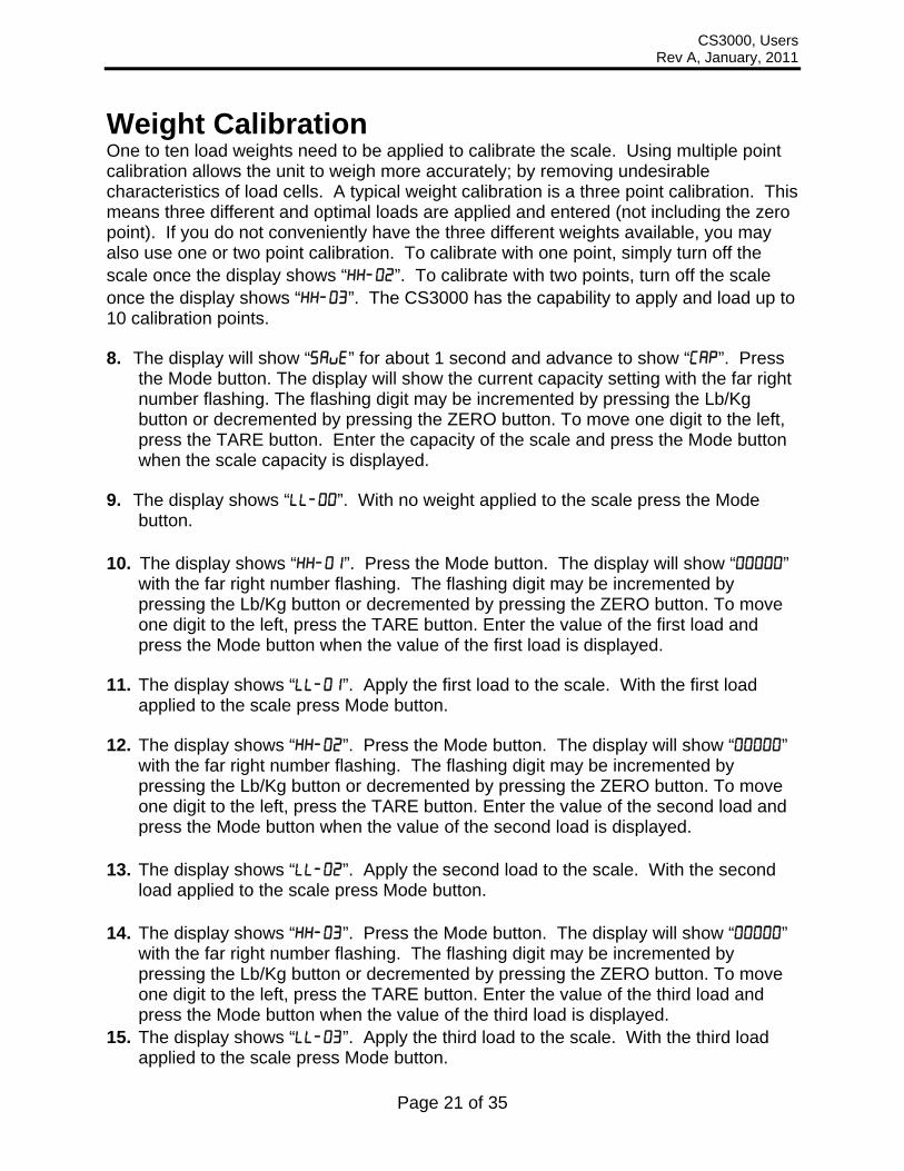
Weight Calibration One to ten load weights need to be applied to calibrate the scale. Using multiple point calibration allows the unit to weigh more accurately; by removing undesirable characteristics of load cells. A typical weight calibration is a three point calibration. This means three different and optimal loads are applied and entered (not including the zero point). If you do not conveniently have the three different weights available, you may also use one or two point calibration. To calibrate with one point, simply turn off the scale once the display shows “HH-02”. To calibrate with two points, turn off the scale once the display shows “HH-03”. The CS3000 has the capability to apply and load up to 10 calibration points.
8. The display will show “SAvE” for about 1 second and advance to show “CAP”. Press
the Mode button. The display will show the current capacity setting with the far right number flashing. The flashing digit may be incremented by pressing the Lb/Kg button or decremented by pressing the ZERO button. To move one digit to the left, press the TARE button. Enter the capacity of the scale and press the Mode button when the scale capacity is displayed.
9. The display shows “LL-00”. With no weight applied to the scale press the Mode
button. 10. The display shows “HH-01”. Press the Mode button. The display will show “00000”
with the far right number flashing. The flashing digit may be incremented by pressing the Lb/Kg button or decremented by pressing the ZERO button. To move one digit to the left, press the TARE button. Enter the value of the first load and press the Mode button when the value of the first load is displayed.
11. The display shows “LL-01”. Apply the first load to the scale. With the first load
applied to the scale press Mode button.
12. The display shows “HH-02”. Press the Mode button. The display will show “00000” with the far right number flashing. The flashing digit may be incremented by pressing the Lb/Kg button or decremented by pressing the ZERO button. To move one digit to the left, press the TARE button. Enter the value of the second load and press the Mode button when the value of the second load is displayed.
13. The display shows “LL-02”. Apply the second load to the scale. With the second
load applied to the scale press Mode button. 14. The display shows “HH-03”. Press the Mode button. The display will show “00000”
with the far right number flashing. The flashing digit may be incremented by pressing the Lb/Kg button or decremented by pressing the ZERO button. To move one digit to the left, press the TARE button. Enter the value of the third load and press the Mode button when the value of the third load is displayed.
15. The display shows “LL-03”. Apply the third load to the scale. With the third load applied to the scale press Mode button.

CS3000, Users Rev A, January, 2011
Page 22 of 35
16. The display shows “HH-04”. Press the Mode button. The display will show “00000” with the far right number flashing. The flashing digit may be incremented by pressing the Lb/Kg button or decremented by pressing the ZERO button. To move one digit to the left, press the TARE button. Enter the value of the forth load and press the Mode button when the value of the forth load is displayed.
17. The display shows “LL-04”. Apply the forth load to the scale. With the forth load
applied to the scale press Mode button. Repeat step 10 and 11 for each additional “HH-05” – “HH10” and “LL-05”- “HH10” combination. If the scale is turned off at any time, the calibration data acquired to that point will be retained. After the Mode button is pressed after “LL-10”, the display will return to normal weighing.
Finished Following calibration, insert the allen wrench and press the cal enable switch to disable calibration. Using a ¼” Allen wrench, replace the access plug and apply a calibration sticker to cover the access plug.
Calibration (Verify)
NOTE: The stated accuracy specifications are based on the graduation setting in the table below. If the graduation setting is set other than the value in the table below the accuracy specification remains with the graduation size listed below.
If your capacity is: Set your graduation to: 500 lb / 250 kg 0.2 lb / 0.1 kg (8)
2000 lb / 1000 kg 1 lb / 0.5 kg (6) 5000 lb / 2500 kg 1 lb / 0.5 kg (6) 10000 lb / 5000 kg 2 lb / 1 kg (5)
20000 lb / 10000 kg 5 lb / 2 kg (4) 30000 lb / 10000 kg 10 lb / 5 kg (3) 50000 lb / 25000 kg 10 lb / 5 kg (3) 70000 lb / 35000 kg 20 lb / 10 kg (2)
100,000 lb / 45000 kg 20 lb / 10 kg (2) To verify that the scale has maintained its calibration points, load the scale at 10% increments and ensure that the display indicates an accuracy of 1% of the load or one display division as indicated in the table above. After all 10 points have been verified the scale is complete.

CS3000, Users Rev A, January, 2011
Page 23 of 35
Periodic Inspection The crane scale and all associated adaptive devices require periodic inspection and maintenance. The frequency and recording of the inspection requirements are found in service categories below and are dependant on the type of service that the equipment is used in as described below. Service Categories Normal Service – Crane scale is operated at less than 85% of its capacity except for isolated instances. Complete the frequent service inspection monthly and record the periodic service inspection annually. Heavy Service – Crane scale is operated at 85% - 100% of its capacity as part of normal usage. Complete the frequent service inspection weekly to monthly and record the periodic service inspection semi-annually. Severe Service – Crane scale is operated at 85% - 100% of its capacity and used in environmental conditions that are unfavorable, harmful or detrimental to the use of the crane scale. Complete the frequent service inspection daily to weekly and record the periodic service inspection quarterly. Inspection Requirements Frequent Service Inspection (records not required) A frequent visual inspection is completed at intervals indicated by the service category above by the operator or designated person of the following.
1. Inspect for structural deformation, cracks or excessive wear of any part of the crane scale or associated adaptive devices.
2. Inspect for loose or missing guards, fasteners, covers, stops, or nameplates. 3. Inspect all functional operating mechanisms and automatic hold and release
mechanisms for improper adjustments interfering with operation of the crane scale or associated adaptive devices.
4. Inspect for distortion such as bending, twisting, or increased throat opening (if applicable)
Periodic Service Inspection (records required) A periodic visual inspection is completed at intervals indicated by the service category above by the operator or designated person and documented to provide the basis for continuing evaluation. The periodic inspection will cover areas in the frequent service inspection above and the following.
1. Inspect for loose bolts or fasteners. 2. Inspect for cracked or worn gears, pulleys, sheaves, sprockets, bearings, chains,
and belts. 3. Inspect for excessive wear of linkages and other mechanical parts. 4. Inspect for excessive wear at hoist hooking points and load support clevices or
pins. 5. Inspect for any visible bends or twists of all used rigging devices. 6. Inspect all latches and locks for proper operation (if applicable)

CS3000, Users Rev A, January, 2011
Page 24 of 35
Removal from Service Criteria Note: Replacement parts of any device or parts of any device used in any aspect of rigging to lift a load shall be at least equal to the original manufacture’s specifications Hooks Hooks shall be removed from service if damage such as the following is found and shall only be returned to service if a qualified person approves their continued use and initiates corrective action.
1. Hooks show cracks, nicks, or gouges. 2. Hook has wear exceeding 10% of the original sectional dimension. 3. Hook has any visible bend or twist from the plane of the unbent hook. 4. Hook has an increase in throat opening of 5% not to exceed ¼ of an inch. 5. If self-locking hooks have the inability to lock. 6. A hook latch that is inoperable (if applicable)
Shackles Shackles shall be removed from service if damage such as the following is visible and shall only be returned to service when approved by a qualified person.
1. If the manufacturers name or trademark and / or the rated load identification is missing or illegible.
2. The device shows signs of heat damage including weld spatter or arc strikes. 3. The device shows excessive pitting or corrosion. 4. The device is bent, twisted, distorted, stretched, elongated, cracked, or has
broken load-bearing components. 5. The device has excessive nicks or gouges. 6. The device has a 10% reduction of the original or catalog dimension at any point
around the body or pin. 7. The device has incomplete pin engagement. 8. The device has excessive thread damage. 9. The device shows evidence of unauthorized welding. 10. Any other condition including visible damage that causes doubt to the continued
use of the shackle.

CS3000, Users Rev A, January, 2011
Page 25 of 35
Power/Batteries
Remove the two caps in the back of the unit. Tip the old cells out. Change the cells with standard alkaline “D” batteries, being careful to put the positive end in first (The end with the bump). Replace the battery caps. Note that the CS3000 will run off a single battery tube, but the battery life will be cut in half.
Legal-for-Trade Sealing
For qualified calibration facilities: 1. After calibration push the calibration switch. The calibration switch is located on the
upper right hand corner on the backside of the scale. 2. Verify that the scale returns to normal weighing when trying to access the weight
calibration. 3. Replace the set screw that covers the cal switch. 4. Apply the protection sticker (sticker must conform to Intercomp’s specifications).

CS3000, Users Rev A, January, 2011
Page 26 of 35
Troubleshooting
Problem Table The following table describes some symptoms with possible causes and solutions. Symptom No power up, nothing on display If any power reaches the control panel, the display driver turns on some random segments. Since we are not seeing this we will assume that no power is reaching the scale circuitry. Some possible causes: Defective wiring harness: Inspect for damaged wiring. Defective battery pack: Measure battery voltage, charge or repair as needed. Defective ON switch: Bridge switch to see if unit turns on. Defective circuitry: Replace control panel. The power supply may be delivering power, but it might be eaten up with a defective circuit board or cable. Unplug the load cell cable. If the scale turns on at this point, a load cell lead is shorted. Turn the power off and try each cell lead in turn. If it is the load cell cable, look for a crushed cable. Symptom Power up to random display We know that some power is reaching the display driver circuit, but the control panel is not working correctly. Test for low battery voltage. Inspect for visible damage. If this fails replace the control panel. Symptom Scale shuts off If the scale turns off IMMEDIATELY after you take your finger off the off button, you may have very low batteries. If this is not the cause replace the control panel. Symptom "Locks up" The scale may be programmed incorrectly. This can be corrected by restoring the correct control parameters. If the Average Rate setting is very high, an active load may not update the display quickly which may be interpreted as a lock up Symptom No backlight Cover the light sensor window. If the light does not turn on, replace the control panel. Please note that the light is not visible in bright sunlight. Symptom Slow operation This may be caused by a programmed change in the filter setting. There is a tradeoff between speed and stability of the display reading. This can be tuned by changing the “Average Rate” setting. Symptom Low battery indicator won't turn off It is possible that the battery output is very low. Check battery voltage level and replace if needed. If the battery voltage is correct then you will need to replace the control panel. Symptom Jumpy or drifty weights This can usually be traced to contamination on circuit boards or a bad load cell. This can also be caused by a rapid change in temperature. The scales need at least one-hour acclimation time for each 10 degrees Fahrenheit of temperature change. Another possibility is powerful radio interference. Symptom No response to one or more keys The switch may be defective. The control panel may be defective. The zero button does not function while the scale is in motion, this is not a defect. Also, the scale may be programmed to ignore the zero button if there is more than a certain amount of weight on the platform. Symptom "Bad" weights First, check weighing technique. Is the scale set on the wrong units settings? Is the reference scale correct? Assuming all this, is the scale spanned correctly? If the reading is exactly 3/4 of the expected value, one of the cells leads may not be providing signal. This would probably be in the load cell or control circuit. The interconnecting wiring or cables may be pinched, cut or crushed. Caution: Changing any circuit board or load cell will affect the calibration. The calibration should be checked after any repairs.
CS3000, Users Rev A, January, 2011
Page 27 of 35
Error Messages
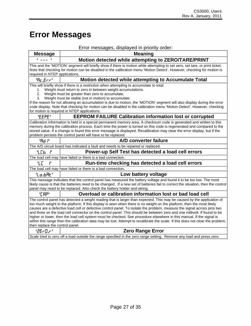
Error messages, displayed in priority order: Message Meaning
' --- ' Motion detected while attempting to ZERO/TARE/PRINT This and the ‘MOTION’ segment will briefly show if there is motion while attempting to set zero, set tare, or print ticket. Note that checking for motion can be disabled in the calibration menu ‘Motion Detect’. However, checking for motion is required in NTEP applications.
'Ac.Err' Motion detected while attempting to Accumulate Total This will briefly show if there is a restriction when attempting to accumulate to total:
1. Weight must return to zero in between weight accumulations. 2. Weight must be greater than zero to accumulate. 3. Weight must be stable (not in motion) to accumulate.
If the reason for not allowing an accumulation is due to motion, the ‘MOTION’ segment will also display during the error code display. Note that checking for motion can be disabled in the calibration menu ‘Motion Detect’. However, checking for motion is required in NTEP applications.
'EEPE' EEPROM FAILURE Calibration information lost or corrupted Calibration information is held in a special permanent memory area. A checksum code is generated and written to this memory during the calibration process. Each time the power is turned on this code is regenerated and compared to the stored value. If a change is found this error message is displayed. Recalibration may clear the error display, but if the problem persists the control panel will have to be replaced.
'AD1' A/D converter failure The A/D circuit board has indicated a fault and needs to be repaired or replaced.
'LCb 1' Power-up Self Test has detected a load cell errors The load cell may have failed or there is a bad connection.
'LC 1' Run-time checking has detected a load cell errors The load cell may have failed or there is a bad connection.
‘Lo.bAt’ Low battery voltage This message indicates that the control panel has measured the battery voltage and found it to be too low. The most likely cause is that the batteries need to be changed. If a new set of batteries fail to correct the situation, then the control panel may need to be replaced. Also check the battery holder and wiring.
'CAP' Overload or calibration information lost or bad load cell The control panel has detected a weight reading that is larger than expected. This may be caused by the application of too much weight to the platform. If this display is seen when there is no weight on the platform, then the most likely causes are a defective load cell or defective control panel. To isolate the problem, measure the signal across pins two and three on the load cell connector on the control panel. This should be between zero and one millivolt. If found to be higher or lower, then the load cell system must be checked. See procedure elsewhere in this manual. If the signal is within this range then the calibration data may be lost. Attempt to recalibrate the scale. If this does not clear the problem, then replace the control panel.
‘ZErO.R’ Zero Range Error Scale tried to zero off a load outside the range specified in the zero range setting. Remove any load and press zero.
CS3000, Users Rev A, January, 2011
Page 28 of 35
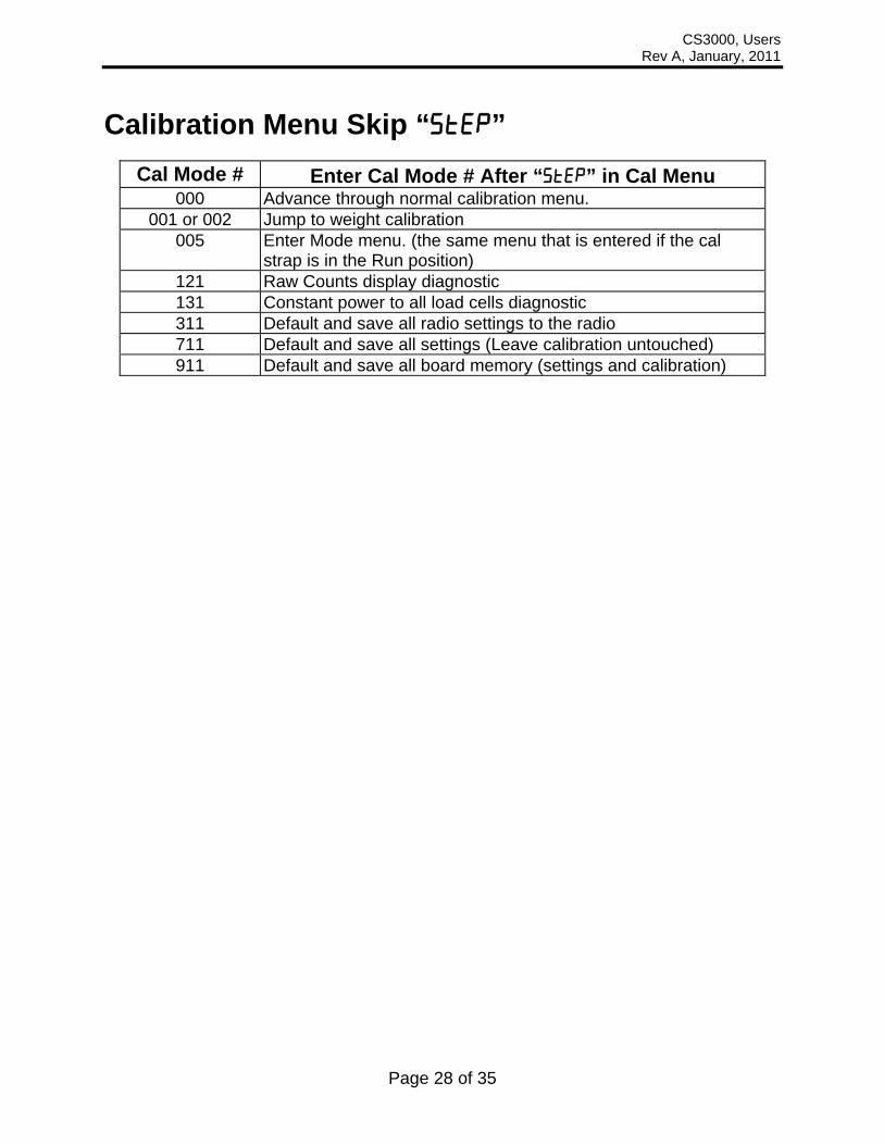
Calibration Menu Skip “step”
Cal Mode # Enter Cal Mode # After “StEP” in Cal Menu 000 Advance through normal calibration menu.
001 or 002 Jump to weight calibration 005 Enter Mode menu. (the same menu that is entered if the cal
strap is in the Run position) 121 Raw Counts display diagnostic 131 Constant power to all load cells diagnostic 311 Default and save all radio settings to the radio 711 Default and save all settings (Leave calibration untouched) 911 Default and save all board memory (settings and calibration)
CS3000, Users Rev A, January, 2011
Page 29 of 35
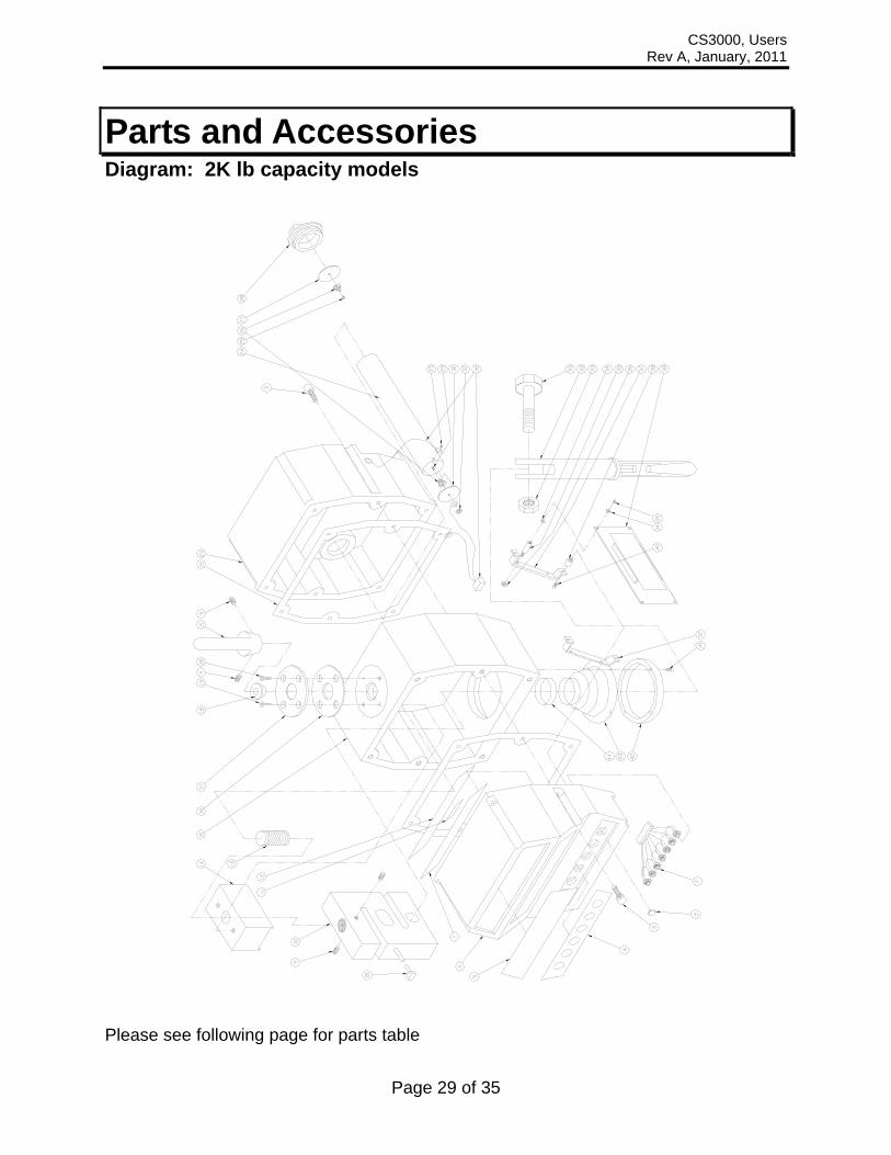
Parts and Accessories Diagram: 2K lb capacity models
Please see following page for parts table

CS3000, Users Rev A, January, 2011
Page 30 of 35
Parts List: 2K lb capacity Item # QTY Part # Description 1 1 000072 control harness 2 6 250058 button cover 3 12 --- .375-16 screw 4 1 250089 keypad overlay 5 1 250090 logo overlay 6 1 500804 CS3000 display end 7 1 250095 window overlay 8 1 220063 4-pin MTA 9 4 --- .25-20 set screw 10 1 000062 loadcell (2K capacity CS3000) 11 1 insert 12 1 500817 display window 13 1 500838 loadcell threaded adapter 14 1 500739 loadcell retainer 15 1 500824 loadcell housing 16 1 500710 retaining ring gasket 17 1 500709 top retaining ring 18 1 500713 retaining ring spacer 19 2 --- .25-20 screw 20 2 --- .25-20 screw 21 1 601039 eye nut 22 2 500805 housing gasket 23 1 550153 end plate 24 2 500707 battery tube 25 20 --- 6-32 screw 26 4 330042 battery spring 27 2 500706 battery plate 28 2 500705 battery cap 29 2 --- 8-32 screw 30 2 500708 battery tube end 31 2 601047 wing nut 32 1 000075 battery harness assembly 34 1 603035 swivel hook assembly 36 16 601014 .031 nylon washer 37 4 601032 6-32 m/f standoff 38 4 601002 6-32 nut 39 2 500808 board mount 40 4 601028 vibration mount 41 1 000980 CS3000 circuit board assembly 42 4 601015 .062 nylon washer 43 4 --- 8-32 screw 44 4 601018 6-32 standoff 47 4 --- 8-32 unc screw 48 1 500803 lower retaining ring 49 2 500818 bellows 50 1 820027 hose clamp

CS3000, Users Rev A, January, 2011
Page 31 of 35
Diagram: 5K lb, 10K lb capacities

CS3000, Users Rev A, January, 2011
Page 32 of 35
See the following page for parts list
Parts List: 5K lb, 10K lb capacity Item # QTY Part # Description 1 1 000072 control harness 2 6 250058 button cover 3 12 --- .375-16 screw 4 1 250492 keypad overlay 5 1 250090 logo overlay 6 1 502575 CS3000 display end 7 1 250005-B window overlay 8 1 220063 4-pin MTA 9 4 -- .25-20 set screw 10 1 000073 loadcell (5K and 10K capacity CS5000) 11 1 insert 12 1 505483 display window 13 1 500740 loadcell threaded adapter 14 1 500984 loadcell housing 15 1 500710 retaining ring gasket 16 1 505482 top retaining ring 17 2 --- .25-20 screw 18 2 --- .25-20 screw 19 1 500754 eye nut 20 2 500805 housing gasket 21 1 550153 End plate 22 2 502627 battery tube 23 20 --- 6-32 screw 24 4 330042 battery spring 25 2 500706 battery plate 26 2 500705 battery cap 27 2 --- 8-32 screw 28 2 500708-B battery tube end 29 2 --- wing nut 30 1 000075 battery harness assembly 31 1 500791 assembly screw 32 1 500791 swivel hook assembly 33 1 500791 assembly nut 34 16 --- .031 nylon washer 35 4 601315 6-32 m/f standoff 36 4 601002 6-32 nut 37 2 500807-B board mount 38 4 601310 vibration mount 39 1 000980 CS3000 circuit board assembly 40 4 --- 8-32 screw 41 4 600015 8-32 unc screw 42 1 500803 lower retaining ring 43 2 500818 bellows 44 1 820027 hose clamp

CS3000, Users Rev A, January, 2011
Page 33 of 35
Diagram: 20K lb, 30K lb capacities
Please see following page for parts list

CS3000, Users Rev A, January, 2011
Page 34 of 35
Parts List: 20K lb, 30K lb capacity Item # QTY Part # Description 1 1 000072 control harness 2 6 250095 button cover 3 12 --- .375-16 screw 4 1 250492 keypad overlay 5 1 250090 logo overlay 6 1 502575 CS3000 display end 7 1 250095 window overlay 8 1 220063 4-pin MTA 9 4 --- .25-20 set screw 10 1 000073
000063 loadcell (20K capacity CS3000) loadcell (30K capacity CS3000)
11 1 insert 12 1 505483 display window 13 1 601051 1-8 locking nut 14 1 500813 top loadcell adapter 15 2 602008 1-8 bolt 16 1 500824 loadcell housing 17 1 500710 retaining ring gasket 18 1 500709 top retaining ring 19 1 601039 eye nut 20 2 --- .25-20 screw 21 2 --- .25-20 screw 22 2 500805 housing gasket 23 1 550153 end plate 24 1 500946 lower loadcell adapter 25 2 500707 battery tube 26 20 --- 6-32 screw 27 4 330042 battery spring 28 2 500706 battery plate 29 2 500705 battery cap 30 2 --- 8-32 screw 31 2 500708 battery tube end 32 2 601047 wing nut 33 1 000075 battery harness assembly 35 1 603063
603038 swivel hook assembly (20K) swivel hook assembly (30K)
37 16 601014 .031 nylon washer 38 4 601032 6-32 m/f standoff 39 4 601002 6-32 nut 40 2 500808 board mount 41 4 601310 vibration mount 42 1 000980 CS3000 Circuit Card assembly 43 4 601015 .062 nylon washer 44 4 --- 8-32 screw 45 4 601315 6-32 standoff 48 4 600015 8-32 unc screw 49 1 500803 lower retaining ring 50 2 500818 bellows 51 1 820027 hose clamp
CS3000, Users Rev A, January, 2011
Page 35 of 35
How to reach Intercomp Service Things to know: 1. The service is for a CS3000 crane scale. 2. When did you purchase your scale? 3. What is your serial number? 4. Whom did you purchase the scale through? For Intercomp Service call or fax: FAX # (763)-476-2613 (763)-476-2531 1-800-328-3336 or fill out Service Support form at: www.intercompcompany.com
Copyright Intercomp Company © 2011 All rights reserved