cs125136 bim execution plans that are actually … bim execution plans that are actually executable...
TRANSCRIPT
Page 1
CS125136
BIM Execution Plans That Are Actually Executable Nick Dyer Okland Construction
Description
Many of our BIM Execution Plans (BEPs) are full of software requirements, file type requirements, and upload requirements. By the time it’s all on paper, you have a document full of requirements and no actions. In this session, we’ll present strategies and lessons learned in creating a BEP that is actionable and still holds everyone accountable to the guidelines needed to create a successful coordination phase of construction. Go beyond a glorified CAD management plan and clash assignments to create shared success for all project stakeholders.
Speaker
Nick Dyer received his Bachelor’s Degree in Construction Management from Weber State University. He has been using Building Information Modeling (BIM) technology for the last 10 years and has been applying his knowledge in technology to both the design and construction sides of the industry. Currently, Nick works for Okland Construction as an Integrated Construction Manager working to expand and implement technology on the jobsite through the use of models and reality capture. He is also helping to support new talent in the industry as an adjunct professor at Weber State University and working with the local Revit Users Group. Pulling from experience on both sides of the industry, Nick is able to support the BIM process from design to project closeout.
Learning Objectives
• Learn how to create BIM Execution Plans that are scalable to project requirements
• Learn how to create BIM Execution Plans that can be used for both design and construction coordination
• Learn how to incorporate BIM Execution Plan elements into contracts
• Learn how to plan and hold contextual meetings to increase coordination productivity

Page 2
Introductions
I introduce myself and Okland Construction here so you may understand where I am coming from in this course. These are the tools and management practices we have developed over the last several years that have worked. There have been many lessons learned in developing these documents and they work for our market and projects. You may need to modify parts and pieces of these documents in order to fit your own individual companies and markets.
The Speaker Nick Dyer – I have been with Okland Construction for the past 6 years. I have been working mostly on health care and higher education projects, with some others sprinkled in-between. I have worked on projects in Utah, Arizona, Idaho, Colorado, and Hawaii.
Okland Construction Okland Construction Company was founded in 1918 in Salt Lake city, Utah. We have offices in Salt Lake City, Utah, Tempe, AZ and Boise, ID and currently have active projects in 19 states. We are a general contractor and have built or are building just about anything you can think of.
Our BIM Tool Bag We use a variety of different tools, but in this course we will be focusing on the use of Revit, Navisworks Manage, and BIM 360 Glue.

Page 3
Creating BIM Execution Plans that are scalable: What’s on the Menu?
A key factor is making your BIM Execution Plan scalable for your project is determining which parts of your plan you need and which ones you don’t. Every project is different, and every project has different requirements. This course will focus on the parts and pieces of a template execution plan so that you may pick and choose which items you need for your projects.
3D Coordination Phases • Phase I: Pre-Construction/Design Coordination
• Phase II: Construction Coordination
• Phase III: Record Model/Final Deliverable
Right from the beginning you are able to start deciding what your project needs. Maybe you are building a bank, you want a model to reference during construction, but doing a full blown 3D coordination process is overkill. This gives you the ability to have modeling requirements for the design team in phase 1, use the model solely as a reference tool in construction phase, and then turn all the model data over to the owner at the end of the project in phase III.
Conversely, you may have to hard bid a complicated science building. In this scenario you usually don’t have the opportunity to perform any Pre-construction coordination, so the requirements in phase II need to be adjusted enough to account for that.
What is the purpose of a BIM Execution Plan? Common terminology says a BIM Execution Plan (BEP) should define who does what, when they do it, and where they do it. However, commonly BEPs get the stigmatism that it should be who models what, when they model it, and where they model it. You can begin to see when you use the word model, it changes the definition dramatically, and turns the whole process into a modeling exercise.
3D coordination or BIM coordination is not a modeling exercise, it a communication exercise. The model is meant to start conversations, not end them. For this reason, we need to bring all the important players to table and give them a voice in the coordination process. Your BIM Execution Plan should be the guideline by which everybody is able to find the information they need and talk about their needs and issues.
Building your BEP Template Phase I – Pre-Construction/Design Coordination and Phase II – Construction Coordination are nearly identical outlines of the same plan, but the modeling requirements and responsibilities change to fit the current phase. To avoid being repetitive, we will discuss both phases concurrently.
All three phases and every BEP needs a certain amount of administrative documentation. These set the stage for all involved so they know where to find documentation outside of the coordination model. Upfront you can address general project requirements such as:
• Roles
• Coordination Schedule
• Modeling Responsibilities
• Model Ownership & Copyright
• Coordination Meetings

Page 4
Roles Most of these roles are very simple and some seem like common sense. However, when they are dictated as part of the plan, people in those roles take their contributions more seriously. It also prescribes clear lines as to what is expected from each team member. Here are some example roles. Obviously, these roles are flexible and can be altered as needed to meet your current phase and project.
(a) Owner – Owner or Owner’s rep is invited to participate in all coordination meetings
(b) Project Manager – Contracts and costs (c) Superintendent – Schedule, field implementation and execution (d) Project Engineer – Document Control, RFIs, submittals, change order review (e) Field Engineer – QAQC, field implementation and execution (f) General MEP Superintendent – Assist as needed (g) IC Manager/Coordinator – Manage coordination process
(i) Model Management 1. Ensuring models are posted properly to BIM 360 Glue 2. Archiving models
(ii) Clash Management 1. Identifying Clashes using the software automated tools 2. Assigning clash viewpoints
(iii) Hosting Coordination meetings with project stake holders (h) Subcontractor Superintendent/Foreman – Driving the coordination effort of
their system(s) and attend coordination meetings (i) Subcontractor Modeler – Modeling all required models as defined by the
LOD’s (i) Reviewing assigned viewpoints (ii) Resolving all assigned clashes through modeling efforts (iii) Providing all needed documents and drawings needed for implementation
of their system(s) (iv) Attend coordination meetings
(j) Project Design Team (i) Architect – Manage architectural model and attend coordination meetings (ii) Mechanical Engineer – Manage mechanical design models and attend
coordination meetings (iii) Electrical Engineer – Manage the electrical design model and be
available to attend coordination meetings (iv) Structural Engineer – Manage the structural design model and be
available to attend coordination meetings
Coordination Schedule Phase I: Pre-Construction/Design During pre-construction, the coordination schedule should be related to the design schedule. Depending on the project requirements, starting too early means that you may not have much to talk about, but starting to late means you don’t have enough time to address issues before construction coordination begins. Timing has to be considered carefully, but these are touch points that usually work best:

Page 5
• 100% Design Development – This is a good place to start. Generally speaking, everybody knows what equipment is going to be required and what space is available. There is usually not enough modeled information to start any clash batches. However, this means it’s a good place to set some “rules of the road”.
o “Rules of the road” can be done in multiple ways, but an easy way to address this is to just create a detail showing zones for each system and then identifying where that detail happens. Usually this can be decided during a short meeting with somebody driving the model. There will always be exceptions to the rules, but two things will happen by following these rules.
� First, it will resolve hundreds of clashes before they ever happen. � Second is it will bring to light any major issues that you may have
with utility routing. o In between stages, somebody needs to be monitoring that these rules are
being followed. The image below shows an example of one of these details and the floor plan.
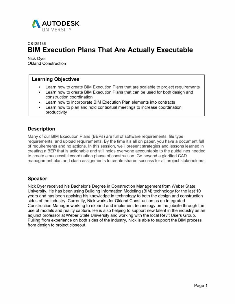
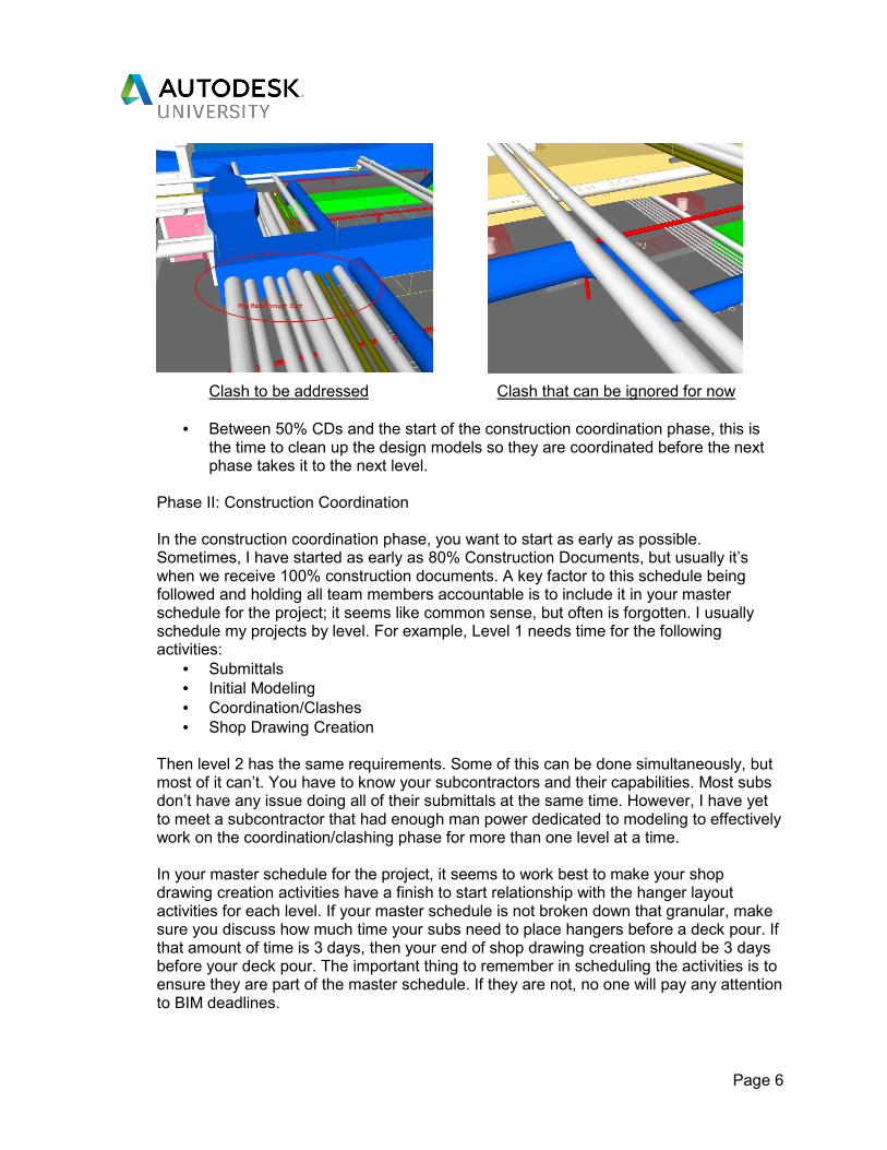
• 50% Construction Documents – This is a good time to start looking at clashes and creating clash assignments for team members to address. It is important to make clash assignments that are relevant to your level of detail/development requirements (See the level of detail/development section for more information). Don’t waste your time and everyone else’s time with tiny clashes in largely open areas. The images below show examples of clashes I would assign, versus those that I would not at this stage.
Page 6
Clash to be addressed Clash that can be ignored for now
• Between 50% CDs and the start of the construction coordination phase, this is the time to clean up the design models so they are coordinated before the next phase takes it to the next level.
Phase II: Construction Coordination In the construction coordination phase, you want to start as early as possible. Sometimes, I have started as early as 80% Construction Documents, but usually it’s when we receive 100% construction documents. A key factor to this schedule being followed and holding all team members accountable is to include it in your master schedule for the project; it seems like common sense, but often is forgotten. I usually schedule my projects by level. For example, Level 1 needs time for the following activities:
• Submittals
• Initial Modeling
• Coordination/Clashes
• Shop Drawing Creation
Then level 2 has the same requirements. Some of this can be done simultaneously, but most of it can’t. You have to know your subcontractors and their capabilities. Most subs don’t have any issue doing all of their submittals at the same time. However, I have yet to meet a subcontractor that had enough man power dedicated to modeling to effectively work on the coordination/clashing phase for more than one level at a time. In your master schedule for the project, it seems to work best to make your shop drawing creation activities have a finish to start relationship with the hanger layout activities for each level. If your master schedule is not broken down that granular, make sure you discuss how much time your subs need to place hangers before a deck pour. If that amount of time is 3 days, then your end of shop drawing creation should be 3 days before your deck pour. The important thing to remember in scheduling the activities is to ensure they are part of the master schedule. If they are not, no one will pay any attention to BIM deadlines.

Page 7
Modeling Responsibilities Phase I:
In the pre-construction phase, the BEP works as the basis for modeling responsibilities and requirements. If this section is included, some boiler plate lines you may want to include would be:
• The sub-consultants will provide models for their respective scopes representing the LOD requirements
• All MEPF models are to be free of conflicts with structure and architectural components
Phase II: In the construction phase you will have to modify some language depending on whether or not coordination was performed in pre-construction. If pre-construction coordination was performed, you can cover it in one line, such as:
• “See BEP from AOR or Owner for additional modeling requirements.”
If no pre-construction coordination was performed, you may use a line like
• The Design team, including Architect, Structural Engineer, Mechanical Engineer, and Electrical Engineer, are to provide respective models representing the current stage of design documents anticipated at LOD 300.
• In addition to these lines you may want to also include other bullet points such as the subcontractors will provide models for their respective scopes representing the LOD requirements
• All MEPF models are to be free of conflicts with structure and architectural components
Model ownership and copyright Most of the time, the model is owned by the project owner, both the authoring model from Revit and the coordination model from Navisworks or BIM 360 Glue. It’s a good idea to make sure everybody is aware that it doesn’t matter if they want to share their models or not, at the end of the day their individual firms don’t own them.
Coordination Meetings Everybody needs to be aware of when and where meetings are to take place. I make a large space on the page similar to this:
Coordination Meeting Times
Each Saturday @ 6:00 am
Model uploads are to occur daily @ 3:59 PM to the BIM 360 Glue
project

Page 8
Obviously, I force myself or anybody else writing the plan to change the ridiculous meeting time. If there is a gotomeeting link, this would be a good place note that information. If meetings are in person, put the location here. I usually note that meetings will take place on gotomeeting and/or at the jobsite, then send the gotomeeting information in an e-mail invite. Holding the meeting at the jobsite allows your subcontractor foreman/superintendents to easily attend and modelers are usually at their home offices.
Modeling Requirements: The modeling exercise of the plan
Origins and orientation You will want to dictate the origin point of your models. If this is for pre-construction, it’s pretty easy to get everyone on the same page when the models are not very developed and easy to move to a specified origin point. However, if there is no pre-designated origin from the design phase, you need to specify it here. To help with this, you can also use an “alignment cube”.
I usually create a drawing showing where to locate the alignment cube and have everyone place it in the same place in their respective models. This cube makes it easy to see if someone is misaligned in both Revit and Navisworks and gives you an easy reference to know by how much.
Building Levels Splitting models up by level seems to work for most projects. However, sometimes you may need to split your model by area or by a combination of both. The important thing is everyone has a reference as to where to split there model up. A simple solution to this is just to include a table such as this one.

Page 9
Project
Acronym
(##)
Level ID
(XX)
Level Name Level Parameters Description/Notes
## L1 Level 1 Below 0’-0” FFE to
17’-0” FFE
## L2 Level 2 15’-0” FFE to 31’-0”
FFE
## L3 Level 3 29’-0” FFE to 45’-0”
FFE
Levels of Development This is the part of the plan when you get to clarify standards for modeling and reliance. Even though most people now have a good idea as to what is meant by the different LOD levels, I include them in the plan so that they may be referenced up front. This also cuts out any gray area in understanding between LOD’s.
LOD 100 - The model element may be graphically represented in the model with a symbol or other generic model representation. LOD 200 – The model element is graphically represented within the model as a generic system, object, or assembly with the approximate quantities, size, shape, location, and orientation. Non-graphic information may also be attached to the model. LOD 300 – The model element is graphically represented with the model as a specific system, object or assembly in terms of quantity, size, shape, location, and orientation. Non-graphic information may also be attached to the model. LOD 400 - The model element is graphically represented with the model as a specific system, object or assembly in terms of quantity, size, shape, location, and orientation with detailing, fabrication, assembly, and installation information. Non-graphic information may also be attached to the model. LOD 500 – The model element is a field verified representation in terms of size, shape, location, quantity, and orientation. Non-graphic information may also be attached to the model.
An easy way to identify what LOD’s need to be applied is to just be very straight forward about what you expect. As a starting place, you can use the AIA G202 form, or you can create something like the table below. During the preconstruction phase/design phase, you will have lower LOD requirements, but when construction coordination begins, the LOD requirements will be increased for shop drawings.
When starting the Preconstruction phase, I usually will provide the LODs I want to the design team as a wish list of modeling requirements. Then in the kick-off meeting we are able to discuss what will be provided as well as what won’t be. The point of the discussion is to increase transparency between team members so we are all on the same page.

Page 10
Model Name/
Systems Included
Level of Detail (LOD)
Please include as a minimum the following components
Responsibility
Architectural 1) Furniture – LOD 200
2) Millwork – LOD 200
3) Doors – LOD 200
4) Windows – LOD 200
5) Floors – LOD 200
6) Walls – LOD 300
7) Curtain Walls – LOD 300
8) Ceilings – LOD 300
9) Roof Systems – LOD 300
10) Specialty equipment – LOD 300
Architect
Concrete Foundation
Concrete Walls
Concrete SOG
Concrete Decks
1) Concrete Slabs – LOD 300
2) Concrete Footings – LOD 300
3) Concrete Walls – LOD 300
4) Concrete Penetrations – LOD 200
5) Concrete Openings – LOD 200
Structural
Engineer
Masonry Walls
Masonry Shafts
1) CMU Walls – LOD 300
2) CMU Openings – LOD 200
3) CMU Embeds – LOD 300
4) CMU Penetrations – LOD 200
Structural
Engineer
Structural Steel
Misc. Steel
Steel Stairs/Rail
1) Steel Columns – LOD 400
2) Steel Beams – LOD 400
3) All Structural Steel Connections. – LOD 400
4) All Steel Embeds and embedded items. – LOD 400
5) All stairs, catwalks, grating, and their support systems –
LOD 400.
6) All hangars and support systems. – LOD 400
7) All embeds being provided for other trades. – LOD 400
Steel Erector
Sheet Metal
1) All Ductwork with flanges – LOD 400
2) All Ductwork insulation – LOD 200
3) Air Handling Equipment including AHU’s, VAV’s, FCU’s,
RTU’s, etc. – LOD 400
4) Electrical work associated with mechanical equipment. –
LOD 400
5) Smoke Dampers, Fire Dampers, and F/S Dampers – LOD
400
6) T-Stats, pressure sensors, and other in-line devices – LOD
400
7) All hangars and support systems. – LOD 400
Mechanical
Subcontractor

Page 11
Plumbing 1) All Drain Piping – LOD 400
2) All Vent Piping – LOD 400
3) Piping associated with mechanical equipment 1/2” or
larger. – LOD 400
4) All plumbing and gas piping 1” or larger. – LOD 400
5) Pipe insulation – LOD 300
6) All pipe fittings and connections. – LOD 400
7) Pipe Valves – LOD 400
8) Sleeves as necessary to penetrate floor/roof – LOD 200
9) All hangars and support systems. – LOD 400
10) Piping equipment access zones will be modeled as a
transparent object and identified as such. – LOD 200
11) All clearance zones should be labeled as such
12) In Revit the word “Clearance” should be in the material
Mechanical
Subcontractor
Electrical and Lighting 1) All conduit 1" or larger in diameter. – LOD 400
2) All Conduit racks with more than (1) conduit less than 1” in
diameter – LOD 400
3) All Light fixtures – LOD 400
4) Light Accessories & Supports – LOD 400
5) Light/Chandelier Hoists if different than structure – LOD
400
6) In Exposed Areas (Ceilings or Walls) – LOD 400
7) Cable Tray and under floor trays. – LOD 400
8) Electrical Panels & Equipment. – LOD 400
9) All hangars and support systems. – LOD 400
10) All power feeds to equipment. – LOD 400
11) Electrical equipment access zones will be modeled as a
transparent object and identified as such – LOD 200
12) All clearance zones should be labeled as such
13) In Revit the word “Clearance” should be in the material
Electrical
Subcontractor
Low-Voltage:
Phone/Data, A/V,
Special Systems,
Security, Fire Alarm
1) All Components & Equipment – LOD 400
2) All Speakers, Cameras, Control Devices/Boxes – LOD 400
3) Cable Trays – LOD 400
4) All hangers and support Systems – LOD 400
5) Conduit runs where location is known or critical – LOD 400
6) Cable tray and J-hook clearance zones for maintenance and
access – LOD 200
Low Voltage
Subcontractor
Fire Sprinkler 1) All fire protection components – LOD 400
2) All hangars and support systems. – LOD 400
3) Fire protection equipment access zones will be modeled as
a transparent object and identified as such. – LOD 200
Fire
Protection
Page 12
Naming conventions Now that we know what levels, areas, and scopes need to be modeled, you need a naming convention. Naming conventions need to be as short as possible. Something simple like ProjectNumber_Level_Scope will suffice in most cases, but the name can be made to be more complex or specific as needed.
File types Typically, you will have different members of the team using different kinds of software. It’s nice when everyone uses Revit, but it’s not practical. For that reason, it is usually best to require Navisworks Cache files (.nwc). This file type cuts through the different file types and provides something everyone can read within both the Glue and Navisworks environments. Then using features in AutoCAD and Revit 2018, team members can import the geometry back into their authoring software as needed.
Clashing Procedure
You need clash assignments to start conversations, but they need to be straight forward enough to be substantive. The creation of a clash hierarchy helps set this up. This way clashes are only assigned once and you don’t end up with several repeats. For example:
a) Clash Hierarchy – initial Clash assignments will be based on the following:
i) Architecture – including lights
ii) Structural
iii) DWV
iv) Duct
v) Pneumatic tube
vi) Fire mains
vii) Mech. Pipe
viii) Domestics, med gas, process, misc. plumbing
ix) Electrical
x) Data
xi) Fire branches
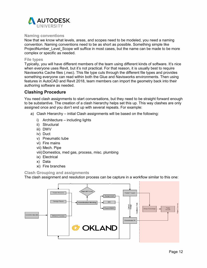
Clash Grouping and assignments The clash assignment and resolution process can be capture in a workflow similar to this one:

Page 13
In order to make clash assignments more manageable, the BIM Manager should group the clashes. This will be different for each project and can be time consuming. However, this has two major benefits:
1. You get to control the clash assignments and who they are assigned too. 2. Your modelers will spend more time resolving clashes rather than fishing through
clashes that don’t matter.
Once clashes are grouped, an easy way to assign them is to export them as saved viewpoints. Viewpoints can then be shared in Navisworks and in BIM 360 Glue, so everyone involved can see them, not just the modelers. Assignments all require some kind of action and most do not need to be discussed in the weekly coordination meeting. The following workflow can help fish through the assignments so only the ones that need discussion from the whole team are discussed in the weekly coordination meetings.
Meetings
Kick-off Meeting The kick-off meeting needs to be structured so you ensure that you hit all the major points of your BEP. A typical Kick-off meeting has the following agenda items:
1) Introductions – The Kick-off meeting needs to be an in person meeting, unless some team members are out of state. This gives everyone a chance to meet their other team mates before they become faceless names on a gotomeeting.
2) Goals for Coordination – This is everyone’s opportunity to express their concerns and goals. As the general contractor, I have different goals than my subcontractors. So, it’s important to get everything out on the table so everyone knows what’s important.
3) Review of Schedule – Review of the overall schedule for coordination and important milestones
4) Review of BIM Execution Plan – you will have written this prior to the meeting and it will take the bulk of the time.
5) Review of “Rules of the Road” – If you did pre-construction, this would just be providing the same routing rules again to the subcontractors. However, if there was not an opportunity to perform pre-construction coordination, there are a couple of things to look for. First, some design teams will provide a mechanical detail for layering the MEP systems in the interstitial space above the ceiling. This detail can work as a guide in creating your routing rules. If there is no detail, first contact your design team and find out if they did anything specific for routing rules. If the answer to all of these things is no, then it will be up to you to determine with your team what the routing rules should be. This will become an action item to create a drawings and the detail for reference, same as shown in the pre-construction phase.
Page 14
6) Overall Model Review – This is the time to do an initial review of the model. It may be helpful to run some preliminary clash batches so you can identify any areas of trouble that need to take priority as everybody gets started.
7) Next Meeting – The team should agree on the day and time of the regularly scheduled meetings. It’s easy to set these up at the end of the kick-off meeting or during the review of the BEP.
Regularly Scheduled Meetings Patrick Lencioni wrote a book entitled “Death by Meeting: A Leadership Fable”. With a title like that you might think he advocates for less meetings, but actually it discusses using meetings as tools and holding more of them. Obviously, the meetings presented in the book have to be modified to fit the coordination team, but there are 3 major meetings that need to take place:
• Daily stand up meeting
• Weekly coordination meeting
• Area sign-off meeting
The daily standup meeting This meeting is a 10-15 minute phone call. At a minimum, you should have the modelers on this call, but I stress that that is the minimum. Since it is a phone call, services like Uber conference are helpful as it will automatically call your attendees instead of them having to remember to call in.
During this meeting, everyone needs to talk about at least 1 priority they have for that day. This also gives them the opportunity to hear other’s priorities and if two or more people need to have a more in-depth discussion, this meeting can get them started. It’s important during this meeting to push your attendees to be as specific as possible so you don’t end up with answers like “today I am working on my clash assignments” 3 days in a row and then only 2 assignments are resolved come weekly coordination meeting time.
The Weekly Coordination Meeting Weekly coordination meetings should have everyone in attendance. Meeting preparation is the key to a good substantive meeting. To prepare for this meeting, you should already have a good idea about the big priorities from your daily standup meetings. Next, you should have already grouped all of the new clash assignments from the previous week, so you can see what major clashes are still not resolved. Lastly, you should be running clash outside of the assignments so you can find areas with lots of conflicts and will take discuss with most of or the entire team. For instance, running a clash batch like “Duct Vs. All other MEP” is a good way to find out if there are any areas that everyone is struggling getting around duct. Also if you see entire corridors struggling, this could mean that you need to have a discussion about re-sizing duct it could mean that team members are not following the routing rules set in the kick-off meeting.
Your weekly coordination meeting needs to have some structure, but don’t let your agenda dictate the meeting. There are a few things every meeting needs:
1) Attendance – since you are making important decisions during this meeting, you will want to note who was part of the conversation was when those decisions where discussed.
2) Review of the schedule 3) Review of any open items.

Page 15
All new items come from either your review of the model or from what your team wants to talk about. This way, you become more of discussion leader rather than a dictator. This also allows for more transparency as team members are able to bring their concerns to the table rather than just hoping that you will.
Each week you need some way to measure progress, not only through clash assignments, but also for model completeness. An easy way to do this is just to create a couple of spread sheets. Your company may be interested in different elements, but here is an example
Sign-Off Meeting You will reach a point with each level or area that you will need to sign it off. Sign-off can be driven by either clash results (meaning all the clashes are resolved) or by the construction schedule (Meaning you’re out of time). This meeting is really just your time to make sure everyone is aware that you are moving to a new area of the building and a quick review of any open items still remaining, which should just be unresolved clashes but could be other items as well.
Final Deliverables
The final deliverable is going to change based on project requirements. That said, the owner usually owns all of the model information. So as standard practice, you will want to include what happens to the model at the end of the project. This can be really simple if nothing is required from the owner for O&M Linking or something similar. Here is an example of a really easy turnover.
1. Final Deliverable
a) Models- Each Trade will be responsible to providing the following files for EACH separate model provided:
i) NavisWorks – NavisWorks Cache (.nwc) ii) 3D AutoCAD (.dwg) or a Revit (.rvt) file

Page 16
b) If a single overall file is available that includes models for all the separate levels or areas, this file shall also be submitted.
c) The digital files are to be posted to BIM 360 Glue.
d) The General Contractor will provide the owner with all filed on an external hard drive.
Summary
To sum things up, we now have the tools we need to match up BIM Execution Plans with project requirements by setting clear LOD expectations. BIM Execution Plans can be used for both design and construction by splitting them up into three phases. We can also incorporate BIM Execution Plan elements into contracts by either including the BEP as part of the contract or even just the LOD requirements. And lastly, we will have more contextual meeting by not making the coordination meeting the catch all for everything and have smaller meetings in between coordination meetings. Now it’s time to start working the plan.
Good Luck!