cs106a handout 24 assignment 5: array algorithms...cs106a handout 24 winter 2013-2014 february 19,...
TRANSCRIPT
CS106A Handout 24Winter 2013-2014 February 19, 2014
Assignment 5: Array Algorithms
Introduction
Arrays are a fundamental and versatile tool for representing, manipulating, and transforming data. In this assignment, you'll see how arrays can be applied to generate and manipulate music and im-ages.
This assignment consists of three smaller programs. Part One of this assignment (Steganogra-phy) explores how arrays can be used to represent images and how simple transformations on im-ages can be used to hide secret messages. Part Two of this assignment (Tone Matrix) lets you use arrays to play sounds and construct an awesome musical instrument. Part Three of this assignment (Histogram Equalization) shows how you can use arrays in a variety of contexts to manipulate photographs and recover meaningful data from overexposed or underexposed pictures.
By the time you've completed this assignment, you will have a much deeper understanding of how to use arrays to model and solve problems. You'll also be able to share secret messages with your friends, compose music, and fix all your old family photos.
Due Friday, February 28 at 3:15PM
Review Session: Sunday, February 23, 7:00PM – 8:00PM in Hewlett 200
2 / 16
Part One: Steganography*
Suppose that you want to send a secret message to someone else without other people being able to read it. One way to do this would be to hide the message inside of something innocuous so that no one would think to look for it. For example, suppose that I send you the following note:
Andrew Luck is quarterback for the Indianapolis Colts. He plays football excellently!
This message looks like a comment on Stanford's (wonderful) former quarterback. However, if you look closer, you can see that some of the letters have been bolded. If you just read those letters, you get nubian ibex, which was the secret message I was trying to send to you. The secret message isn't en-crypted – anyone who knows where to look for the message can still read it – but has been hidden so that people might not even notice it exists. The art and science of concealing hidden messages is called steganography. In this part of the assignment, you'll implement a system of image steganography to conceal messages in pictures.
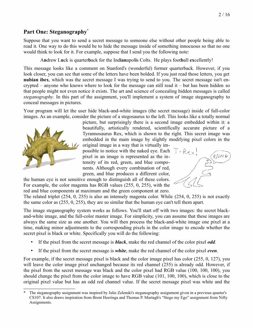
Your program will let the user hide black-and-white images (the secret message) inside of full-color images. As an example, consider the picture of a stegosaurus to the left. This looks like a totally normal
picture, but surprisingly there is a second image embedded within it: a beautifully, artistically rendered, scientifically accurate picture of a Tyrannosaurus Rex, which is shown to the right. This secret image was embedded in the main image by slightly modifying pixel colors in the original image in a way that is virtually im-possible to notice with the naked eye. Each pixel in an image is represented as the in-tensity of its red, green, and blue compo-nents. Although every combination of red, green, and blue produces a different color,
the human eye is not sensitive enough to distinguish all of these colors. For example, the color magenta has RGB values (255, 0, 255), with the red and blue components at maximum and the green component at zero. The related triplet (254, 0, 255) is also an intensely magenta color. While (254, 0, 255) is not exactly the same color as (255, 0, 255), they are so similar that the human eye can't tell them apart.
The image steganography system works as follows. You'll start off with two images: the secret black-and-white image, and the full-color master image. For simplicity, you can assume that these images are always the same size as one another. You will then process the black-and-white image one pixel at a time, making minor adjustments to the corresponding pixels in the color image to encode whether the secret pixel is black or white. Specifically you will do the following:
• If the pixel from the secret message is black, make the red channel of the color pixel odd.
• If the pixel from the secret message is white, make the red channel of the color pixel even.
For example, if the secret message pixel is black and the color image pixel has color (255, 0, 127), you will leave the color image pixel unchanged because its red channel (255) is already odd. However, if the pixel from the secret message was black and the color pixel had RGB value (100, 100, 100), you should change the pixel from the color image to have RGB value (101, 100, 100), which is close to the original pixel value but has an odd red channel value. If the secret message pixel was white and the
* The steganography assignment was inspired by Julie Zelenski's steganography assignment given in a previous quarter's CS107. It also draws inspiration from Brent Heeringa and Thomas P. Murtagh's “Stego my Ego” assignment from Nifty Assignments.
3 / 16
color pixel has RGB value (0, 0, 0), you would leave the original pixel untouched because its red chan-nel (0) is already even. However, if the secret pixel was white and color pixel has value (255, 255, 255), you would change the color pixel to (254, 255, 255), which is close to the original color but with an even number in its red channel. These changes are so subtle that they're completely imperceptible and the resulting image will look perfectly normal, but the changes are prominent enough for the com-puter to use them to reconstruct the hidden message later on.
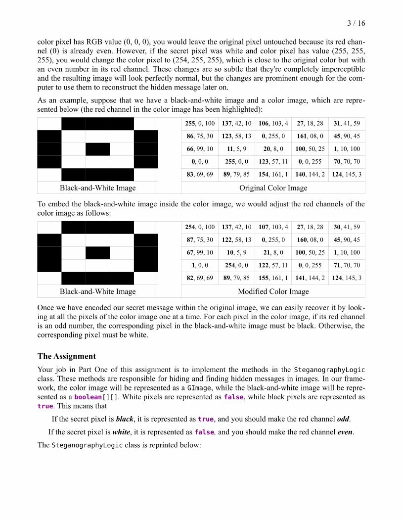
As an example, suppose that we have a black-and-white image and a color image, which are repre-sented below (the red channel in the color image has been highlighted):
255, 0, 100 137, 42, 10 106, 103, 4 27, 18, 28 31, 41, 59
86, 75, 30 123, 58, 13 0, 255, 0 161, 08, 0 45, 90, 45
66, 99, 10 11, 5, 9 20, 8, 0 100, 50, 25 1, 10, 100
0, 0, 0 255, 0, 0 123, 57, 11 0, 0, 255 70, 70, 70
83, 69, 69 89, 79, 85 154, 161, 1 140, 144, 2 124, 145, 3
Black-and-White Image Original Color Image
To embed the black-and-white image inside the color image, we would adjust the red channels of the color image as follows:
254, 0, 100 137, 42, 10 107, 103, 4 27, 18, 28 30, 41, 59
87, 75, 30 122, 58, 13 0, 255, 0 160, 08, 0 45, 90, 45
67, 99, 10 10, 5, 9 21, 8, 0 100, 50, 25 1, 10, 100
1, 0, 0 254, 0, 0 122, 57, 11 0, 0, 255 71, 70, 70
82, 69, 69 89, 79, 85 155, 161, 1 141, 144, 2 124, 145, 3
Black-and-White Image Modified Color Image
Once we have encoded our secret message within the original image, we can easily recover it by look-ing at all the pixels of the color image one at a time. For each pixel in the color image, if its red channel is an odd number, the corresponding pixel in the black-and-white image must be black. Otherwise, the corresponding pixel must be white.
The Assignment
Your job in Part One of this assignment is to implement the methods in the SteganographyLogic class. These methods are responsible for hiding and finding hidden messages in images. In our frame-work, the color image will be represented as a GImage, while the black-and-white image will be repre-sented as a boolean[][]. White pixels are represented as false, while black pixels are represented as true. This means that
If the secret pixel is black, it is represented as true, and you should make the red channel odd.
If the secret pixel is white, it is represented as false, and you should make the red channel even.
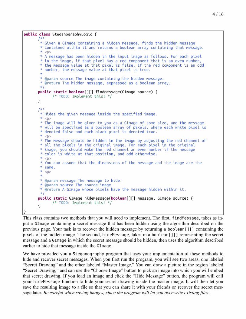
The SteganographyLogic class is reprinted below:
4 / 16
public class SteganographyLogic {/** * Given a GImage containing a hidden message, finds the hidden message * contained within it and returns a boolean array containing that message. * <p> * A message has been hidden in the input image as follows. For each pixel * in the image, if that pixel has a red component that is an even number, * the message value at that pixel is false. If the red component is an odd * number, the message value at that pixel is true. * * @param source The image containing the hidden message. * @return The hidden message, expressed as a boolean array. */public static boolean[][] findMessage(GImage source) {
/* TODO: Implement this! */}
/** * Hides the given message inside the specified image. * <p> * The image will be given to you as a GImage of some size, and the message * will be specified as a boolean array of pixels, where each white pixel is * denoted false and each black pixel is denoted true. * <p> * The message should be hidden in the image by adjusting the red channel of * all the pixels in the original image. For each pixel in the original * image, you should make the red channel an even number if the message * color is white at that position, and odd otherwise. * <p> * You can assume that the dimensions of the message and the image are the * same. * <p> * * @param message The message to hide. * @param source The source image. * @return A GImage whose pixels have the message hidden within it. */public static GImage hideMessage(boolean[][] message, GImage source) {
/* TODO: Implement this! */}
}
This class contains two methods that you will need to implement. The first, findMessage, takes as in-put a GImage containing a secret message that has been hidden using the algorithm described on the previous page. Your task is to recover the hidden message by returning a boolean[][] containing the pixels of the hidden image. The second, hideMessage, takes in a boolean[][] representing the secret message and a GImage in which the secret message should be hidden, then uses the algorithm described earlier to hide that message inside the GImage.
We have provided you a Steganography program that uses your implementation of these methods to hide and recover secret messages. When you first run the program, you will see two areas, one labeled “Secret Drawing” and the other labeled “Master Image.” You can draw a picture in the region labeled “Secret Drawing,” and can use the “Choose Image” button to pick an image into which you will embed that secret drawing. If you load an image and click the “Hide Message” button, the program will call your hideMessage function to hide your secret drawing inside the master image. It will then let you save the resulting image to a file so that you can share it with your friends or recover the secret mes-sage later. Be careful when saving images, since the program will let you overwrite existing files.

5 / 16
If you load an image that contains an hidden message and click the “Recover Message” button, the pro-gram will call your findMessage function and show the secret message in the panel marked “Secret Drawing.” If the original image didn't contain a secret message, then you're likely to get back garbage patterns, since your findMessage function will still read back the red channels and try to reconstruct the image.
Here is a screenshot of this program in action:
Advice, Tips, and Tricks
For this portion of the assignment, we strongly suggest starting off by implementing the findMessage function and testing it out on the sample images that we've provided for you. That way, you can con-firm that your logic for decoding messages works properly before you test it out in conjunction with your hideMessage function.
When implementing hideMessage, make sure that you don't increase the red channel above 255 or de-crease it below 0. If you do, the red channel will “wrap around,” with values below 0 wrapping back around up to 255 and values above 255 wrapping down to 0. If you do this, you might see bright red or bright cyan patterns in the resulting image due to the red channel flipping between low and high values.
6 / 16
Part Two: Tone Matrix*
In this part of the assignment, you'll build a really nifty piece of software that combines music and vi-suals – the Tone Matrix!
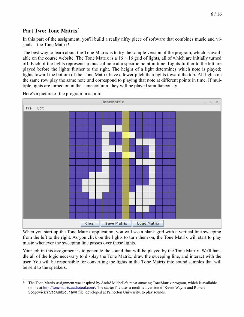
The best way to learn about the Tone Matrix is to try the sample version of the program, which is avail-able on the course website. The Tone Matrix is a 16 × 16 grid of lights, all of which are initially turned off. Each of the lights represents a musical note at a specific point in time. Lights further to the left are played before the lights further to the right. The height of a light determines which note is played: lights toward the bottom of the Tone Matrix have a lower pitch than lights toward the top. All lights on the same row play the same note and correspond to playing that note at different points in time. If mul-tiple lights are turned on in the same column, they will be played simultaneously.
Here's a picture of the program in action:
When you start up the Tone Matrix application, you will see a blank grid with a vertical line sweeping from the left to the right. As you click on the lights to turn them on, the Tone Matrix will start to play music whenever the sweeping line passes over those lights.
Your job in this assignment is to generate the sound that will be played by the Tone Matrix. We'll han-dle all of the logic necessary to display the Tone Matrix, draw the sweeping line, and interact with the user. You will be responsible for converting the lights in the Tone Matrix into sound samples that will be sent to the speakers.
* The Tone Matrix assignment was inspired by André Michelle's most amazing ToneMatrix program, which is available online at http://tonematrix.audiotool.com/. The starter file uses a modified version of Kevin Wayne and Robert Sedgewick's StdAudio.java file, developed at Princeton University, to play sounds.
7 / 16
How the Matrix Works
As the vertical bar sweeps across the Tone Matrix, the Tone Matrix will play sounds corresponding to which lights in the current column are lit up. Each row in the tone matrix has an associated sound clip that represents the sound that should be played when a light in that row is played. The tone matrix then generates music according to the following algorithm:
• Determine which lights are turned on in the current column.
• Each of those lights will be in a different row. For each of those rows, obtain the sound clip cor-responding to that row.
• Play all of those sound clips simultaneously.
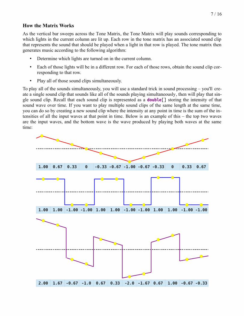
To play all of the sounds simultaneously, you will use a standard trick in sound processing – you'll cre-ate a single sound clip that sounds like all of the sounds playing simultaneously, then will play that sin-gle sound clip. Recall that each sound clip is represented as a double[] storing the intensity of that sound wave over time. If you want to play multiple sound clips of the same length at the same time, you can do so by creating a new sound clip where the intensity at any point in time is the sum of the in-tensities of all the input waves at that point in time. Below is an example of this – the top two waves are the input waves, and the bottom wave is the wave produced by playing both waves at the same time:
1.00 0.67 0.33 0 -0.33 -0.67 -1.00 -0.67 -0.33 0 0.33 0.67
2.00 1.67 -0.67 -1.0 0.67 0.33 -2.0 -1.67 0.67 1.00 -0.67 -0.33
1.00 1.00 -1.00 -1.00 1.00 1.00 -1.00 -1.00 1.00 1.00 -1.00 -1.00
8 / 16
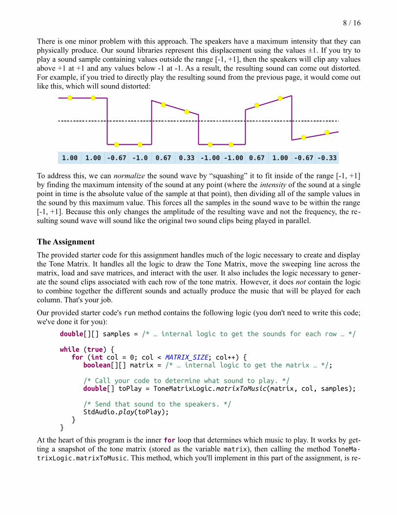
There is one minor problem with this approach. The speakers have a maximum intensity that they can physically produce. Our sound libraries represent this displacement using the values ±1. If you try to play a sound sample containing values outside the range [-1, +1], then the speakers will clip any values above +1 at +1 and any values below -1 at -1. As a result, the resulting sound can come out distorted. For example, if you tried to directly play the resulting sound from the previous page, it would come out like this, which will sound distorted:
1.00 1.00 -0.67 -1.0 0.67 0.33 -1.00 -1.00 0.67 1.00 -0.67 -0.33
To address this, we can normalize the sound wave by “squashing” it to fit inside of the range [-1, +1] by finding the maximum intensity of the sound at any point (where the intensity of the sound at a single point in time is the absolute value of the sample at that point), then dividing all of the sample values in the sound by this maximum value. This forces all the samples in the sound wave to be within the range [-1, +1]. Because this only changes the amplitude of the resulting wave and not the frequency, the re-sulting sound wave will sound like the original two sound clips being played in parallel.
The Assignment
The provided starter code for this assignment handles much of the logic necessary to create and display the Tone Matrix. It handles all the logic to draw the Tone Matrix, move the sweeping line across the matrix, load and save matrices, and interact with the user. It also includes the logic necessary to gener-ate the sound clips associated with each row of the tone matrix. However, it does not contain the logic to combine together the different sounds and actually produce the music that will be played for each column. That's your job.
Our provided starter code's run method contains the following logic (you don't need to write this code; we've done it for you):
double[][] samples = /* … internal logic to get the sounds for each row … */
while (true) { for (int col = 0; col < MATRIX_SIZE; col++) { boolean[][] matrix = /* … internal logic to get the matrix … */;
/* Call your code to determine what sound to play. */ double[] toPlay = ToneMatrixLogic.matrixToMusic(matrix, col, samples);
/* Send that sound to the speakers. */ StdAudio.play(toPlay); }}
At the heart of this program is the inner for loop that determines which music to play. It works by get-ting a snapshot of the tone matrix (stored as the variable matrix), then calling the method ToneMa-trixLogic.matrixToMusic. This method, which you'll implement in this part of the assignment, is re-
9 / 16
sponsible for generating the music that a particular column in the tone matrix will play. Our starter code then calls StdAudio.play to send the music to the speakers, which actually plays the sound.
Your task is to implement the following method in the ToneMatrixLogic class:
public double[] matrixToMusic(boolean[][] toneMatrix, int column, double[][] samples)
This method accepts as input a grid of booleans describing which lights are on in the Tone Matrix, a number representing which column in the matrix is selected, and a double[][] representing the sound clips associated with each row in the matrix. You should write this method so that it generates the sound clip for the indicated column. Specifically, your method should do the following:
1. Add together the sound samples corresponding to lit cells in the current column. This produces a single sound wave representing all the tones in the matrix. You will need to figure out how to determine which lights are turned on in the current column and how to sum up the sound sam-ples for each row.
2. Normalize the sound wave. As mentioned earlier, if you sum up multiple sound waves, you'll get back a resulting sound wave whose intensities might exceed the range [-1, +1] and therefore sound distorted when sent to the speakers. Therefore, after you've added up all the sound waves, you should normalize the sound wave so that all sound values are in the range [-1, +1]. You should only normalize the resulting sound wave after you've added together all of the sound clips. If you normalize the sound wave every time you add in a new sound clip, the resulting sound will be incorrect.
Note that you don't need to actually play the sound that you generate – our provided starter code will do that for you. You just need to create it.
Here's a more detailed breakdown of the parameters to this method.
• boolean[][] toneMatrix. This is a two-dimensional array representing the lights in the ma-trix. true values correspond to lights that are on, while false values correspond to lights that are off. The Tone Matrix is stored such that you would look up the entry at position (row, col) by reading position toneMatrix[row][col].
• int column. This integer holds the index of the column that is currently being swept across in the Tone Matrix. Your goal for this function will be to generate a sound sample for this particu-lar column, and you can ignore all the other columns in the matrix.
• double[][] samples. This two-dimensional array is actually an “array of arrays.” Each entry of the samples array is itself an array of doubles (a double[]) that holds the sound sample cor-responding to a particular row in the Tone Matrix. For example, samples[0] is the sound sam-ple that would be played by lights in row 0 of the Tone Matrix, samples[1] is the sound sam-ple that would be played by lights in row 1 of the Tone Matrix, etc. (recall that all lights in the same row as one another all play the same sound). All of these samples have length equal to the value ToneMatrixConstants.sampleSize().
Advice, Tips, and Tricks
We strongly suggest that you start off by only testing your Tone Matrix when there is at most one note playing per column. That way, you don't need to worry about normalizing the sound waves. You can test your Tone Matrix on the file diagonal.matrix, which will play every note in the matrix one after the other. For now, don't worry about getting multiple notes playing at the same time.
10 / 16
Once you can get individual notes working correctly, you can move on to getting multiple notes play-ing at the same time. To do this, you will need to combine together multiple sounds, then normalize the result. If you are successfully combining together multiple sounds but have implemented normaliza-tion, then the sounds will be distorted when you play multiple notes at the same time. As soon as you have normalization working, the sound should come out beautifully, and you can start to play around with your Tone Matrix!
Watch out for the case where no sounds are being played. In this case, you should not try to normalize your sound clip, since this would cause you to divide each entry in the sound clip (all of which will be zero) by the maximum intensity (also zero).
Part Three: Histogram Equalization
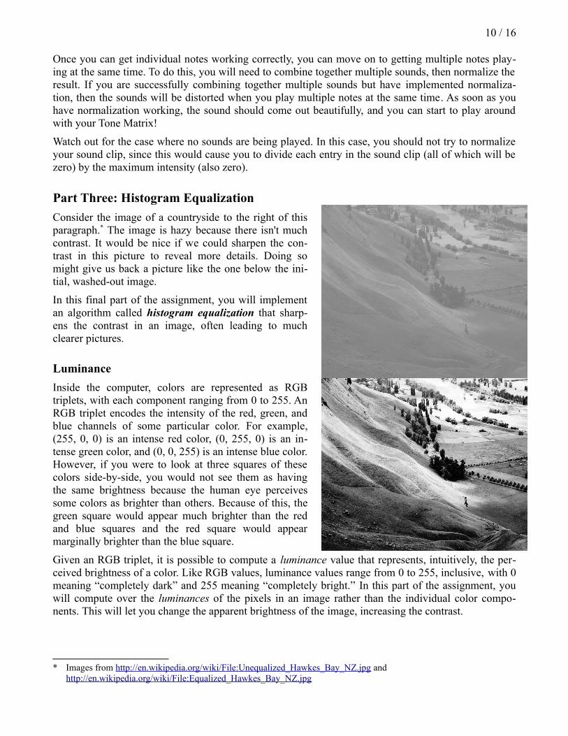
Consider the image of a countryside to the right of this paragraph.* The image is hazy because there isn't much contrast. It would be nice if we could sharpen the con-trast in this picture to reveal more details. Doing so might give us back a picture like the one below the ini-tial, washed-out image.
In this final part of the assignment, you will implement an algorithm called histogram equalization that sharp-ens the contrast in an image, often leading to much clearer pictures.
Luminance
Inside the computer, colors are represented as RGB triplets, with each component ranging from 0 to 255. An RGB triplet encodes the intensity of the red, green, and blue channels of some particular color. For example, (255, 0, 0) is an intense red color, (0, 255, 0) is an in-tense green color, and (0, 0, 255) is an intense blue color. However, if you were to look at three squares of these colors side-by-side, you would not see them as having the same brightness because the human eye perceives some colors as brighter than others. Because of this, the green square would appear much brighter than the red and blue squares and the red square would appear marginally brighter than the blue square.
Given an RGB triplet, it is possible to compute a luminance value that represents, intuitively, the per-ceived brightness of a color. Like RGB values, luminance values range from 0 to 255, inclusive, with 0 meaning “completely dark” and 255 meaning “completely bright.” In this part of the assignment, you will compute over the luminances of the pixels in an image rather than the individual color compo-nents. This will let you change the apparent brightness of the image, increasing the contrast.
* Images from http://en.wikipedia.org/wiki/File:Unequalized_Hawkes_Bay_NZ.jpg and http://en.wikipedia.org/wiki/File:Equalized_Hawkes_Bay_NZ.jpg
11 / 16
Image Histograms
Given an image, there may be multiple different pixels that all have the same luminance. An image his-togram is a representation of the distribution of luminance throughout that image. Specifically, the his-togram is an array of 256 integers – one for each possible luminance – where each entry in the array represents the number of pixels in the image with that luminance. For example, the zeroth entry of the array represents the number of pixels in the image with luminance zero, the first entry of the array rep-resents the number of pixels in the image with luminance one, the second entry of the array represents the number of pixels in the image with luminance two, etc.
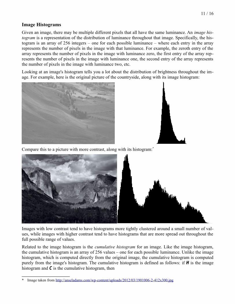
Looking at an image's histogram tells you a lot about the distribution of brightness throughout the im-age. For example, here is the original picture of the countryside, along with its image histogram:
Compare this to a picture with more contrast, along with its histogram:*
Images with low contrast tend to have histograms more tightly clustered around a small number of val-ues, while images with higher contrast tend to have histograms that are more spread out throughout the full possible range of values.
Related to the image histogram is the cumulative histogram for an image. Like the image histogram, the cumulative histogram is an array of 256 values – one for each possible luminance. Unlike the image histogram, which is computed directly from the original image, the cumulative histogram is computed purely from the image's histogram. The cumulative histogram is defined as follows: if H is the image histogram and C is the cumulative histogram, then
* Image taken from http://anseladams.com/wp-content/uploads/2012/03/1901006-2-412x300.jpg
12 / 16
C[n] = H[0] + H[1] + … + H[n]
For example, the zeroth entry of the cumulative histogram is the zeroth term of the image histogram, the first entry of the cumulative histogram is the sum of the zeroth and first terms of the image his -togram, and second entry of the cumulative histogram is the sum of the zeroth, first, and second terms of the image histogram, etc. As an example, if the first few terms of the image histogram were
2, 3, 5, 7, 11, 13, …
then the first few terms of the corresponding cumulative histogram would be
2, 5, 10, 17, 28, 41, …
One way to get an appreciation for the cumulative histogram is as follows. Given the image histogram, the nth entry of that histogram describes the total number of pixels with luminance exactly n. Given the cumulative histogram, the nth entry of that histogram describes the total number of pixels with lumi-nance less than or equal to n.
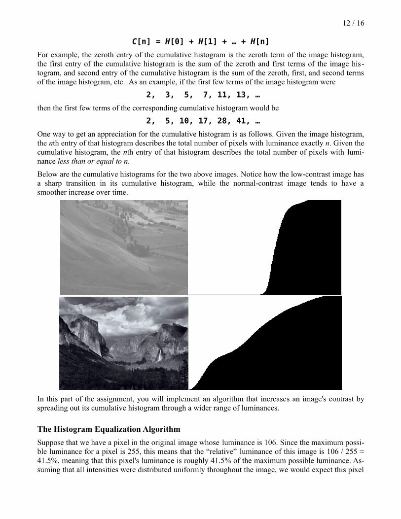
Below are the cumulative histograms for the two above images. Notice how the low-contrast image has a sharp transition in its cumulative histogram, while the normal-contrast image tends to have a smoother increase over time.
In this part of the assignment, you will implement an algorithm that increases an image's contrast by spreading out its cumulative histogram through a wider range of luminances.
The Histogram Equalization Algorithm
Suppose that we have a pixel in the original image whose luminance is 106. Since the maximum possi-ble luminance for a pixel is 255, this means that the “relative” luminance of this image is 106 / 255 ≈ 41.5%, meaning that this pixel's luminance is roughly 41.5% of the maximum possible luminance. As-suming that all intensities were distributed uniformly throughout the image, we would expect this pixel
13 / 16
to have a brightness that is greater than 41.5% of the pixels in the image. Similarly, suppose that we find a pixel in the original image whose luminance is 222. The relative luminance of this pixel is 222 / 255 ≈ 87.1%, so we would expect that (in a uniform distribution of intensities) that this pixel would be brighter than 87.1% of the pixels in the image.
The histogram equalization algorithm works by changing the intensities of the pixels in the original im-age so that if a pixel is supposed to be brighter than X% of the total pixels in the image, then it is mapped to an luminance that will make it brighter than as close to X% of the total pixels as possible. This turns out to be not nearly as hard as it might seem, especially if you have the cumulative his-togram for the image. Here's the algorithm. Suppose that an original pixel in the image has luminance L. If you look up the Lth entry in the cumulative histogram for the image, you will get back the total number of pixels in the image that have luminance L or less. We can convert this into a fraction of pix-els in the image with luminance L or less by dividing by the total number of pixels in the image:
fractionSmaller=cumulativeHistogram [ L]
totalPixels
Once we have the fraction of pixels that have intensities less than or equal to the current luminance, we can convert that fraction into a luminance value by multiplying it by 255, the maximum possible lumi-nance. The overall calculation is the following:
newLuminance=MAX_LUMINANCE⋅cumulativeHistogram [L]
totalPixels
The histogram equalization algorithm is therefore given by the following. First, compute the image his-togram for the original image. Next, compute the cumulative histogram from the image histogram. Fi-nally, replace each luminance value in the original image using the above formula.
The Assignment
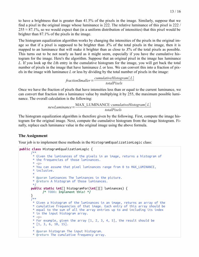
Your job is to implement these methods in the HistogramEqualizationLogic class:
public class HistogramEqualizationLogic {/** * Given the luminances of the pixels in an image, returns a histogram of * the frequencies of those luminances. * <p> * You can assume that pixel luminances range from 0 to MAX_LUMINANCE, * inclusive. * * @param luminances The luminances in the picture. * @return A histogram of those luminances. */public static int[] histogramFor(int[][] luminances) {
/* TODO: Implement this! */}/** * Given a histogram of the luminances in an image, returns an array of the * cumulative frequencies of that image. Each entry of this array should be * equal to the sum of all the array entries up to and including its index * in the input histogram array. * <p> * For example, given the array [1, 2, 3, 4, 5], the result should be * [1, 3, 6, 10, 15]. * * @param histogram The input histogram. * @return The cumulative frequency array.
14 / 16
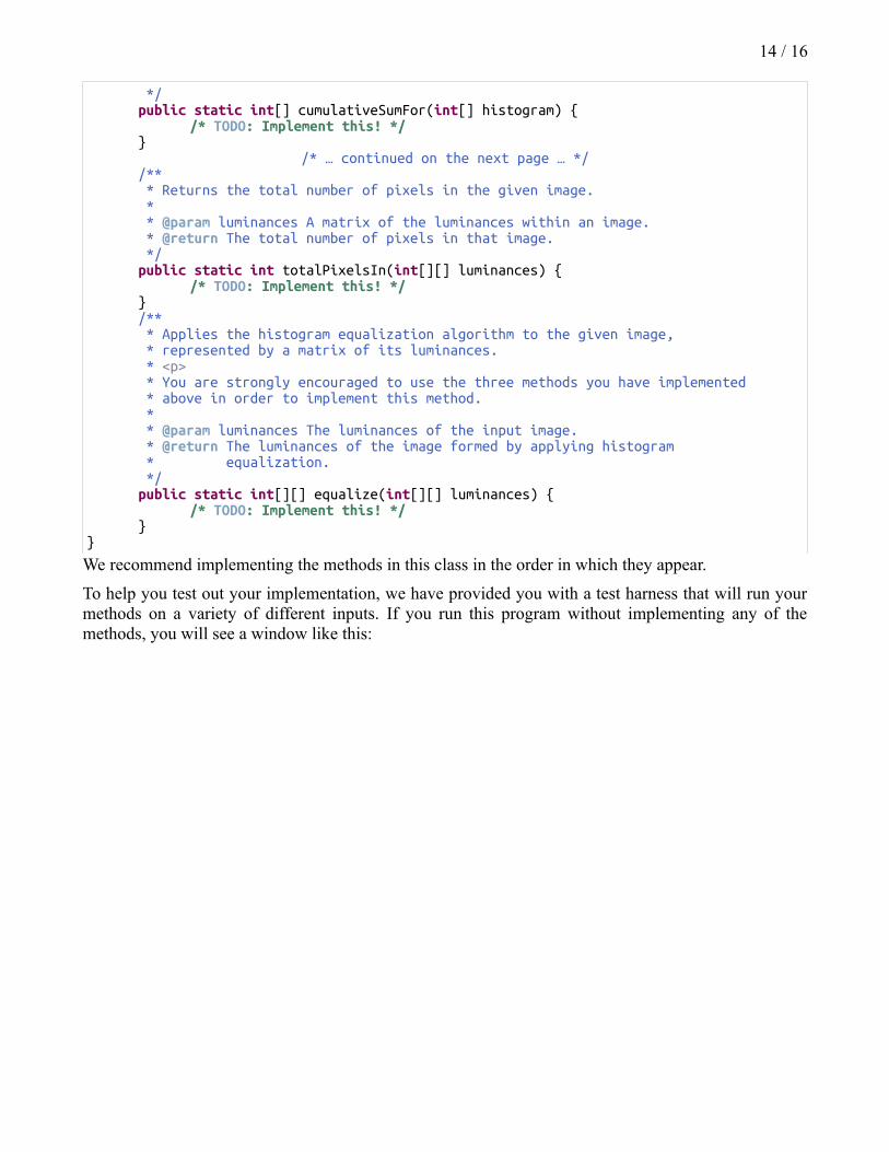
*/public static int[] cumulativeSumFor(int[] histogram) {
/* TODO: Implement this! */}
/* … continued on the next page … *//** * Returns the total number of pixels in the given image. * * @param luminances A matrix of the luminances within an image. * @return The total number of pixels in that image. */public static int totalPixelsIn(int[][] luminances) {
/* TODO: Implement this! */}/** * Applies the histogram equalization algorithm to the given image, * represented by a matrix of its luminances. * <p> * You are strongly encouraged to use the three methods you have implemented * above in order to implement this method. * * @param luminances The luminances of the input image. * @return The luminances of the image formed by applying histogram * equalization. */public static int[][] equalize(int[][] luminances) {
/* TODO: Implement this! */}
}
We recommend implementing the methods in this class in the order in which they appear.
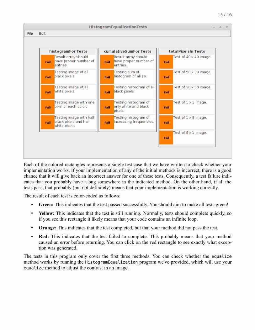
To help you test out your implementation, we have provided you with a test harness that will run your methods on a variety of different inputs. If you run this program without implementing any of the methods, you will see a window like this:
15 / 16
Each of the colored rectangles represents a single test case that we have written to check whether your implementation works. If your implementation of any of the initial methods is incorrect, there is a good chance that it will give back an incorrect answer for one of these tests. Consequently, a test failure indi-cates that you probably have a bug somewhere in the indicated method. On the other hand, if all the tests pass, that probably (but not definitely) means that your implementation is working correctly.
The result of each test is color-coded as follows:
• Green: This indicates that the test passed successfully. You should aim to make all tests green!
• Yellow: This indicates that the test is still running. Normally, tests should complete quickly, so if you see this rectangle it likely means that your code contains an infinite loop.
• Orange: This indicates that the test completed, but that your method did not pass the test.
• Red: This indicates that the test failed to complete. This probably means that your method caused an error before returning. You can click on the red rectangle to see exactly what excep-tion was generated.
The tests in this program only cover the first three methods. You can check whether the equalize method works by running the HistogramEqualization program we've provided, which will use your equalize method to adjust the contrast in an image.
16 / 16
Advice, Tips, and Tricks
We strongly recommend using our testing infrastructure when writing this program and testing as you go. Build each method independently and test them as you go. Once you think you have everything working, then try to to write the final method, which glues everything together.
Be careful with integer division and casting in the last step. You will be dividing ints by one another, so be sure not to inadvertently round all the values down.
The histogram equalization algorithm convert color images to grayscale in order to show off the high contrast. Don't worry if your results are always black-and-white; that's the expected result.
Possible Extensions
There are a huge number of possible extensions for this assignment. Here are a few suggestions to help give you some ideas:
• Steganography: You could consider using all three color channels to store hidden information, not just the red channel. This would let you hide images inside the color image that are larger than that original image, or which are not just black and white. You could also try to find a way to encode text information inside of a color picture by using multiple different pixels to store a single character.
• Tone Matrix: What kind of music could you make if you could turn the lights on in different colors, where each color played a different instrument? Or what if you changed the sound sam-ples so that the tone matrix sounded like a concert piano?
• Histogram Equalization: Could you try balancing the colors in the image, not just the lumi-nance? Can you brighten or darken the image by shifting the histogram upward or downward?
Some of these extensions might require you to make changes to some of the starter files that we pro-vide. You can download the complete source for each program from the course website and modify them to your heart's content. We've tried to make these programs as easy to read as possible, though they do use some language features we haven't discussed yet. You might want to read over Chapter 10 of The Art and Science of Java to learn more.
Writeup
Once you've finished all the coding for this assignment, we'd like you to do a quick writeup answering some questions about your experience with this assignment. Edit the writeup.txt file with your an-swers to the following questions:
1. In Histogram Equalization, the frequency histogram was represented as an int[], rather than an ArrayList<Integer>. Explain why it makes more sense to use an int[] for the histogram than an ArrayList<Integer>.
2. In this assignment, you worked with one-dimensional arrays (for histograms and sound process-ing) and two-dimensional arrays (for image processing, arrays of sound clips, and the Tone Ma-trix grid). Give an example of an application where you might want to use a three-dimensional array; for example, an int[][][]. (To clarify – you're not expected to use three-dimensional ar-rays in this assignment. We'd just like you to think about when you might use one).
Good luck!