cs 80 magneo - dormaproducts.dorma.com/.../058180-45532_0513_cs_80_magneo_documentation_gb.pdf ·...
TRANSCRIPT

CS 80 MAGNEO—
DORMA CS 80 MAGNEO
CS 80MAGNEO
CS 80 MAGNEOAUTOMATIC SLIDINGDOOR OPERATOR�
Technical DocumentationRead the manual before the assemblycarefully!

CS 80 MAGNEO—
Dear customer,
Thank you for buying a product from our product range.
The DORMA brand stands for first-class and scrutinised quality products offering extremelyhigh safety standards.
This documentation contains important information for the safe installation of the system.Please read these instructions thoroughly before you mount, install and use theCS 80 MAGNEO.
Keep these instructions for further reference and make them available to other users.
Yours faithfully,The DORMA-Team
Required tools:
Additionally for DORMA MANET fixing:
�
�
�
�
�
�
�
�
�
�
�
�
�
�
Tape measure or folding rule respectivelyWater levelPencilDrilling machineMasonry drill bit Ø 6 mmMetal drill bit Ø 3 and 8 mmSocket wrench (10 mm)Flat-bladed screwdriver for connection terminals of control unit.Crosstip screwdriver for countersunk screws of wall connection.Allen key, 4mmCombination wrench, wrench size 10 mm and 13 mmLong-nosed pliers for connection to terminals.
Adequate screws and wall plugs for the prevailing structures,in case they are not made of brickwork or concrete.
Allen key, 3 mm and 5 mm
Translation of the original documentation

REMARK
ADVISE
ATTENTION Here we will inform you of dangers that might cause damage to propertyor injure or kill people.
A remark will call your attention to important information that willfacilitate your work with the CS 80 MAGNEO.
An advice will warn you that you could damage the CS 80 MAGNEOand explain how to avoid this.
ContentsPage
1. Safety instructions 4 - 6
3. Technical data and features 9
4. System overview 10
5. Before mounting 11
6. Installation instructions for on-wall mounting 14
7. Installation instructions for in-wall mounting
11. Commissioning 31
2. Functional Characteristics 7 - 8
- 13
- 21
22 - 28
8. Connection diagrams 28
9. Cable channel 29
10. Connection of closing edge protection 30
- 32
12. Operation instructions 33 - 34
13. Commisssioning and maintenance according to DIN 18650-2, 5.1-5.4 35
14. Troubleshooting instructions 36 - 37
Manufacturer's declaration 38 - 41
Declaration of conformity 42 - 44
CS 80 MAGNEO—

CS 80 MAGNEO—
1. Safety Instructions1.1 Specified standard operation
CS 80 MAGNEO
1.2 Product-specific characteristicsneither nor
nor
1.3 Standards, laws, codes and regulations
CS 80 MAGNEO as low-energy product according to German DIN 18650(German Industrial Standard)
Reduced operating speeds (reduced dynamic forces at the door panel/contact forces)
Force limitation (reduced static forces at the door /contact forces)
Danger spots at closing edges
Required protection equipment for CS 80 MAGNEO according to DIN 18650
CS 80 MAGNEO
The is only designed to open and close
Do not allow children to play with the or rigidly mounted adjustment and/orcontrol devices. Keep remote controls out of reach of children.
.The is suitable for application in escape routes, on fire andsmoke doors on exterior doors.
According to the German Industrial Standard DIN 18650, the movement range of anautomatic door always has to be protected (amongst others) by safety sensors.However, there are special requirements for low-energy systems.The meets the requirements of a low-energy operator according to thestandard by fulfilling the following requirements:
Automatic doors might cause hazardsby crushing, shearing, hitting anddrawing-in at the differentclosing edges.
The German Industrial Standard DIN 18650 stipulates different requirements regardingthe protection of the above-mentioned danger spots.Systems with offer the following benefits:
The system does not have to be equipped with additional protection equipment (notcompulsory).The application of safety sensors at the closing edges as additional protection measure isoptional and lies in the discretion of the person performing the installation of the doorsystem - under consideration of the result of the individual risk assessment (please alsorefer to “Risk assessment”, page 4).Altogether the system offers a high safety standard!
small and light interior doorswith an admissible weight from 20 kg to 80 kg per door panel.
A door kit is provided to make the connection with the door leaf.
Automatic doors might cause hazards by crushing, shearing, hitting and drawing-in.Depending on the structural conditions, the door version and the safety equipment,residual risks cannot be excluded.
CS 80 MAGNEO
CS 80 MAGNEO
Residual risks
CS 80 MAGNEO
panel
�
�
�
�
�
Mainclosing edgeSecondary
closing edge

Safety requirements according to DIN 18650 in the Full Energy mode
www.dorma-magneo.com
CS 80 MAGNEO
The actuating forces are also limited in this mode. However, due to the higher contactforces that can occur, a safety kit must be installed. This must be done by a specialist inaccordance with DIN 18650 or equivalent national safety regulations.
Risk assessment on the part of the installer
Special requirements regarding the protection of people in need of protection
1.4 Limitation of liabilityCS 80 MAGNEO
DORMA GmbH + Co. KG
1.5 DocumentationUsing control elements, making adjustments or performing procedures that are notdescribed herein might cause electric shocks, danger caused by electric voltage/currentand/or dangers due to mechanical incidents.It is important for your personal safety to abide by the instructions mentioned in thisdocumentation. An incorrectly performed installation of the system might cause seriousinjuries.
1.6 General information regarding the installation of the systemThe CS 80 MAGNEO must be disconnected from power supply (de-energized) whenperforming mounting or installation work. Remove the power plug, or, in case ofpermanent power supply, switch off fuse.
Special spatial conditions and certain user groups might make it sensible to equip theapplication with safety sensors – even when the system is operated in Low-Energy-Mode.Whether this is required or not has to be assessed with the aid of an individual riskassessment and must be considered during the planning of the system and by themanufacturer, i.e. the party performing the installation of the system.We would therefore ask you to have a look at our “risk assessment form”, which isavailable on our homepage and will help you to perform the riskassessment.
In case the risk assessment reveals that there is a health risk or risk of injury when thedoor hits a user in an unacceptable way, additional protection via safety equipment(connection of safety sensors) is required. This is especially necessary when people inneed of protection (children, elderly people or disabled people) use the door.These safety devices must be installed by a specialist in accordance with DIN 18650 orequivalent national safety regulations.
The must only be used according to its specified standard operation.will not accept any liability for damages resulting from
unauthorized modifications of the .
Please keep this documentation for later reference.
Secure the working area against unauthorized access of other people.Falling items or tools might cause injuries.In any case, the way of mounting and the mounting equipment, like for example screwsand wall plugs, have to be adequate with regard to the structural conditions (concrete,wood, plasterboard etc.)
�
�
CS 80 MAGNEO—

CS 80 MAGNEO - Awarded safety
Developed according to the latest safety standards:Low-Energy-Mode in accordance with DIN standard
Tested Safety- mark
The TÜV certificate and the certificate can be obtainedfrom the manufacturer on demand.
CS 80 MAGNEO—
�
�
As soon as you have relaxed the screws of the end stop, both the end stop and the carriercould fall out of the operator. Therefore you should always hold the operator straight.
Pay attention that no water or other liquids drop on or into the .
The carrier contains strong permanent magnets and must not be removed.
Never stick metal objects inside the openings of the .Otherwise you could sustain an electric shock.
Never put you hand inside the in order to avoid injuries.
Only specially qualified staff may open the power supply housing.Lay the power cord so that nobody can trip over the cable or unplug it by mistake.
Do not operate the when the power cord is damaged.
Always pull at the plug and never at the cable when unplugging the power supply.Only operate the mains switch at the header profile while the door stands still or ispermanently open.No pushbuttons/switches, pictures etc. must be located within the door's movementrange. Baseboards have to be removed if required.Following the successful installation of the system, you have to check the settings as wellas the and the safety devices for proper functioning.
The installation described herein is only an example. Structural or local conditions,available tools or other conditions might suggest a different approach.
�
�
�
�
�
�
�
�
�
�
�
CS 80 MAGNEO
CS 80 MAGNEO
CS 80 MAGNEO
CS 80 MAGNEO
CS 80 MAGNEO
� This device must not be disposed of as domestic waste.

2. Functional Characteristics2.1 General information
2.2 Commissioning
2.3 Energy modes
Low-Energy-Mode (Standard)
Full-Energy-Mode
The is a single-panelelectromechanical sliding door operator forsmall and light interior doors with anadmissible weight from 20 kg to 80 kg perdoor panel. The opening and closing speedrespectively depend on the weight of thedoor panel and can be adjusted via apotentiometer (infinitely variable).
During the first commissioning of theoperator, the facility operator has to performa learning cycle according to thecommissioning instructions. When thefacility operator connects the system to thepower supply (plugs it in) the light indicatorat the operator will blink and the operatorhas no function. The door can be openedand closed manually. Following the learningcycle the light indicator goes on and theoperator is ready for operation.
With the aid of a sealed switch (locatedinside the operator), the system can beswitched from Low-Energy-Mode to Full-Energy-Mode (mandatory installation ofsafety devices).
According to the standard (DIN 18650) theforce with which a door panel hits anobstacle must be limited when a system isoperated in Low-Energy-Mode. Therefore theoperator moves the door panel atcorrespondingly low speed and no additionalsafety sensors are required. Thepotentiometer (located inside the operator)can only be used to reduce the speed.
The forces are limited in this mode as well.Due to the increased contact forces, safetyequipment is compulsory in most cases.
CS 80 MAGNEOThe speed is infinitely variable with the aidof a potentiometer (located inside theoperator).The closing cycle always remains in Low-Energy-Mode.
The operator is switched off.You can move the door byhand.
When the system has beenactivated via pushbutton,radio remote control or similar,the operator opens the doorand closes it on expiry of theadjusted hold-open time.
The operator opens the doorand holds it in "open" positionuntil it receives another signal.
When the system is delivered, theis adjusted to AUTOMATIC
Mode.
As soon as the door is moved manually intoopening direction by approximately 10 mm,the operator will automatically move the doorpanel further in the desired direction. Thedoor closes automatically.
A double-click on the pushbutton (activatethe pushbutton twice in quick succession)will open the door. When you double-click onthe button for a second time or move thedoor panel by hand, the door will close.
As soon as you push the button or move thedoor manually the door will open. When youpush the button for a second time or movethe door panel by hand, the door will close.
2.4 Operation modes
2.5 Functions in AUTOMATIC ModePush & Go
Permanent Open via double-click
Opening/closing via pushbutton
OFF:
AUTOMATIC:
PERMANENTOPEN:
CS 80 MAGNEO
An external program switch is requiredto change the operation mode.
CS 80 MAGNEO—

CS 80 MAGNEO—
Express-Function
2.6 Safety functionsStatic forces in Low-Energy-Mode
Opening cycle
Closing cycle
The door can be moved manually in istoperational direction and there will be noextra resistance. However, when themaximum speed is exceeded, the operationalresistance will increase in line with thespeed by which it is exceeded. As soon asthe user has released the door panel, theoperator will softly slow it down to maximumspeed. This function is activated during allopening and closing cycles.
The system does not exceed a value of 67 Nduring opening and closing cycles.
As soon as the door hits an obstacle duringan opening cycle, it will immediately stopand remain in its position for 3 seconds.Then the operator will try to continue theopening cycle. If the door panel hits anobstacle three times during an openingcycle, it will close.
When the door panel hits an obstacle whileclosing, it will immediately stop and performan opening cycle.
2.7 Safety sensors
2.8 Power failure
You can install sensors to detect obstacles.According to DIN 18650, an automaticsensor test can be activated or deactivatedvia the DIP switches located inside theoperator.The door will stop immediately when thesensor detects an obstacle during anopening cycle and will continue the cycle assoon as the obstacle has been removed. Incase the obstacle is not removed, the doorwill close on expiry of the adjusted hold-open time.The door will stop immediately and reversewhen the sensor detects an obstacle duringan closing cycle. This function is notactivated while the door is in "closed"position (then the sensor is deactivated).
In the event of a power failure, the door canbe opened and closed by hand.
As soon as the voltage returns, the operatorwill automatically perform a positioninitialization.
However, in this case the operator doesnot slow down (brake) the door panel, sothat the user has to move (hold) it allthe way by hand.
During this position initialization, it isessential that the movement range ofthe door is free of obstacles.

max. movement rangeOperator lengthwithout cover
Weight of operator
875 mm
1000 mm
1125 mm
1750 mm
2000 mm
2250 mm
8.6 kg
9.4 kg
10.2 kg
Power supply:
Power consumption without external accessories:
General information:
Power supply: 220 – 230 V AC ±10%; 50/60 HzFuse protection (by others): 10 ACable type: max. 3 x 1.5 mm²
Stand-By-Mode: 3.7 WAutomatic-Mode: max. 60 W
Temperature range: 0-40° COperating noise of operator: max. 55 dB (A)Door panel height: max. 3000 mmDoor panel weight: 20 kg - 80 kg
Weight of operator:
3. Technical data and features
CS 80 MAGNEO—

8
7
6
5
4
3
2
1ON
DIP switch LEDlight indicator
Potentiometerhold-open time
Connection terminals forexternal accessories
Mains switchEnergy mode switch(Full-Energy/Low-Energy)(located below the seal)
Potentiometerspeed
Reset buttonStartlearning cycle
CS 80 MAGNEO—
Actuated opening direction
4. System overview
Control unit and connection terminals for external accessories
Power supplyCS 80 MAGNEO
Control unit and connectionterminals for external accessories

max. 2200 mm
01462 477 602GBPlease call the following number in caseof technical problems or further questions:
5. Before mountingBasic requirements:
Work on electrical equipment may only be performed by properly qualified staff(electricians).
When the system is installed with permanent power supply (the cable comes directly outof the wall), ensure that the power supply line is dead (de-energized) during installation.
The power supply line, max. 3 x 1.5 (Schuko-type shockproof socket or permanentpower supply) must have a 10 A fuse protection.
Opening direction:
Please note:
�
�
�
�
The floor has to be level.Glass door panels have to be made of safety glass.The connection cables for external accessories (program switch etc.) must be located inthe close range of the operator before starting the installation of the system.With in-wall mounting, the wall must not be closed before the system has been mounted.
The connections of the operator are always located on the side where the door is when itis in “closed” position.
Therefore the operator is symmetrical and can be turned the way you require it.This installation instructions show the system with connection on the right side.Thus the installation with connection on the left side is realised laterally reversed.
In case you require additional accessories, please contact your local dealer.If you have technical questions or require help during the installation of the system, pleasecontact our hotline under the following number:
mm2
The cable of the power supply line has alength of 2.5 m. Thus a Schuko-typeshockproof socket (230 V AC, 50/60 Hz)must be available within this distance.
When installing the socket, pleaseremember that you should be able toreach it by hand.
For in-wall mounting:
CS 80 MAGNEO—

60 mm
60
mm
min. 2
50mm
1.
2.
1.
2.
4.1.
5.2.
Installation with permanent power supply:When the system is installed with permanentpower supply, the internal power supplysocket has to be removed.Proceed as follows:Relax the screws at the end stop and movethe end stop to the centre of the system.
Do not remove or screw down the endstop.
In order to facilitate the cabling insidethe operator, all cables should have alength of at least 250 mm.
If you want all connection cables that arecoming out of the wall not to be seen afterthe installation (only possible withpermanent power supply), they have to comeout of the wall within an area of 60 x 60 mmon the side where the connections of theoperator are located.
For on-wall mounting:
Then relax the screw in the cover of thepower supply housing and remove the cover(on the side where the connections arelocated).
Keep the cover and the screw in a safeplace as you will require it later.
CS 80 MAGNEO—

1.1.
3.
2.
Open the cover of the control unithousing by levering it out with thetip of a screwdriver.
careful
flat-bladed
Relax the screws of the connection terminalsand remove the internal Schuko-typeshockproof socket.
Then close the cover of the control unithousing.Move the end stop to the end of the channeland screw it down.
The end stop must not overlap.
CS 80 MAGNEO—

Mainclosing edgeSecondary
closing edge
L 1750 2000 2250
L/4 437.5 500 562.5
875 1000 1125
==
Ref
eren
celin
e
Main closing edge
L/4
6. Installation instructions for on-wall mounting
Reference lines for positioning purposes.
For the installation without shim plate
For the installation with shim plate
L
Mark the centre of the passage on the wall.
Mark the centre of the passage on the wall.Please have a look at the table for therequired dimension for your operator.
corresponds to the operator length.
L/4
Now mark the reference line.Always mark the reference line on the side ofthe main closing edge.
In case the door panel shall not bepositioned in the centre of the passage,the bracket or shim plate has to beshifted by the desired dimension.
Mounting procedure
1. Auxiliary lines for positioning purposes
2.a Installation without shim plate
2.b Installation with shim plate
3. Further installation
If there is a door frame, you have to shim the angle brackets withthe shim plate (optional).
See bottom of this page.
See Page 15 and 16.
See Page 17.
See Page 18 – 21.
CS 80 MAGNEO—

L
C
X
6 m
m
L 1.750 2.000 2.250
C 575 700 825
= =
Passage width (PW)
PW 810 935 1.060
Projectionmax. 65 mm
Projection
875 1.000 1.125
Ref
eren
celin
eS
ide
wit
hco
nnec
tion
s
“Closed” position
50 mm
�
�
The "closed" position is always locatedon the side where the connections are.Dimension L (Length of operator andfixing bracket) is measured without endcaps.
Take dimension from floor level; thenposition and mark the upper edge of thefixing bracket onto the wall.
X
The distance between the bottom edgeof the door panel and the floor shouldamount to 6 mm, however, it must notexceed 8 mm.
With
With glass clamping rail:= Door panel height + 114 mm
= Door panel height + 74 mm
wooden door panel:X
Dimension X has to be measuredat the highest point of the floorwithin the movement range ofthe door system.
= Door panel height + 78 mm
With DORMA MANETsingle-point fixings
X
X
CS 80 MAGNEO—

Center lineBefore drilling the holes, check if thereare cables or pipes in the close range ofthe drill holes.
Use adequate wall plugs and screwsdepending on the prevailing structurewhen fixing the bracket.The supplied screws and wall plugs aresuitable for concrete and brickwork.
The load-bearing capacity of the fixingbracket must amount to at least 240 kg.
Position the fixing bracket onto the centreline.Ensure that the bottom vertex of the triangleis located exactly on the centre line.Align the fixing bracket so that it is level.Fix the bracket with screws(one screw respectively per one oblong holeon each side).
Recheck the fixing bracket for exactpositioning.Drill the further holes through the drill holesin the fixing bracket and fix the bracket withat least 12 screws.
In case of uneven walls you have to shim thebracket so that it does not bend.Use the enclosed distance plates in differentsizes for this purpose.
CS 80 MAGNEO—

Reference lineMounting with shim plate
Door panel height + 78 mm
Door panel height + 74 mm
Before drilling the holes, check if thereare cables or pipes in the close range ofthe drill holes.
Use adequate wall plugs and screwswith respect to the prevailing structure.
The supplied screws and wall plugs aresuitable for concrete and brickwork.
The load-bearing capacity of the fixingbracket must amount to at least 240 kg.
Position the shim plate at the reference line.Calculate the dimension from the floor to theupper edge of the shim plate as follows:
When using DORMA MANET single-pointfixings:
Align the shim plate so that it is level andmark the drill holes.
Drill the marked holes and fix the shimplate.
In case the frame is ticker than 10 mm,you have to underlay the shim platewith the enclosed distance plates sothat it is flush with the door frame.
Use 12 screws to fix the bracket to the shimplate.
CS 80 MAGNEO—
60 mm

6x
2.
3.4.
1.
L1N
35 mm
6 mm
6 mm
150 mm
L1
N
Lever out the cover at the control unithousing with the aid of a screwdriver.Lay the grounding line through the housingof the operator as shown in the picture andconnect it to the grounding terminal (PE).
Connect all external accessories but thesafety sensors.Please refer to the instructions for the cablechannel on page 26.
The grounding (PE) has to be connectedin any case.
Connection of 230 V permanent power supply
Work on electrical equipment may onlybe performed by properly qualified staff(electricians).Before starting with the installation,make sure that the power supply line isdead (de-energized).
Relax the end stop and move it to the centreof the system (see page 11, picture in themiddle).Cut the leads to length, dismantle them andconnect L1 and N to the connectionterminals of the power supply.
1.
2..
3.
4.
.
Adhere 3 pieces of felt equally ontothe bracket.The openings of the door panelsuspension have to point to the frontWhen using MANET fixings, the doorpanel suspensions have to beunscrewed.Fix the operator below the bracket with6 hexagon screws (lock screws) .
You will have to move the carrier inorder to reach all 6 holes
(8 Nm)
CS 80 MAGNEO—

1.
2.
3.
The distance between door panel andwall must not exceed 8 mm.
Inser the panel into the door panelsuspension as indicated in the picture, alignit so that it is parallel to the wall and screwit down.
When using MANET fixings, please considerthe instructions enclosed with the MANETfixings.
Close the cover of the control unit housing.Fix and screw down the cover of the powersupply housing.Move the end stop to the end of the channeland screw it down thoroughly (see page 13,picture at the bottom).
CS 80 MAGNEO—
max. 8 mm

6 m
m
3.
3.
2.
Y
4.1.
Y
Locate and fix the provided floor guide rail.Please consider the mounting instructions ofthe doorkit.
When adjusting the floor guide you haveto make sure that the door panel runssmoothly through the floor guide (doesnot rub against the floor guide).
Align the door panel with the aid of theadjustment nuts so that it is level.
The distance between the bottom edgeof the door panel and the floor shouldamount to 6 mm, however, it must notexceed 8 mm.
Relax the screws of the end stop on the sidewhere the connections are and move thedoor to the desired “closed” position. Movethe end stop next to the door panel andscrew down tight (5 Nm).
The end stop may only be moved to theinside by a certain dimension.
875 mm operator => max. 200 mm1000 mm operator => max. 250 mm1125 mm operator => max. 300 mm
The end stop must not overlap at the outeredge.
CS 80 MAGNEO—

1.2.
3.
3.
Y
2.1.
Y
4.
Fix the DORMA logo in the two drill holes.
Please install radio receivers, programswitches and/or sensors and lay the cablesas indicated in the enclosed instructions.
Insert the end caps into the cover.
Depending on the prevailing structuralconditions, the end caps can either becut to length or broke out at thepredetermined breaking points.
When the system is operated with a powerplug, plug it in.
1. Adhere the 4 provided pieces of foamrubber equally onto the operator.
2. Fix the black wall connection profiles atthe bottom of the operator on the sidewhere it is connected to the wall. Cutthe last profile to length with the aid ofa knife.
3. Place the cover onto the operator andclip it shut. When using DORMAMANET single-point fixings, you have touse the shorter cover (displayed on theright side).
Continue with the commissioning of thesystem as indicated starting from page 31.
Relax the screws of end stop on the otherside and move the door to the desired“open” position. Move the end stop next tothe door panel and screw down tight (5 Nm).
The end stop may only be moved to theinside by a certain dimension.
The end stop must not overlap at the outeredge.
875 mm operator => max. 200 mm1000 mm operator => max. 250 mm1125 mm operator => max. 300 mm
CS 80 MAGNEO—

C
L
A = at least L + 120 mm
min. 50 mm min. 70 mm
“Closed” position
Side withconnections
6 m
m
Bottom edge of lintel
X
min
d. 7
0 m
m ==
L/4With
With glass clamping rail:= Door panel height + 111 mm
= Door panel height + 71 mm
wooden door panel:X
Dimension X has to be measuredat the highest point of the floorwithin the movement range ofthe door system.
= Door panel height + 75 mm
With DORMA MANETsingle-point fixings
X
X
L 1750 2000 2250
A
C
mind. 1870
575
mind. 2120
700
mind. 2370
825
L/4 437.5 500 562.5
CS 80 MAGNEO—
The wall must not be closed before thesystem has been installed.
The connections should always be onthe side where the door panel is whenthe door is in “closed” position.
Dimension stands for the operatorlength.
Dimension indicates the distancefrom the centre of the passage area tothe side of the operator where theconnections are located.The distance between the door paneland the floor should amount to 6 mmand must not exceed 8 mm.
�
�
�
�
L
L/4
The holes for the cables must besufficiently big and must not have sharpedges.
Please have a look at the table and thedrawing for the dimensions regarding youroperator.
7. Installation instructions for in-wall mounting

43
Then move the operator over the fixingbracket as far as it will go.
Align the operator so that it is parallel to thewall.
Make sure to position the operatorcorrectly, i.e. the side with theconnections must be opposite the fixingbracket.
Never leave the operator on the fixingbracket without holding it in position asthis would deform the fixing bracket.
Draw a further line at a distance of 43 mm.Then position the fixing bracket at thesecond line and mark the drill holes.Drill the holes and fix the fixing bracket withadequate screws.
Hold the operator in the desired position andmark the end of the operator on the sideopposite the connections.
CS 80 MAGNEO—

Then mark the fixing holes through the holesin the operator.
Remove the operator and drill fixing holeswith a diameter of 4.2 mm for the suppliedsheet metal screws.The sheet metal must at least be 2 mmthick and the subconstruction must at leastcarry 240 kg.
In order to reach all 4 holes, you have tomove the carrier.
Fix the operator under the cross girder withthe selected screws.
The operator has to be fixed so that it isexactly level and parallel to the wal.
All connection cables have to be laid inthe close range of the operator at thispoint.
The holes for the cables must besufficiently big and must not have sharpedges.
Then move the operator over the fixingbracket as far as it will go.
The side with the connections must beopposite the fixing bracket.
Never leave the operator on the fixingbracket without holding it in position asthis would deform the fixing bracket.
The openings of the door panelsuspension have to point to the front asyou cannot turn them following theinstallation of the system.
CS 80 MAGNEO—

1.
2.
3.
L1N
35 mm
6 mm
6 mm
150 mm
L1
N
Connection of 230 V permanent power supply
Work on electrical equipment may onlybe performed by properly qualified staff(electricians).Before starting with the installation,make sure that the power supply line isdead (de-energized).
Relax the end stop and move it to the centreof the system (see page 12, picture in themiddle).Cut the leads to length, dismantle them andconnect L1 and N to the connectionterminals of the power supply.
Close the cover of the control unit housing.Fix and screw down the cover of the powersupply housing.Move the end stop to the end of the channeland screw it down thoroughly (see page 13,picture at the bottom).
Lever out the cover at the control unithousing with the aid of a screwdriver.Lay the grounding line through the housingof the operator as shown in the picture andconnect it to the grounding terminal (PE).
Connect all external accessories but thesafety sensors.Please refer to the instructions for the cablechannel on page 29.
The grounding (PE) has to be connectedin any case.
CS 80 MAGNEO—

Insert the door panel into the door panelsuspension, align it so that it is parallel tothe wall and screw it lightly down.
Move the door to “open“ position, then fixthe provided floor guide in the properposition.Please consider the mounting instructions ofthe doorkit guide.
When adjusting the floor guide you haveto make sure that the door panel runssmoothly through the floor guide (doesnot rub against the floor guide)
Screw the door panel down.
Move the end stop to the end of the channel.
Place the door panel inside the door frame.As the door panel is wider than the doorway,you will have to tilt it.
The end stop must not fall out of theoperator.
As it will be difficult to get hold of thedoor panel with in-wall mounting, youshould use wooden wedges to help youto lift the door panel.
CS 80 MAGNEO—

Y
3.
Y
2.1.
Y
4.
3.
3.
2.
Y
4.1.
Y
6 m
m
Align the door panel with the aid of theadjustment nuts so that it is level.
The distance between the bottom edgeof the door panel and the floor shouldamount to 6 mm, however, it must notexceed 8 mm.
Relax the screws of end stop on the otherside and move the door to the desired“open” position. Move the end stop next tothe door panel and screw down tight (5 Nm).
The end stop may only be moved to theinside by a certain dimension.
The end stop must not overlap at the outeredge.
875 mm operator => max. 200 mm1000 mm operator => max. 250 mm1125 mm operator => max. 300 mm
Relax the screws of the end stop on the sidewhere the connections are and move thedoor to the desired “closed” position. Movethe end stop next to the door panel andscrew down tight (5 Nm).
The end stop may only be moved to theinside by a certain dimension.
875 mm operator => max. 200 mm1000 mm operator => max. 250 mm1125 mm operator => max. 300 mm
The end stop must not overlap at the outeredge.
CS 80 MAGNEO—

CS 80 MAGNEO—
max. 8 mm max. 8 mm
94
9596
1
3
1
315
313
1
342
3
31
334
1
311
313
1
341
3
Power supply for externalaccessories 27 V DC, max. 700 mA
8. Connection diagrams (Only for properly qualified staff!)
door close contact
Locking deviceLocking device
+27 V DCGNDAutomaticGNDPermanent open
Internal activator inside(e.g. radar motion detector / pushbutton)
External activator(e.g. radar motion detector / pushbutton)
Program switch (optional)Remove jumper before a program switchwill be installed
Safety sensor for secondary closing edgeRemove jumper before a sensorwill be installed
Safety sensor for main closing edgeRemove jumper before a sensorwill be installed
Connection terminals
In order to facilitate the connection of thewires, the different terminal blocks can beremoved with pointed pliers.
+27 V DCGND
GNDSafety sensor test+27 V DCGND
GNDSafety sensor test+27 V DCGND
GND+27 V DCGND
GND
The distance between door panel andwall must not exceed 8 mm.
The clearance has to be covered withbrushes or similar, if required.
Please install radio receivers, programswitches and/or sensors and lay the cablesas indicated in the enclosed instructions.Continue with the commissioning of thesystem as indicated starting from page 31.
connector Locking device
locking cable
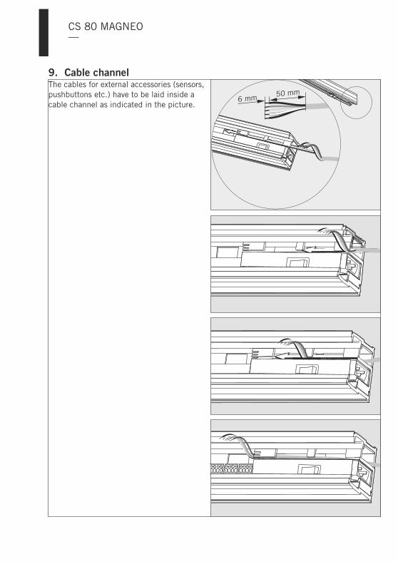
The cables for external accessories (sensors,pushbuttons etc.) have to be laid inside acable channel as indicated in the picture.
9. Cable channel
CS 80 MAGNEO—
50 mm6 mm

8
7
6
5
4
3
2
1ON
8
7
6
5
4
3
2
1ONDIP switch
CS 80 MAGNEO—
10. Connection of closing edge protectionThis work may only be performed by properly qualified staff.
When a sensor is connected to the main closing edge
When a sensor is connected to the secondary closing edge
When sensors are connected to the main and secondary closing edge
When testable sensors for the protection of the closing edges are connected, the control unithas to be adjusted to the sensors via the DIP switches.
Set DIP switch 1 to ON and DIP switch 3 to OFF.
Set DIP switch 2 to ON and DIP switch 3 to OFF.
Set DIP switch 1 and 2 to ON and DIP switch 3 to OFF.
3 ONOFF
OFF
OFF
= test high active= test low active
sensor test for secondary closing edge activatedsensor test for secondary closing edge deactivated
sensor test for main closing edge activated= sensor test for main closing edge deactivated
2 ON
1 ON
==
=

hold open time /Offenhaltezeit
speed /Geschwindigkeit
Basic requirementsCS 80 MAGNEO
General information
CS 80 MAGNEO
Learning cycle
�
�
�
�
�
The is completelymounted.You can move the door smoothly overthe complete movement range.
When you connect the system to the powersupply (plug it in) the green light indicatorblinks and the operator has no function. Youcan access the door manually.In order to make the operator ready foroperation, you have to perform a learningcycle.The green LED goes on following the learningcycle. The is now ready foroperation and operates in Low-Energy-Mode.
This "approach" describes the commissioningof the standard door system. Accessories anddifferent operation modes can be adjustedafter the system has been commissioned.Sensors are connected and adjustedfollowing the successful commissioning ofthe system.The light indicator (LED) will give you visualfeedback.The settings stored during the commissioningof the system can be overwritten byperforming a new commissioning.
In order to start the learning cycle:The door must be open.The operator must be switched on.The movement range of the door mustbe free of obstacles.
The green LED will blink before the firstlearning cycle.
Apart from during commissioning, alearning cycle has to be performed everytime the position of an end stop hasbeen adjusted or the weight of the doorhas changed.
Press and hold the "Reset" button for morethan 3 seconds.
Do not interrupt the learning cycle asthe system currently learns all values itrequires.
During the learning cycle the door will:
The CS 80 MAGNEO is now ready foroperation.
How to switch the system from Low-Energy-to Full-Energy-Mode
Only authorized staff (authorization onthe part of DORMA required) mayswitch the CS 80 MAGNEO toFull-Energy-Mode. As there are higherforces in Full-Energy-Mode, the closingedges have to be protected by safetysensors.
Speed adjustment
Adjustment of hold-open time
Open twice and close again. The LED willblink green at certain intervals then it willshow a permanent green light.
Therefore we do not explain how to switchthe system to Full-Energy-Mode in theseinstructions.
The maximum speed depends onthe weight of the door panel. Youcan reduce the speed with the aidof the potentiometer (infinitelyvariable).
The door will close automaticallyon expiry of the adjusted hold-open time following it hasreached "open" position. You canadjust the hold-open timeinfinitely from 5 to 30 secondswith the aid of the potentiometer.
Only use the enclosed red screwdriverto perform potentiometer adjustments!
11. Commissioning
CS 80 MAGNEO—

8
7
6
5
4
3
2
1ON
87654321
ON
DIP switch LEDlight indicator
Potentiometerhold-open time
Connection terminals forexternal accessories
Mains switchPotentiometerspeed
Reset buttonStart learning cycle
CS 80 MAGNEO—
87
6
5
4
3
2
1
OFF = No locking function ON = Locking functionOFF = Reduced closing force ON = Enhanced closing force
OFF = Automatic Function activated ON = Permanent Open Function activated
OFF = External motion detector activated ON = External pushbutton activated
OFF = Internal motion detector activated ON = Internal pushbutton activated
OFF = Test low active ON = Test high active
OFF = Sensor test at secondary closing edge deactivatedON = Sensor test at secondary closing edge activated
OFF = Sensor test at main closing edge deactivatedON = Sensor test at main closing edge activated
DIP switch settingsYou can activate different inputs at the connection terminals via theseswitches and thus adjust different operation modes.
Permanent Open Function via double-clickThis function can only be adjusted when apushbutton is connected.In order to activate this function, DIPswitches 4 and 5 at the control unit have tobe set to “ON” position.
This function is only available withpushbutton or Push & Go Function.In order to activate it, DIP switches4, 5 and 6 have to be set to "ON" position.
Opening/closing via pushbutton
Closing forceIn case the door does not close properly dueto the door seals, you can increase the forcewith which the operator presses the dooragainst the seal.In order to do so, set DIP switch 7 to “ON”position.

hold open time /Offenhaltezeit
speed /Geschwindigkeit
87654321
ON
87654321
ON
1. Opening the door in AUTOMATICFunction
CS 80 MAGNEO
Push & Go
Pushbutton:
Sensors:
PERMANENT OPEN via double-click
Opening/Closing via pushbutton
When the system is delivered, theis adjusted to AUTOMATIC
Function. Depending on the installedaccessories, the door can be opened indifferent ways.
As soon as the door is moved manually intoopening direction by approximately 10 mm,the operator automatically moves the doorpanel further in the desired direction.The door closes automatically.
Following the activation of the pushbutton(e. g. wall-mounted pushbutton or radiotransmitter) the operator opens and closesthe door.
Where presence sensors (radar motiondetectors or similar) are connected, the dooropens automatically as soon as a personapproaches the door system.The door closes automatically.
When this function is activated, the door canbe opened permanently by double-clickingthe pushbutton. In order to close the door,a further double-click on the pushbutton isrequired.To activate this functionset
As soon as you push the button or move thedoor manually the door will open. When youpush the button for a second time or movethe door panel by hand, the door will close.
DIP switchto position.
To activate this functionset DIP switchto position.
4 and 5ON
4, 5 and 6ON
Express-Function
2. In the event of a power failure
3. Adjustments
Speed adjustment
Adjustment of hold-open time
The door can be moved manually along itsoperational path without extra resistance.When the maximum speed is exceeded, theoperational resistance will increase in linewith the speed by which it is exceeded.As soon as the user has released the doorpanel, the operator will softly slow it down tomaximum speed. This function is activatedduring all opening and closing cycles.
In the event of a power failure, the door canbe opened and closed by hand.
However, in this case the system doesnot brake the door panel, which meansthat the user has to move (hold) it allthe way by hand.
As soon as the voltage returns, the operatorwill automatically perform a positioninitialization.
During this position initialization, themovement range of the door has to befree of obstacles.
Only use the enclosed red screwdriverto perform potentiometer adjustments!
The maximum speed depends onthe weight of the door panel. Youcan reduce the speed with the aidof the potentiometer (infinitelyvariable).
The door will close automaticallyon expiry of the adjusted hold-open time following it hasreached “open” position. You canadjust the hold-open timeinfinitely from 5 to 30 secondswith the aid of the potentiometer.
12. Operating instructions
CS 80 MAGNEO—

1
2
3PERMANENT OPEN
OFF
AUTOMATIC
PERMANENT OPEN
OFF
AUTOMATIC
CS 80 MAGNEO—
4. Closing force
5. Internal program switch (optional)
In case the door does not close properly dueto the door seals, you can increase the forcewith which the operator presses the dooragainst the seal.In order to do so, set DIP switch 7 to "ON"position.
The internal program switch (if available) isinstalled in the lateral cover on the sidewhere the door is when "closed".
In order to change the operation mode, justadjust the program switch to the desiredfunction.
Changing the operation mode
6. Program switch EPS-S3 (optional)
Changing the operation mode
1-1-1-1.
Power failure
The EPS-S3 is secured via an individuallyadjustable 4-digit code.1. Unlock the EPS-S3 by entering in the
code.Original setting =The last 4 digits always count.In case you entered an incorrect code,just retype the correct code.The is unlockedThe LED for the current operating modeblinks.
2. Adjust the desired operation mode byactivating the respective button.The LED of the selected operation modelights up.
The EPS-S3 locks automatically 1 minuteafter its last activation.
Following a power failure, the EPS-S3 isadjusted to the operation mode that hasbeen activated before the power failure.
�
�
EPS-S3
If the inputs for Permanent Open(terminal 34) and Automatic (terminal 31)are connected in parallel behind GND(terminal 3), the system operates inPermanent Open mode. This allows forexample connecting a key switch to ensureproper fire brigade access or an emergencyopening pushbutton parallel to a programswitch.
�
7. Emergency opening

13. Commisssioning and maintenance according to DIN 18650-2, 5.1-5.4According to DIN 18650, the following points have to be observed:
An inspection and acceptance test according to the below-mentioned checklist has to beperformed before the first commissioning of the system by trained staff (trained byDORMA).Regular maintenance and inspections have to be performed (at least once a year) underconsideration of our specifications for the by properly trained staff.
Documentation of the results in accordance with DIN 18650-2 paragraph 5.1-5.4.The facility operator has to keep the properly filled-out checklist according to ourspecifications for at least 1 year.
The system has been installed properly in accordance with the instructions of themanufacturer.
The door panels run smoothly/have been readjusted (if required).
The door works properly (check the opening and closing cycle respectively).
Function of installed activators like radar motion detectors, pushbuttons or remotecontrols has been checked.
The contactless safety equipment (safety sensors), if installed, has been checked forproper function.
Effective safety equipment has been installed to avoid or protect danger spots betweencertain parts of the door system and between the door and its structural environment (likefor example safety clearances or the protection of the secondary closing edges).
Test badge has been fixed.
The inspection and maintenance work has been documented.
The has to be switched off and secured against unintended and unauthorizedswitching on before performing maintenance work (cleaning or maintenance).
Only use commercial cleaning agents to clean the operator.Scrubbing cleansers might damage (scratch) the surface of the operator
�
�
�
CS 80 MAGNEO
Checklist (start-up test, maintenance, regular inspections) according to DIN 18650-2,paragraph 5.1-5.4
CS 80 MAGNEO
Care
.
CS 80 MAGNEO—

11. Troubleshooting instructionsMalfunctionThe door does notrespond.The green LED lightindicator is off.
The door does notrespond.The green LED lightindicator is on.
The green LED lightindicator blinks atcertain intervals.The door stops duringa cycle.
The door movesbeyond the adjusted“open” or “closed”position.The red LED lightindicator illuminatespermanently.The red LED lightindicator blinks twiceat certain intervals.The red LED blinks 3times at regularintervals.
Possible causeNo power supply.Loose cable connections.
Damaged power cord.Damaged power plug.The program switch is set to(OFF).The program switch is set to(Permanent Open).The door has been adjusted toPermanent Open Function viadouble-click.The safety sensors at the doorare activated (there is somethingwithin the detection range of thesensor).Damaged sensor cable.
No safety sensors are connected.The operator is defective.The learning cycle has not beenperformed properly.
The door does not run smoothly.
The corresponding end stop hasshifted its position.
Defective control unit.
Defective control unit.
The power mode switch of thedoor has been switched toanother position.
The operator is defective.
[0]
[II]
RemedySwitch on mains switch.Connect cable connectionsthoroughly.Replace power cord.Replace operator.Set the program switch to thedesired function.Set the program switch to thedesired function.Close door via double-click.
Remove obstacles. Adjust safetysensors if required.
Check and replace cables ifrequired.Check and replace jumpers ifrequired.Terminals must be bridged.Replace operator.Restart learning cycle (Page 31).
Check movement range andremove cause for unsmoothrunning.Check guide rail and floor guidefor dirt or wear and clean orreplace if required.Readjust end stop and tightenscrews.
Switch mains switch off and on.Replace operator.
Switch mains switch off and on.Replace operator.
Switch mains switch off and on.
Replace operator.
Start learning cycle (Page 31).
CS 80 MAGNEO—

01462 477 602GBPlease call the following number in caseof technical problems or further questions:
MalfunctionThe red LED blinks 4times at regularintervals.
The red LED blinks 5times at regularintervals.
The red LED blinks 6times at regularintervals.
The red LED blinks 10times at regularintervals.
Humming noise whiledoor is in endposition.The door panelvibrates when moving.
Possible causeTestable safety sensors aredefective.Damaged sensor cable.
DIP switches 1 to 3 are not setcorrectly.Incremental encoder or cable ofincremental encoder is defective.The opening width is adjustedincorrectly.
There is an obstacle within thedoor’s movement range.The opening width has beenadjusted incorrectly.
Stator or cable of stator isdefective.
Short circuit at the terminalconnection.
Inappropriate end position ofdoor panel.
The guide mechanism is undertension.
RemedyCheck and replace safety sensorsif required.Check and replace cables ifrequired.Check settings of DIP switchesand readjust if required.Switch mains switch off and on.Replace operator.Readjust opening width(end stops).
Remove obstacles frommovement range.Readjust opening width (endstops).Start learning cycle (Page 31).Switch mains switch off and on.Replace operator.
Start learning cycle (Page 31).
1. Remove the short circuit.2. The operator has to be
switched off and then on withthe aid of the mains switch.
Shift end stop by at least 2 mm.Start learning cycle (Page 31).
Readjust the door panelconnection and the floor guide ifrequired. Turn the nuts severaltimes in order to fix the doorpanels.
Operating cycle indicatorWhen you press the "Reset" button on the control unit for a short time, the door will open. Incase the LED light indicator lights up for one second (yellow light), the system has performedmore than 200,000 cycles.You should contact the Service Department in order to have the system checked.
In case a defective operator has to be replaced, please contact your authorised dealer at therespective point of purchase with the respective proof of purchase. However, you have toconsider that the complete basic operator including carriers has to be returned
CS 80 MAGNEO—
CS 80 MAGNEO—
EC Declaration of incorporation

CS 80 MAGNEO—
EC Declaration of incorporation

CS 80 MAGNEO—
EC Declaration of incorporation

CS 80 MAGNEO—
EC Declaration of incorporation

CS 80 MAGNEO—
EC Declaration of conformity

CS 80 MAGNEO—
EC Declaration of conformity

CS 80 MAGNEO—
EC Declaration of conformity

CS 80 MAGNEO—

CS 80 MAGNEO—

CS 80 MAGNEO—

CS 80 MAGNEO—
WN
05
81
80
45
53
2,
05
/13
,·S
ubje
ct t
o ch
ange
wit
hout
not
ice
DORMA GmbH + Co. KGDORMA Platz 158256 ENNEPETALDEUTSCHLANDTel. +49 2333 793-0Fax +49 2333 793-4950www.dorma.de