cs 430/536 computer graphics i 3d viewing week 6, lecture 12
DESCRIPTION
CS 430/536 Computer Graphics I 3D Viewing Week 6, Lecture 12. David Breen, William Regli and Maxim Peysakhov Geometric and Intelligent Computing Laboratory Department of Computer Science Drexel University http://gicl.cs.drexel.edu. Overview. 3D Viewing 3D Projective Geometry - PowerPoint PPT PresentationTRANSCRIPT
1
CS 430/536Computer Graphics I
3D ViewingWeek 6, Lecture 12
David Breen, William Regli and Maxim Peysakhov
Geometric and Intelligent Computing Laboratory
Department of Computer Science
Drexel Universityhttp://gicl.cs.drexel.edu

2
Overview• 3D Viewing• 3D Projective Geometry• Mapping 3D worlds to 2D screens• Introduction and discussion of
homework #4
Lecture Credits: Most pictures are from Foley/VanDam; Additional and extensive thanks also goes to those credited on individual slides
1994 Foley/VanDam/Finer/Huges/Phillips ICGPics/Math courtesy of Dave Mount @ UMD-CP

3
Recall the 2D Problem
• Objects exist in a 2D WCS• Objects clipped/transformed to viewport• Viewport transformed and drawn on 2D screen
Pics/Math courtesy of Dave Mount @ UMD-CP

4
From 3D Virtual World to 2D Screen
• Not unlike The Allegory of the Cave (Plato’s “Republic", Book VII)
• Viewers see a 2D shadow of 3D world
• How do we create this shadow?
• How do we make it as realistic as possible?
Pics/Math courtesy of Dave Mount @ UMD-CP

5
History of Linear Perspective
• Renaissance artists– Alberti (1435)– Della Francesca (1470)– Da Vinci (1490)– Pélerin (1505)– Dürer (1525)
Dürer: Measurement Instruction with Compass and Straight Edge
http://www.handprint.com/HP/WCL/tech10.html
6
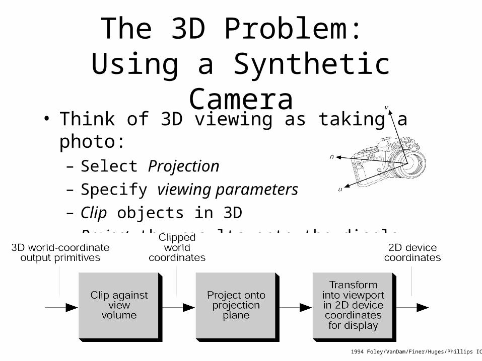
The 3D Problem: Using a Synthetic Camera
• Think of 3D viewing as taking a photo:– Select Projection– Specify viewing parameters– Clip objects in 3D– Project the results onto the display and draw
1994 Foley/VanDam/Finer/Huges/Phillips ICG

7
The 3D Problem: (Slightly) Alternate Approach
• Think of 3D viewing as taking a photo:– Select Projection– Specify viewing parameters– Perform trivial accept/reject test in 3D– Project the results onto the image plane– Clip lines to world window– Transform to viewport and draw

8
Creating a 3D View:Parameterizing the Camera
Basic Ideas:• Camera has
– location– lens (focal length)– projection type
• World has– lights– colors– objects (visible and hidden
surfaces)
1994 Foley/VanDam/Finer/Huges/Phillips ICG

9
Planar Geometric Projections
• Projections onto Planes– Consider the line AB
• Perspective Projection– a single viewing location– similar to a photograph
• Parallel Projection– viewing location at – good for capturing shape
and dimensions
1994 Foley/VanDam/Finer/Huges/Phillips ICG
∞
10
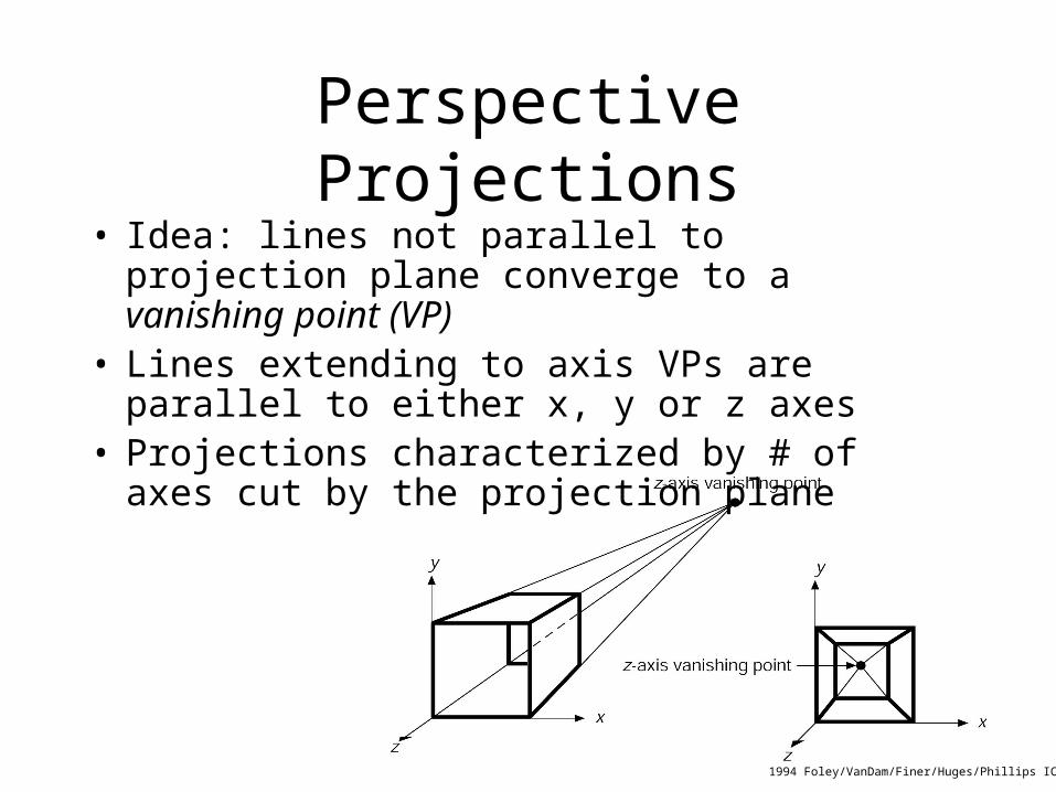
Perspective Projections• Idea: lines not parallel to projection plane
converge to a vanishing point (VP)• Lines extending to axis VPs are parallel to
either x, y or z axes• Projections characterized by # of axes cut by
the projection plane
1994 Foley/VanDam/Finer/Huges/Phillips ICG
11
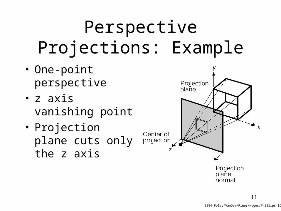
Perspective Projections: Example
• One-point perspective
• z axis vanishing point
• Projection plane cuts only the z axis
1994 Foley/VanDam/Finer/Huges/Phillips ICG

12
Perspective Projection (Titanic)

13
Perspective Projections: Example
• Two-point perspective, cutting x and z• Used commonly in CAD• Three-point projections
are not much different
1994 Foley/VanDam/Finer/Huges/Phillips ICG
14
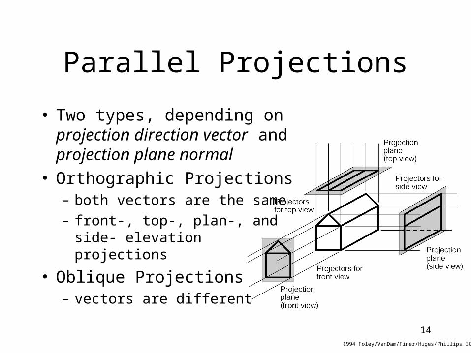
Parallel Projections
• Two types, depending on projection direction vector and projection plane normal
• Orthographic Projections– both vectors are the same– front-, top-, plan-, and side-
elevation projections
• Oblique Projections– vectors are different
1994 Foley/VanDam/Finer/Huges/Phillips ICG

15
Mercury Spacecraft

16
Axonometric Orthographic Projections
• Projections to planes not normal to principle coordinate axes, i.e. showing several faces
• The Isometric Projection– very common– projection plane at equal
angles to each of the coordinate axes
– 8 of them, one in each octant
1994 Foley/VanDam/Finer/Huges/Phillips ICG

17
Mercury Spacecraft

18
Oblique Projections
• Projection direction and Projection plane normal differ
• Preserves certain angles and distances
• Good for use in illustration and measurement
1994 Foley/VanDam/Finer/Huges/Phillips ICG
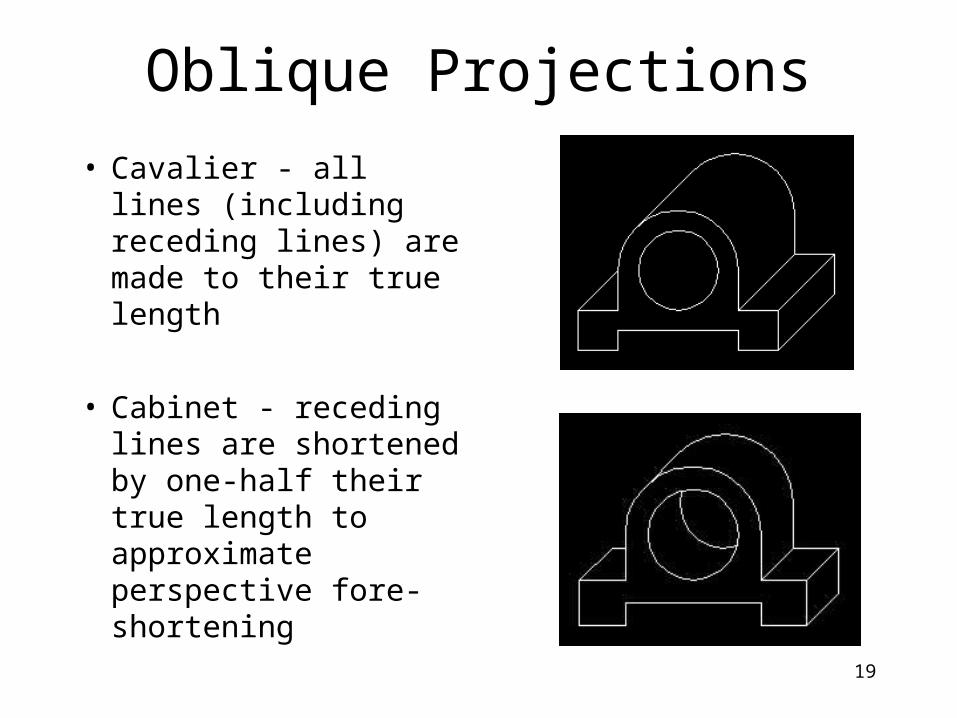
Oblique Projections
• Cavalier - all lines (including receding lines) are made to their true length
• Cabinet - receding lines are shortened by one-half their true length to approximate perspective fore-shortening
19
20
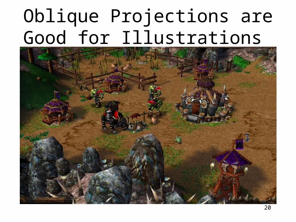
Oblique Projections are Good for Illustrations

21
Projection Relationships
• As the distance to the projection point moves toward infinity, the two projection families unify
– Projection plane– Direction to center of
projection– Distance to CoP
1994 Foley/VanDam/Finer/Huges/Phillips ICG

22
Specification of 3D Views
• Projection Plane == View Plane– defined as a view reference point (VRP)
and a view plane normal (VPN)– View up vector (VUP) defines “up” on the plane
(so we can orient axes on to the plane)
1994 Foley/VanDam/Finer/Huges/Phillips ICG
23
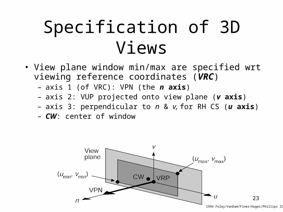
Specification of 3D Views
• View plane window min/max are specified wrt viewing reference coordinates (VRC)– axis 1 (of VRC): VPN (the n axis)– axis 2: VUP projected onto view plane (v axis)– axis 3: perpendicular to n & v, for RH CS (u axis) – CW: center of window
1994 Foley/VanDam/Finer/Huges/Phillips ICG
24
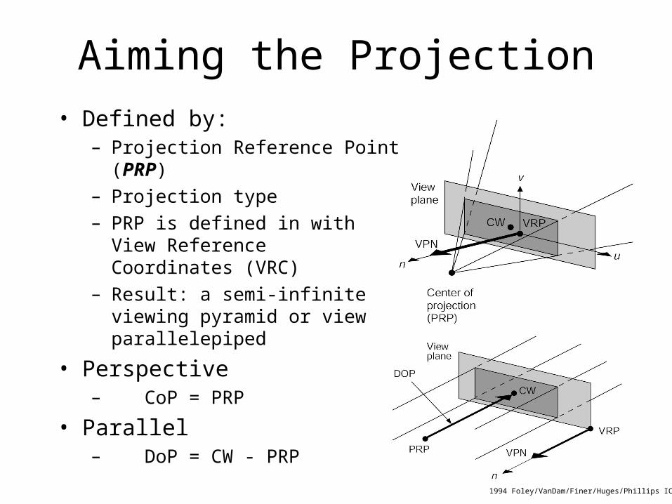
Aiming the Projection• Defined by:
– Projection Reference Point (PRP)– Projection type– PRP is defined in with
View Reference Coordinates (VRC)
– Result: a semi-infiniteviewing pyramid or viewparallelepiped
• Perspective– CoP = PRP
• Parallel– DoP = CW - PRP
1994 Foley/VanDam/Finer/Huges/Phillips ICG

25
Defining the View Volume
• What portion of the world do we view?– where do we start?– how far back to go?
• View Volume– front clipping plane– back clipping plane
• For perspective, things far away gets smaller
1994 Foley/VanDam/Finer/Huges/Phillips ICG
26
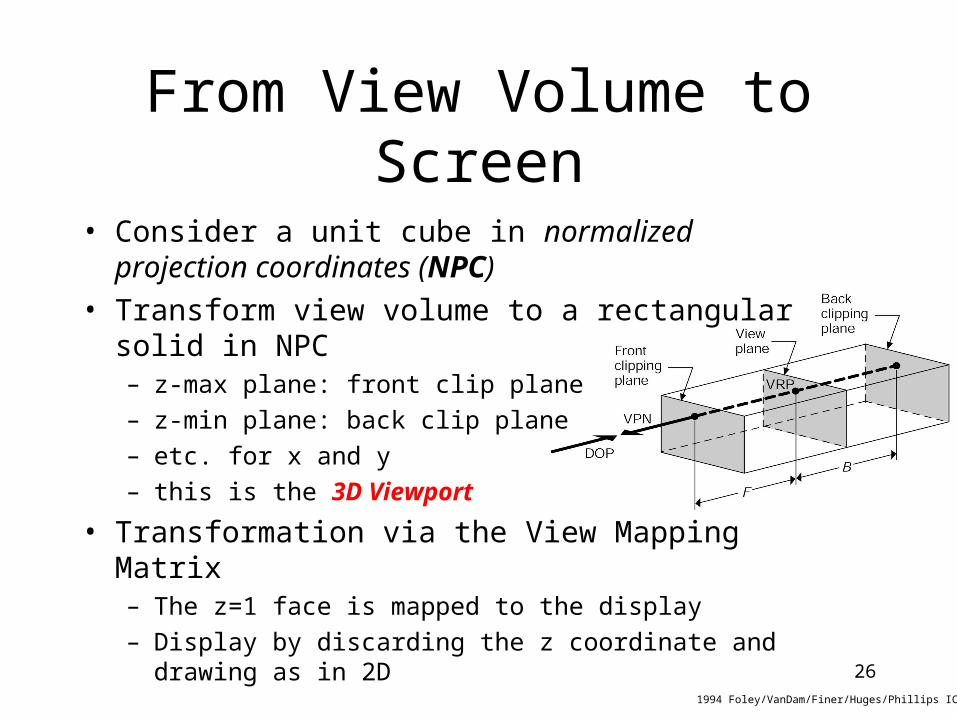
From View Volume to Screen
• Consider a unit cube in normalized projection coordinates (NPC)
• Transform view volume to a rectangular solid in NPC– z-max plane: front clip plane– z-min plane: back clip plane– etc. for x and y– this is the 3D Viewport
• Transformation via the View Mapping Matrix– The z=1 face is mapped to the display– Display by discarding the z coordinate and drawing as
in 2D1994 Foley/VanDam/Finer/Huges/Phillips ICG

27
Parameter Summary• Viewing
Parameters:– VRP (WC)– VPN (WC)– VUP (WC)– PRP (VRC)
– {u,v}min, {u,v}max
– CW (VRC)– F & B (VRC)– projection type
• What the parameters mean:– View Reference Point– View Plane Normal– View Up Vector– Projection Reference Point– Window extent– Center of Window– Front and Back clipping planes– perspective/parallel
28
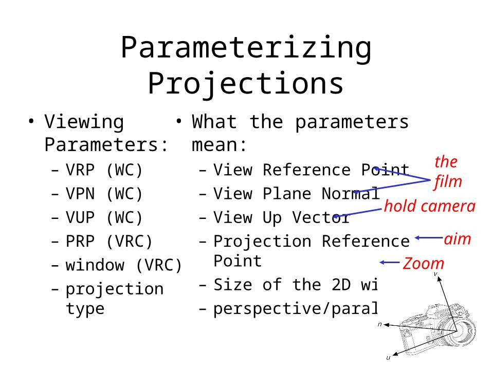
Parameterizing Projections
• Viewing Parameters:– VRP (WC)– VPN (WC)– VUP (WC)– PRP (VRC) – window (VRC)– projection type
• What the parameters mean:– View Reference Point– View Plane Normal– View Up Vector– Projection Reference Point– Size of the 2D window– perspective/parallel
thefilm
hold camera
aim
Zoom

29
Examples of 3D Viewing: Preliminaries
• Dimensions and location of a simple house
• Two-point perspective projection of the house
1994 Foley/VanDam/Finer/Huges/Phillips ICG

30
Examples of 3D Viewing: Preliminaries
• Default viewing specification– x,y,z coincides with
u,v,n– Window bounds from
0 to 1
1994 Foley/VanDam/Finer/Huges/Phillips ICG

31
Examples of 3D Viewing: Preliminaries
• Default parallel projection view volume– cuboidal
1994 Foley/VanDam/Finer/Huges/Phillips ICG
32
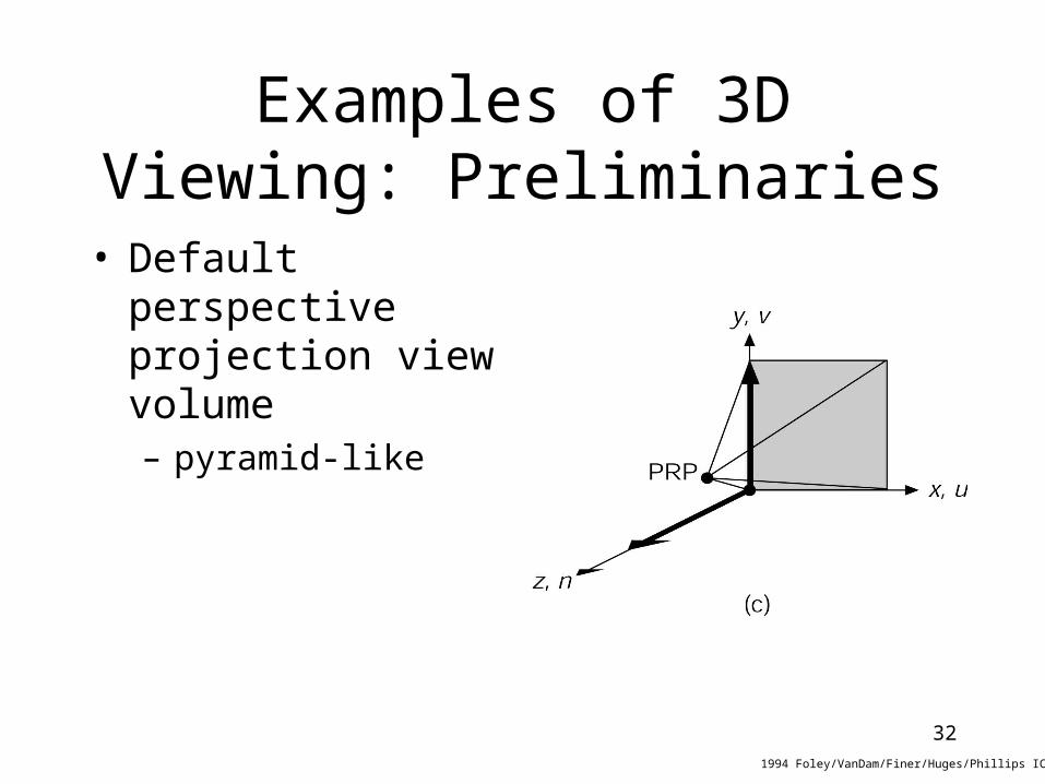
Examples of 3D Viewing: Preliminaries
• Default perspective projection view volume– pyramid-like
1994 Foley/VanDam/Finer/Huges/Phillips ICG
33
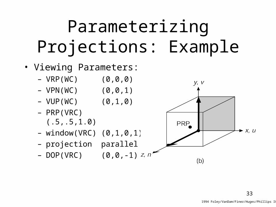
Parameterizing Projections: Example
• Viewing Parameters:– VRP(WC) (0,0,0)– VPN(WC) (0,0,1)– VUP(WC) (0,1,0)– PRP(VRC) (.5,.5,1.0)– window(VRC) (0,1,0,1)– projection parallel– DOP(VRC) (0,0,-1)
1994 Foley/VanDam/Finer/Huges/Phillips ICG

34
Perspective Projections: Example
• Parameters:– VRP(WC) (0,0,0)– VPN(WC) (0,0,1)– VUP(WC) (0,1,0)– PRP(VRC) (8,6,84)– window(VRC) (-50,50,-50,50)– projection perspective
1994 Foley/VanDam/Finer/Huges/Phillips ICG

35
Perspective Projections: Example (centering)
• Parameters:– VRP(WC) (0,0,54)– VPN(WC) (0,0,1)– VUP(WC) (0,1,0)– PRP(VRC) (8,6,30)– window(VRC) (-1,17,-1,17)– projection perspective
1994 Foley/VanDam/Finer/Huges/Phillips ICG
36
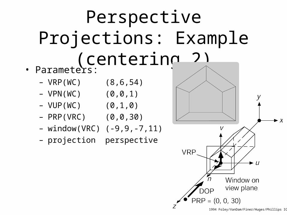
Perspective Projections: Example (centering 2)
• Parameters:– VRP(WC) (8,6,54)– VPN(WC) (0,0,1)– VUP(WC) (0,1,0)– PRP(VRC) (0,0,30)– window(VRC) (-9,9,-7,11)– projection perspective
1994 Foley/VanDam/Finer/Huges/Phillips ICG
37
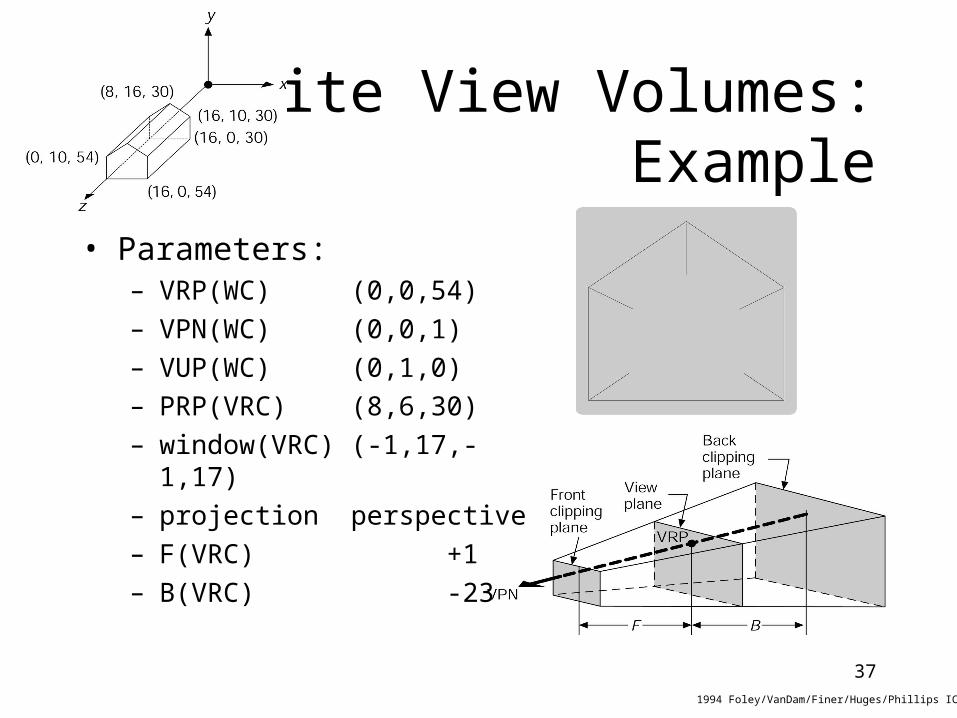
Finite View Volumes:Example
• Parameters:– VRP(WC) (0,0,54)– VPN(WC) (0,0,1)– VUP(WC) (0,1,0)– PRP(VRC) (8,6,30)– window(VRC) (-1,17,-1,17)– projection perspective– F(VRC) +1– B(VRC) -23
1994 Foley/VanDam/Finer/Huges/Phillips ICG
38
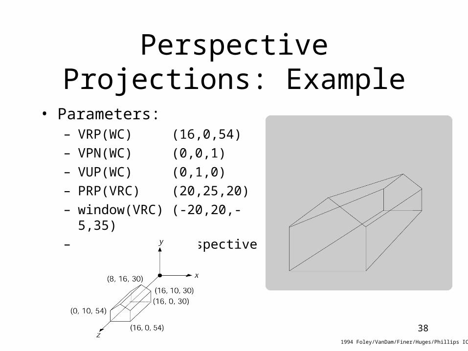
Perspective Projections: Example
• Parameters:– VRP(WC) (16,0,54)– VPN(WC) (0,0,1)– VUP(WC) (0,1,0)– PRP(VRC) (20,25,20)– window(VRC) (-20,20,-5,35)– projection perspective
1994 Foley/VanDam/Finer/Huges/Phillips ICG

39
Perspective Projections: Example
• Parameters:– VRP(WC) (16,0,54)– VPN(WC) (1,0,1)– VUP(WC) (0,1,0)– PRP(VRC) (0,25, )– window(VRC) (-20,20,-5,35)– projection perspective
1994 Foley/VanDam/Finer/Huges/Phillips ICG
220

41
Perspective Projections: Example (cont.)
• Showing the object relative to the view plane, w/ overhead view
1994 Foley/VanDam/Finer/Huges/Phillips ICG
42
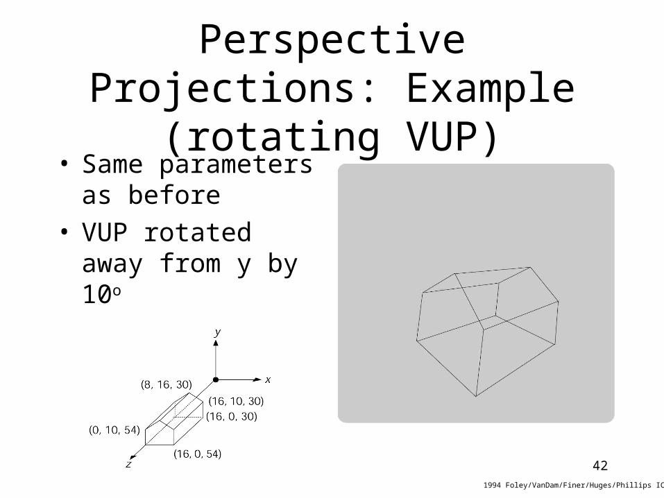
Perspective Projections: Example (rotating VUP)
• Same parameters as before
• VUP rotated away from y by 10o
1994 Foley/VanDam/Finer/Huges/Phillips ICG
43
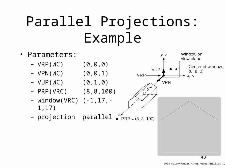
Parallel Projections:Example
1994 Foley/VanDam/Finer/Huges/Phillips ICG
• Parameters:– VRP(WC) (0,0,0)– VPN(WC) (0,0,1)– VUP(WC) (0,1,0)– PRP(VRC) (8,8,100)– window(VRC) (-1,17,-1,17)– projection parallel

44
Programming assignment 4
• Read SMF file
• Implement parallel projection
• Implement perspective projection
• Output projected and clipped polygon edges