crystal river unit #3 containment delamination ... · pdf filecontainment delamination...
TRANSCRIPT

Crystal River Unit #3Containment Delamination
Investigation & Repair
March 9, 2010Garry Miller

• CR#3 Containment Design Features• SGR Opening Sequence & Identification of Delamination• Investigative Approach• Condition Assessment• Operational Experience (OE)• Root Cause Analysis (RCA)• Design Basis Analysis (DBA)• Repair Sequence• Summary Comments / Questions
Agenda
2

CRYSTAL RIVER #3 DESIGN FEATURES
3
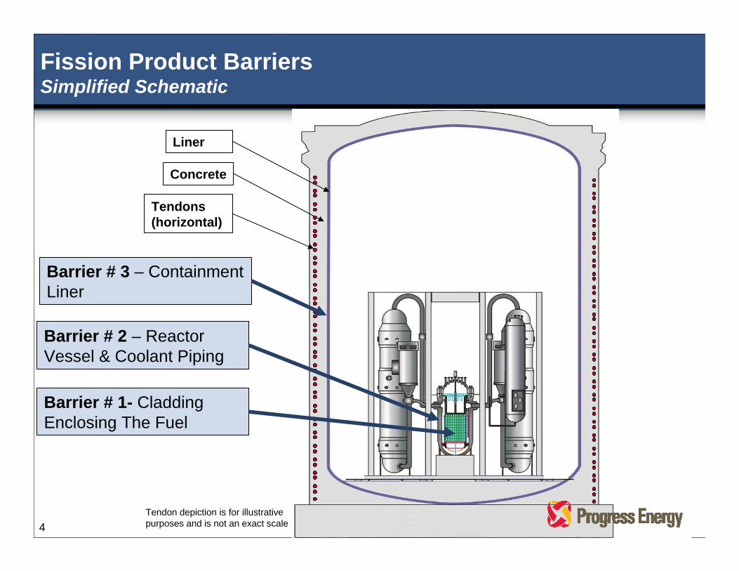
Fission Product BarriersSimplified Schematic
Liner
Concrete
Tendons(horizontal)
Barrier # 1- Cladding Enclosing The Fuel
Barrier # 2 – Reactor Vessel & Coolant Piping
Barrier # 3 – Containment Liner
Tendon depiction is for illustrativepurposes and is not an exact scale 4
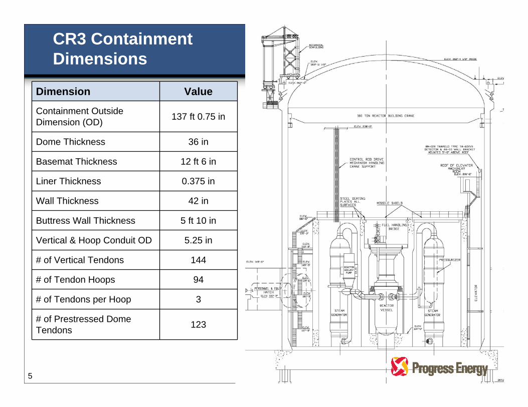
Dimension Value
Containment Outside Dimension (OD) 137 ft 0.75 in
Dome Thickness 36 in
Basemat Thickness 12 ft 6 in
Liner Thickness 0.375 in
Wall Thickness 42 in
Buttress Wall Thickness 5 ft 10 in
Vertical & Hoop Conduit OD 5.25 in
# of Vertical Tendons 144
# of Tendon Hoops 94
# of Tendons per Hoop 3
# of Prestressed Dome Tendons 123
CR3 Containment Dimensions
5

SGR OPENING SEQUENCE & IDENTIFICATION OF
DELAMINATION
6

Steam Generator Replacement (SGR) Opening (between Buttresses 3 and 4)
7
SGR OpeningDimensions
@ Liner23’ 6” x 24’ 9”
@ Concrete Opening25’ 0” x 27” 0”

Concrete Removal
8

Concrete & Liner Removal Sequence
1 2
3 4
9

Delamination Close-up
10

Location of the Delamination
11
Note - Tendon depiction is for illustrativepurposes and is not an exact scale
INVESTIGATION APPROACH
12
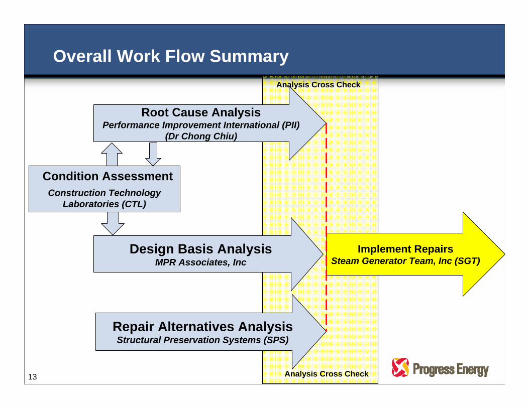
Root Cause AnalysisPerformance Improvement International (PII)
(Dr Chong Chiu)
Design Basis AnalysisMPR Associates, Inc
Repair Alternatives AnalysisStructural Preservation Systems (SPS)
Analysis Cross Check
Implement RepairsSteam Generator Team, Inc (SGT)
Overall Work Flow SummaryAnalysis Cross Check
Condition AssessmentConstruction Technology
Laboratories (CTL)
13

• Condition Assessment & Laboratory Testing• NDT - Construction Technology Laboratories (CTL)• Labs - MacTec, Soil& Materials Engineers (S&ME)• Other Field Data - Sensing Systems, Inc; Core Visual Inspection
Services (Core VIS), Nuclear Inspection & Consulting, Inc; Precision Surveillance; Gulf West Surveying Inc; AREVA
• Root Cause Analysis• Lead - Performance Improvement International (PII)
• Numerous PhD's (11) with expertise in root cause investigation techniques, nuclear engineering, nuclear operations & maintenance, material science & testing, concrete standards & construction, concrete testing, concrete creep, concrete fracture, human performance, process analysis, containment analysis, reliability and computer modeling
• Owner’s Support - Worley Parsons, Bechtel
External Support
14
• Design Basis Analysis• Lead - MPR Associates, Inc.• Owner’s Support - Worley Parsons
• Repair Alternatives Analysis• Lead - Structural Preservation Systems (SPS)• Owner’s Support - Wiss, Janney, Elstner, Inc (WJE)
• Industry Peer Support• Exelon, SCANA, and Southern Company
External Support (cont)
15

Nuclear Safety Oversight Committee (NSOC)Containment Sub-Committee Membership
Member Title
John Elnitsky (PGN) VP - Nuclear Plant Development (Chairman)
Joe Donahue (PGN) VP - Nuclear Oversight
Chris Burton (PGN) VP - Harris
Greg Selby Technical Director - EPRI
Dr. Shawn Hughes VP - Shaw Stone & Webster
Dr. Paul Zia Civil Engineering Professor, NCSU
Hub Miller 33 years industry oversight experience
Darrell Eisenhut 41 years industry operation and oversight experience
16

CONDITION ASSESSMENT
17
• Determine Extent of Condition• Characterize the extent of delamination at the SGR opening• Determine condition of other portions of structure
• Non-Destructive Testing (NDT) of Containment Wall Surfaces• Use of Impulse Response (IR) Method• Comprehensive on external exposed surfaces• Accessible areas in adjacent buildings
Condition Assessment Activities
18

• Concrete Cores• Used to confirm IR results (over 116 cores)• Visual examination of core bore holes with boroscope to identify if
delamination present
• ASME Section XI IWL Visual Inspection (affected areas)
• Containment Dome Inspections• NDT IR scans in segment above the SGR opening • Concrete cores with boroscope examination of bore holes• Physical survey with established benchmarks
Condition Assessment Activities (cont)
19

l IR Equipment• Primary test method used in
this evaluation
Condition Assessment TechniquesImpulse Response (IR)
l IR Performed in the Field
20

l Ground Penetrating Radar (GPR) Equipment
w Locates internal features (rebar, tendon conduits, etc.)
Condition Assessment TechniquesGround Penetrating Radar (GPR)
l GPR Performed in the Field
21

l IE Equipmentw Ability to determine depth of
delamination
Condition Assessment TechniquesImpact Echo (IE)
l IE Performed in the Field
22
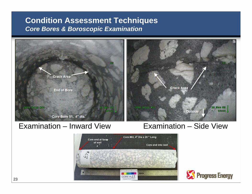
Examination – Inward View
Condition Assessment TechniquesCore Bores & Boroscopic Examination
Examination – Side View
23

1
2
3
6
5
4
Plan View
Buttress #(typical)
Construction Opening
24
SeawaterAuxiliary
Bldg
Turbine Bldg
Intermediate Bldg
Control Complex
Heater Bay Bldg
Fuel Transfer
Bldg
Fuel Pool
Aux Bldg EDG Bldg

R
T
V W X
AAZ
S
P
M O
LKJ
FED
G IH
Pour 3
Pour 4
Pour 5
Pour 6
Pour 7
Pour 8
Pour 9
Pour 10
Pour 11
Pour 12
Pour 13
Pour 14
Pour 15
Pour 16
Pour 1
Pour 2
- - - - - - - - - - - EL 240’
- - - - - - - - - - - EL 250’
- - - - - - - - - - - EL 230’
- - - - - - - - - - - EL 220’
- - - - - - - - - - - EL 210’
- - - - - - - - - - - EL 200’
- - - - - - - - - - - EL 190’
- - - - - - - - - - - EL 180’
- - - - - - - - - - - EL 170’
- - - - - - - - - - - EL 160’
- - - - - - - - - - - EL 150’
- - - - - - - - - - - EL 140’
- - - - - - - - - - - EL 130’
- - - - - - - - - - - EL 120’
- - - - - - - - - - - EL 110’
- - - - - - - - - - - EL 100’
- - - - - - - - - - - EL 90’CL CL CL CL
Containment “Unfolded” – Buttress 2 to 5Mosaic IR Overlay scale is approximate
12
3
6
54
CL
Aux Bldg Roof EL 167’ 8”
Intermediate Bldg Roof EL 149’ 0”
SGR
Opening
Equipment Hatch
A B C
D F
G I
E
H
J K L
M O
P R
N
Q
S T U
V X
Y AA
W
Z
AB ADAC
A B C A B C
D F
G I
E
H
J K L
M O
P R
N
Q
S T U
V XW
Y
Z
AA
AB
25
AC
AE
AF
AG
SGR
Opening
Y
10’ x 60’ 13’ x 42’ 10’x 16’
IR scans completed
per PT-407T:
Blue = no delamination
Actual IR scan output
data:
Blue = no delamination
Yellow= transition
Red = delaminated
Drawing scale is not exact
EL 128’
EL 128’8’ x 15’
20’ x 22’10’ x 25’
6’ x 40’ @
EL 164’’
EL 150’’
14’
x
10’
14’
x
6’
Conclusion – IR scans with confirmation core bores identified delamination only in the Buttress 3-4 span above the Equipment Hatch, as shown in red aboveConclusion – IR scans with confirmation core bores identified delamination only in the Buttress 3-4 span above the Equipment Hatch, as shown in red above
Buttress # 3 Buttress # 4 Buttress # 5Buttress # 2

10’ x60’
Pour 3
Pour 4
Pour 5
Pour 6
Pour 7
Pour 8
Pour 9
Pour 10
Pour 11
Pour 12
Pour 13
Pour 14
Pour 15
Pour 16
Pour 1
Pour 2
- - - - - - - - - - - EL 240’
- - - - - - - - - - - EL 250’
- - - - - - - - - - - EL 230’
- - - - - - - - - - - EL 220’
- - - - - - - - - - - EL 210’
- - - - - - - - - - - EL 200’
- - - - - - - - - - - EL 190’
- - - - - - - - - - - EL 180’
- - - - - - - - - - - EL 170’
- - - - - - - - - - - EL 160’
- - - - - - - - - - - EL 150’
- - - - - - - - - - - EL 140’
- - - - - - - - - - - EL 130’
- - - - - - - - - - - EL 120’
- - - - - - - - - - - EL 110’
- - - - - - - - - - - EL 100’
- - - - - - - - - - - EL 90’CL CL CL CL
Containment “Unfolded” – Buttress 5 to 2
Intermediate Bldg Roof
EL 149’ 0”
Fuel Transfer Bldg Roof
EL 200’ 4”
Intermediate Bldg Roof
EL 149’ 0”
B C
D F
G I
E
H
J K L
M ON
A B C
D F
G I
E
H
J K L
M ON
A B C
D F
G I
E
H
J K L
M ON
P RQ
S T U
V X
Y AA
W
Z
AB ADAC
P RQ
S T U
V X
Y AA
W
Z
AB ADAC
26
12
3
6
54
CL
Q
R
P
8’ x 16’
9’ x 12’
EL 160’
EL 143’
EL 119’
8’ x 12’
Actual IR scan output
data:
Blue = no delamination
Yellow= transition
Red = delaminated
28’ x11’
EL 122’
6’ x 15’ 6’ x 24’3’ x 9’
EL 180’
Conclusion – No delamination identified in these Buttress spansConclusion – No delamination identified in these Buttress spans
Drawing scale is not exact
IR scans completed
per PT-407T:
Blue = no delamination
Buttress # 6 Buttress # 1 Buttress # 2Buttress # 5

Core Bores Buttress Spans 2 - 3 - 4 - 5 (as of February 5, 2010)
Buttress # 3 Buttress # 4 Buttress # 5Buttress # 2
27
12
3
6
54
CL
Conclusion – Delamination is confined between Buttresses 3-4 spanConclusion – Delamination is confined between Buttresses 3-4 span
Drawing scale is not exact

Buttress # 6 Buttress # 1 Buttress # 2Buttress # 5
Core Bores Buttress Spans 5 - 6 - 1 - 2 (as of February 5, 2010)
28
12
3
6
54
CL
Conclusion – Core bore hole(s) boroscopic exams on these Buttress spans confirm the IR results, that no delamination has occurredConclusion – Core bore hole(s) boroscopic exams on these Buttress spans confirm the IR results, that no delamination has occurred
Drawing scale is not exact

Core Borings
29
Conclusion – Delamination has only been observed in core bore hole(s) boroscopic exams in the buttress 3-4 span, as accurately predicted by IR
Conclusion – Delamination has only been observed in core bore hole(s) boroscopic exams in the buttress 3-4 span, as accurately predicted by IR

Buttress # 3 Buttress # 4
Equipment Hatch area(tendons continue below)
Buttress(typical)
Tendon Pattern
CL CL
Removed Tendon
Energized Tendon
Tendon Pattern at time of cutting SGR Opening
30
SGR Opening

OPERATIONAL EXPERIENCE (OE)
31

• Worley Parsons• 1976 dome delamination investigation and repair (as Gilbert /
Commonwealth)
• Structural Preservation Systems (SPS)• Largest Concrete Repair Contractor in the US, 2nd largest Concrete
Contractor (of any type) in the US• Defects, Damage, and Deterioration
• Performs > 4,000 repair projects per year
• Wiss, Janney, Elstner, Inc (WJE)• Structural engineering and materials science firm specializing in
failure investigations and problem solving• Specialist in structural condition assessments and design of repairs
and retro-fits for reinforced and post tension concrete structures• Conducted original CR3 Structural Integrity Test (SIT)
Concrete OE
32

ROOT CAUSE ANALYSIS
33
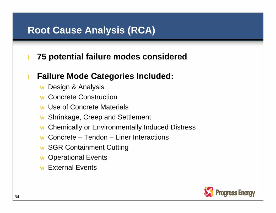
l 75 potential failure modes considered
l Failure Mode Categories Included:w Design & Analysisw Concrete Constructionw Use of Concrete Materialsw Shrinkage, Creep and Settlementw Chemically or Environmentally Induced Distressw Concrete – Tendon – Liner Interactionsw SGR Containment Cuttingw Operational Eventsw External Events
Root Cause Analysis (RCA)
34

• Impulse Response (IR) Scans • Boroscopic Inspections
• Core bore holes
• Inside the delaminated gap
• Visual Inspections • Delamination at SGR Opening
• Larger fragments from concrete removal process
• Containment external surface
Root Cause AnalysisField Data Acquisition
35
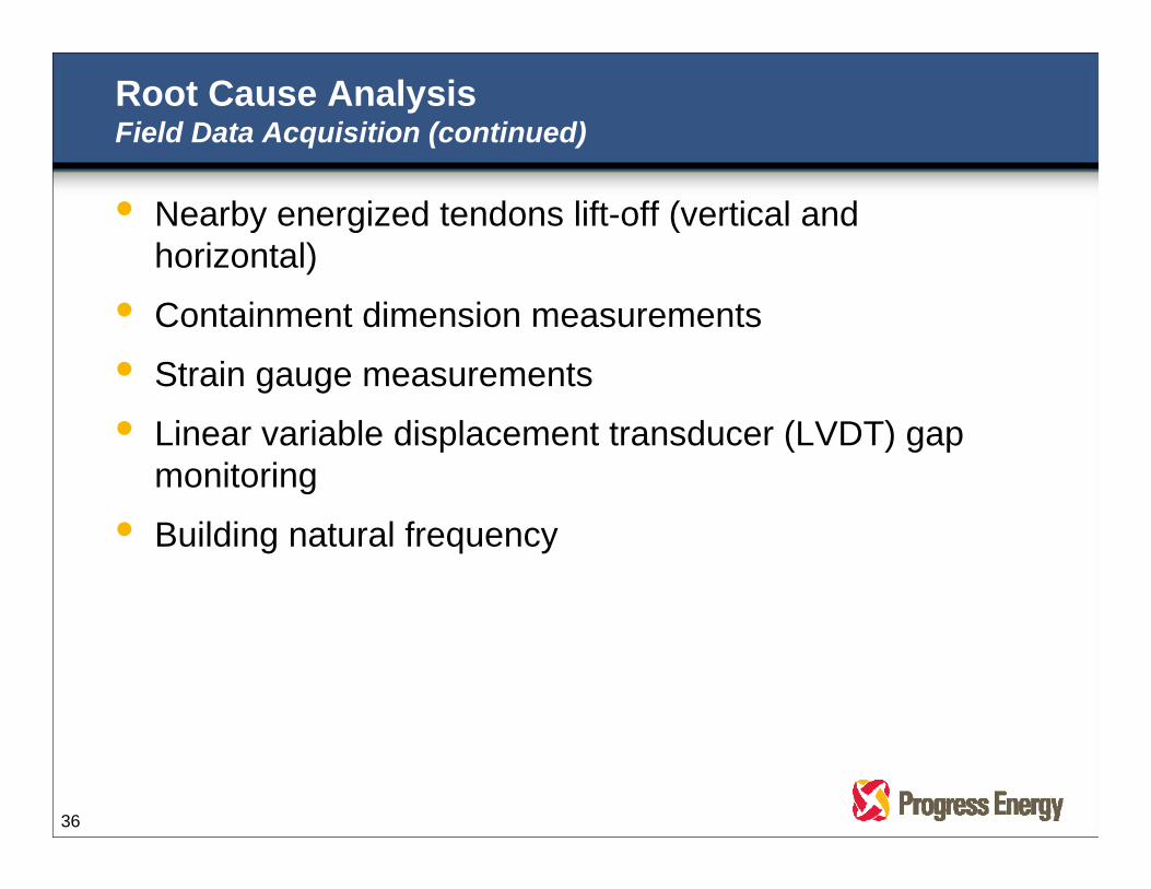
• Nearby energized tendons lift-off (vertical and horizontal)
• Containment dimension measurements
• Strain gauge measurements
• Linear variable displacement transducer (LVDT) gap monitoring
• Building natural frequency
Root Cause AnalysisField Data Acquisition (continued)
36
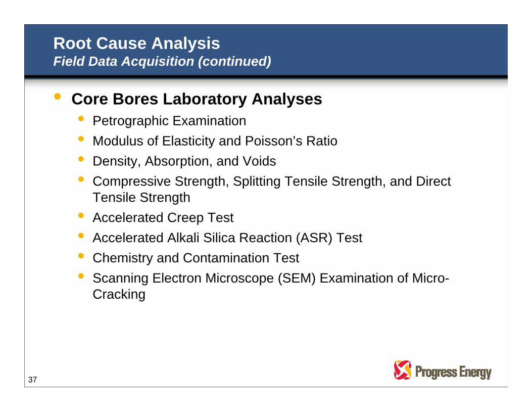
• Core Bores Laboratory Analyses • Petrographic Examination• Modulus of Elasticity and Poisson’s Ratio• Density, Absorption, and Voids• Compressive Strength, Splitting Tensile Strength, and Direct
Tensile Strength• Accelerated Creep Test• Accelerated Alkali Silica Reaction (ASR) Test• Chemistry and Contamination Test• Scanning Electron Microscope (SEM) Examination of Micro-
Cracking
Root Cause AnalysisField Data Acquisition (continued)
37

l 65 Failure Modes Refuted
l Remaining 10 Failure Modes were Combined for Root Cause Analysis (with 3D Fracture Analysis and Various Special Tests) to Determine their Significance (if any)
l Delamination Occurred as a Result of Outage Activities to Create an Opening for Steam Generator Replacement
Root Cause Analysis
38
Yellow line denotes boundary of delamination

DESIGN BASIS ANALYSIS
39

MPR Design Basis AnalysisFinite Element Analysis (FEA) Model Details
Mesh at Ring Girder connection
Mesh at Foundation connection
Modeling of Tendons
Composite FEA Model
40

REPAIR SEQUENCE
41

Engineering & Repair Work Flow
De-tension Additional Tendons
ImplementCrack Arrest
Strategy
Delamination Removal
Re-tensioning & Post-Repair
Testing
EC ModPhase 1
Crack ArrestEC 75000
EC ModPhase 3RemovalEC 75219
RCA Failure Modes Analysis
Cross CheckFinal Root
Cause Analysis
MPR 3D Finite Element
Analysis
EC ModPhase 2
De-tensioningEC 75218
RCA Failure Modes Analysis
Cross Check
EC ModPhase 4
PlacementEC 75220
EC ModPhase 5
Re-TensioningEC 75221
Reinforcement & Concrete Placement
SGT Engineering & Construction Input (Permanent Repair)
MPR TendonAnalysis
Sequence
Permanent Repair
SGT Engineering & Construction Input
(Repair Preparations)
PII AbaqusAnalysis of
MPR Tendon (# and sequence)
Indicates Completed Task
42
MPR Calcon Tendon
(# and sequence)

Summary & Questions
43
l Design is Acceptable for Normal and Emergency Operations
l Construction was in Accordance with Design
l Delamination Occurred during the Outage
l Investigation was Thorough and Comprehensive
l New State-of-the-Art Analytical Methods Had to be Created to Analyze Containment Response