crypto-lock - moniteqm… · model cc-8521an crypto lock single door access control system...
TRANSCRIPT

CRYPTO-LOCK
Model CC-8521AN Single Door Access
Control System (2/20)
MONITEQ, Inc.

2

3
Crypto-Lock Model CC-8521AN
INSTRUCTION MANUAL
TABLE OF CONTENTS 1. INTRODUCTION ....................................................................................................42. SPECIFICATIONS...................................................................................................63. SUPPLIED EQUIPMENT........................................................................................74. FUNCTIONS OF CONTROLS AND INDICATORS.............................................8
A. KEYPAD ............................................................................................................8 B. LOGIC BOARD..................................................................................................8 C. POWER SUPPLY BOARD ................................................................................8
5. INSTALLATION AND SETUP...............................................................................9A. INSTALLATION................................................................................................9B. SETUP.................................................................................................................9
6. OPERATING PROCEDURE ................................................................................127. THEORY OF OPERATION..................................................................................13
A. GENERAL.........................................................................................................13B. KEYPAD...........................................................................................................13C. LOGIC BOARD................................................................................................13D. POWER SUPPLY BOARD..............................................................................13

4
1. INTRODUCTION
Figure 1, CC-8521AN Crypto-Lock
The Crypto-Lock Model CC-8521AN is a versatile, easily installed and operated single door access control system. It provides reliable keypad access control using a single 3, 4 or 5-digit PIN code for all users.
The system, pictured in Figure 1, includes a built-in 12Vdc and 24Vdc, 2A power supply to power electric strikes and magnetic locks, eliminating the need for a separate power supply unit. It provides the high in-rush currents required to reliably open heavy duty locking devices such as Von Duprin* rim latch retraction units and Sargent & Greenleaf Brute* electric locks. A unique, switch selectable current limiter safely achieves continuous activation of large solenoid-operated locks. This feature limits the current to a value that will reliably hold the lock open without damaging its solenoid.
The power supply includes a battery charger and monitoring circuit that automatically maintains optional batteries. Regulator Q3 provides 13.5Vdc at up to 2A to relay K1 when the OUTPUT SOURCE switch is set to INT 12V.
The length of time that the lock remains released after entry of the valid PIN is adjustable from 3 to 60 seconds. An invalid PIN penalty feature provides for ignoring all keypad entries for from 3 to 60 seconds after an invalid digit is entered. This greatly reduces the possibility of gaining access by guessing PIN codes, and is particularly effective when shorter PIN lengths are used.
The stainless steel keypad includes a green LED that illuminates when the lock is released.
A visitor button on the keypad activates an annunciator in the control unit and also generates an output voltage for an external device.
Installation and set-up are readily accomplished using the wiring diagram affixed inside the enclosure door and also contained in this manual. Slide switches set the PIN length (3, 4 or 5 digits), output voltage (12 or 24 Vdc), and enable or disable holding current limiting. Five 10-position DIP switches are used to set the PIN. The open duration time and penalty time are set using analog control knobs.
The CC-8521AN can be wired to operate on either 115 or 230 Vac, 50 or 60 Hz. It is wired at the factory for 115 Vac.
A typical installation of the CC-8521AN is illustrated in Figure 2.
*Von Duprin is a registered trademark of the Ingersoll-Rand Company; Brute is a registered trademark of Sargent & Greenleaf, Inc.

5
CC-8521ANCRYPTO
-LOCK
Versatile outputs:* Fail safe or fail secure* 12 or 24Vdc @ 2A continuous* High-rush current opens largest locks* Holding current can be limited to 300mA
115/230 Vac,50/60Hz
Magnetic lock(fail-safe)
Electric lock or strike (fail-secure)
ExternalAnnunciator
Output
Low BatteryWarning Output
KEYPAD WITH STATUS LED AND VISITOR
BUTTON
Figure 2, Typical Installation of the Crypto Lock
Available settings:* Number of PIN digits (3, 4 or 5)* PIN number* Open duration (3 to 60 sec.)* Penalty duration (3 to 60 sec.)* Output (12 or 24 Vdc)* Limit holding current to 300mA
RELEASEBUTTON

6
2. SPECIFICATIONS
Power required 115/230 Vac, 50 or 60 Hz, 60 W Output 12Vdc, 0.8A or 24 Vdc, 2A continuous Holding current Can be limited to 300mA (switch selectable) In-rush current capacity 16A Relay contacts 10A, SPDT (Form C) Battery backup 12Vdc or 24Vdc, automatic transfer and charging
(batteries optional) Battery monitoring Warning lamp, beeper and output signal activate when
battery is low PIN code length 3, 4 or 5 digits, switch selectable Open duration Adjustable, 3 to 60 seconds Penalty function Invalid digits temporarily disable operation Penalty time Adjustable, 3 to 60 seconds Remote release Dry contact closure input Keypad cable
Keypad 14-conductor, #22
Annunciator 2-conductor, #22 Supplied cable 20 ft., 14-cond., #22 Maximum length 200 ft.
Enclosure 19 gauge steel, powder painted, gray, knockouts for conduit, and cam lock (included), holes to accommodate padlock (not included)
Dimensions 12H x 9W x 4.5D in. Option available: CC-BATT, 12Vdc, 7AH rechargeable battery (two
required) *enclousure does not accomodate
Narrative description: Model CC-8521AN Crypto Lock single door access control system including control unit, weather-proof 10-button keypad in stainless steel spy-proof housing with visitor button and 20 ft. water-blocking cable, user code cannot be re-programmed, changed or revealed in any way from keypad. Includes a penalty time adjustment (3-60 sec.), open time adjustment (3-60 sec.), code length switch (3, 4 or 5 digits), five 10- position DIP switches to set the PIN code, output voltage switch (12 or 24 Vdc, 2A continuous, 16A in-rush current), holding current limit switch (2A or 300mA, fail-safe and fail-secure lock outputs, external annunciator output, release input, and low-battery, penalty, and power warning lamps. The metal enclosure includes a cam lock and has provisions for a padlock. Input power is 115/230 Vac, 50/60Hz.
10 button
7
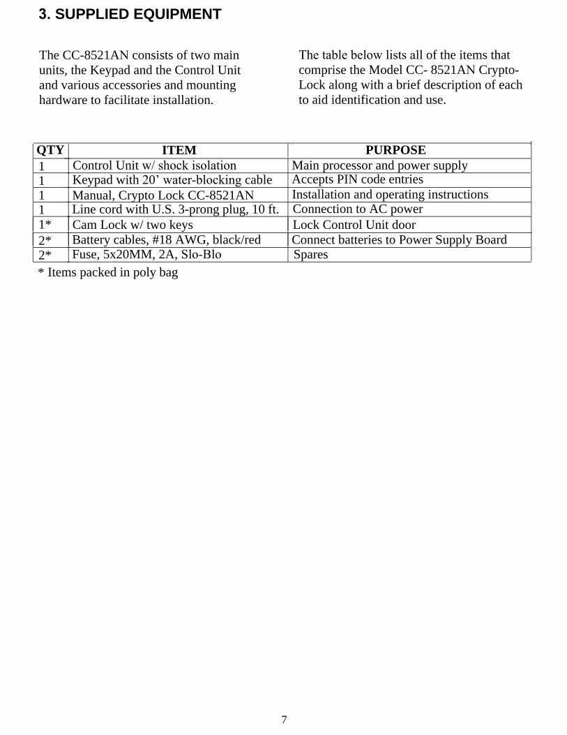
3. SUPPLIED EQUIPMENT
The CC-8521AN consists of two main units, the Keypad and the Control Unit and various accessories and mounting hardware to facilitate installation.
The table below lists all of the items that comprise the Model CC- 8521AN Crypto-Lock along with a brief description of each to aid identification and use.
QTY ITEM PURPOSE 1 Control Unit w/ shock isolation Main processor and power supply
1 Keypad with 20’ water-blocking cable Accepts PIN code entries
1 Manual, Crypto Lock CC-8521AN Installation and operating instructions
1 Line cord with U.S. 3-prong plug, 10 ft. Connection to AC power 1* Cam Lock w/ two keys Lock Control Unit door 2* Battery cables, #18 AWG, black/red Connect batteries to Power Supply Board 2* Fuse, 5x20MM, 2A, Slo-Blo Spares
* Items packed in poly bag

8
4. FUNCTIONS OF CONTROLS AND INDICATORS
A. KEYPADKeys 1 through 0 are used to enter thePIN code. Keys * and # are not used.Green LED indicator - Illuminates whenthe correct PIN code has been enteredand the door is released.Annunciator Button - Pressing sounds anannunciator in the control unit and alsoactivates a 12 Vdc signal for use with anexternal device.
B. LOGIC BOARDPIN Code DIGIT Select Switches - Usedto set the PIN code. One number on eachswitch is selected corresponding todigit-1 through digit-5 of the PIN code.To select a number, slide thecorresponding switch to the ON position.If the PIN code is less than 5 digits, theslide switches for the unused digits canbe left in the OFF position.
DURATION Control - Determines how long the door relay will remain energized after the correct PIN code is entered or the Release Button is pressed. The range is adjustable from approximately 3 to 60 seconds.
PENALTY Control - The penalty feature is designed to temporarily disable the system when an invalid digit is entered on the Keypad. The range is adjustable from approximately 3 to 60 seconds.
PENALTY Lamp - Illuminates when the penalty feature is activated.
# OF DIGITS Switch - Selects either 3, 4, or 5 digits for the length of the PIN code.
POWER Indicator LED - Indicates that the Logic Board is powered.
C. POWER SUPPLY BOARDOUTPUT VOLTAGE SOURCE (INT24V, EXT, or INT 12V) - Selects thevoltage that will operate the lockingdevice attached to the system. Alwaysremove power (AC and batteries) beforeresetting this switch. In the INT 24V andINT 12V positions the internal powersupply provides either 24VDC or 12VDCrespectively to the locking device. In theEXT position the external voltage appliedto pin 12 of T1 on the Power SupplyBoard is applied through the relay to thelocking device.
OUTPUT MODE (DIRECT or LIMIT HOLDING CURRENT) - In the DIRECT position provides up to 2A of continuous holding current. In the LIMIT HOLDING CURRENT position the holding current is limited to approximately 300 mA after the locking device is initially energized. This setting permits holding an electric lock or strikes open without damaging its solenoid. Note: Current limiting operates only when the OUTPUT VOLTAGE SOURCE Switch is set to INT 24V.
L1 Indicator LED - Indicates that the Power Supply Board is powered.
L2 Indicator LED - Flashes approximately every 15 seconds when the battery is low.
B1 Beeper - Sounds approximately every 15 seconds when the battery is low.
F1 and F2 - AC low voltage, 2A Slo-Blo F3 - Batteries, 2A Slo-Blo F4 - Lock current, 2A Slo-BloF5 - AC Primary Voltage, 2A Slo-Blo

9
5. INSTALLATION AND SETUP
Installation of the CC-8551AN Crypto Lock consists of mounting the Keypad and Control Unit, connecting the Keypad cable, power cord, external lock and other devices and installing the batteries (optional). Setup includes setting switches to determine the lock voltage and current limits and setting the PIN code length and digits.
A. INSTALLATION1) Mount the Keypad approximately 36 to44 inches above the floor on the unsecuredside of the door.
2) Mount the electric lock, strike or magnetaccording to the manufacturer'sinstructions.
3) Mount the Control Unit on the secureside of door in an area convenient to thedoor and an electrical outlet.
4) If required, install the supplied CamLock in the knockout hole provided for thatpurpose on the enclosure door.Alternatively, if a padlock (not supplied) isto be used remove the two 3/8" nylon plugsfrom the padlock holes. The padlock'sshackle must be first inserted through thehole on the side of the enclosure, then thedoor can be closed so that the padlock holeon the door also passes over the shackle. Ifthe door does not need to be locked, twoscrews can be used in the door edge holesto hold it closed.
5) Connect the Keypad to the Control Unitby number as shown in Figure 3. Twentyfeet of cable is supplied with the Keypad.The Keypad can be located up to 200 feetfrom Control Unit using additional cable.(Requires 14 conductors, #22).
6) Connect the electric lock, strike ormagnet as shown in Figure 3.
7) May connect a Release Button(not supplied), and external 12VDCannunciator (not supplied), as shown inFigure 3. Note that an internal annunciatoron the Logic Board will sound when theKeypad's annunciator button is pressed.
8) Install and connect the optional batteriesas shown in Figure 3 using the twosupplied battery cables. Use only 12V, 1.2to 7AH rechargeable sealed lead acidbatteries.
9) Connect the AC Power Cord toTerminal T4 in accordance with theavailable voltage (115 or 230Vac) asshown in Figure 3.
10) Connect the transformer primarywires to Terminal T3 in accordance withthe available voltage (115 or 230 Vac) asshown in Figure 3. CAUTION! TheControl Unit is shipped from the factorywired for 115 Vac operation. Refer toFigure 3.

10
3) Set the # OF DIGITS switch to thedesired number of PIN digits (3, 4 or 5) .
4) Set the valid PIN code using the DIGITDIP switches. DIP switches for unuseddigits can all be set to OFF.
5) Set the DURATION control to theapproximate desired open time. (Min.=3sec., Max.=60 sec.)
6) Set the PENALTY control to theapproximate desired PENALTY time(Min.=3 sec., Max.=60 sec.)
7) Connect the power cord to anappropriate source of AC power and verifythat the POWER indicators illuminate.
8) Enter the valid PIN code on the keypadand verify that the lock releases and thatthe green LED on the Keypad illuminates.
2) Set the OUTPUT MODE switch toLIMIT HOLDING CURRENT for usewith the Sargent Greenleaf Brute lock orother devices that can be damaged byholding currents in excess of 300 mA.For other locks and magnetic releasesselect the DIRECT position.
B. SETUP1) Set the OUTPUT source switch inaccordance with the voltage rating of thelock being used (12 or 24 Vdc).

11
MONITEQ , Inc.Tel: 1-800-989-9891 Model CC-8521ANDigi ta l Access Control wi th Heavy Duty Lock Driver
T3 1 2 3
115 Vac
BRN WHT
GRN RED
N/C
230 Vac
BRN GRN WHT
RED
(PC B “ G9844, 94V-01 ”)
(PCB Rev C)
Low Battery Warnings -The “LOW BATT” indicator will light and a beep will sound every 15 seconds when the battery charge level is low.
Figure 3, Crypto Lock Wiring Diagram
POWER SUPPLY BOARD
LOGIC BOARD

12
6. OPERATING PROCEDURE
To operate the CC-8521AN, enter the valid 3, 4, or 5 digit PIN code on the keypad. When the valid PIN code is entered, the green LED on the Keypad will illuminate and the door will release.
The CC-8521AN Keypad has a built-in annunciator button. Pressing this button causes an annunciator to sound in the Control Unit. If an external annunciator is connected as shown in Figure 3 it will also sound when this button is pressed.
If one or more incorrect PIN code digits are entered the system will enter a penalty mode and will not recognize any digits for the time period set by the PENALTY control on the Logic Board in the Control Unit. After the penalty time has elapsed the unit will return to normal operation and entering the valid PIN code on the Keypad will release the door.
If the external Release Button has been installed it can be used by an attendant to release the lock from the secure side of the door.

13
7. THEORY OF OPERATION
A. GENERALThe CC-8521AN Crypto Lock consistsof two main units, the Keypad andControl Unit.
B. KEYPADRefer to the Keypad Schematic Diagramon moniteq.com. The Keypad contains atelephone-type key switch, an LEDindicator lamp and an annunciator pushbutton.
The Control Unit contains the Logic Board, the Power Supply Board and the Power Transformer.
C. LOGIC BOARDThe Logic Board processes key strokesfrom the Keypad to determine if the lockrelay should be energized based on thePIN code set on the DIGIT DIP switches.The Logic Board also accepts the inputfrom the Annunciator Button on theKeypad for routing to the Power SupplyBoard, and generates a signal to illuminatethe green LED on the Keypad when a validPIN code has been entered.Chip U4 is a divide-by-8 counter thatdecodes successive inputs from theKeypad. The decoded outputs of U4 arecoupled through the respective DIGIT DIPswitches (S1,2,3,5 and 7) to U4's ClockEnable input. If a valid first digit ispressed the high signal on the "0" decodedoutput (U4, pin 2) is coupled through thevalid number's key switch through T1 pin11, U2C and Q4 to the clock enable inputof U4, advancing the counter one countand causing the "1" decoded output (U4,
pin 1) to go high. If the second digit from the keypad is also valid the process repeats, again advancing the counter. When the last correct digit is entered a high signal is coupled to both inputs of gate U2:B that then triggers the Open Timer, U1:B. The output of U1:B then remains high for a time period set by the DURATION potentiometer R19. This output is coupled to Relay Driver Q5 which grounds the signal connected to the door control relay on the Power Supply Board.
If an incorrect digit is entered on the Keypad the divide-by-8 counter U3 is advanced one count, thereby triggering Penalty Timer U1:A that resets Open Timer U1:B for a time period set by PENALTY potentiometer R8.
D. POWER SUPPLY BOARDThe Power Supply Board contains the powersupplies for powering both the internalcircuits and driving the external lockingdevice. It also manages the standby batteriesand routes signals from the external releasebutton to the Logic Board and from theLogic Board to the external annunciator.The 24Vac output from the secondary of thepower transformer is applied to bridgerectifier D2 and filter components C4, R3and C2 and regulator Q2 to generate27.3Vdc. When OUTPUT SOURCE switchS2 is set to INT 24V and OUTPUT MODEswitch S1 is closed, this voltage is coupledthrough door control relay K1 to either pin10 or pin 11 of T2 depending on the status

14
Regulator Q4 provides operating voltage for circuits on both the Power Supply Board and through T1, pin 4, to the Logic Board.
Regulator Q5 provides operating voltage for the battery monitoring circuits of U1 and U2. U1:A compares the battery voltage (T2, pin 6) with a reference voltage to determine the battery charge level. When the level falls below that of the reference the output of U1: A trigger timer U2, causing L2 to flash and beeper B1 to sound approximately every 30 seconds.
The annunciator control signal from the Logic Board enters through T1, pin 6 and is coupled directly to the external annunciator through T2, pin 16.
Terminals T3 and T4 are provided to allow wiring the power transformer primary winding for either 115VAC or 230VAC. Refer to Figure 3 for correct wiring of T3 and T4.
of K1. Capacitor C3 provides additional "in-rush" current immediately after K1 closes to assure activation of the solenoids in larger, heavy-duty electric locks. K1 is controlled by an input from the Logic Board on T1, pin 2 (RELAY-). When OUTPUT MODE switch S1 is in the LIMIT HOLDING CURRENT position the output current is limited to approximately 300mA after capacitor C3 discharges. This serves to prevent overheating and possible damage to solenoid-operated locks that otherwise could not be maintained open for long periods of time.
Regulator Q3 provides 13.5Vdc at up to 2A to relay K1 when the OUTPUT SOURCE switch is set to INT 12V.

15

One Year Limited Warranty
MONITEQ, INC. products are warranted to be free from factory defects for a period of one year from the date of shipment. The repair or replacement of a defective part shall be at the option of the factory when the product is shipped prepaid and insured by the owner. This warranty is void in cases of abuse, misuse, mishandling, modification, or repair by unauthorized persons. This warranty is given in lieu of all other warranties expressed or implied. MONITEQ, INC. is not liable for incidental or consequential damages resulting from the operation or failure of this product. This warranty recognizes any and all rights you may have under appropriate state law.
MONITEQ, Inc.
MONITEQ, INC. 213 Church Street Greensboro , MD 21639
Tel: 1-410-827-8870 1-800-989-9891
Fax: 1-410-827-8875 E-mail: [email protected]: www.moniteq.com
16