cruise control system article text - lil evo colt summit mirage s .pdf... · cruise control system...
TRANSCRIPT

CRUISE CONTROL SYSTEMArticle Text
1992 Mitsubishi MirageFor a a a a a
Copyright © 1998 Mitchell Repair Information Company, LLCMonday, April 01, 2002 09:56AM
ARTICLE BEGINNING
1991-92 ACCESSORIES & SAFETY EQUIPMENT Chrysler Motors/Eagle/Mitsubishi Cruise Control Systems
Dodge; Colt, Colt 200, Stealth Eagle; Summit Mitsubishi: Eclipse, Mirage, 3000Gt Plymouth; Colt, Colt 200
DESCRIPTION & OPERATION
The cruise control system is electronically controlled andvacuum actuated. System components include a control unit, vacuumpump, actuator, cruise control switch, clutch pedal switch,accelerator pedal switch, cruise indicator light, diode (if equipped),inhibitor switch (A/T), idle switch, overdrive switch, stoplightswitch, throttle position sensor, vehicle speed sensor and A/T controlunit. The system also has self-diagnostic capability. When self-diagnostic mode is activated, each switch and sensor is checked fordefects. If cruise control system has been canceled without using anormal cancel method, a code will be set and stored in control unit.Codes can be retrieved to help determine which circuit ismalfunctioning.
ADJUSTMENTS
CRUISE CONTROL CABLE
Colt, Colt 200, Eclipse, Mirage & Summit 1) Warm engine to normal operating temperature. On allmodels, except Eclipse, remove air cleaner. On all models, removecable protector. Ensure cable is free of bends and folds. Turnignition on for 15 seconds. Loosen lock nut "C". See Fig. 1, 2 or 3. 2) With the end of linkage "C" held in contact with stopperon linkage "B", adjust play in cruise control cable (inner cable) to .04-.08 (1-2 mm). Tighten lock nut.
Fig. 1: Adjusting Cruise Control Cable (Colt, Colt 200, Mirage &Summit)

CRUISE CONTROL SYSTEMArticle Text (p. 2)
1992 Mitsubishi MirageFor a a a a a
Copyright © 1998 Mitchell Repair Information Company, LLCMonday, April 01, 2002 09:56AM
Courtesy of Mitsubishi Motor Co.
Fig. 2: Adjusting Cruise Control Cable (Eclipse)Courtesy of Mitsubishi Motor Co.
Fig. 3: Adjusting Cruise Control Cable (Stealth & 3000GT)Courtesy of Mitsubishi Motor Co.
Stealth & 3000GT 1) Warm engine to normal operating temperature. Ensure cableis free of bends and folds. Remove cable protector. Loosen adjustingand lock nuts of link "A". Turn ignition on. See Fig. 1, 2 or 3. 2) Turn adjusting nut "A" to reduce free play of inner cableof cruise control cable. When lever of link "A" contacts intermediatelink "B", back off adjusting nut one turn. 3) Free play of inner cable should be .04-.08 (1-2 mm).Tighten lock nut. Ensure end of fixed Speed Adjusting Screw (SAS) isin contact with stopper of throttle lever.
TROUBLE SHOOTING

CRUISE CONTROL SYSTEMArticle Text (p. 3)
1992 Mitsubishi MirageFor a a a a a
Copyright © 1998 Mitchell Repair Information Company, LLCMonday, April 01, 2002 09:56AM
INSPECTION
Before performing TROUBLE SHOOTING steps, inspect vacuumpump, linkage assembly, actuator, cables and vacuum hoses. Ensurelinkage and cables move smoothly. Ensure cables do not have excessiveslack or tension.
NOTE: For further trouble shooting information, see CHECK RESULTS & SYMPTOM CHARTS. See Figs. 9-17.
SYSTEM CANCELS OR WILL NOT RESET AFTER CANCELLATION
1) Check trouble codes, see SELF-DIAGNOSTICS under DIAGNOSIS& TESTING. If no trouble codes are stored, check to see if cruisecontrol can be set. 2) If cruise control can be set, system may have beencanceled because of driving on steep hills or loose wiring connection.If cruise control still cannot be set, perform SYSTEM INPUT TESTSunder TESTING.
NOTE: If vacuum pump circuit and parts of actuator check okay, replace control unit.
3) If SYSTEM INPUT TESTS check okay, check vacuum pump. SeeTEST NO. 6 under CIRCUIT TESTS (EXCEPT ECLIPSE). If system input testsdo not check okay, see INPUT CODE CHART. See Fig. 7.
TESTING
CRUISE CONTROL SWITCH FUNCTION TEST
NOTE: If vehicle speed decreases approximately 9 MPH below set speed, set speed will be canceled.
Colt, Colt 200, Eclipse, Mirage & Summit 1) Cruise control switch is part of multifunction switchmounted on steering column. To operate cruise control system, turnignition on. Turn cruise control switch to ON position. Ensureindicator light inside switch comes on.
NOTE: Speed will not set beyond system limit of 90 MPH.
2) With cruise control switch in ON position, drive vehicle25-90 MPH. Press and release SET button. Vehicle speed should stay atset speed. Instrument cluster cruise indicator light should come on.To increase set speed, turn control switch to RESUME position and holduntil new set speed is reached. 3) To lower set speed, press SET button and hold until newset speed is reached. To return to set speed after cancellation, moveRESUME switch from ON to OFF position. Vehicle speed should return toprevious setting before cancellation. Set speed should cancel when any

CRUISE CONTROL SYSTEMArticle Text (p. 4)
1992 Mitsubishi MirageFor a a a a a
Copyright © 1998 Mitchell Repair Information Company, LLCMonday, April 01, 2002 09:56AM
of the following occurs:
* Brake pedal is pressed. * Clutch pedal is pressed. * Transmission is shifted to Neutral or Park. * Cruise control main switch is turned off. * Ignition switch is turned off.
Stealth & 3000GT 1) Cruise control switch is mounted separately to steeringwheel. Turn main cruise control switch to ON position. Cruise controlindicator on instrument cluster should come on. 2) To operate cruise control system, turn ignition on. Drivevehicle at desired speed between 25 and 90 MPH. Move cruise controlswitch downward to set desired speed. Set indicator light should comeon. 3) Vehicle speed should stay at set speed. To increase setspeed, move control switch upward to RESUME position and hold untilnew set speed is reached. To lower set speed, move control switch downto COAST position. Hold until new set speed is reached. 4) To return to set speed after cancellation, move controlswitch upward to RESUME position. Vehicle speed should return toprevious setting before cancellation. Set speed should cancel when anyof the following occurs:
* Cruise control switch is pulled toward driver. * Brake pedal is pressed. * Clutch pedal is pressed. * Transmission is shifted to Neutral.
SELF-DIAGNOSTICS
1) Self-diagnostics should be performed when cruise controlcancels without driver using normal cancel modes. Self-diagnosticconnector is located on right side of fuse box. 2) On Eclipse and Mirage, use Multi-Use Tester (MB991341) oran analog voltmeter for code retrieval. Plug multi-use testerconnectors into cigar lighter and self-diagnostic connector. On Colt,Colt 200, Stealth, Summit and 3000GT, use analog voltmeter for coderetrieval. 3) On all models, if using voltmeter, connect leads of analogvoltmeter between cruise control terminal and ground terminal ofdiagnostic connector. See Fig. 4 or 5. Read voltmeter needle sweeps todetermine trouble code. See Fig. 6.
NOTE: On all models except Stealth & 3000GT, codes No. 15 and 16 will be displayed whether malfunction is present or not. On Stealth & 3000GT, a code 17 will not cause system to cancel.
4) Once trouble codes have been displayed, read TROUBLE CODECHART to find appropriate CIRCUIT TEST. See Fig. 6. See appropriateCIRCUIT TESTS. To clear trouble codes, disconnect positive battery

CRUISE CONTROL SYSTEMArticle Text (p. 5)
1992 Mitsubishi MirageFor a a a a a
Copyright © 1998 Mitchell Repair Information Company, LLCMonday, April 01, 2002 09:56AM
cable or go to next step. 5) Turn ignition on. Turn cruise control set switch on. Turncruise switch on and, in less than one second after cruise switch isturned on, turn resume switch on. 6) Press set switch and brake pedal simultaneously, holdingthem for more than 5 seconds. Ensure codes are cleared.
Fig. 4: Self-Diagnostic Connector Terminal ID (Exc. Stealth & 3000GT)Courtesy of Mitsubishi Motor Co.
Fig. 5: Self-Diagnostic Connector Terminal ID (Stealth & 3000GT)Courtesy of Mitsubishi Motor Co.

CRUISE CONTROL SYSTEMArticle Text (p. 6)
1992 Mitsubishi MirageFor a a a a a
Copyright © 1998 Mitchell Repair Information Company, LLCMonday, April 01, 2002 09:56AM
Fig. 6: Trouble Code ChartCourtesy of Mitsubishi Motor Co.
SYSTEM INPUT TESTS
1) System input tests should be performed if no trouble codesare stored when performing SELF-DIAGNOSTICS. 2) System input tests cycle each cruise control switch andsensor. On Eclipse, use Multi-Use Tester (MB991341) or an analogvoltmeter for system input check. 3) The multi-use tester setting is the same as setting forself-diagnostic. Plug multi-use tester connectors into cigar lighterand self-diagnostic connector. On Colt, Colt 200, Stealth, Summit and3000GT use analog voltmeter for system input check. 4) If using voltmeter, connect leads of analog voltmeterbetween cruise control terminal and ground terminal of diagnosticconnector. See Fig. 4 or 5. Turn ignition on. Turn cruise controlswitch to OFF position. Turn cruise control set switch to ON position. 5) Turn cruise control switch to ON position and within onesecond turn resume switch to ON position. On all models, perform eachswitch input test, following INPUT CODE CHART. See Fig. 7 or 8. 6) Cycle each switch until code is displayed. If code is notdisplayed, that switch or sensor is defective. When each switch orsensor is cycled and signals are reaching control unit, codes willcontinue to display. 7) When switch or sensor cycling stops, code display stops.If system input tests check okay, check vacuum pump. See TEST NO. 6under CIRCUIT TESTS (EXCEPT ECLIPSE).

CRUISE CONTROL SYSTEMArticle Text (p. 7)
1992 Mitsubishi MirageFor a a a a a
Copyright © 1998 Mitchell Repair Information Company, LLCMonday, April 01, 2002 09:56AM
Fig. 7: Input Code Chart (Except Stealth & 3000GT)Courtesy of Mitsubishi Motor Co.
Fig. 8: Input Code Chart (Stealth & 3000GT)Courtesy of Mitsubishi Motor Co.

CRUISE CONTROL SYSTEMArticle Text (p. 8)
1992 Mitsubishi MirageFor a a a a a
Copyright © 1998 Mitchell Repair Information Company, LLCMonday, April 01, 2002 09:56AM
Fig. 9: Check Results Chart (Colt, Colt 200, Mirage & Summit)Courtesy of Mitsubishi Motor Co.

CRUISE CONTROL SYSTEMArticle Text (p. 9)
1992 Mitsubishi MirageFor a a a a a
Copyright © 1998 Mitchell Repair Information Company, LLCMonday, April 01, 2002 09:56AM
Fig. 10: Symptom Chart (Colt, Colt 200, Mirage & Summit - 1 Of 2)Courtesy of Mitsubishi Motor Co.

CRUISE CONTROL SYSTEMArticle Text (p. 10)
1992 Mitsubishi MirageFor a a a a a
Copyright © 1998 Mitchell Repair Information Company, LLCMonday, April 01, 2002 09:56AM
Fig. 11: Symptom Chart (Colt, Colt 200, Mirage & Summit - 2 Of 2)Courtesy of Mitsubishi Motor Co.
CRUISE CONTROL SYSTEMArticle Text (p. 11)
1992 Mitsubishi MirageFor a a a a a
Copyright © 1998 Mitchell Repair Information Company, LLCMonday, April 01, 2002 09:56AM
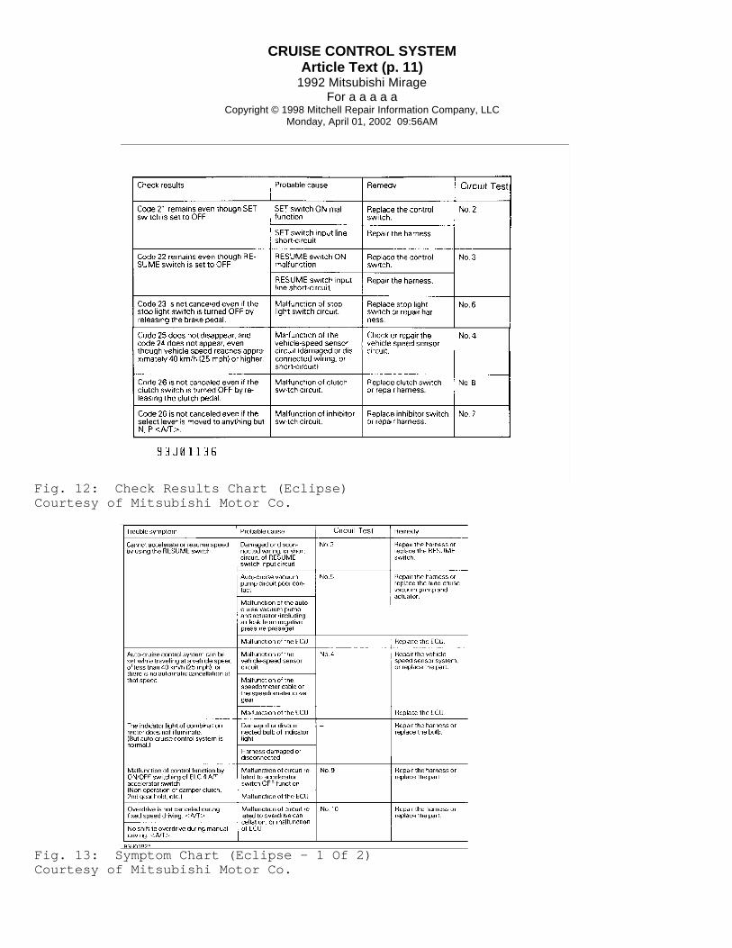
Fig. 12: Check Results Chart (Eclipse)Courtesy of Mitsubishi Motor Co.
Fig. 13: Symptom Chart (Eclipse - 1 Of 2)Courtesy of Mitsubishi Motor Co.

CRUISE CONTROL SYSTEMArticle Text (p. 12)
1992 Mitsubishi MirageFor a a a a a
Copyright © 1998 Mitchell Repair Information Company, LLCMonday, April 01, 2002 09:56AM
Fig. 14: Symptom Chart (Eclipse - 2 Of 2)Courtesy of Mitsubishi Motor Co.
CRUISE CONTROL SYSTEMArticle Text (p. 13)
1992 Mitsubishi MirageFor a a a a a
Copyright © 1998 Mitchell Repair Information Company, LLCMonday, April 01, 2002 09:56AM
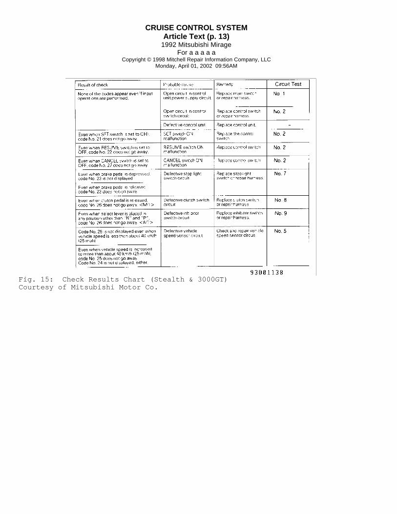
Fig. 15: Check Results Chart (Stealth & 3000GT)Courtesy of Mitsubishi Motor Co.

CRUISE CONTROL SYSTEMArticle Text (p. 14)
1992 Mitsubishi MirageFor a a a a a
Copyright © 1998 Mitchell Repair Information Company, LLCMonday, April 01, 2002 09:56AM
Fig. 16: Symptom Chart (Stealth & 3000GT - 1 Of 2)Courtesy of Mitsubishi Motor Co.

CRUISE CONTROL SYSTEMArticle Text (p. 15)
1992 Mitsubishi MirageFor a a a a a
Copyright © 1998 Mitchell Repair Information Company, LLCMonday, April 01, 2002 09:56AM
Fig. 17: Symptom Chart (Stealth & 3000GT - 2 Of 2)Courtesy of Mitsubishi Motor Co.
CIRCUIT TESTS (EXCEPT ECLIPSE)
NOTE: To identify circuit connector terminals, See Figs. 19-32. For wiring diagrams, See appropriate chassis wiring diagrams in this Section. For 1992 model wiring diagrams, See appropriate chassis wiring diagrams in the WIRING DIAGRAMS section.
Test No. 1 (Power Supply Circuit) 1) When cruise control switch is turned to ON position,battery voltage should be present on terminal No. 2 of control unit.

CRUISE CONTROL SYSTEMArticle Text (p. 16)
1992 Mitsubishi MirageFor a a a a a
Copyright © 1998 Mitchell Repair Information Company, LLCMonday, April 01, 2002 09:56AM
If voltage is not present, check fuse No. 2 and replace as necessary.If fuse is okay, replace switch or repair harness. 2) Control unit should be grounded at all times throughterminals No. 8 and 14. If circuit is not grounded, repair harness. OnColt, Colt 200, Mirage and Summit, control unit back-up power supplyshould have battery voltage at all times through terminal No. 16. Ifvoltage is not present, check fuse No. 8 and replace as necessary. Iffuse is okay, replace switch or repair harness.
Test No. 2 (Set & Coast Switch Ckt, Exc. Stealth & 3000GT) When set switch is turned to ON position, voltage should notbe present on terminal No. 17 of control unit. When set switch isturned to OFF position, battery voltage should be present on terminalNo. 17 of control unit. If circuit does not test correctly, replaceswitch or repair harness.
Test No. 2 (Set, Resume/Cancel Switch Ckt, Stealth & 3000GT) 1) When all switches are turned to OFF position, voltageshould not be present on terminal No. 18 of cruise control unit. Whenset switch is turned to ON position, 3 volts should be present onterminal No. 18 of control unit. 2) When resume switch is turned to ON position, 6 voltsshould be present on terminal No. 18 of control unit. When resumeswitch is turned to OFF position, voltage should be present onterminal No. 18 of control unit. 3) When cancel switch is turned to ON position, batteryvoltage should be present on terminal No. 18 of control unit. Whencancel switch is turned to OFF position, voltage should not be presenton terminal No. 18 of control unit. If circuit does not testcorrectly, replace switch or repair harness.
Test No. 3 (Resume Switch Circuit) When resume switch is turned to ON position, voltage shouldnot be present on terminal No. 18 of control unit. When resume switchis turned to OFF position, battery voltage should be present onterminal No. 18 of control unit. If circuit does not test correctly,replace switch or repair harness.
Test No. 4 (Indicator Light Circuit) When cruise control is active, battery voltage should bepresent on terminal No. 23 of control unit. When cruise control isturned to OFF position, voltage should not be present on terminal No.23 of control unit. If circuit does not test correctly, replace switchor repair harness.
Test No. 5 (Vehicle Speed Sensor Circuit) When vehicle moves slowly, voltage should alternate from zerovolts to 2 or more volts at terminal No. 19 of control unit. Ifcircuit does not test correctly, replace sensor or repair harness.
Test No. 6 (Vacuum Pump Circuit) 1) When release valve is on, battery voltage should not be

CRUISE CONTROL SYSTEMArticle Text (p. 17)
1992 Mitsubishi MirageFor a a a a a
Copyright © 1998 Mitchell Repair Information Company, LLCMonday, April 01, 2002 09:56AM
present on terminal No. 9 (No. 12 on Stealth and 3000GT) of controlunit. When release valve is off, battery voltage should be present onterminal No. 9 (No. 12 on Stealth and 3000GT) of control unit. 2) When control valve is on, battery voltage should not bepresent on terminal No. 13 of control unit. When control valve is off,battery voltage should be present on terminal No. 13 of control unit. 3) When DC motor is driven, battery voltage should not bepresent on terminal No. 26 of control unit. When DC motor is stopped,battery voltage should be present on terminal No. 26 of control unit. 4) When cruise control switch is turned to ON position,battery voltage should be present on terminal No. 25 of control unit.When DC motor is stopped, battery voltage should be present onterminal No. 26 of control unit. See Fig. 18. If circuit does not testcorrectly, replace vacuum pump or repair harness.
Fig. 18: Testing Vacuum Pump CircuitCourtesy of Mitsubishi Motor Co.
Test No. 7 (Stoplight Switch Circuit) When brake pedal is pressed, battery voltage should bepresent on terminal No. 15 of control unit. When brake pedal isreleased, voltage should not be present on terminal No. 15 of controlunit. If circuit does not test correctly, replace switch or repairharness.
Test No. 8 (Clutch Switch Circuit) When clutch pedal is pressed, battery voltage should not bepresent on terminal No. 1 of control unit. When clutch pedal isreleased, voltage should be present on terminal No. 1 of control unit.If circuit does not test correctly, replace switch or repair harness.
Test No. 9 (Inhibitor Switch Circuit) 1) When inhibitor switch is placed in Neutral or Park,battery voltage should not be present on terminal No. 1 of controlunit. 2) When inhibitor switch is placed in drive, second, low or

CRUISE CONTROL SYSTEMArticle Text (p. 18)
1992 Mitsubishi MirageFor a a a a a
Copyright © 1998 Mitchell Repair Information Company, LLCMonday, April 01, 2002 09:56AM
reverse positions, battery voltage should be present on terminal No. 1of control unit. If circuit does not test correctly, replace switch orrepair harness.
Test No. 10 (Throttle Position Sensor & Idle Switch Circuit) 1) When checking idle switch, if accelerator pedal ispressed, battery voltage should be present on terminal No. 4 ofcontrol unit. When accelerator pedal is released, battery voltageshould not be present on terminal No. 4 of control unit. 2) When checking throttle position sensor, if throttle valveis in idle position, .45-.55 volts (.48-.72 volts on Stealth and3000GT) should be present on terminal No. 5 of control unit. 3) When throttle valve is in wide open throttle position, 4.5-5.5 volts should be present on terminal No. 5 of control unit. Ifcircuit does not test correctly, replace switch or repair harness.
Test No. 11 (Accelerator Switch Circuit) 1) When ignition switch is in ON position, battery voltageshould be present on terminal No. 3 of control unit. When acceleratorpedal is pressed, battery voltage should not be present on terminalNo. 9 of control unit. 2) When accelerator pedal is released, battery voltage shouldbe present on terminal No. 9 of control unit. If circuit does not testcorrectly, replace switch or repair harness.
Test No. 12 (Overdrive Cancellation Circuit) 1) When ignition switch is in ON position, battery voltageshould be present on terminal No. 3 of control unit. When overdrive isactivated, battery voltage should be present on terminal No. 10 ofcontrol unit. 2) When overdrive is off, battery voltage should not bepresent on terminal No. 10 of control unit. When overdrive switch isin ON position, battery voltage should be present on terminal No. 11of control unit. 3) When overdrive switch is in OFF position, battery voltageshould not be present on terminal No. 11 of control unit. If circuitdoes not test correctly, replace switch or repair harness.
Fig. 19: Cruise Control Unit Connector (All Models)Courtesy of Mitsubishi Motor Co.
CRUISE CONTROL SYSTEMArticle Text (p. 19)
1992 Mitsubishi MirageFor a a a a a
Copyright © 1998 Mitchell Repair Information Company, LLCMonday, April 01, 2002 09:56AM
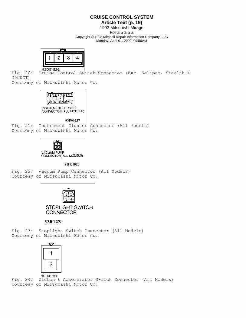
Fig. 20: Cruise Control Switch Connector (Exc. Eclipse, Stealth &3000GT)Courtesy of Mitsubishi Motor Co.
Fig. 21: Instrument Cluster Connector (All Models)Courtesy of Mitsubishi Motor Co.
Fig. 22: Vacuum Pump Connector (All Models)Courtesy of Mitsubishi Motor Co.
Fig. 23: Stoplight Switch Connector (All Models)Courtesy of Mitsubishi Motor Co.
Fig. 24: Clutch & Accelerator Switch Connector (All Models)Courtesy of Mitsubishi Motor Co.

CRUISE CONTROL SYSTEMArticle Text (p. 20)
1992 Mitsubishi MirageFor a a a a a
Copyright © 1998 Mitchell Repair Information Company, LLCMonday, April 01, 2002 09:56AM
Fig. 25: Inhibitor Switch Connector (All Models)Courtesy of Mitsubishi Motor Co.
Fig. 26: Motor Position Sensor Connector (Exc. Eclipse, Stealth &3000GT)Courtesy of Mitsubishi Motor Co.
Fig. 27: Throttle Position Sensor Connector (All Models)Courtesy of Mitsubishi Motor Co.
Fig. 28: Overdrive Switch Connector (All Models)Courtesy of Mitsubishi Motor Co.
Fig. 29: Cruise Control Switch Connector (Eclipse)Courtesy of Mitsubishi Motor Co.

CRUISE CONTROL SYSTEMArticle Text (p. 21)
1992 Mitsubishi MirageFor a a a a a
Copyright © 1998 Mitchell Repair Information Company, LLCMonday, April 01, 2002 09:56AM
Fig. 30: Overdrive Switch Connector (Eclipse)Courtesy of Mitsubishi Motor Co.
Fig. 31: Main Cruise Control Switch Connector (Stealth & 3000GT)Courtesy of Mitsubishi Motor Co.
Fig. 32: Cruise Control Relay Connector (1992 Stealth & 3000GT)Courtesy of Mitsubishi Motor Co.
CIRCUIT TESTS (ECLIPSE)
NOTE: To identify circuit connector terminals, See Figs. 19-32. For wiring diagrams, See appropriate chassis wiring diagram in this Section. For 1992 model wiring diagrams, See appropriate chassis wiring diagrams in the WIRING DIAGRAMS Section.
Test No. 1 (Power Supply Circuit) 1) When cruise control switch is turned to ON position,battery voltage should be present on terminal No. 2 of control unitconnector. If battery voltage is not present, check fuse No. 11. 2) If fuse is okay, repair harness. Control unit should begrounded at all times through terminals No. 8 and 14. If circuit isnot grounded, repair harness.
Test No. 2 (Set & Coast Switch Circuits)

CRUISE CONTROL SYSTEMArticle Text (p. 22)
1992 Mitsubishi MirageFor a a a a a
Copyright © 1998 Mitchell Repair Information Company, LLCMonday, April 01, 2002 09:56AM
When set switch is turned to ON position, voltage should notbe present on terminal No. 17 of control unit. When set switch isturned to OFF position, voltage should be present on terminal No. 17of control unit. If circuit does not test correctly, replace switch orrepair harness.
Test No. 3 (Resume Switch Circuit) When resume switch is turned to ON position, voltage shouldnot be present on terminal No. 18 of control unit. When resume switchis turned to off position, voltage should be present on terminal No.18 of control unit. If circuit does not test correctly, replace switchor repair harness.
Test No. 4 (Vehicle Speed Sensor Circuit) When vehicle moves slowly, voltage should alternate from zerovolts to 2 or more volts at terminal No. 19 of control unit. Ifcircuit does not test correctly, replace sensor or repair harness.
Test No. 5 (Vacuum Pump Circuit) 1) When release valve is in release mode, battery voltageshould be present on terminal No. 12 of control unit. When releasevalve is in acceleration or deceleration mode, voltage should not bepresent on terminal No. 12 of control unit. 2) When control valve is in release or deceleration modes,battery voltage should be present on terminal No. 13 of control unit.When control valve is in acceleration mode, battery voltage should notbe present on terminal No. 13 of control unit. 3) When vacuum pump is in release or deceleration mode,battery voltage should be present on terminal No. 26 of control unit.When vacuum pump is in acceleration mode, battery voltage should notbe present on terminal No. 26 of control unit. If circuit does nottest correctly, replace vacuum pump or repair harness.
Test No. 6 (Stoplight Switch Circuit) When brake pedal is pressed, battery voltage should bepresent on terminal No. 15 of control unit. When brake pedal isreleased, voltage should not be present on terminal No. 15 of controlunit. If circuit does not test correctly, replace switch or repairharness.
Test No. 7 (Inhibitor Switch Circuit) 1) When inhibitor switch is placed in "N" or "P", batteryvoltage should not be present on terminal No. 1 of control unit. 2) When inhibitor switch is placed in "D", "2", "L" or "R"position, battery voltage should be present on terminal No. 1 ofcontrol unit. If circuit does not test correctly, replace switch orrepair harness.
Test No. 8 (Clutch Switch Circuit) When clutch pedal is pressed, battery voltage should not bepresent on terminal No. 1 of control unit. When clutch pedal isreleased, voltage should be present on terminal No. 1 of control unit.

CRUISE CONTROL SYSTEMArticle Text (p. 23)
1992 Mitsubishi MirageFor a a a a a
Copyright © 1998 Mitchell Repair Information Company, LLCMonday, April 01, 2002 09:56AM
If circuit does not test correctly, replace switch or repair harness.
Test No. 9 (Accelerator Switch Circuit) 1) When ignition switch is in ON position, battery voltageshould be present on terminal No. 3 of control unit. When acceleratorpedal is pressed, battery voltage should not be present on terminalNo. 9 of control unit. 2) When accelerator pedal is released, battery voltage shouldbe present on terminal No. 9 of control unit. If circuit does not testcorrectly, replace switch or repair harness.
Test No. 10 (Overdrive Cancellation Circuit) 1) When ignition switch is in ON position, battery voltageshould be present on terminal No. 3 of control unit. When overdrive isactivated, battery voltage should be present on terminal No. 10 ofcontrol unit. 2) When overdrive is off, battery voltage should not bepresent on terminal No. 10 of control unit. When overdrive switch isin ON position, battery voltage should be present on terminal No. 11of control unit. 3) When overdrive switch is in OFF position, battery voltageshould not be present on terminal No. 11 of control unit. If circuitdoes not test correctly, replace switch or repair harness.
Test No. 11 (Throttle Position Sensor & Idle Switch Circuit) 1) When checking idle switch, if accelerator pedal ispressed, battery voltage should be present on terminal No. 4 ofcontrol unit. When accelerator pedal is released, battery voltageshould not be present on terminal No. 4 of control unit. 2) When checking throttle position sensor, if throttle valveis in idle position, .45-.55 volts should be present on terminal No. 5of control unit. When throttle valve is in wide open throttleposition, 4.5-5.5 volts should be present on terminal No. 5 of controlunit. If circuit does not test correctly, replace switch or repairharness.
CRUISE CONTROL SWITCHES, RELAYS & SENSORS TESTS
Resume & Set Switch (Colt, Colt 200, Mirage & Summit) 1) Remove knee protector or lower panel assembly and columncover. Disconnect 4-pin cruise control switch connector. For resumecircuit, check continuity between terminal No. 1 and ground wire. 2) For set circuit, check continuity between terminal No. 2and ground wire. If continuity is not present, replace cruise controlswitch.
Resume & Set Switch (Eclipse) 1) Remove knee protector and lower column cover. Disconnectcruise control switch connector. With switch in resume position,continuity should exist between terminals No. 13 and 19. 2) With switch in set position, continuity should existbetween terminals No. 13 and 8. If continuity is not present, replace

CRUISE CONTROL SYSTEMArticle Text (p. 24)
1992 Mitsubishi MirageFor a a a a a
Copyright © 1998 Mitchell Repair Information Company, LLCMonday, April 01, 2002 09:56AM
cruise control switch.
CAUTION: On Stealth and 3000GT, the capacitor in the SRS diagnostic unit holds enough voltage to deploy air bag even after battery cable has been disconnected. Remove negative battery cable and wait for more than 30 seconds before removing air bag module.
Resume & Set Switch (Stealth & 3000GT) 1) Remove air bag module. See AIR BAG MODULE under REMOVAL &INSTALLATION. Disconnect cruise control switch 2-pin connector. 2) With switch in OFF position, continuity should not bepresent between terminals. When switch is pulled toward you for cancelmode, zero ohms should be present. 3) When switch is in RESUME position, resistance should be820 ohms. When switch is in SET position, resistance should be 2700ohms. Replace cruise control switch if resistance is not correct.
Main Switch (Stealth & 3000GT) 1) Pry main switch bezel with switch from console. Checkcontinuity in each switch position. With switch in OFF position,continuity should be present between terminals No. 1 and 2 forillumination light circuit. See Figs. 19-32. 2) With switch in Neutral position, continuity should bepresent between terminals No. 1 and 2, and between terminals No. 4 and5. With switch in ON position, continuity should be present betweenterminals No. 1 and 2, and between terminals No. 3, 4 and 5. Ifcontinuity is not present, replace main switch.
Cruise Control Relay (1992 Stealth & 3000GT) 1) Remove relay. Relay is located behind center of dash,below radio. Continuity should be present between terminals No. 2 and4. See Figs. 19-32. 2) Apply battery voltage to terminal No. 2 and groundterminal No. 4. Continuity should be present between terminals No. 1and 3. If continuity is not correct, replace cruise control relay.
Brakelight/Stoplight Switch Disconnect switch connector. When brake pedal is pressed,continuity should exist between terminals No. 2 and 3. See Figs. 19-32. When brake pedal is released, continuity should exist betweenterminals No. 1 and 4. If continuity is not correct, replace switch.
Clutch Switch Disconnect switch connector. Continuity should be presentbetween clutch switch terminals when clutch pedal is pressed. Ifcontinuity is not correct, replace switch.
Inhibitor Switch Disconnect switch connector. Continuity should exist betweenconnector terminals No. 8 and 9 when shift lever is in "P" or "N". SeeFigs. 19-32. If continuity is not correct, replace switch.

CRUISE CONTROL SYSTEMArticle Text (p. 25)
1992 Mitsubishi MirageFor a a a a a
Copyright © 1998 Mitchell Repair Information Company, LLCMonday, April 01, 2002 09:56AM
Throttle Position Switch 1) Disconnect throttle position sensor connector. Measureresistance between terminals No. 1 and 4. See Figs. 19-32. Resistanceshould be 3.5-6.5 ohms. 2) Connect an analog voltmeter between terminals No. 2 and 4.See Figs. 19-32. Operate throttle valve slowly from idle to wide openthrottle. Resistance should change smoothly as throttle valve isopened and closed. Replace throttle position sensor as necessary.
Idle Position Switch 1) Disconnect switch connector. Idle position switch isincorporated in throttle position switch. Continuity should existbetween terminals No. 3 and 4 with accelerator pedal released. SeeFigs. 19-32. 2) With accelerator pedal pressed, continuity should not bepresent between terminals No. 3 and 4. Replace idle position switch ifcontinuity is not correct.
ACCELERATOR SWITCH TEST
NOTE: Accelerator pedal switch testing information is not available from manufacturer.
VACUUM PUMP ASSEMBLY TEST
Solenoid Valves Remove vacuum pump connector. Resistance should be 50-60 ohmsbetween terminals No. 1 and 2, and between terminals No. 1 and 3. SeeFigs. 19-32. Ensure solenoid valve makes operating noise when batteryvoltage is applied between terminals No. 1 and 2, and betweenterminals No. 1 and 3. If solenoid valve does not make noise, replacevacuum pump assembly.
Pump Motor Remove vacuum pump connector. Apply battery voltage betweenterminals No. 1 and 4. See Figs. 19-32. Motor should operate. Replacemotor if it does not operate.
ACTUATOR TEST
Remove actuator. Apply vacuum to actuator. Actuator linkageholder should move more than 1.38" (35 mm). Actuator diaphragm shouldhold vacuum.
VEHICLE SPEED SENSOR
Colt, Colt 200, Eclipse, Mirage & Summit 1) Remove instrument cluster. See INSTRUMENT CLUSTER underREMOVAL & INSTALLATION. On Colt, Colt 200, Mirage and Summit, checkcontinuity between vehicle speed sensor terminals No. 1 and 2. SeeFigs. 33-36. On Eclipse, check continuity between vehicle speed sensor

CRUISE CONTROL SYSTEMArticle Text (p. 26)
1992 Mitsubishi MirageFor a a a a a
Copyright © 1998 Mitchell Repair Information Company, LLCMonday, April 01, 2002 09:56AM
terminals. 2) Ensure continuity pulses on and off 4 times per revolutionof speedometer shaft connection. If continuity is not as specified,replace sensor.
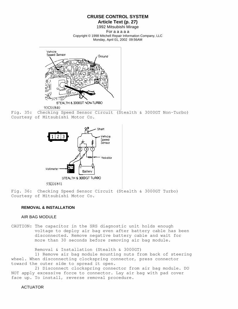
Stealth & 3000GT (Non-Turbo) Remove instrument cluster. See INSTRUMENT CLUSTER underREMOVAL & INSTALLATION. Connect circuit tester to speed sensorterminals. See Figs. 33-36. When speedometer shaft is turned severaltimes, circuit tester should turn on and off several times. Replacespeed sensor if operation is not correct.
Stealth & 3000GT (Turbo) Remove speed sensor. See INSTRUMENT CLUSTER under REMOVAL &INSTALLATION. Connect battery, resistor (3-10 ohms) and voltmeter tospeed sensor terminals. See Figs. 33-36. When speedometer shaft isturned several times, voltage should pulse 4 times each revolution.Replace speed sensor if operation is not correct.
Fig. 33: Checking Speed Sensor Circuit (Colt, Colt 200, Mirage &SummitCourtesy of Mitsubishi Motor Co.
Fig. 34: Checking Speed Sensor Circuit (Eclipse)Courtesy of Mitsubishi Motor Co.
CRUISE CONTROL SYSTEMArticle Text (p. 27)
1992 Mitsubishi MirageFor a a a a a
Copyright © 1998 Mitchell Repair Information Company, LLCMonday, April 01, 2002 09:56AM
Fig. 35: Checking Speed Sensor Circuit (Stealth & 3000GT Non-Turbo)Courtesy of Mitsubishi Motor Co.
Fig. 36: Checking Speed Sensor Circuit (Stealth & 3000GT Turbo)Courtesy of Mitsubishi Motor Co.
REMOVAL & INSTALLATION
AIR BAG MODULE
CAUTION: The capacitor in the SRS diagnostic unit holds enough voltage to deploy air bag even after battery cable has been disconnected. Remove negative battery cable and wait for more than 30 seconds before removing air bag module.
Removal & Installation (Stealth & 3000GT) 1) Remove air bag module mounting nuts from back of steeringwheel. When disconnecting clockspring connector, press connectortoward the outer side to spread it open. 2) Disconnect clockspring connector from air bag module. DONOT apply excessive force to connector. Lay air bag with pad coverface up. To install, reverse removal procedure.
ACTUATOR
CRUISE CONTROL SYSTEMArticle Text (p. 28)
1992 Mitsubishi MirageFor a a a a a
Copyright © 1998 Mitchell Repair Information Company, LLCMonday, April 01, 2002 09:56AM
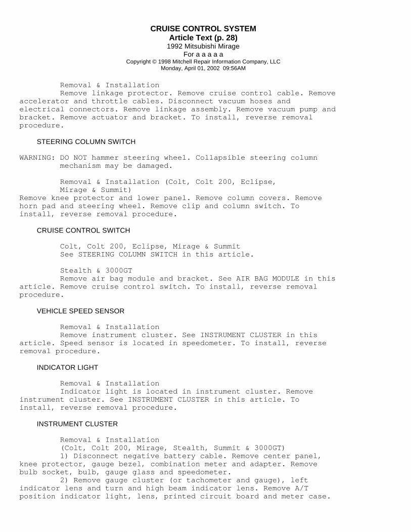
Removal & Installation Remove linkage protector. Remove cruise control cable. Removeaccelerator and throttle cables. Disconnect vacuum hoses andelectrical connectors. Remove linkage assembly. Remove vacuum pump andbracket. Remove actuator and bracket. To install, reverse removalprocedure.
STEERING COLUMN SWITCH
WARNING: DO NOT hammer steering wheel. Collapsible steering column mechanism may be damaged.
Removal & Installation (Colt, Colt 200, Eclipse, Mirage & Summit)Remove knee protector and lower panel. Remove column covers. Removehorn pad and steering wheel. Remove clip and column switch. Toinstall, reverse removal procedure.
CRUISE CONTROL SWITCH
Colt, Colt 200, Eclipse, Mirage & Summit See STEERING COLUMN SWITCH in this article.
Stealth & 3000GT Remove air bag module and bracket. See AIR BAG MODULE in thisarticle. Remove cruise control switch. To install, reverse removalprocedure.
VEHICLE SPEED SENSOR
Removal & Installation Remove instrument cluster. See INSTRUMENT CLUSTER in thisarticle. Speed sensor is located in speedometer. To install, reverseremoval procedure.
INDICATOR LIGHT
Removal & Installation Indicator light is located in instrument cluster. Removeinstrument cluster. See INSTRUMENT CLUSTER in this article. Toinstall, reverse removal procedure.
INSTRUMENT CLUSTER
Removal & Installation (Colt, Colt 200, Mirage, Stealth, Summit & 3000GT) 1) Disconnect negative battery cable. Remove center panel,knee protector, gauge bezel, combination meter and adapter. Removebulb socket, bulb, gauge glass and speedometer. 2) Remove gauge cluster (or tachometer and gauge), leftindicator lens and turn and high beam indicator lens. Remove A/Tposition indicator light, lens, printed circuit board and meter case.

CRUISE CONTROL SYSTEMArticle Text (p. 29)
1992 Mitsubishi MirageFor a a a a a
Copyright © 1998 Mitchell Repair Information Company, LLCMonday, April 01, 2002 09:56AM
To install, reverse removal procedure.
Eclipse 1) Disconnect negative battery cable. Remove cluster cover.Remove cluster mounting screws. Remove cluster by turning upper parttoward front. Disconnect all necessary electrical connectors. Removeinstrument cluster. 2) Disconnect speedometer cable at transaxle end. Pullspeedometer cable slightly toward vehicle interior. Release adapter byturning left or right, and remove adapter. To install, reverse removalprocedure.
CONTROL UNIT
Removal & Installation (Colt, Colt 200, Mirage & Summit) Cruise control unit is located behind left side of lowerdash, behind fuse block. Remove mounting screws and remove controlunit. To install, reverse removal procedure.
Removal & Installation (Eclipse) Cruise control unit is located behind left kick panel. Removekick panel and cruise control unit. To install, reverse removalprocedure.
Removal & Installation (Stealth & 3000GT) Cruise control unit is located behind right kick panel.Remove kick panel and cruise control unit. To install, reverse removalprocedure.
WIRING DIAGRAMS
For 1992 model wiring diagrams, See appropriate chassiswiring diagram in the WIRING DIAGRAMS Section.

CRUISE CONTROL SYSTEMArticle Text (p. 30)
1992 Mitsubishi MirageFor a a a a a
Copyright © 1998 Mitchell Repair Information Company, LLCMonday, April 01, 2002 09:56AM
Fig. 37: 1991 Speed Control System Wiring Diagram (Colt, Colt 200,Mirage & Summit)Courtesy of Mitsubishi Motor Co.
CRUISE CONTROL SYSTEMArticle Text (p. 31)
1992 Mitsubishi MirageFor a a a a a
Copyright © 1998 Mitchell Repair Information Company, LLCMonday, April 01, 2002 09:56AM
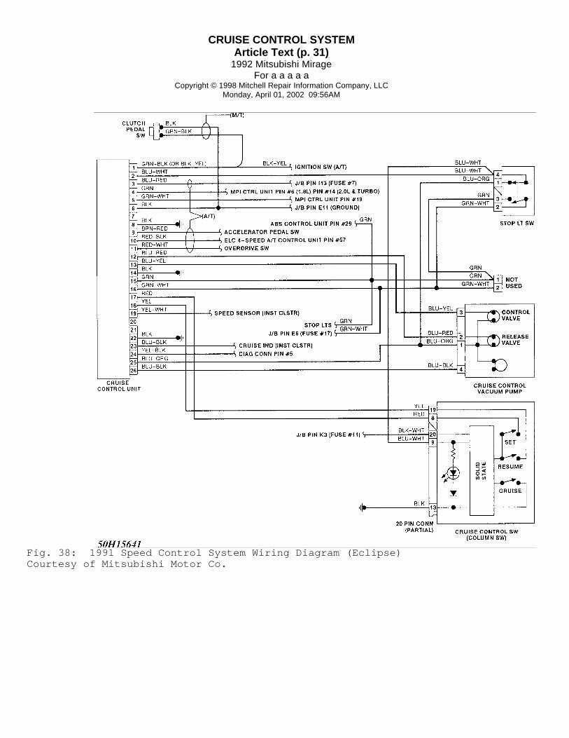
Fig. 38: 1991 Speed Control System Wiring Diagram (Eclipse)Courtesy of Mitsubishi Motor Co.

CRUISE CONTROL SYSTEMArticle Text (p. 32)
1992 Mitsubishi MirageFor a a a a a
Copyright © 1998 Mitchell Repair Information Company, LLCMonday, April 01, 2002 09:56AM
Fig. 39: 1991 Speed Control System Wiring Diagram (Stealth & 3000GT)Courtesy of Mitsubishi Motor Co.
END OF ARTICLE