cross section - impact design
TRANSCRIPT

Cross Section
Creator
CSC features:
CSC Main view – 3D
environment
CSC – Import procedures
Import FE (Ls-Dyna *.k and
*.key file format)
Import RADIOSS file
Import *.stl file format
Create Cross Sections from FE
Parts
New Cross Section in CCC
The company Impact Design Europe is glad to inform
you about the development of CROSS SECTION
CREATOR
CROSS SECTION CREATOR (CSC) provides a user
friendly 3D environment which enables import of a FE
mesh model and fast and easy extraction of cross
sections. Such newly created cross sections can be
saved and that optimized and calculated in the Crash
Cad Calculate software.
Cross Section Creator which enriches the
functionalities and capabilities of Crash Cad Calculate
(CCC), provides the possibility of fast and easy
extraction of Cross Sections from a mesh model and
consequently closes the optimization and design loop.
We will very much appreciate all of your comments
and suggestions, which can be sent to our e-mail
address: [email protected]. We will try to
meet your expectations in the future versions of CSC
software.
Best Regards,
Agata Abramowicz Sokoll
Cross Section Creator – Main View
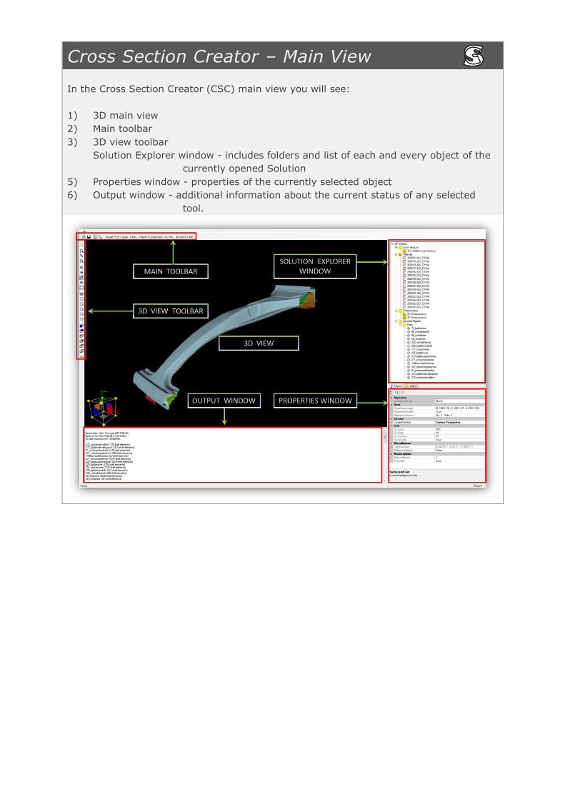
In the Cross Section Creator (CSC) main view you will see:
1) 3D main view
2) Main toolbar
3) 3D view toolbar
4) Solution Explorer window - includes folders and list of each and every object of the
currently opened Solution
5) Properties window - properties of the currently selected object
6) Output window - additional information about the current status of any selected
tool.
CSC – Import Procedures
In Cross Section Creator (CSC) you will find several import possibilities.
All import features are easily accessible through the Main Toolbar.
CSC provides the possibility to import mesh models in the following file format: .rad, .k;
.key; .stl)
Import FE (Ls-Dyna *.k file)
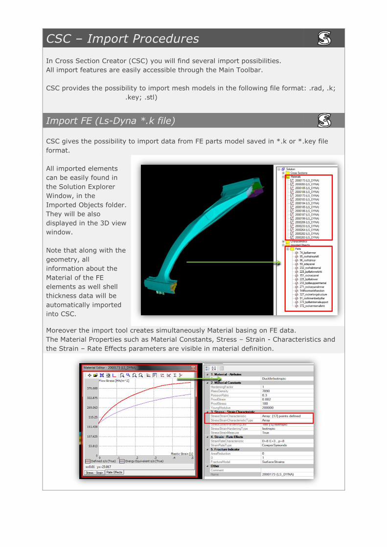
CSC gives the possibility to import data from FE parts model saved in *.k or *.key file
format.
All imported elements
can be easily found in
the Solution Explorer
Window, in the
Imported Objects folder.
They will be also
displayed in the 3D view
window.
Note that along with the
geometry, all
information about the
Material of the FE
elements as well shell
thickness data will be
automatically imported
into CSC.
Moreover the import tool creates simultaneously Material basing on FE data.
The Material Properties such as Material Constants, Stress – Strain - Characteristics and
the Strain – Rate Effects parameters are visible in material definition.

Import from RADIOSS
CSC provides the possibility of easy import of FE Parts from RADIOSS file.
All imported elements can be easily found in the Solution Explorer Window, in the
Imported Objects folder. They will be also displayed in the 3D view window.
Note that along with the geometry, information about the Material of the FE elements as
well shell thickness data will be automatically imported into CSC.
Import *.stl file
Additionally Cross Section Creator enables import of mesh models saved in *.stl file
format.
Imported mesh model will be now visible in the main 3D view.
It will be also automatically added to the “Imported Objects” branch of the Solution
Explorer three.
Please note that in case of a *.stl file import, import of materials is not available.
Moreover, information about shell thickness will be also inaccessible.
Create Cross Section from FE Part
CSC provides a special Create Cross Section from FE Part tool dedicated to enable the
user to build even complex cross section geometry from previously imported mesh
models for further calculations and edition in the CCC software.
With the usage of Create Cross Sections from FE Part tool extraction of cross section is
possible after a 3-click procedure.
The User has the possibility to easily work on number of cross sections extracted from
most crucial parts of the analyzed structure.
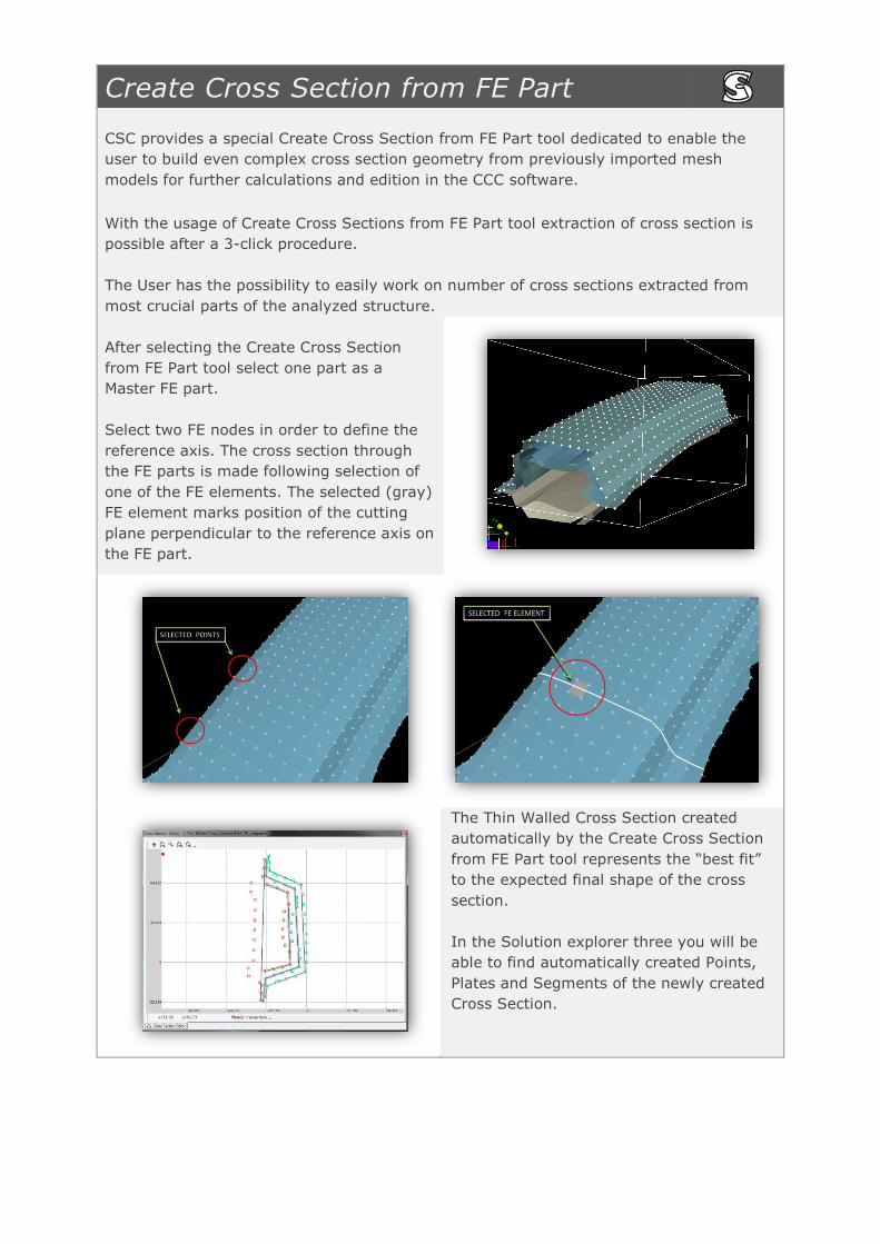
After selecting the Create Cross Section
from FE Part tool select one part as a
Master FE part.
Select two FE nodes in order to define the
reference axis. The cross section through
the FE parts is made following selection of
one of the FE elements. The selected (gray)
FE element marks position of the cutting
plane perpendicular to the reference axis on
the FE part.
The Thin Walled Cross Section created
automatically by the Create Cross Section
from FE Part tool represents the “best fit”
to the expected final shape of the cross
section.
In the Solution explorer three you will be
able to find automatically created Points,
Plates and Segments of the newly created
Cross Section.

New Cross Section in CCC
Cross Section Creator which enriches the functionalities and capabilities of Crash Cad
Calculate (CCC), provides the possibility of fast and easy extraction of Cross Sections
from a mesh model and consequently closes the optimization and design loop.
CSC offers a user friendly 3D environment which allows import of a FE model and
creation of Cross Sections after a simple, 3-click operation. Such cross sections can be
than transferred into the Crash Cad Calculate 2D environment, where further calculations
and optimization routines can be done.
Edition, modifications, optimization and calculations of Cross Sections created from z
mesh model are available after opening a CSC file in the CCC software
Cross section geometry created automatically by CSC is already divided into Points,
Plates and Segments, which can be found in the Solution Explorer window.
However in case of more complex Cross Sections the user interaction is necessary to
complete the Cross Section according to the Macro Element discretization requirements.