cross-regulation assessment of dido buck-boost...
TRANSCRIPT

energies
Article
Cross-Regulation Assessment of DIDO Buck-BoostConverter for Renewable Energy Application
Deepak Elamalayil Soman * and Mats Leijon
Division of Electricity, Department of Engineering Sciences, Angstrom Laboratory, Box: 534, Uppsala University,SE-75121 Uppsala, Sweden; [email protected]* Correspondence: [email protected]
Received: 5 April 2017; Accepted: 21 June 2017; Published: 25 June 2017
Abstract: When medium- or high-voltage power conversion is preferred for renewable energysources, multilevel power converters have received much of the interest in this area as methods forenhancing the conversion efficiency and cost effectiveness. In such cases, multilevel, multi-inputmulti-output (MIMO) configurations of DC-DC converters come to the scenario for integratingseveral sources together, especially considering the stringent regulatory needs and the requirementof multistage power conversion systems. Considering the above facts, a three-level dual input dualoutput (DIDO) buck-boost converter, as the simplest form of MIMO converter, is proposed in thispaper for DC-link voltage regulation. The capability of this converter for cross regulating the DC-linkvoltage is analyzed in detail to support a three-level neutral point clamped inverter-based gridconnection in the future. The cross-regulation capability is examined under a new type of pulse delaycontrol (PDC) strategy and later compared with a three-level boost converter (TLBC). Compared toconventional boost converters, the high-voltage three-level buck boost converter (TLBBC) with PDCexhibits a wide controllability range and cross regulation capability. These enhanced features areextremely important for better regulating variable output renewable energy sources such as solar,wind, wave, marine current, etc. The simulation and experimental results are provided to validatethe claim.
Keywords: dual input dual output (DIDO) converter; three-level buck boost converter (TLBBC); pulsedelay control (PDC); neutral point clamped inverter; cross-regulation; renewable energy conversion
1. Introduction
DC-DC converters have been widely used or proposed for different applications, recently forgrid-tied renewable power conversion systems [1–4]. For the most part their applications are projectedfor photovoltaic (PV) systems [5–8]. However, they can be adopted for use with any renewable energysources that have a DC-conversion stage. Since the power transmission from distant or offshorerenewables is efficient in medium or high voltage, conventional converter topologies are replaced bytheir multilevel counterparts. This power transfer is often fulfilled by multiple power conversion stages.The DC-DC converters regulate the DC-link voltage in common DC-link systems. The normal boostoperation used for supporting neutral point clamped (NPC) inverters in grid-connected photovoltaicsystems can be replaced with multilevel DC-DC converters for improving the overall performance ofthe system. In addition, they play a key role in resolving the drawbacks of certain multilevel invertertopologies. For example, many topologies are subjected to circulating current or capacitor voltageimbalance problems. These issues can either be solved by modulation strategies or by additionalhardware circuits. Several DC-DC converter configurations are proposed for voltage balancing [9–15].A three-level boost converter with a new PDC strategy is proposed for the DC-link voltage regulationand neutral point voltage balancing for three-level neutral point clamped (NPC) inverter; see [13,14].
Energies 2017, 10, 846; doi:10.3390/en10070846 www.mdpi.com/journal/energies

Energies 2017, 10, 846 2 of 11
In [14], the improvement in converter cross-regulation capability with PDC for TLBC is compared tothe conventional three-level boost control and enhancements are listed clearly.
In many renewable energy conversion scenarios, the generated voltage output can become higheror lower than the rated DC-link voltage of the power converter system. In such cases, it is vital to haveboth buck and boost capabilities for the DC-DC converter to maximize the system utilization. In suchsituations, the conventional boost and the TLBC become inadequate. Considering the above aspects,the current work proposes DIDO-type TLBBC with a PDC strategy for enhanced power conversionand balancing performance.
Section 2 discusses the basic TLBBC circuit with its four distinct operating modes andcharacteristics. Ten different operational cases of TLBBC and their contributions for voltage crossregulation, along with the equations for neutral voltage calculation in each case is presented in Section 3.Validation of analytical results using simulations are also presented in this section. A brief discussionof closed-loop controller design is given in Section 4, while the simulation results are presented inSection 5. Cross-regulation comparisons of TLBC and TLBBC are presented with 3D plots in Section 6.In Section 7, experimental setup and test results are described along with a comparison of neutralvoltage from analytical, simulation and experimental methods. Final conclusions from the work arepresented in Section 8.
2. Three-Level Buck-Boost Converter—Modes of Operation
This section discusses about the basic TLBBC circuit with the four operating modes [16], as shownin Figure 1. Depending on the position of the switches S1 and S2, there are four modes of operation forthe TLBBC: mode1, mode2, mode3, and mode4. Each mode of operation with corresponding voltageand current equations are presented below, where p denotes the time derivative d/dt. Figure 1 showsthe current paths during each mode in red.
Energies 2017, 10, 846 2 of 11
neutral point clamped (NPC) inverter; see [13,14]. In [14], the improvement in converter cross-regulation capability with PDC for TLBC is compared to the conventional three-level boost control and enhancements are listed clearly.
In many renewable energy conversion scenarios, the generated voltage output can become higher or lower than the rated DC-link voltage of the power converter system. In such cases, it is vital to have both buck and boost capabilities for the DC-DC converter to maximize the system utilization. In such situations, the conventional boost and the TLBC become inadequate. Considering the above aspects, the current work proposes DIDO-type TLBBC with a PDC strategy for enhanced power conversion and balancing performance.
Section 2 discusses the basic TLBBC circuit with its four distinct operating modes and characteristics. Ten different operational cases of TLBBC and their contributions for voltage cross regulation, along with the equations for neutral voltage calculation in each case is presented in Section 3. Validation of analytical results using simulations are also presented in this section. A brief discussion of closed-loop controller design is given in Section 4, while the simulation results are presented in Section 5. Cross-regulation comparisons of TLBC and TLBBC are presented with 3D plots in Section 6. In Section 7, experimental setup and test results are described along with a comparison of neutral voltage from analytical, simulation and experimental methods. Final conclusions from the work are presented in Section 8.
2. Three-Level Buck-Boost Converter—Modes of Operation
This section discusses about the basic TLBBC circuit with the four operating modes [16], as shown in Figure 1. Depending on the position of the switches S1 and S2, there are four modes of operation for the TLBBC: mode1, mode2, mode3, and mode4. Each mode of operation with corresponding voltage and current equations are presented below, where p denotes the time derivative / . Figure 1 shows the current paths during each mode in red.
Figure 1. Three-level buck boost converter (TLBBC) circuit with four operating modes based on the switching states of the switches S1 and S2, defined as mode1 to mode4: (a) Mode1: S1 and S2 ON, (b) Mode2: S1 ON and S2 OFF, (c) Mode3: S1 OFF and S2 ON, (d) Mode4: S1 and S2 OFF.
2.1. Mode1: S1 and S2 ON
In Mode1, both S1 and S2 are ON. The inductor L is charged by the sources, Vin1 and Vin2 and hence the current via inductor, , increases linearly. The capacitors C1 and C2 discharge through load resistors R1 and R2, as shown in Figure 1a. The steady state voltage and current Equations are given by Equation (1):
L
C2
R1C1
R2
Vin1
S1
S2
D1
D2
C
C
Vin2
+
+
+
+
-
-
-
-iL
(c)
L
C2
R1C1
R2
Vin1
S1
S2
D1
D2
C
C
Vin2
+
+
+
+
-
-
-
-iL
(a)
L
C2
R1C1
R2
Vin1
S1
S2
D1
D2
C
C
Vin2
+
+
+
+
-
-
-
-iL
(b)
L
C2
R1C1
R2
Vin1
S1
S2
D1
D2
C
C
Vin2
+
+
+
+
-
-
-
-iL
(d)
L
C2
R1C1
R2
Vin1
S1
S2
D1
D2
C
C
Vin2
+
+
+
+
-
-
-
-iL
(c)
L
C2
R1C1
R2
Vin1
S1
S2
D1
D2
C
C
Vin2
+
+
+
+
-
-
-
-iL
(a)
L
C2
R1C1
R2
Vin1
S1
S2
D1
D2
C
C
Vin2
+
+
+
+
-
-
-
-iL
(b)
L
C2
R1C1
R2
Vin1
S1
S2
D1
D2
C
C
Vin2
+
+
+
+
-
-
-
-iL
(d)
Figure 1. Three-level buck boost converter (TLBBC) circuit with four operating modes based on theswitching states of the switches S1 and S2, defined as mode1 to mode4: (a) Mode1: S1 and S2 ON,(b) Mode2: S1 ON and S2 OFF, (c) Mode3: S1 OFF and S2 ON, (d) Mode4: S1 and S2 OFF.
2.1. Mode1: S1 and S2 ON
In Mode1, both S1 and S2 are ON. The inductor L is charged by the sources, Vin1 and Vin2 andhence the current via inductor, iL, increases linearly. The capacitors C1 and C2 discharge through load

Energies 2017, 10, 846 3 of 11
resistors R1 and R2, as shown in Figure 1a. The steady state voltage and current Equations are givenby Equation (1):
piL =Vin1 + Vin2
L; pvC1 = − vC1
R1C1; pvC2 = − vC2
R2C2(1)
where vC1 and vC2 are the voltages across the capacitors C1 and C2, respectively, and R1 and R2 arethe load resistors.
2.2. Mode2: S1 ON and S2 OFF
In Mode2, S1 remains ON whereas S2 is turned OFF, as shown in Figure 1b. The inductor L ischarged by the source, Vin1 and current flows from input via inductor L to resistor R2. The capacitorC2 is charged whereas C1 discharges through resistor R1. The voltage across C1 decreases and that ofC2 increases, and thereby creates an imbalance at the output. The steady state Equations are given byEquation (2):
piL =Vin1 − vC2
L; pvC1 = − vC1
R1C1; pvC2 =
iLR2 − vC2
R2C2(2)
2.3. Mode3: S1 OFF and S2 ON
This mode is quite like the previous mode. The current flows from input Vin2 via inductor Lto resistor R1. The capacitor C1 is charged while C2 discharges through resistor R2. In this mode,the voltage across C1 increases and C2 decreases, resulting in an imbalance. The flow of current isshown in Figure 1c. The steady state Equations are given by Equation (3):
piL =Vin2 − vC1
L; pvC1 =
iLR1 − vC1
R1C1; pvC2 = − vC2
R2C2. (3)
2.4. Mode4: S1 and S2 OFF
If both S1 and S2 are OFF, then there is no direct energy transfer from source to load. The inductorL discharges to the load and, hence, the current iL decreases linearly. There will not be any unbalancedvoltage at the output. The flow of current is shown in Figure 1d. The state space Equations are givenby Equation (4):
piL =vC1 + vC2
L; pvC1 =
iLR1 − vC1
R1C1; pvC2 =
iLR2 − vC2
R2C2(4)
form the modes of operation listed above; it is clear that the TLBBC has different characteristicsduring each mode. The modes 1 and 4 are primarily responsible for the conventional buck-boost typeconverter operation, while the modes 2 and 3 are capable for the cross-regulation/voltage balancing.
3. Operational Cases, Open-Loop Control Equations and Cross-Regulation Verification
From the detailed analysis of TLBBC operation using different combination, sequencing andtiming of TLBBC operating modes, it is found that the converter can go through 10 different operationalcases during its entire range of operation as shown in Table 1. The analysis is based on the assumptionthat the converter stays in continuous current mode (CCM) during all the cases of operation. Thesecases can be used for the mathematical modeling of the DC-link voltage and thereby enable the designof the controller. The inductor ripple current is different in each case. Therefore, the conventional statespace averaging technique cannot be applied to all the cases. The inductor ripple current averagingtechnique with state space averaging method is the best suited [14,17]. Using this method, the voltagedifference ∆V for each case is modeled. Table 1 also gives the expression of ∆V for all 10 cases ofoperation of the TLBBC.
It should be noted that the case I and case IV with only two modes of operation in each casewill not be able to contribute for cross regulation purposes. However, they can be used for thenormal buck-boost operation. In particular, case I, which includes mode1 and mode4, is similar to
Energies 2017, 10, 846 4 of 11
the conventional buck-boost converter operation and can be used for the total voltage control ofthe TLBBC output by using a duty ratio control similar to the conventional buck-boost regulation.Case IV is, however, not present in the conventional converter, and it charges and discharges the twocapacitors equally during alternative switching modes. This causes the average voltage change ina cycle to become zero and cannot contribute to cross-regulation application. All the other cases, exceptcase I and case IV, can contribute to cross-regulation purposes, and the intelligent use of these casesduring closed loop control of TLBBC can enhance the cross-regulation capabilities of the TLBBC whileoptimizing the performance and stability.
Table 1. TLBBC operational cases and expressions for neutral voltage.
Cases Mode Sequencing ∆V
I mode1→mode4 0II mode1→mode3→mode4→mode2 −λ[λ− 2d(1− d)]ΘIII mode1→mode2→mode4→mode3 (1− λ)(2d(d− 1) + 1− λ)ΘIV mode2→mode3 0V mode1→mode2→mode3 −(2d− 1)(1− d)2Θ
VI mode1→mode3→mode1→mode2 (2λ− 1)(1− d)2ΘVII mode1→mode3→mode2 −λ2(1− 2λ)ΘVIII mode2→mode4→mode3 (1− 2λ)(1− λ)2ΘIX mode2→mode4→mode3→mode4 (1− 2λ)d2ΘX mode2→mode3→mode4 λ2(1− d− λ)Θ
Where d is the duty ratio of the switches, λ is the pulse delay ratio (delay between switch gatepulses/switching period) and Θ is a function of input and output voltages, which is defined inEquation (5):
Θ =RTs
2L[vC1 + vC2 + Vin1 + Vin2] (5)
The voltage imbalance, ∆V, obtained mathematically, can be compared with the value givenby the simulation for each case. Figure 2 shows the value of ∆V obtained from calculation and inopen-loop simulation. It is shown that both the results are almost equal. The simulation parametersused are given in Table 2.
Table 2. Simulation parameters.
Parameter Name Value
Input voltages Vin1, Vin2 25 VSwitching frequency, fs 5 kHz
Input capacitance, C 5 mFInductor, L 200 µH
Output capacitance, C1, C2 1 mFLoad resistance, R1, R2 2 Ω
Vf orward [insulated gate bipolar transistor(IGBT) and diode] 1 mV

Energies 2017, 10, 846 5 of 11Energies 2017, 10, 846 5 of 11
Figure 2. The voltage imbalance ∆V from mathematical analysis and simulations, corresponding to each operational cases of TLBBC: (a) Case 1; (b) Case 2; (c) Case 3; (d) Case 4; (e) Case 5; (f) Case 6; (g) Case 7; (h) Case 8; (i) Case 9; (j) Case 10.
4. Closed-Loop Controller Modelling
The DC-link voltage regulation is carried out by using the buck-boost capability of the system very similar to the conventional buck-boost converter control. The steady state output voltage, V0, of the buck-boost converter can be calculated using the input voltage, Vin, and the duty ratio, d, as shown in Equation (6). Depending on the value of d, the converter either increases or decreases the voltage given to the input. = (1 − ) (6)
To get the desired output voltage for a varying source voltage, the duty ratio must be controlled. The proportional integral (PI) controller computes the value of duty ratio, d, required for achieving the desired output voltage. The Equation of the controller for voltage regulation is given by (7): = + (7)
Figure 2. The voltage imbalance ∆V from mathematical analysis and simulations, corresponding toeach operational cases of TLBBC: (a) Case 1; (b) Case 2; (c) Case 3; (d) Case 4; (e) Case 5; (f) Case 6;(g) Case 7; (h) Case 8; (i) Case 9; (j) Case 10.
4. Closed-Loop Controller Modelling
The DC-link voltage regulation is carried out by using the buck-boost capability of the systemvery similar to the conventional buck-boost converter control. The steady state output voltage, V0,of the buck-boost converter can be calculated using the input voltage, Vin, and the duty ratio, d, asshown in Equation (6). Depending on the value of d, the converter either increases or decreases thevoltage given to the input.
V0 = Vind
(1− d)(6)
Energies 2017, 10, 846 6 of 11
To get the desired output voltage for a varying source voltage, the duty ratio must be controlled.The proportional integral (PI) controller computes the value of duty ratio, d, required for achieving thedesired output voltage. The Equation of the controller for voltage regulation is given by (7):
d = kp1ev + ki1
∫evdt (7)
where kp1 and ki1 are the proportional and integral controller parameters, and the error, ev = Vre f −V0;Vre f , is the desired DC-link voltage, and V0 is the actual output voltage.
In TLBBC, the two switches are operated with the same duty ratio. The phase between the controlsignals of the switches is varied to minimize the neutral point voltage ideally to zero. The gate signalof one switch is kept constant, while the phase of the other signal is varied. The voltage deferencebetween the output capacitors, ∆V, is sensed and is used in a PI controller to calculate a pulse delayratio, as shown in Equation (8). This delay is given to one of the switch pulse signal to move it eitherforward or backward with respect to the other pulse signal in order to compensate for the neutralpoint voltage.
λ = kp2e∆v + ki2
∫e∆vdt (8)
where kp2 and ki2 are the PI controller parameters, e∆v = ∆Vre f − ∆V.Applying perturbations to the state variables, the expression of the neutral point voltage for AC
analysis can be formulated. Considering case 2 for illustration, the system transfer function is given asshown in Equation (9):
G =∆Vλ
=[2d(1− d)− 2λ] VinT
2(1− d)LC(
s + 1RC
) (9)
where T is the switching period. Since a PI controller is used, the closed-loop transfer function Gc isgiven by Equation (10):
Gc =
(kp2 +
ki2s
)[2d(1− d)− 2λ] VinT
2(1− d)LC(
s + 1RC
) (10)
To find the value of kp2 and ki2, equate the characteristic equation of (10) to zero. The controllercan be tuned using these values. For example, in case II, the values of kp2 and ki2 are 0.1596 and 33.9605,respectively. It is observed that the same value of kp2 and ki2 satisfies other cases of the operation of theTLBBC as well. The simulation results show the maximum values of ∆V that the system can achievewith the feasible values of d and λ.
5. Simulation Results
Depending on the switching states, the TLBBC can be operated either as a normal buck-boostconverter or as a cross-voltage compensator. The operating regions of the converter are determinedby the duty ratio of the switch-gate signals and the pulse delay between them. Duty ratio is used forconventional buck-boost action and pulse delay gives the voltage cross regulation. To analyze theseoperations, the TLBBC circuit is simulated for a switching frequency of 5 kHz in MATLAB/Simulinkunder ideal conditions. Table 2 shows the specifications used for the simulations. For a step variationof the reference voltage ∆V from 1 V to 3.9 V, the system follows the input and gives the maximumresponse. The corresponding pulse delay ratio is just below 0.25. Figure 3 shows the correspondingwaveforms. The settling time is 0.03 s. For values greater than or equal to 4 V, the converter saturatesand the system starts oscillating, as shown in Figure 4a. The corresponding pulse delay variation isshown in Figure 4b.

Energies 2017, 10, 846 7 of 11Energies 2017, 10, 846 7 of 11
Figure 3. Maximum values of (a) capacitor voltage imbalance ∆V, and (b) corresponding pulse delay ratio λ.
Figure 4. Values on controller saturation (a) capacitor voltage difference ∆V, and (b) pulse delay ratio λ.
6. Comparison with Three-Level Boost Converter
The cross-regulation capabilities of a TLBBC and a three-level boost converter (TLBC) are compared under the PDC control method. The maximum cross-regulation voltages are calculated for all the 10 cases. The corresponding 3D-plots are shown below. For TLBC, the maximum normalized cross-regulation voltage is ±0.0625; see Figure 5. For TLBBC, this value is ±0.1467; see Figure 6. It shows that the TL buck-boost converter has better cross-regulation capability compared to the TL boost converter under same cross-voltage regulation method.
The cross-regulation voltage values in the figures below indicate the theoretical maximum for each duty ratio and pulse delay ratio. However, in practical scenarios, these values can be lower than that calculated here. The peracetic drops, the component lead impedances and losses in the switches and diodes restrict the converter to achieve these peak values. The parameters used for this simulation is also the same as the parameters used for the previous simulations and listed in Table 2.
Figure 5. Normalized cross-regulation voltage for three-level boost converter.
Nor
mal
ized
Neu
tral v
olta
ge (V
np,n
orm
)
Figure 3. Maximum values of (a) capacitor voltage imbalance ∆V, and (b) corresponding pulse delayratio λ.
Energies 2017, 10, 846 7 of 11
Figure 3. Maximum values of (a) capacitor voltage imbalance ∆V, and (b) corresponding pulse delay ratio λ.
Figure 4. Values on controller saturation (a) capacitor voltage difference ∆V, and (b) pulse delay ratio λ.
6. Comparison with Three-Level Boost Converter
The cross-regulation capabilities of a TLBBC and a three-level boost converter (TLBC) are compared under the PDC control method. The maximum cross-regulation voltages are calculated for all the 10 cases. The corresponding 3D-plots are shown below. For TLBC, the maximum normalized cross-regulation voltage is ±0.0625; see Figure 5. For TLBBC, this value is ±0.1467; see Figure 6. It shows that the TL buck-boost converter has better cross-regulation capability compared to the TL boost converter under same cross-voltage regulation method.
The cross-regulation voltage values in the figures below indicate the theoretical maximum for each duty ratio and pulse delay ratio. However, in practical scenarios, these values can be lower than that calculated here. The peracetic drops, the component lead impedances and losses in the switches and diodes restrict the converter to achieve these peak values. The parameters used for this simulation is also the same as the parameters used for the previous simulations and listed in Table 2.
Figure 5. Normalized cross-regulation voltage for three-level boost converter.
Nor
mal
ized
Neu
tral v
olta
ge (V
np,n
orm
)
Figure 4. Values on controller saturation (a) capacitor voltage difference ∆V, and (b) pulse delay ratio λ.
6. Comparison with Three-Level Boost Converter
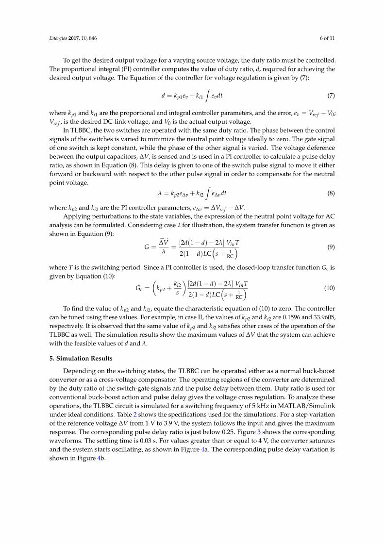
The cross-regulation capabilities of a TLBBC and a three-level boost converter (TLBC) arecompared under the PDC control method. The maximum cross-regulation voltages are calculated forall the 10 cases. The corresponding 3D-plots are shown below. For TLBC, the maximum normalizedcross-regulation voltage is ±0.0625; see Figure 5. For TLBBC, this value is ±0.1467; see Figure 6.It shows that the TL buck-boost converter has better cross-regulation capability compared to the TLboost converter under same cross-voltage regulation method.
The cross-regulation voltage values in the figures below indicate the theoretical maximum foreach duty ratio and pulse delay ratio. However, in practical scenarios, these values can be lower thanthat calculated here. The peracetic drops, the component lead impedances and losses in the switchesand diodes restrict the converter to achieve these peak values. The parameters used for this simulationis also the same as the parameters used for the previous simulations and listed in Table 2.
Energies 2017, 10, 846 7 of 11
Figure 3. Maximum values of (a) capacitor voltage imbalance ∆V, and (b) corresponding pulse delay ratio λ.
Figure 4. Values on controller saturation (a) capacitor voltage difference ∆V, and (b) pulse delay ratio λ.
6. Comparison with Three-Level Boost Converter
The cross-regulation capabilities of a TLBBC and a three-level boost converter (TLBC) are compared under the PDC control method. The maximum cross-regulation voltages are calculated for all the 10 cases. The corresponding 3D-plots are shown below. For TLBC, the maximum normalized cross-regulation voltage is ±0.0625; see Figure 5. For TLBBC, this value is ±0.1467; see Figure 6. It shows that the TL buck-boost converter has better cross-regulation capability compared to the TL boost converter under same cross-voltage regulation method.
The cross-regulation voltage values in the figures below indicate the theoretical maximum for each duty ratio and pulse delay ratio. However, in practical scenarios, these values can be lower than that calculated here. The peracetic drops, the component lead impedances and losses in the switches and diodes restrict the converter to achieve these peak values. The parameters used for this simulation is also the same as the parameters used for the previous simulations and listed in Table 2.
Figure 5. Normalized cross-regulation voltage for three-level boost converter.
Nor
mal
ized
Neu
tral v
olta
ge (V
np,n
orm
)
Figure 5. Normalized cross-regulation voltage for three-level boost converter.
Energies 2017, 10, 846 8 of 11Energies 2017, 10, 846 8 of 11
Figure 6. Normalized cross-regulation voltage for three-level buck-boost converter.
7. Experimental Results
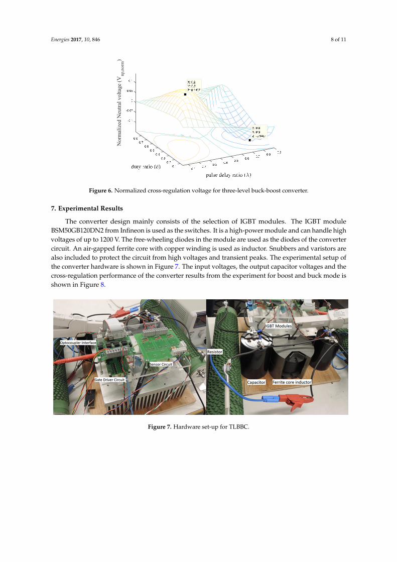
The converter design mainly consists of the selection of IGBT modules. The IGBT module BSM50GB120DN2 from Infineon is used as the switches. It is a high-power module and can handle high voltages of up to 1200 V. The free-wheeling diodes in the module are used as the diodes of the converter circuit. An air-gapped ferrite core with copper winding is used as inductor. Snubbers and varistors are also included to protect the circuit from high voltages and transient peaks. The experimental setup of the converter hardware is shown in Figure 7. The input voltages, the output capacitor voltages and the cross-regulation performance of the converter results from the experiment for boost and buck mode is shown in Figure 8.
Figure 7. Hardware set-up for TLBBC.
Nor
mal
ized
Neu
tral v
olta
ge (V
np,n
orm
)
Figure 6. Normalized cross-regulation voltage for three-level buck-boost converter.
7. Experimental Results
The converter design mainly consists of the selection of IGBT modules. The IGBT moduleBSM50GB120DN2 from Infineon is used as the switches. It is a high-power module and can handle highvoltages of up to 1200 V. The free-wheeling diodes in the module are used as the diodes of the convertercircuit. An air-gapped ferrite core with copper winding is used as inductor. Snubbers and varistors arealso included to protect the circuit from high voltages and transient peaks. The experimental setup ofthe converter hardware is shown in Figure 7. The input voltages, the output capacitor voltages and thecross-regulation performance of the converter results from the experiment for boost and buck mode isshown in Figure 8.
Energies 2017, 10, 846 8 of 11
Figure 6. Normalized cross-regulation voltage for three-level buck-boost converter.
7. Experimental Results
The converter design mainly consists of the selection of IGBT modules. The IGBT module BSM50GB120DN2 from Infineon is used as the switches. It is a high-power module and can handle high voltages of up to 1200 V. The free-wheeling diodes in the module are used as the diodes of the converter circuit. An air-gapped ferrite core with copper winding is used as inductor. Snubbers and varistors are also included to protect the circuit from high voltages and transient peaks. The experimental setup of the converter hardware is shown in Figure 7. The input voltages, the output capacitor voltages and the cross-regulation performance of the converter results from the experiment for boost and buck mode is shown in Figure 8.
Figure 7. Hardware set-up for TLBBC.
Nor
mal
ized
Neu
tral v
olta
ge (V
np,n
orm
)
Figure 7. Hardware set-up for TLBBC.

Energies 2017, 10, 846 9 of 11Energies 2017, 10, 846 9 of 11
Figure 8. Closed loop operation: input and output voltages, capacitor voltages and system response waveforms when (a) d = 0.5, (b) boost mode, d = 0.6, and (c) buck mode, d = 0.4.
In Figure 9, the cross-regulation voltages in calculation, simulation and experiment are compared. The mathematical analysis and simulation results give very similar results while the experimental results are slightly lower. This is due to the losses present in the converter hardware which are not present in the analytical and simulated results assuming ideal conditions.
Figure 9. A comparison of ∆V from analytical, simulation, and experimental results.
8. Conclusions
The three-level buck-boost converter is analyzed to find the amount of cross-regulation it can provide. This analysis is significant for various renewable energy grid integration scenarios where the three-level NPC inverter is used for grid coupling. Varying input from renewable sources imposes high-input cross-regulation requirements for the NPC. A new type of PDC cross-regulation method is proposed to compensate for the imbalance produced at the NPC input. Different operating modes of the TLBBC circuit are analyzed and 10 cases of operation are found, which can be used to control efficiently the maximum possible oprating range of the converter. The expression for the voltage imbalance for each case is formulated using ripple current averaging method. Moreover, the simulation in Matlab/simulink validates the voltage imbalance created in each of these 10 cases. A closed-loop controller using PI controllers is designed based on the operatinal case equations in order
Cro
ss re
gula
atio
n vo
ltage
, V
, (V
)
Figure 8. Closed loop operation: input and output voltages, capacitor voltages and system responsewaveforms when (a) d = 0.5, (b) boost mode, d = 0.6, and (c) buck mode, d = 0.4.
In Figure 9, the cross-regulation voltages in calculation, simulation and experiment are compared.The mathematical analysis and simulation results give very similar results while the experimentalresults are slightly lower. This is due to the losses present in the converter hardware which are notpresent in the analytical and simulated results assuming ideal conditions.
Energies 2017, 10, 846 9 of 11
Figure 8. Closed loop operation: input and output voltages, capacitor voltages and system response waveforms when (a) d = 0.5, (b) boost mode, d = 0.6, and (c) buck mode, d = 0.4.
In Figure 9, the cross-regulation voltages in calculation, simulation and experiment are compared. The mathematical analysis and simulation results give very similar results while the experimental results are slightly lower. This is due to the losses present in the converter hardware which are not present in the analytical and simulated results assuming ideal conditions.
Figure 9. A comparison of ∆V from analytical, simulation, and experimental results.
8. Conclusions
The three-level buck-boost converter is analyzed to find the amount of cross-regulation it can provide. This analysis is significant for various renewable energy grid integration scenarios where the three-level NPC inverter is used for grid coupling. Varying input from renewable sources imposes high-input cross-regulation requirements for the NPC. A new type of PDC cross-regulation method is proposed to compensate for the imbalance produced at the NPC input. Different operating modes of the TLBBC circuit are analyzed and 10 cases of operation are found, which can be used to control efficiently the maximum possible oprating range of the converter. The expression for the voltage imbalance for each case is formulated using ripple current averaging method. Moreover, the simulation in Matlab/simulink validates the voltage imbalance created in each of these 10 cases. A closed-loop controller using PI controllers is designed based on the operatinal case equations in order
Cro
ss re
gula
atio
n vo
ltage
, V
, (V
)
Figure 9. A comparison of ∆V from analytical, simulation, and experimental results.
8. Conclusions
The three-level buck-boost converter is analyzed to find the amount of cross-regulation it canprovide. This analysis is significant for various renewable energy grid integration scenarios where thethree-level NPC inverter is used for grid coupling. Varying input from renewable sources imposeshigh-input cross-regulation requirements for the NPC. A new type of PDC cross-regulation method isproposed to compensate for the imbalance produced at the NPC input. Different operating modesof the TLBBC circuit are analyzed and 10 cases of operation are found, which can be used to controlefficiently the maximum possible oprating range of the converter. The expression for the voltageimbalance for each case is formulated using ripple current averaging method. Moreover, the simulation

Energies 2017, 10, 846 10 of 11
in Matlab/simulink validates the voltage imbalance created in each of these 10 cases. A closed-loopcontroller using PI controllers is designed based on the operatinal case equations in order to achievethe desired voltage compensation. When PDC and convensional duty ratio controls are combined,the converter gives full performance by providing both output voltage control, as well as crossregulation. The cross-regulation capability of the TLBBC converter is compared to the TLBC converterto show its superiority in cross regulation. The simulation results are verified using experimentalresults. The results shows that the TLBBC has a better cross-regulation capability, which can be reallyuseful to support three-level NPC based renewable grid integration. In this study, the input voltagesare considered as equal. However, it would be of interest to see the converter feasibility with unequalinput voltage. This is considered as an area future study.
Acknowledgments: This work is funded by SweGRIDS–Swedish Centre for Smart Grids and Energy Storage.The authors would like to thank European Institute of Innovation and Technology (EIT) KIC InnoEnergy, SwedishEnergy Agency and ‘STandUP for Energy’ for their support.
Author Contributions: First author Deepak Elamalayil Soman has written the paper and performed theexperiments under the supervision of second author Mats Leijon.
Conflicts of Interest: The authors declare no conflict of interest.
References
1. Carrasco, J.M.; Franquelo, L.G.; Bialasiewicz, J.T.; Galvan, E.; Portillo, R.; Prats, M.M.; Leon, J.I.; Moreno, N.Power-Electronic Systems for the Grid Integration of Renewable Energy Sources: A Survey. IEEE Trans. Ind.Electron. 2006, 53, 1002–1016. [CrossRef]
2. Singaravel, M.M.R.; Daniel, S.A. MPPT with Single DC-DC Converter and Inverter for Grid-ConnectedHybrid Wind-Driven PMSG-PV System. IEEE Trans. Ind. Electron. 2015, 62, 4849–4857. [CrossRef]
3. Hartnett, K.J.; Hayes, J.G.; Rylko, M.S.; Barry, B.J.; Maslon, J.W. Comparison of 8-kW CCTT IM and DiscreteInductor Interleaved Boost Converter for Renewable Energy Applications. IEEE Trans. Ind. Appl. 2015, 51,2455–2469. [CrossRef]
4. Yaramasu, V.; Wu, B.; Rivera, M.; Rodriguez, J. A New Power Conversion System for Megawatt PMSG WindTurbines Using Four-Leve Simple Control Scheme Based on Two-Step Model Predictive Strategy—Part I:Modeling and Theoretical Analysis. IEEE J. Emerg. Sel. Top. Power Electron. 2014, 2, 3–13. [CrossRef]
5. Errouissi, R.; Al-Durra, A.; Muyeen, S.M. A Robust Continuous-Time MPC of a DC-DC Boost ConverterInterfaced with a Grid-Connected Photovoltaic System. IEEE J. Photovolt. 2016, 6, 1619–1629. [CrossRef]
6. Das, M.; Agarwal, V. Novel High-Performance Stand-Alone Solar PV System with High-Gain High-EfficiencyDC-DC Converter Power Stages. IEEE Trans. Ind. Appl. 2015, 51, 4718–4728. [CrossRef]
7. Jamshidpour, E.; Poure, P.; Saadate, S. Photovoltaic Systems Reliability Improvement by Real-TimeFPGA-Based Switch Failure Diagnosis and Fault-Tolerant DC-DC Converter. IEEE Trans. Ind. Electron. 2015,62, 7247–7255. [CrossRef]
8. Maity, S.; Sahu, P.K. Modeling and Analysis of a Fast and Robust Module-Integrated Analog PhotovoltaicMPP Tracker. IEEE Trans. Power Electron. 2016, 31, 280–291. [CrossRef]
9. Tan, L.; Wu, B.; Yaramasu, V.; Rivera, S.; Guo, X. Effective Voltage Balance Control for Bipolar-DC-Bus-FedEV Charging Station with Three-Level DC–DC Fast Charger. IEEE Trans. Ind. Electron. 2016, 63, 4031–4041.[CrossRef]
10. Krishna, R.; Kottayil, S.K.; Leijon, M. Predictive Current Controller for a Grid Connected Three Level Inverterwith Reactive Power Control. In Proceedings of the 2010 IEEE 12th Workshop on Control and Modeling forPower Electronics (COMPEL), Boulder, CO, USA, 28–30 June 2010; pp. 1–6.
11. Yaramasu, V.; Wu, B. Predictive Control of a Three-Level Boost Converter and an NPC Inverter forHigh-Power PMSG-Based Medium Voltage Wind Energy Conversion Systems. IEEE Trans. Power Electron.2014, 29, 5308–5322. [CrossRef]
12. Filba-Martinez, A.; Busquets-Monge, S.; Nicolas-Apruzzese, J.; Bordonau, J. Operating Principle andPerformance Optimization of a Three-Level NPC Dual-Active-Bridge DC-DC Converter. IEEE Trans. Ind.Electron. 2016, 63, 678–690. [CrossRef]

Energies 2017, 10, 846 11 of 11
13. Vitoi, L.A.; Krishna, R.; Soman, D.E.; Leijon, M.; Kottayil, S.K. Control and Implementation of Three LevelBoost Converter for Load Voltage Regulation. In Proceedings of the 39th Annual Conference of the IEEEIndustrial Electronics Society (IECON), Vienna, Austria, 10–13 November 2013; pp. 561–565.
14. Krishna, R.; Soman, D.E.; Kottayil, S.K.; Leijon, M. Pulse Delay Control for Capacitor Voltage Balancing ina Three-Level Boost Neutral Point Clamped Inverter. IET Power Electron. 2015, 8, 268–277. [CrossRef]
15. Soman, D.E.; Krishna, R.; Leijon, M.; Vikram, K.; Kottayil, K.; Vitoi, L.A.; Oliveira, J.G.; Kumar, S.S.Discontinuous Conduction Mode of a Three-Level Boost DC-DC Converter and Its Merits and Limitsfor Voltage Cross Regulation Applications. In Proceedings of the 40th Annual Conference of the IEEEIndustrial Electronics Society (IECON), Dalas, TX, USA, 29 October–1 November 2014; pp. 4268–4272.
16. Soman, D.E.; Vikram, K.; Krishna, R.; Gabrysch, M.; Kottayil, S.K.; Leijon, M. Analysis of Three-LevelBuck-Boost Converter Operation for Improved Renewable Energy Conversion and Smart Grid Integration.In Proceedings of the 2014 IEEE International Energy Conference (ENERGYCON), Cavtat, Croatia,13–16 May 2014; pp. 76–81.
17. Davoudi, A.; Jatskevich, J.; Rybel, T.D. Numerical State-Space Average-Value Modeling of PWM DC-DCConverters Operating in DCM and CCM. IEEE Trans. Power Electron. 2016, 21, 1003–1012. [CrossRef]
© 2017 by the authors. Licensee MDPI, Basel, Switzerland. This article is an open accessarticle distributed under the terms and conditions of the Creative Commons Attribution(CC BY) license (http://creativecommons.org/licenses/by/4.0/).