cross laminated timber solutions - woodworks · 2018-12-17 · design aid for clt fire resistance...
TRANSCRIPT

CrossLaminatedTimberSolutions
AddressingCommonDesignChallengesforUseToday

“TheWoodProductsCouncil”isaRegisteredProviderwithTheAmericanInstituteofArchitectsContinuingEducationSystems(AIA/CES),Provider#G516.
Credit(s)earnedoncompletionofthiscoursewillbereportedtoAIACESforAIAmembers.CertificatesofCompletionforbothAIAmembersandnon-AIAmembersareavailableuponrequest.
ThiscourseisregisteredwithAIACESforcontinuingprofessionaleducation.Assuch,itdoesnotincludecontentthatmaybedeemedorconstruedtobeanapprovalorendorsementbytheAIAofanymaterialofconstructionoranymethodormannerofhandling,using,distributing,ordealinginanymaterialorproduct.________________________________Questionsrelatedtospecificmaterials,methods,andserviceswillbeaddressedattheconclusionofthispresentation.
CourseDescription
NowavailabletoNorthAmericanbuildingdesigners,crosslaminatedtimber(CLT)offersthestructuralsimplicityneededforcost-effectiveprojects,aswellasbenefitssuchasfastinstallation,reducedwaste,improvedthermalperformanceanddesignversatility.ThispresentationwillcoversomeofthemorechallengingaspectsofCLTbuildingdesign,includingfireandlifesafety,lateralandseismicdesign,acousticperformanceandbuildingenvelope.Resourcesavailabletodesignandconstructionprofessionals,suchasthenewUSCLTHandbook,willalsobediscussed.

LearningObjectives
1. ReviewanswerstocommonquestionsregardingthedesignandconstructionofCLTstructures,includingthoserelatedtocostanddesigningforexposedconditions.
2. EvaluatethefirecharacteristicsofCLT,includingthebenefitsofcharring,effectsoflamination,flamespreadandmore.
3. DiscusscurrentseismicapproachesthatcanbeusedforCLTbuildingsaswellasthefutureofseismictesting.
4. ConsidertheacousticandmoistureperformanceofCLTassembliesandhowtheyinformthedesignofaproject.

Outline
• CLTDesign• Fire• Lateral• Acoustic• BuildingEnclosure
• Including…..• InformationavailableintheCLTHandbook• Informationfromadditionalresources• AnswerstoFrequentlyAskedQuestions

FireDesign
• FireDesign• BuildingTypes• FireResistance• Connections
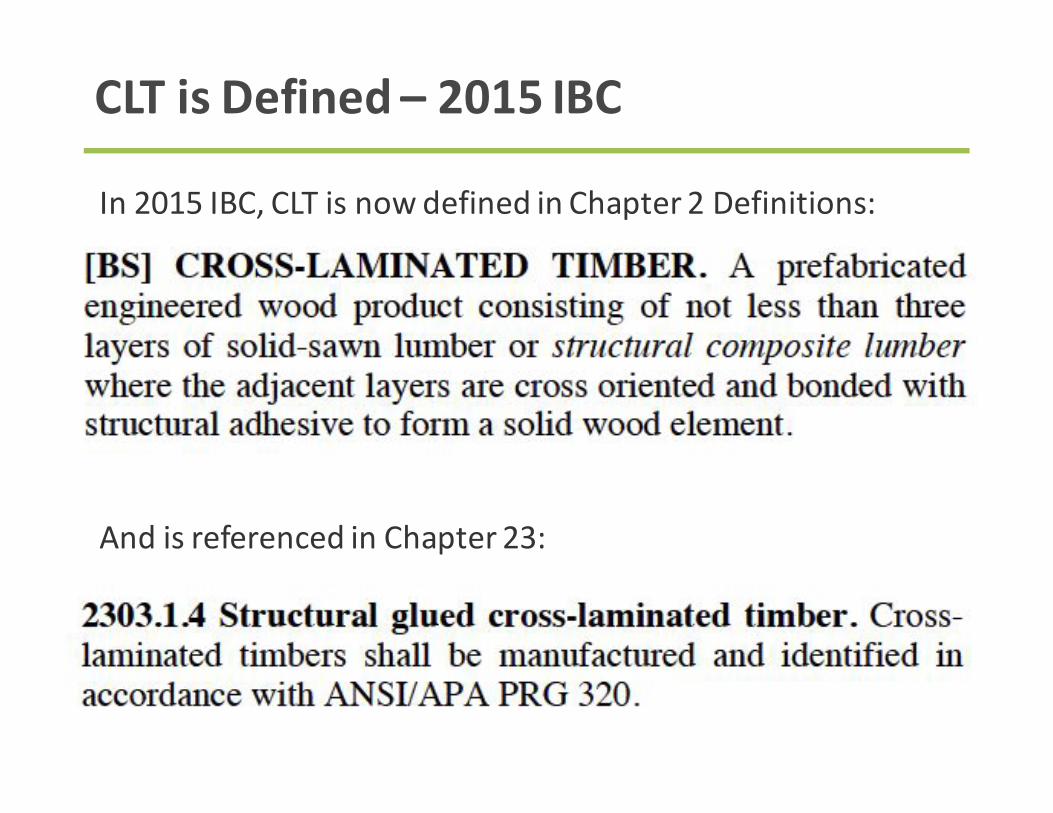
CLTisDefined– 2015IBC
In2015IBC,CLTisnowdefinedinChapter2Definitions:
AndisreferencedinChapter23:

AllowableUsesofCLTinTypesIII,IV,&V
AllowableCLTApplications
PermittedinFloors
PermittedinRoofs
PermittedinInteriorWalls
PermittedinExteriorWalls
TypeIII Yes Yes Yes No
TypeIVa Yes, min.4”
Yes,min.3” Yesb Yesw/coveringc
TypeV Yes Yes Yes Yes
Footnotesa– ConcealedspacesarenotpermittedintypeIVconstructionperIBC2015602.4.6&602.4.7b– InteriorwallsintypeIVconstructionshallmeettheminimumsizesinIBC2015602.4.8.1c– RequiredexteriorcoveringonCLTusedinexteriorwallsisFRTsheathing(15/32”min.),gypsumboard(1/2”min.),oranoncombustiblematerial

Fire&LifeSafety– Bldg Types2012 IBC
• TypeIV– HT:combustibleheavytimberallowedwiththeexceptionoftheexteriorwallsandtherequirementthattherearenoconcealedspaces.
StructuralelementsthatcanbeHT:• Floor• Roof• Interiorwalls

Fire&LifeSafety– Bldg Types2015 IBC
StructuralelementsthatcanbeCLTunder2015IBC:• Floor• Roof• Interiorwalls• Exteriorwalls
• TypeIVaregenerallycombustiblewiththeexceptionoftheexteriorwallsthatcanbeCLTorFRTwhentheratingis2hrorless.

ConcealedSpaceLimitationsonHT
TypeIVConstructionrequiresthatinteriorelementsbewithoutconcealedspaces:• Concealedspacesincludedroppedceilings,attics,
chases,others
Concealedspacerequirementdoesnotapplytoanyotherconstructiontype.IfusingheavytimberelementsinnontypeIVconstruction,concealedspacesarepermittedbutmayberequiredtobesprinklered
Example ofconcealed spacecreatedbydroppedceiling
Source:USCLTHandbook

FireandLifeSafety– BuildingTypes
• TypeIV- FireresistancerequirementsdoNOT applytoHTConstructionexceptattheExteriorWalls
Source2015IBC

FireandLifeSafety– BuildingTypes
BUSINESSBusinessOccupancyNFPA13SprinklersIBC903.3.1.1Modifications6stories85feet135,000sq.ft./floormax(w/frontage)405,000sq.ft.totalmax (w/frontage)NoFirewalls
Source2015IBC

FireandLifeSafety– ConstructionTypeIII
StructuralelementsthatcanbeCLT:• Floor• Roof• Interiorwalls
• TypeIIIisnoncombustibleexteriorandcombustibleinterior.Fire-retardant-treatedwoodframingispermittedintheexteriorwalls.

FireandLifeSafety– ConstructionTypeV
• TypeVaregenerallycombustiblesuchaswoodalthoughVpermitsanymaterialpermittedbycode
AllstructuralelementscanbecombustibleconstructionincludingCLT:• Exteriorwalls• Floor• Roof• Interiorwalls

FireandLifeSafety– BuildingTypes• TypesIIIA&VAare protectedconstructionandrequirea1hrratingforallstructuralelementswithsomeexceptionsforroofs(2hrs forext.wallsintypeIII– CLTcannotbeusedinext.wallsoftypeIII)
• CLTmaybeusedwithcalculatedfireresistanceperNDSChapter16referencedinIBC722.1

FireandLifeSafety– BuildingTypes
• TypesIIIB&VBare unprotectedconstructionandrequiresnofireratingonanybuildingelements.
• UseCLTwithoutrequirementforcalculatedfireresistance(sizeforstructuralloadsonly)
• MinHTSizesinIBC602.4donotneedtobemet

FireResistance- Calculated

TypeIV– HeavyTimber-FireRequirements
InavarietyofwaysthebuildingcodedoesrecognizetheabilityforHeavyTimbertoresistfiresthroughcharring.

CLT’sFireResistanceCapabilities
Similartoheavytimber,CLTasamasstimberproducthasinherentfireresistancecapabilities

NDSChapter16forCLTFireResistance
2015NDSisthe1st EditiontoIncludeCalculationofCLTFireResistance

DesignAidforCLTFireResistance
AWC’sTechnicalReport10includesdiscussionofCLTfiretestsanddesignexamples
Freedownloadatawc.org

FireandLifeSafety– AMMR
IfaprojectisunderIBC2012orolder,AMMRcanbeusedtojustifyCLT’suse
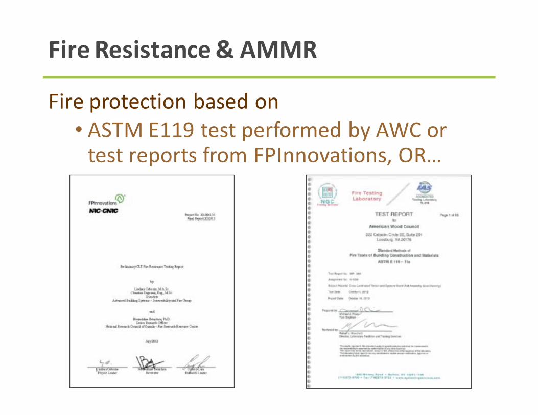
FireResistance&AMMR
Fireprotectionbasedon• ASTME119testperformedbyAWCortestreportsfromFPInnovations,OR…

ASTME119FireResistanceTest
• 5-PlyCLT(6-7/8”thick)• 5/8”TypeXGWBeachside• Goal:Min.2hourfireresistance• RESULTS:3hours6minutes
Freedownloadatawc.org

FullScaleE119Testingwasdonetoprovethecalculationmethods.
Theadvantagetoacalculatedmethodisversatility(notrelyingonassemblyteststoincludeyourexactassembly).
FireResistanceCalculationunderAMMR
http://www.awc.org/Code-Officials/2012-IBC-Challenges/Preliminary-CLT-Fire-Test-Report-FINAL-July2012.pdf

FireProtectionofConnections
Connectionsmustbeappropriatelydesignforstructuralrequirementsand……• Connectionsinprotectedconstructionrequire
protectionalsousingwood,gypsumorotherapprovedmaterial
ConsiderationsofExposedMetalConnectorsinFireSituations:
• Strengthcompromised• Reducedcapacityinheatedzone• Thermalconductivityofconnectoritself
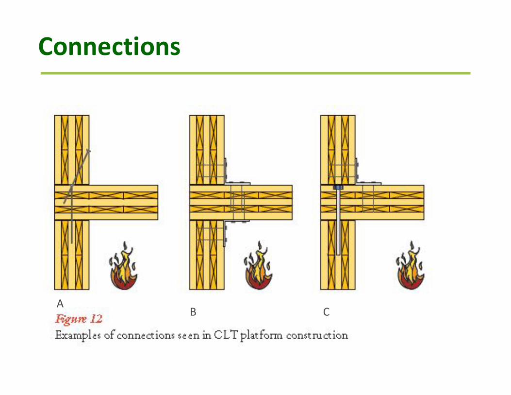
Connections
AB C

Connections

Connections

Connections

Connections
www.awc.org
• Fireratingsforconnectionsareestablishedbythefireratingofthesystem.
• TypeIVConstructionprovidefireresistance,butisnotrated.

InteriorFinishes– ExposedCLT
WoodInteriorFinish– Flamespread• Buildingoccupancy• Locationofthematerialinthebuilding• Sprinklersornosprinklers
ASTME84orUL723TestMethodIBC803.1.1&Table803.11

InteriorFinishes– ExposedCLT

InteriorFinishes– ExposedCLT
Species FlameSpreadIndex
FlameSpreadClass
SmokeDevelopedIndex
Douglas-Fir 70 B 80Hem-fir speciesgroup
60 B 70
Pine,EasternWhite 70 B 110
Pine,SouthernYellow
70 B 165
Spruce,Black (4”thick,3layersofcrosslaminations)
35 B 55
AWC’sDCA1listsFlameSpreadandSmokeDevelopedIndicesforanumberofsoftwoodlumberspecies
http://www.awc.org/pdf/codes-standards/publications/dca/AWC-DCA1-FlameSpreadPerformance-1509.pdf

GravityDesign

ModelBuildingCodeAcceptance
2015International Building Code
2015National DesignSpecification forWoodConstruction (NDS)
ANSI/APAPRG320-2011

CLTProductStandard
ANSI/APAPRG320• CLTStressclasses• QualityAssurancetesting• Identificationmarking

CLTStressGrades
StressGrade MajorStrengthDirection
MinorStrength Direction
E1 1950f-1.7E MSR SPF #3 Spruce Pine Fir
E2 1650f-1.5E MSR DFL #3 Doug Fir Larch
E3 1200f-1.2E MSR Misc #3 Misc
E4 1950f-1.7E MSR SP #3 Southern Pine
V1 #2 Doug Fir Larch #3 Doug Fir Larch
V2 #1/#2 Spruce Pine Fir #3 Spruce Pine Fir
V3 #2 Southern Pine #3 Southern Pine
Non-mandatory in PRG 320. Other stress grades including SCL permitted

Strength
PhotosCourtesyStructurlam

CLTPanelCapacitiesANSI/APAPRG320

CLTPanelCapacitiesfromManufacturer
Source:NordicX-Lam,StressGradeE1
Source:Structurelam,StressGradeV2

NewChapter10 coveringAdjustmentFactorsforCLT
CLTinNDS2015– PanelStrength

Floors&Roofs

Non-homogenous,anisotropicmaterial
StructuralSectionProperties
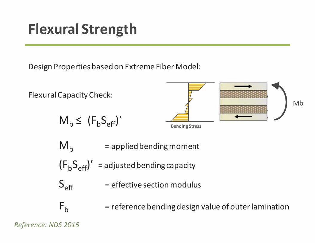
DesignPropertiesbasedonExtremeFiberModel:
FlexuralCapacityCheck:
Mb ≤(FbSeff)′
Mb =appliedbendingmoment
(FbSeff)′ =adjustedbendingcapacity
Seff =effectivesectionmodulus
Fb =referencebendingdesignvalueofouterlamination
FlexuralStrength
Mb
BendingStress
Reference:NDS2015

DesignPropertiesbasedonExtremeFiberModel:
FlexuralCapacityCheck(ASD)
(FbSeff)′ =CD CM Ct CL (FbSeff)
FlexuralStrength
Mb
BendingStress
Commonly1.0
FromManufacturer*
Mb ≤CD (1.0)(FbSeff)
perNDS
Reference:NDS2015&ProductReports

DesignPropertiesbasedonExtremeFiberModel:
ShearCapacityCheck:
Vplanar ≤Fs(Ib/Q)eff′
Vplanar =appliedshear
Fs (IbQeff) ′ =adjustedshearstrength
ShearStrength
Vplanar
ShearStress
Reference:NDS2015&USCLTHandbook

DesignPropertiesbasedonExtremeFiberModel:
ShearCapacityCheck(ASD):
Fs(IbQ)eff′ =CMCt(Fs(IbQ)eff)=CMCtVs
Vplanar ≤(1.0)Vs
ShearStrength
Vplanar
ShearStress
Commonly1.0
FromManufacturerforStandardSections
Reference:NDS2015&USCLTHandbook

Stiffness&Deflection
MajorAxisStiffness
EIeff,0 GAeff,0
MinorAxisStiffness
EIeff,90 GAeff,90

StructuralSectionProperties
Values inRED providedbyCLTmanufacturer
FlexuralStrength: FbSeff,0FlexuralStiffness: EIeff,0ShearStrength: Vs,0ShearStiffness: GAeff,0
FbSeff,90EIeff,90Vs,90GAeff,90
Reference:PRG320andCLTProductReports

Occupantperceptionofvibrationisahighlyrecommendeddesignconsideration.
Oneapproach:CLTHandbook,Chapter7
Calculatednaturalfrequencyofsimplespan:
Where:
EIapp =apparentstiffnessfor1footstrip,pinnedsupported,
uniformly loaded,simplespan(Ks =11.5)(lb-in2)
ρ =specificgravityoftheCLT
A =thecrosssectionarea(thicknessx12inches)(in2)
FloorVibration
Reference:USCLTHandbook,Chapter7

CLTHandbook,Chapter7recommends,
FloorVibration
MaxspanL
and
Reference:USCLTHandbook,Chapter7

CLTFloorPaperAvailable

CLTBearingWallsCLTpanelscanbeusedinbearingwallapplicationsNDSChapter10providesinformationondesignconsiderationsandadjustmentfactors

CLTBearingWalls
TableCourtesyStructurlam

ConnectionDetails
Source:Structurelam

ConnectorsforCLTinNDS2015:
DowelTypeFasteners,e.g.LagScrews,WoodScrewsandNails
UniqueDesignConsiderationsduetoalternatinggraindirection
ConnectorDesigninCLT- NDS2015

WithdrawlLagscrewsloadedinendgraininnarrowedgeofCLT,regardlessofgrainorientation,shallhavetheircapacityreducedbyendgrainfactor=0.75(NDS12.2.1.5)
ConnectorDesigninCLT- NDS2015
Nails,woodscrewsandspikesshallnotbeloadedinwithdrawlinCLTendgrain(NDS12.2.2.4&12.2.3.6)

DowelBearingStrength:
• Panelfacevs.paneledge
ConnectorDesigninCLT- NDS2015

ConnectorDesigninCLT- NDS2015
LateralDesignEndGrainFactor:
D<¼”:Ceg =0.67(ifinendgrainonly)
D>¼”:Ceg =0.67(ifinnarrowfaceregardlessofgraindirection)

DowelBearingLength:
• Adjustedwithgraindirection
ConnectorDesigninCLT- NDS2015

ConnectorDesigninCLT- NDS2015
Example:
½“BoltinSPF3-plyCLTwith1-½“plies
Im =t1II +t2perp +t3II =3(1.5)=4.5”
Im-adj =t1II +t2perp(Feperp/FeII)+t3II=1.5+1.5(2450/3350)+1.5=4.1”

ConnectorDesigninCLT- NDS2015
Enddistance,edgedistanceandfastenerspacingrequirementsinnarrowedge
NDSFigure12I

LateralDesign

CLTSeismicForceResistingSystemsNotRecognizedIn
CLTSeismicDesign
ASCE/SEI7-10 SDPWS2015

CLTPanelscanbeusedasstructuraldiaphragmsandshearwallsprovidedAMMRprocessisutilized.Testingisunderwaytoestablishdesignvalues
CLTinLateralForceResistingSystems
Source:ACeccottiintheUSCLTHandbook

PanelIn-PlaneStrength:• Panelstrengthgenerallydon’tgoverndiaphragmshearstrength.• ReferenceDesignValues
• Not coveredbyAPAPRG320productstandard• ArecoveredbyNewICCAC455AcceptanceCriteria• AskfordesignvaluesfromtheManufacturers
ConnectionStrength:• Commodityconnectors(e.g.Nails)perNDS2015• ProprietaryConnectors(Self-TappingScrews)perEvaluationReports,Manufacturer’sInformationandEngineeringMechanics.
• Forseismicdesign,selectconnectiondetailssoductilelimitstatesgoverncapacities.
CLTFloorsasDiaphragms

NewChapter10 coveringAdjustmentFactorsforCLT
FormattingSimilartoWoodStructuralPanels
CLTinNDS2015– PanelStrength

ANSI/APAPRG320ProductReports
DoesnotincludeIn-planePanel ShearStrength

ICC-ESAcceptanceCriteriaAC455
DefinesIn-planePanel ShearStrengthTestforuseinFloorandRoofDecks

CLTPanelshaveaveryhighin-planeshearstrength.
CLTinLateralForceResistingSystems
Source:TheCrossLaminatedTimberDesignGuide fromStructurlam

CLTinLateralForceResistingSystems
Source:NordicCLTGuide

SimilartoWoodStructuralPanelShearWalls
ConnectionsDetermineLateralStrength
Lightframeshearwallstrength isdependent onperimeter (edge)nailing
Source:SDPWS2008

FloorPaneltoFloorPanel
ConnectionStyles
InteriorSpline
SingleSurfaceSpline
DoubleSurfaceSpline
HalfLap

ConnectionStyles

SimilartoWoodStructuralPanelShearWalls
ConnectionsDetermineLateralStrength
CLTShearStrengthDepends onConnections
Source:USCLTHandbook

ConnectionDetails
Simpleconnectionswith:- Metalangles- SelftappingScrews
Source:USCLTHandbook Source:Structurelam

ConnectionDetails
Source:Nordic

FastenersandBrackets

ConnectionPublishedCapacities

OverturningRestraintConnections
Source:TimberConnect
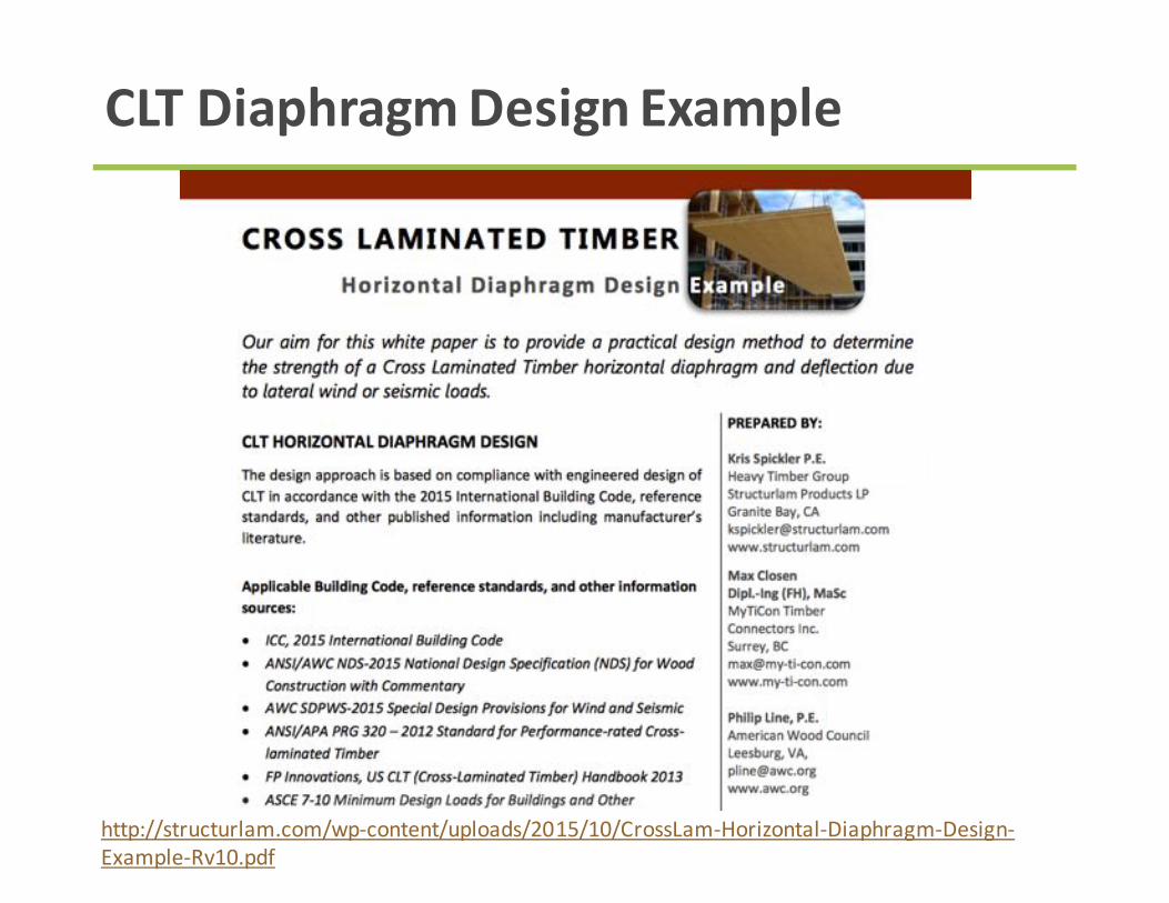
CLTDiaphragmDesignExample
http://structurlam.com/wp-content/uploads/2015/10/CrossLam-Horizontal-Diaphragm-Design-Example-Rv10.pdf

• DevelopmentofseismicparametersforEquivalentLinearForceundercurrentresearchviaFEMAP-695process
• Innovativehighperformancesystemsundercurrentresearch.
• Forthenearterm,CLTshearwallsystemspossiblyjustifiedviaalternativemeans:
• ConservativeSeismicDesignParameters• Performance-BasedDesignleveraging
researchornewtesting
CLTasaSeismicLFRSSummary

• PossibleroutesforneartermseismicdiaphragmdesignsunderAlternativeMeansandMethodsinclude
1)ElasticDesignMethod• Basedonlower-boundstrengthofcomponents• FollowingnewASCE7-16alternativediaphragm
methodtodetermineelasticseismicdiaphragmforcedemands
2)Capacity-BasedDesignMethod• Usingdesignatedyieldingconnectionswith
overstrengthdesignofnon-desirablelimitstates.
• Basedonyieldingconnectiontechnologiesofprovencyclicbehavior§ RelativelyequivalenttoWoodStructuralPanel
diaphragmbehaviorOR§ AdvancedEngineeringwithsupportingtestingto
justifydesign
IdeasforNearTermSeismicProjects

CLTDiaphragmScenarios
CLTShearWalls
CLTPanelDiaphragm
LargeDiaphragmSpans…Withmultiplepanelsperspan
ChordsandCollectors
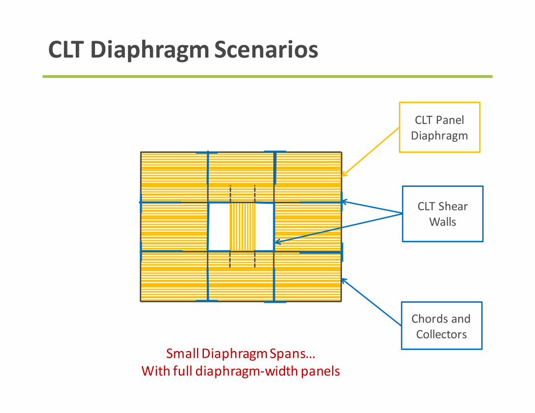
CLTDiaphragmScenarios
CLTShearWalls
CLTPanelDiaphragm
SmallDiaphragmSpans…Withfulldiaphragm-widthpanels
ChordsandCollectors

CLTDiaphragmScenarios
BRBFrames
CLTPanelDiaphragm
DiaphragmspanningbetweenSoftBraces
ChordsandCollectors

CLTDiaphragmScenarios
ConcreteShearWall
Core
CLTPanelDiaphragm
DiaphragmcantileveringoffStiffCore
ChordsandCollectors

CLTDiaphragmScenarios
Realbuildingsarenotallrectangles
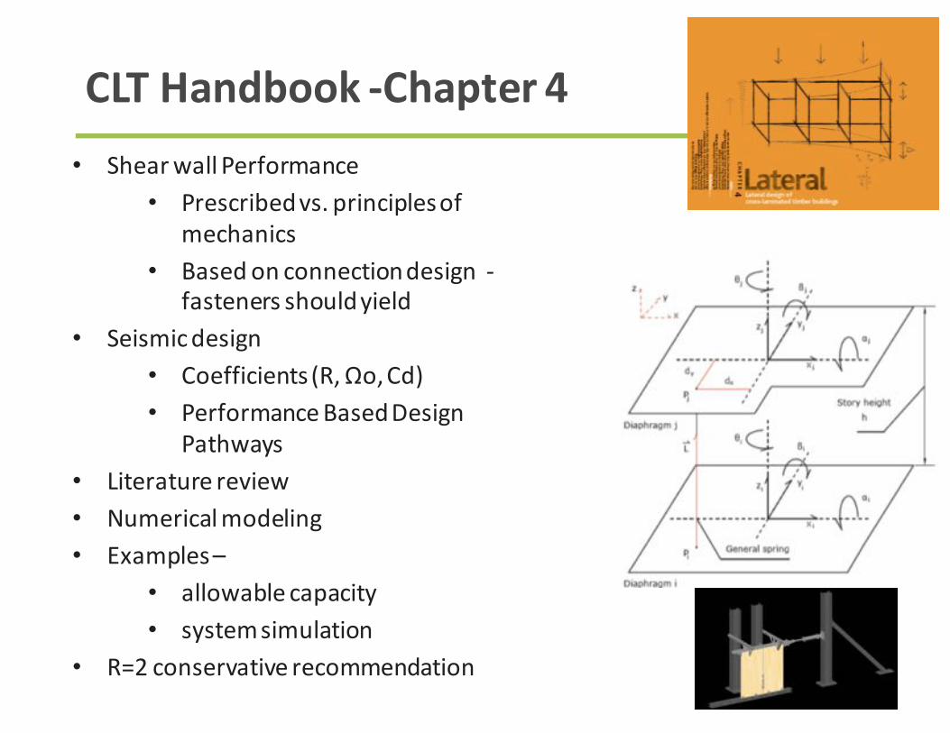
CLTHandbook-Chapter4• ShearwallPerformance
• Prescribedvs.principlesofmechanics
• Basedonconnectiondesign-fastenersshouldyield
• Seismicdesign• Coefficients(R,Ωo,Cd)• PerformanceBasedDesign
Pathways• Literaturereview• Numericalmodeling• Examples–
• allowablecapacity• systemsimulation
• R=2conservativerecommendation

AcousticDesign
Acoustics– NonHTsystems
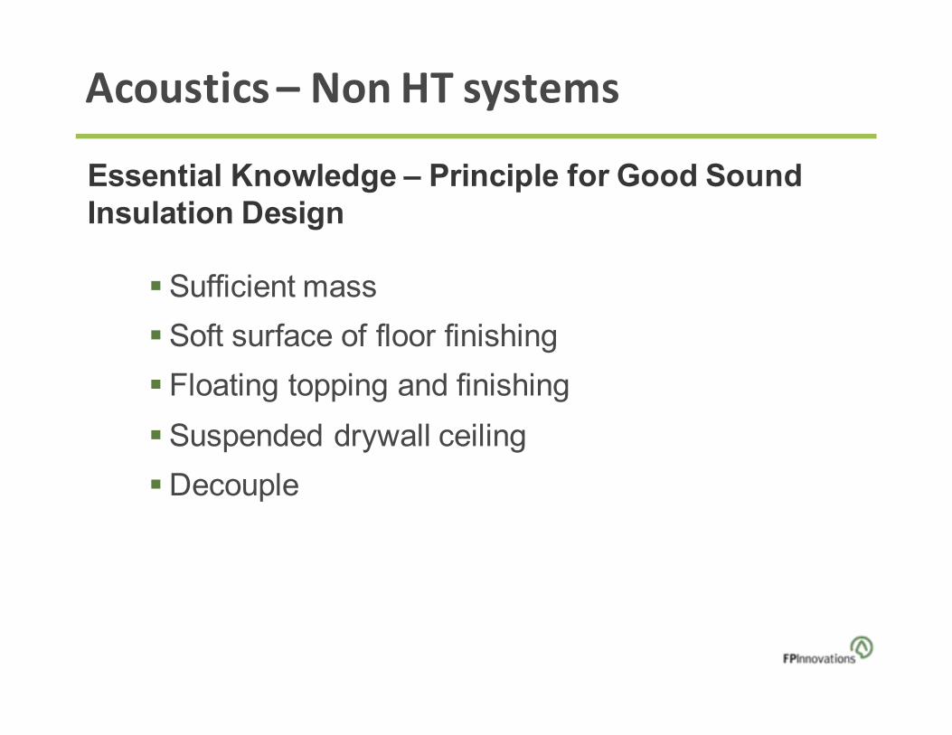
Essential Knowledge – Principle for Good SoundInsulation Design
§ Sufficient mass
§ Soft surface of floor finishing
§ Floating topping and finishing
§ Suspended drywall ceiling
§ Decouple

Acoustics
Perceivable sound pressure differential
is 3dB
Important rule for the development of cost-effective solutions!

Acoustics
Number of layers Thickness (in. ) Assembly type STC IIC
3 3-3/4 to 4-1/2 Wall 32-34 N.A.
5 5-1/3 Floor 39 23
5 5-3/4 Floor 39 24
Measuredon field bare CLT wall and floor
Number of layers Thickness in. Assembly type FSTC FIIC
3 4-1/8 Wall 28 N.A.
7 8-1/5 Floor N.A 25-30
Sound Insulation of Bare CLT Floors and Walls

Acoustics– NonHTSystems
- STC 50:1 and 3 = 4-1/2 in. CLT; 2=1-1/8 in. Mineral wool in the gap
- STC 55:Adding 5/8 in. gypsum board directly to both sides
- STC 60:with the gypsum boards and double the thickness of the gap
and mineral wool
- STC 58:1 and 7 = 5/8 in. gypsum boards3 and 5 = 2 in. by 3 in. wood studs at least 16 in. o.c.2 and 6 = 2.5 in. mineral wool 4 = 4-1/2 in. CLT
Design Examples for >50 STC Walls

Acoustics
Top view of cross-section Wall detail FSTC1 & 5 = 5/8” Gypsum board
2 & 4 = Resilient channels at24” o.c.
3. 5-layer CLT of 7-1/4”
46
1 & 7 = 5/8” Gypsum board
2 & 6 = Resilient channels at 24” o.c
3 & 5 = 3-layer CLT of 3.07”
4 = 1” air gap filled with mineral wool
47
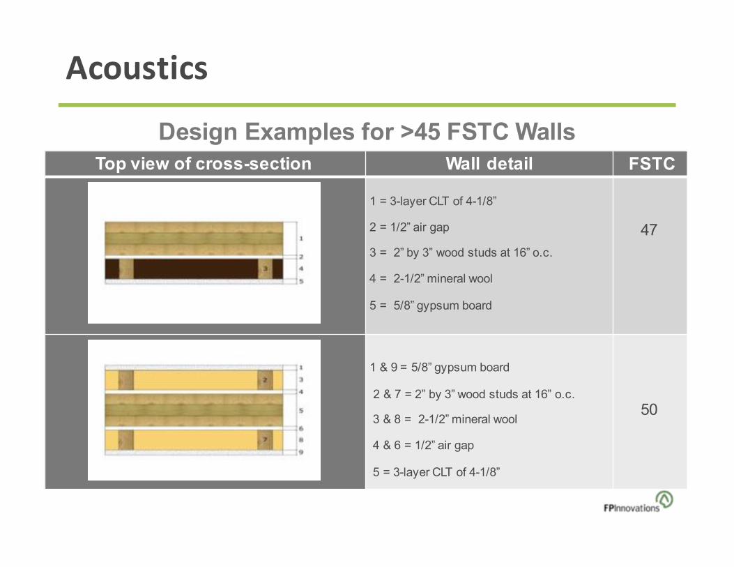
Design Examples for >45 FSTC Walls
Acoustics
FSTC
1 = 3-layer CLT of 4-1/8”
2 = 1/2” air gap
3 = 2” by 3” wood studs at 16” o.c.
4 = 2-1/2” mineral wool
5 = 5/8” gypsum board
47
1 & 9 = 5/8” gypsum board
2 & 7 = 2” by 3” wood studs at 16” o.c.
3 & 8 = 2-1/2” mineral wool
4 & 6 = 1/2” air gap
5 = 3-layer CLT of 4-1/8”
50
Design Examples for >45 FSTC WallsTop view of cross-section Wall detail

Acoustics
Design Examples for >45 FSTC and FIIC FloorsEnd view of cross-section Floor detail FSTC FIIC
1 = Carpet, or floating flooring about 2/5” on 1/8” resilient underlayment of 0.16 to0.37 lb./ft.2
2 = At least 5.12 lb./ft.2 dry topping, e.g. 0.8-1” gypsum board, cement fibreboard
3 = Resilient underlayment, e.g. 2/5” rubber mat of 0.84 lb./ft.2 , ¾” texture felt of 0.27 lb./ft.2 , ½” low density wood fibreboard of 0.73lb./ft.2
4 = 5-layer CLT of 6-7/8”
~45 ~45
- Replace the dry topping by wet topping,e.g. 1.5” concrete of at least 15.6 lb./ft.2 ~50 ~50

Acoustics
FIIC
1 = Carpet, or flooring about 2/5”
2 = 1/8” resilient underlayment of 0.16 to 0.37 lb./ft.2
3 = 5-layer CLT of 6-7/8”
4 = Sound Isolation Clips of 4” high
5 = Metal hat channel at 16” o.c.
6 = Sound absorption material (such as glass fibre) of 4”
7 = Gypsum board of 5/8”
8 = Gypsum boardof 5/8”
~50 ~50
- Replace 1) by hardwood flooring nailed to ¾” plywood
- Replace 2) by thick resilient underlayment, e.g. 2/5” rubber mat of 0.84 lb./ft.2 , ¾” texture felt of 0.27 lb./ft.2 ,½” low-density wood fibre board of 0.73 lb./ft.2
~53 ~53
- Replace 1) by ceramic tile glued to ½” and ¾” plywood
- Replace 2) by thick resilient underlayment, e.g. 2/5” rubber mat of 0.84 lb./ft.2 , ¾” texture felt of 0.27 lb./ft.2 ,½” low-density wood fibreboard of 0.73lb./ft.2
~53 ~53
Design Examples for >45 FSTC and FIIC FloorsEnd view of cross-section Floor detail FSTC

Chapter9- Sound
• AcousticpropertiesofCLT• STCandIICratedassemblies• FSTCandFIICratedassemblies• RecommendationsformeetingIBCrequirements

FrequentlyAskedQuestion:
1. Arethereanysubstitutionsformorecommonacousticassemblymaterials?
Fermacellcanbereplacedwithcement–fiberboardaslongasithasthesameorhigherdensity(32kg/m2).
IsoverisverysimilartoRoxul(Rockwool).
yes

FrequentlyAskedQuestion:
1. Aretheremoretestedassembliesavailable?
NRChasdataonassembliesbeyondthoseintheHandbook
Additionalassembliesmaybetested
Acousticianscanestimatesoundperformancebasedonsoundtestdata
yes

BuildingEnclosureDesign

Building Enclosure Design
• CLTwallassembliesshouldbebuilt“breathable”
• Preventraininfiltrations
• Wettingduringtransportation,constructionandserviceshouldbeminimized
• Studiesshowthatinheatingclimatethatnovaporbarrierwillberequiredatinterior

MoistureManagement
• Rainscreen• cavitydirectlybehindthe
cladding• allowsimproveddrying• Openingsincladdingattop
andbottom• Drainedwall
• RequiresWRB• 1/16”airgapsuggested• Drainagewraprecommended
withfoaminsulation• ORgrovescutinbacksideof
foaminsulation

MoistureManagement
• WaterResistiveBarrier• Essentialpart• Properlyoverlappedina
shinglefashion• integratewithflashings• Sealedatallpenetrations

EnergyPerformance
ExteriorInsulation• Providescontinuity(nobreakatfloors)• ShieldsCLTandairbarrierfromtemp
(lessexpansionandcontraction)• Capitalizesmorethermalmassbenefit• Keepsitwarmer(incoldclimates)• Lowerssurfacerelativehumidity• Keepsitdryer(inhothumid)

Energy Performance
Rigidshearblocktypeconnectionthroughinsulation,claddingtoverticalstrapping

Energy Performance
Air-tightasamaterial,butnotasasystemRecommend• self-adhered sheetproductair
barriermembranes• orthickliquidappliedmembrane
onexteriorofpanels(exteriorair-barrierapproach)
Notrecommended• loose-appliedsheets(House-
wraps)

Energy Performance
Sealants,tapes,&membranesappliedoneithersidecan’taddressthistypeofairflowpaththroughtheCLTlumbergaps
Airflowpathmoreconvoluted– lowerleakagerates,butstillaconsideration

RoofAssemblies

RoofAssemblies

CLTHandbook-Chapter10
• PropertiesofCLT• Watervaporabsorption• Permeability• Liquidwaterabsorption• Heatstorage/transfer• Airpermeability
• Approachestoexteriorwatermanagement
• RecommendedAssemblies• MoistureControlDuring
Construction• PreservativeTreatment

Resources
2x6studwall Double-studwall 2x4(or2x6)studwall CLT/masstimber 2x4(or2x6)studwall
Interior-insulatedwallassemblies Exterior-insulatedwallassemblies Split-insulatedwallassembly
http://www.fpinnovations.ca/ResearchProgram/AdvancedBuildingSystem/designing-energy-efficient-building-enclosures.pdf
BuildingsinMarinetoColdClimateZonesinNorthAmerica

Resources
Woodframing
Exteriorinsulation[R-value/inch(RSI/cm)]
Exteriorinsulationthickness3inchesR-value(RSI)]
4inches[R-value(RSI)]
5inches[R-value(RSI)]
6inches[R-value(RSI)]
7inches[R-value(RSI)]
8inches[R-value(RSI)]
3½-inch-thickCLTpanels
R-4/inch(0.28/cm)
17.2(3.0)
20.9(3.7)
24.4(4.3)
27.9(4.9)
31.6(5.6)
35.0(6.2)
R-5/inch(0.34/cm)
19.8(3.5)
24.4(4.3)
28.7(5.1)
32.9(5.8)
37.3(6.6)
41.5(7.3)
Chapter4– EnergyEfficientWallsExteriorInsulated• Materialselection&
guidance• ControlFunctions• CriticalBarriers• EffectiveR-valueTables
BuildingsinMarinetoColdClimateZonesinNorthAmerica

WoodWorks –PortaltoCLTInformation

Questions?
EthanMartin,[email protected](206)[email protected]
ThisconcludesTheAmericanInstituteofArchitectsContinuingEducationSystemsCourse

ThispresentationisprotectedbyUSandInternationalCopyrightlaws.
Reproduction,distribution,displayanduseofthepresentationwithoutwrittenpermission
ofthespeakerisprohibited.
©TheWoodProductsCouncil2016
CopyrightMaterials