cross coupling reactions in organic synthesis themed … · this article was published as part of...
TRANSCRIPT
This article was published as part of the
Cross coupling reactions in organic synthesis themed issue
Guest editor: Matthias Beller
All authors contributed to this issue in honour of the 2010 Nobel Prize
in Chemistry winners, Professors Richard F. Heck, Ei-ichi Negishi and Akira Suzuki
Please take a look at the issue 10 2011 table of contents to
access other reviews in this themed issue
Publ
ishe
d on
08
Aug
ust 2
011.
Dow
nloa
ded
by U
nive
rsite
de
Mon
trea
l on
24/1
1/20
14 2
1:40
:38.
View Article Online / Journal Homepage / Table of Contents for this issue
5010 Chem. Soc. Rev., 2011, 40, 5010–5029 This journal is c The Royal Society of Chemistry 2011
Cite this: Chem. Soc. Rev., 2011, 40, 5010–5029
Cross-coupling in floww
Timothy Noel* and Stephen L. Buchwald*
Received 22nd March 2011
DOI: 10.1039/c1cs15075h
Until recently, cross-coupling reactions have been exclusively performed in batch processes.
With the advent of microfluidics, significant effort has been devoted to develop a wide variety of
continuous-flow techniques to facilitate organic synthesis. In this critical review, we attempt to
give an overview of the different continuous-flow methodologies that have been developed and
utilized for cross-coupling reactions. In addition, we attempt to point out the advantages of
continuous-flow when compared with their batch counterparts (246 references).
1. Introduction
Since the early 1970s,1–3 cross-coupling chemistry has received
significant attention.4,5 These transformations allow for the
substitution of an aryl, vinyl and alkyl halide/pseudohalide by
a nucleophile in the presence of a transition-metal catalyst.
Typically, the mechanism of cross-coupling reactions is
comprised of 3 steps: (i) oxidative addition, (ii) transmetallation
and (iii) reductive elimination. Most commonly, these reac-
tions involve the formation of a carbon–carbon bond utilizing
a range of different carbon nucleophiles, such as, aryl, vinyl
and alkyl derivatives of magnesium (Kumada–Corriu),1,2 bor-
on (Suzuki–Miyaura),6,7 zinc (Negishi),8,9 silicon (Hiyama),10
tin (Stille-Migita-Kosugi).11–14 More recently, the field of
cross-coupling has been broadened to include carbon–
heteroatom bond forming reactions; the most important of
these involve the construction of C–N,15–17 C–O18,19 and C–S
bonds.20,21
The significance of cross-coupling reaction can hardly be
overestimated. These methods have impacted the pharma-
ceutical and other industries, as well as the synthesis of natural
products and other biologically active molecules.22 Moreover,
they facilitate construction of building blocks for supra-
molecular chemistry, organic materials and polymers.23–25
The development of metal-catalyzed cross-coupling reactions
continues to progress dramatically. Notable examples are the
development of more active palladium catalysts which allow
for lower catalyst loadings,26–33 the development of ‘green’
cross-coupling reactions, which involve the use of first-row
Department of Chemistry, Massachusetts Institute of Technology,77 Massachusetts Avenue, Cambridge, MA 02139, USA.E-mail: [email protected], [email protected];Web: http://mit.edu/chemistry/buchwald/; Fax: +1-617-253-3297;Tel: +1-617-253-1885w Part of a themed issue on the topic of palladium-catalysed crosscouplings in organic synthesis in honour of the 2010 Nobel Prizewinners Professors Richard F. Heck, Ei-ichi Negishi and AkiraSuzuki.
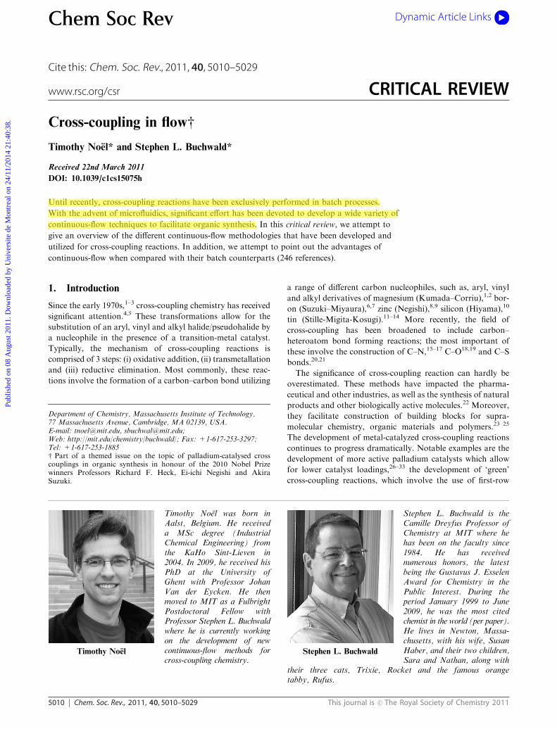
Timothy Noel
Timothy Noel was born inAalst, Belgium. He receiveda MSc degree (IndustrialChemical Engineering) fromthe KaHo Sint-Lieven in2004. In 2009, he received hisPhD at the University ofGhent with Professor JohanVan der Eycken. He thenmoved to MIT as a FulbrightPostdoctoral Fellow withProfessor Stephen L. Buchwaldwhere he is currently workingon the development of newcontinuous-flow methods forcross-coupling chemistry.
Stephen L. Buchwald
Stephen L. Buchwald is theCamille Dreyfus Professor ofChemistry at MIT where hehas been on the faculty since1984. He has receivednumerous honors, the latestbeing the Gustavus J. EsselenAward for Chemistry in thePublic Interest. During theperiod January 1999 to June2009, he was the most citedchemist in the world (per paper).He lives in Newton, Massa-chusetts, with his wife, SusanHaber, and their two children,Sara and Nathan, along with
their three cats, Trixie, Rocket and the famous orangetabby, Rufus.
Chem Soc Rev Dynamic Article Links
www.rsc.org/csr CRITICAL REVIEW
Publ
ishe
d on
08
Aug
ust 2
011.
Dow
nloa
ded
by U
nive
rsite
de
Mon
trea
l on
24/1
1/20
14 2
1:40
:38.
View Article Online
This journal is c The Royal Society of Chemistry 2011 Chem. Soc. Rev., 2011, 40, 5010–5029 5011
transition metals34–37 and the use of water38–42 or ionic
liquids43–44 as a reaction medium, and the employment of
microwave technology for reaction rate acceleration.45–48
In the last decade, continuous-flow microreactors have
emerged as a new tool for both synthetic and process
chemists.49–83 These microreactors provide several advantages
compared to traditional batch reactors. For example,
enhanced heat- and mass-transfer characteristics, safety of
operation when using highly exothermic, explosive or toxic
reagents, precise control over residence (reaction) time,
isolation of sensitive reactions from air and moisture, high
surface-to-volume ratio, the possibility of automation and the
ease of scale-up or operating several devices in parallel
(numbering up). In addition, these microreactors allow for
integration of several reaction steps and subsequent separa-
tions in one single streamlined process, which results in a
significant time-gain compared to traditional batch processes.
As a consequence of these advantages, the use of contin-
uous-flow reactors has attracted a considerable amount of
interest from the pharmaceutical industry.84,85 Currently, the
pharmaceutical industry employs a batch-based manufactur-
ing system, which is costly and time inefficient. Moreover,
typical batch processes are carried out at different locations of
a pharmaceutical plant resulting into many interruptions and
requiring larger production facilities. In times of increasing
environmental awareness and industrial efficiency, the imple-
mentation of continuous-flow technology is becoming a point
of emphasis for many pharmaceutical companies.
Due to the significance of cross-coupling reactions for the
development of new drugs and materials, many methods have
been developed to perform these reactions under continuous-
flow conditions. It is the goal of this review to discuss the
different continuous-flow methodologies that have been utilized
in cross-coupling reactions and to illustrate the power of
continuous processing compared to the traditional batch model.
2. C–C bond formation in flow
2.1 Suzuki–Miyaura cross-coupling reactions in flow
The Suzuki–Miyaura cross-coupling reaction (SMC) can be
regarded as one of the most important methods for the
construction of carbon–carbon bonds.29,86–88 The SMC
protocol allows for the coupling of aryl, vinyl and alkyl
halides/pseudo halides with organoboron compounds
(Scheme 1). The latter are very convenient coupling partners
due to their stability to heat, oxygen, and water, as well as
their commercial availability.89
Many studies have been focused on the development of
heterogeneous catalysts for cross-coupling reactions.90–92 Catalyst
immobilization is of significant importance for flow chemistry
applications (see recent review by Frost and Mutton)59 and holds
promise because of the simplicity of catalyst recovery and
reuse.93 In addition, typical packed bed reactors provide a large
amount of catalyst, which can accelerate the rate of reaction
significantly. Hence, a broad range of solid supports were
developed and applied in SMC flow chemistry, such as, silica,94
monolithic supports,95–104 polymer beads105 and PdEnCatt.106,107
These packed bed reactors showed increased yield with less
by-products compared to the corresponding batch reactions.
However, strong evidence indicates that these solid supports
function as ‘palladium reservoir’ and gradually leach the
catalytically active Pd species into solution.108–115 Further-
more, swelling of the polymer supports, deposition of
products/by-products and the necessity to periodically replace
the cartridges can complicate their use in continuous-flow
chemistry.
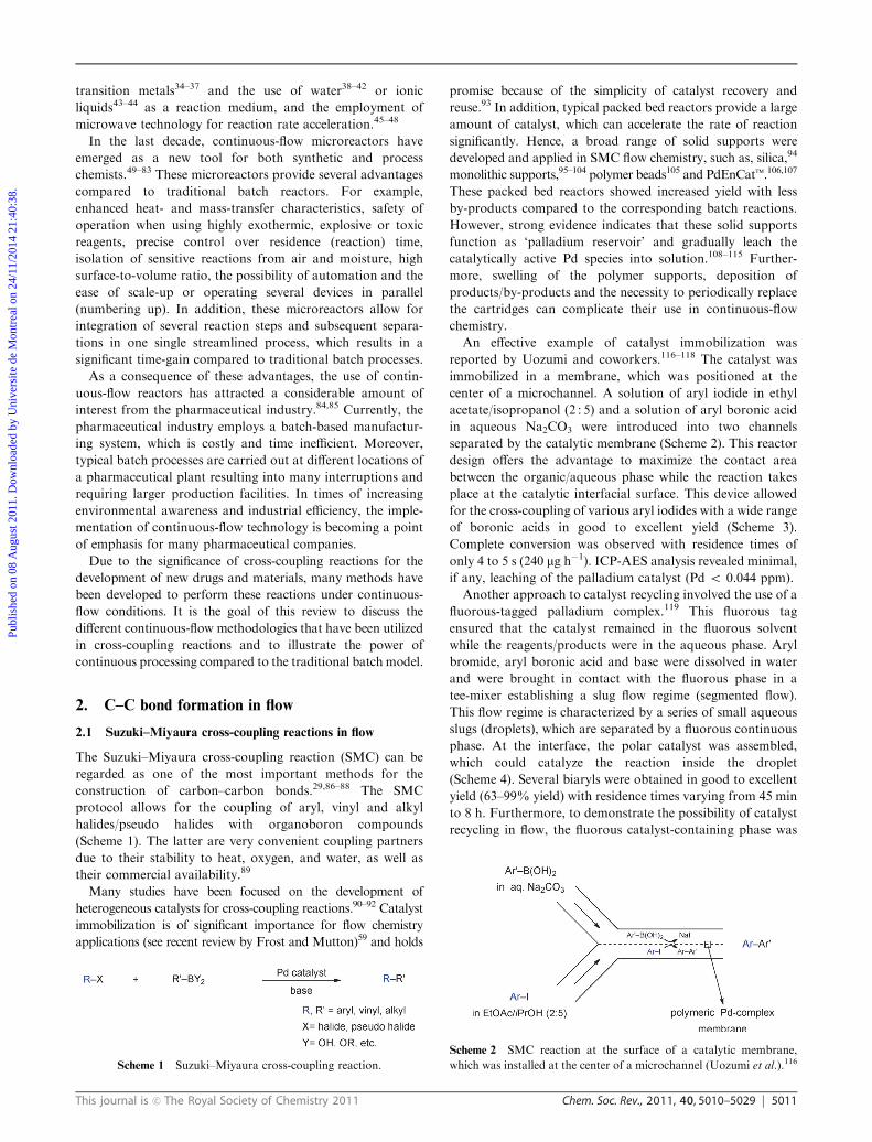
An effective example of catalyst immobilization was
reported by Uozumi and coworkers.116–118 The catalyst was
immobilized in a membrane, which was positioned at the
center of a microchannel. A solution of aryl iodide in ethyl
acetate/isopropanol (2 : 5) and a solution of aryl boronic acid
in aqueous Na2CO3 were introduced into two channels
separated by the catalytic membrane (Scheme 2). This reactor
design offers the advantage to maximize the contact area
between the organic/aqueous phase while the reaction takes
place at the catalytic interfacial surface. This device allowed
for the cross-coupling of various aryl iodides with a wide range
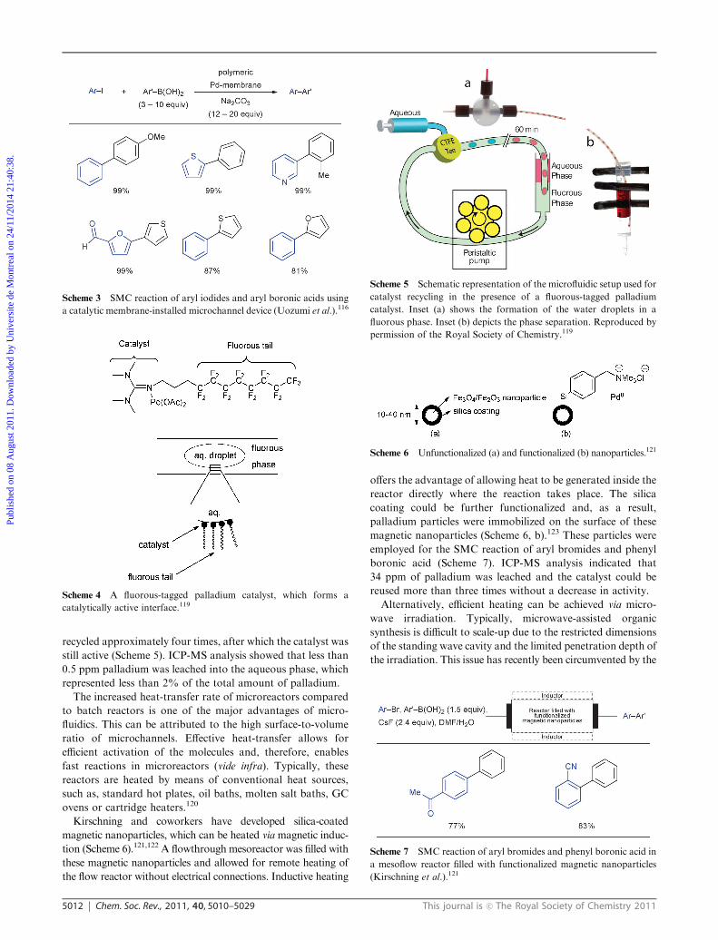
of boronic acids in good to excellent yield (Scheme 3).
Complete conversion was observed with residence times of
only 4 to 5 s (240 mg h�1). ICP-AES analysis revealed minimal,
if any, leaching of the palladium catalyst (Pd o 0.044 ppm).
Another approach to catalyst recycling involved the use of a
fluorous-tagged palladium complex.119 This fluorous tag
ensured that the catalyst remained in the fluorous solvent
while the reagents/products were in the aqueous phase. Aryl
bromide, aryl boronic acid and base were dissolved in water
and were brought in contact with the fluorous phase in a
tee-mixer establishing a slug flow regime (segmented flow).
This flow regime is characterized by a series of small aqueous
slugs (droplets), which are separated by a fluorous continuous
phase. At the interface, the polar catalyst was assembled,
which could catalyze the reaction inside the droplet
(Scheme 4). Several biaryls were obtained in good to excellent
yield (63–99% yield) with residence times varying from 45 min
to 8 h. Furthermore, to demonstrate the possibility of catalyst
recycling in flow, the fluorous catalyst-containing phase was
Scheme 1 Suzuki–Miyaura cross-coupling reaction.
Scheme 2 SMC reaction at the surface of a catalytic membrane,
which was installed at the center of a microchannel (Uozumi et al.).116
Publ
ishe
d on
08
Aug
ust 2
011.
Dow
nloa
ded
by U
nive
rsite
de
Mon
trea
l on
24/1
1/20
14 2
1:40
:38.
View Article Online
5012 Chem. Soc. Rev., 2011, 40, 5010–5029 This journal is c The Royal Society of Chemistry 2011
recycled approximately four times, after which the catalyst was
still active (Scheme 5). ICP-MS analysis showed that less than
0.5 ppm palladium was leached into the aqueous phase, which
represented less than 2% of the total amount of palladium.
The increased heat-transfer rate of microreactors compared
to batch reactors is one of the major advantages of micro-
fluidics. This can be attributed to the high surface-to-volume
ratio of microchannels. Effective heat-transfer allows for
efficient activation of the molecules and, therefore, enables
fast reactions in microreactors (vide infra). Typically, these
reactors are heated by means of conventional heat sources,
such as, standard hot plates, oil baths, molten salt baths, GC
ovens or cartridge heaters.120
Kirschning and coworkers have developed silica-coated
magnetic nanoparticles, which can be heated viamagnetic induc-
tion (Scheme 6).121,122 A flowthrough mesoreactor was filled with
these magnetic nanoparticles and allowed for remote heating of
the flow reactor without electrical connections. Inductive heating
offers the advantage of allowing heat to be generated inside the
reactor directly where the reaction takes place. The silica
coating could be further functionalized and, as a result,
palladium particles were immobilized on the surface of these
magnetic nanoparticles (Scheme 6, b).123 These particles were
employed for the SMC reaction of aryl bromides and phenyl
boronic acid (Scheme 7). ICP-MS analysis indicated that
34 ppm of palladium was leached and the catalyst could be
reused more than three times without a decrease in activity.
Alternatively, efficient heating can be achieved via micro-
wave irradiation. Typically, microwave-assisted organic
synthesis is difficult to scale-up due to the restricted dimensions
of the standing wave cavity and the limited penetration depth of
the irradiation. This issue has recently been circumvented by the
Scheme 3 SMC reaction of aryl iodides and aryl boronic acids using
a catalytic membrane-installed microchannel device (Uozumi et al.).116
Scheme 4 A fluorous-tagged palladium catalyst, which forms a
catalytically active interface.119
Scheme 5 Schematic representation of the microfluidic setup used for
catalyst recycling in the presence of a fluorous-tagged palladium
catalyst. Inset (a) shows the formation of the water droplets in a
fluorous phase. Inset (b) depicts the phase separation. Reproduced by
permission of the Royal Society of Chemistry.119
Scheme 6 Unfunctionalized (a) and functionalized (b) nanoparticles.121
Scheme 7 SMC reaction of aryl bromides and phenyl boronic acid in
a mesoflow reactor filled with functionalized magnetic nanoparticles
(Kirschning et al.).121
Publ
ishe
d on
08
Aug
ust 2
011.
Dow
nloa
ded
by U
nive
rsite
de
Mon
trea
l on
24/1
1/20
14 2
1:40
:38.
View Article Online
This journal is c The Royal Society of Chemistry 2011 Chem. Soc. Rev., 2011, 40, 5010–5029 5013
emergence of continuous-flow methodologies.124,125 One of
the first examples of microwave-assisted continuous-flow
organic synthesis was described by Haswell and coworkers.126,127
This method involved coating of the reactor with a gold film,
which led to a more efficient absorption of the microwaves and
enabled the microwave power to be reduced to less than
100 W. The necessity to employ a gold-coated reactor indi-
cates that the microwave irradiation heated the reactor and
not directly the solvent. As a proof of concept, several aryl
halides were coupled with phenyl boronic acid in the presence
of a heterogeneous Pd/Al2O3 catalyst.
Organ developed a microwave-assisted capillary-based flow
system and demonstrated its utility in SMC reactions
(Scheme 8).128,129 The use of capillaries coated with a thin
film of palladium and the utilization of microwave heating
(up to 225 1C) allowed for the efficient coupling of aryl
bromides with aryl boronic acids (Scheme 9). ICP-AES
analysis of the crude cross-coupling product showed that some
of the palladium had leached (19.2 ppm). When the reaction
was repeated in an oil bath in the absence of microwave
irradiation, a much lower conversion was observed. Recently,
Organ, Li and coworkers discovered that, by using a high
definition IR camera, much higher temperatures (700–950 1C)
were obtained in thin-film coated capillaries than was
originally reported. It was speculated that the reaction
conditions are similar to the conditions obtained in flash
vacuum thermolysis.130
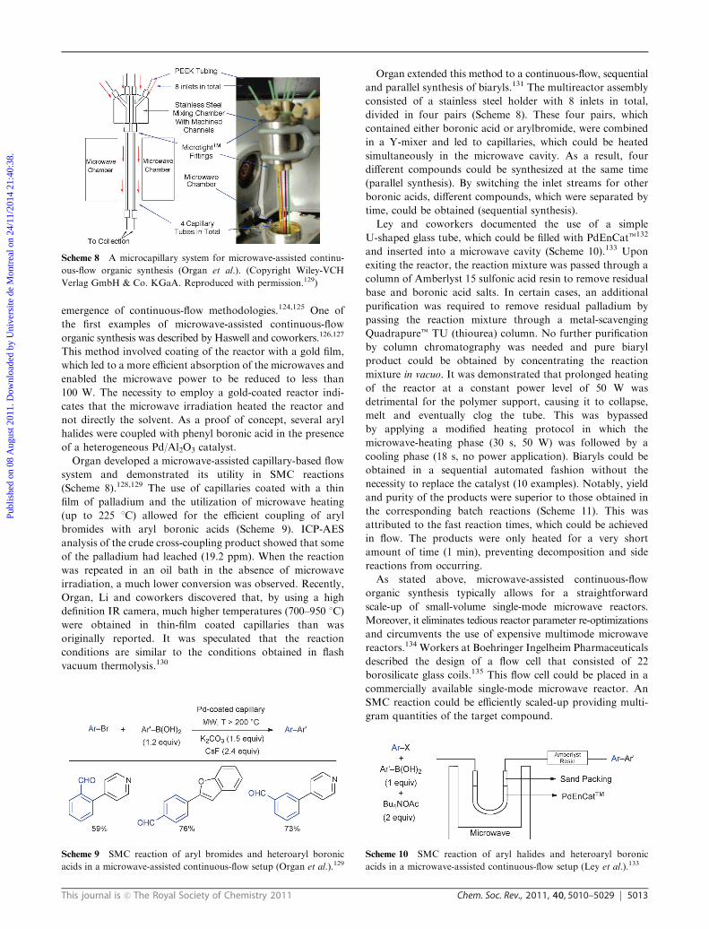
Organ extended this method to a continuous-flow, sequential
and parallel synthesis of biaryls.131 The multireactor assembly
consisted of a stainless steel holder with 8 inlets in total,
divided in four pairs (Scheme 8). These four pairs, which
contained either boronic acid or arylbromide, were combined
in a Y-mixer and led to capillaries, which could be heated
simultaneously in the microwave cavity. As a result, four
different compounds could be synthesized at the same time
(parallel synthesis). By switching the inlet streams for other
boronic acids, different compounds, which were separated by
time, could be obtained (sequential synthesis).
Ley and coworkers documented the use of a simple
U-shaped glass tube, which could be filled with PdEnCatt132
and inserted into a microwave cavity (Scheme 10).133 Upon
exiting the reactor, the reaction mixture was passed through a
column of Amberlyst 15 sulfonic acid resin to remove residual
base and boronic acid salts. In certain cases, an additional
purification was required to remove residual palladium by
passing the reaction mixture through a metal-scavenging
Quadrapuret TU (thiourea) column. No further purification
by column chromatography was needed and pure biaryl
product could be obtained by concentrating the reaction
mixture in vacuo. It was demonstrated that prolonged heating
of the reactor at a constant power level of 50 W was
detrimental for the polymer support, causing it to collapse,
melt and eventually clog the tube. This was bypassed
by applying a modified heating protocol in which the
microwave-heating phase (30 s, 50 W) was followed by a
cooling phase (18 s, no power application). Biaryls could be
obtained in a sequential automated fashion without the
necessity to replace the catalyst (10 examples). Notably, yield
and purity of the products were superior to those obtained in
the corresponding batch reactions (Scheme 11). This was
attributed to the fast reaction times, which could be achieved
in flow. The products were only heated for a very short
amount of time (1 min), preventing decomposition and side
reactions from occurring.
As stated above, microwave-assisted continuous-flow
organic synthesis typically allows for a straightforward
scale-up of small-volume single-mode microwave reactors.
Moreover, it eliminates tedious reactor parameter re-optimizations
and circumvents the use of expensive multimode microwave
reactors.134 Workers at Boehringer Ingelheim Pharmaceuticals
described the design of a flow cell that consisted of 22
borosilicate glass coils.135 This flow cell could be placed in a
commercially available single-mode microwave reactor. An
SMC reaction could be efficiently scaled-up providing multi-
gram quantities of the target compound.
Scheme 8 A microcapillary system for microwave-assisted continu-
ous-flow organic synthesis (Organ et al.). (Copyright Wiley-VCH
Verlag GmbH & Co. KGaA. Reproduced with permission.129)
Scheme 9 SMC reaction of aryl bromides and heteroaryl boronic
acids in a microwave-assisted continuous-flow setup (Organ et al.).129Scheme 10 SMC reaction of aryl halides and heteroaryl boronic
acids in a microwave-assisted continuous-flow setup (Ley et al.).133
Publ
ishe
d on
08
Aug
ust 2
011.
Dow
nloa
ded
by U
nive
rsite
de
Mon
trea
l on
24/1
1/20
14 2
1:40
:38.
View Article Online
5014 Chem. Soc. Rev., 2011, 40, 5010–5029 This journal is c The Royal Society of Chemistry 2011
Researchers at GlaxoSmithKline demonstrated that the
SMC reaction conditions could be optimized in 500 mL slugs
using a design of experiments methodology (DoE).136 These
slugs were separated from each other with a fluorous solvent
as spacer that enabled the use of small reaction volumes and
avoided carry-over from one reaction slug to another. As a
result, these slugs can be regarded as small independent
microreactors. The reaction conditions, optimized for smaller
slugs, could be easily translated to larger slugs (scale-up).
The use of continuous-flow reactors for multistep syntheses
allows for the integration of individual reaction steps in one
single streamlined process without the need to isolate the
intermediates.56 However, continuous-flow multi-step organic
syntheses are extremely challenging since excess reagents and
impurities formed during the reaction must be effectively
removed or must be compatible with the downstream
reactions. To this end, several unit operations have been
developed in order to achieve separations and purifications
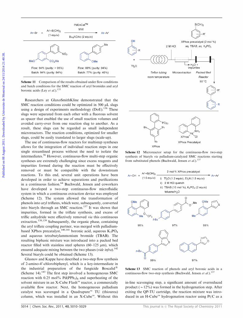
in a continuous fashion.64 Buchwald, Jensen and coworkers
have developed a two-step continuous-flow microfluidic
system in which a continuous extraction device was employed
(Scheme 12). The system allowed the transformation of
phenols into aryl triflates, which were, subsequently, converted
into biaryls through an SMC reaction.137 It was shown that
impurities, formed in the triflate synthesis, and excess of
triflic anhydride were effectively removed via this continuous
extraction.138,139 Subsequently, the organic phase, containing
the aryl triflate coupling partner, was merged with palladium-
based XPhos precatalyst,140,141 boronic acid, aqueous K3PO4
and aqueous tetrabutylammonium bromide (TBAB). The
resulting biphasic mixture was introduced into a packed bed
reactor filled with stainless steel spheres (60–125 mm), which
ensured adequate mixing between the two phases (vide infra).142
Several biaryls could be obtained (Scheme 13).
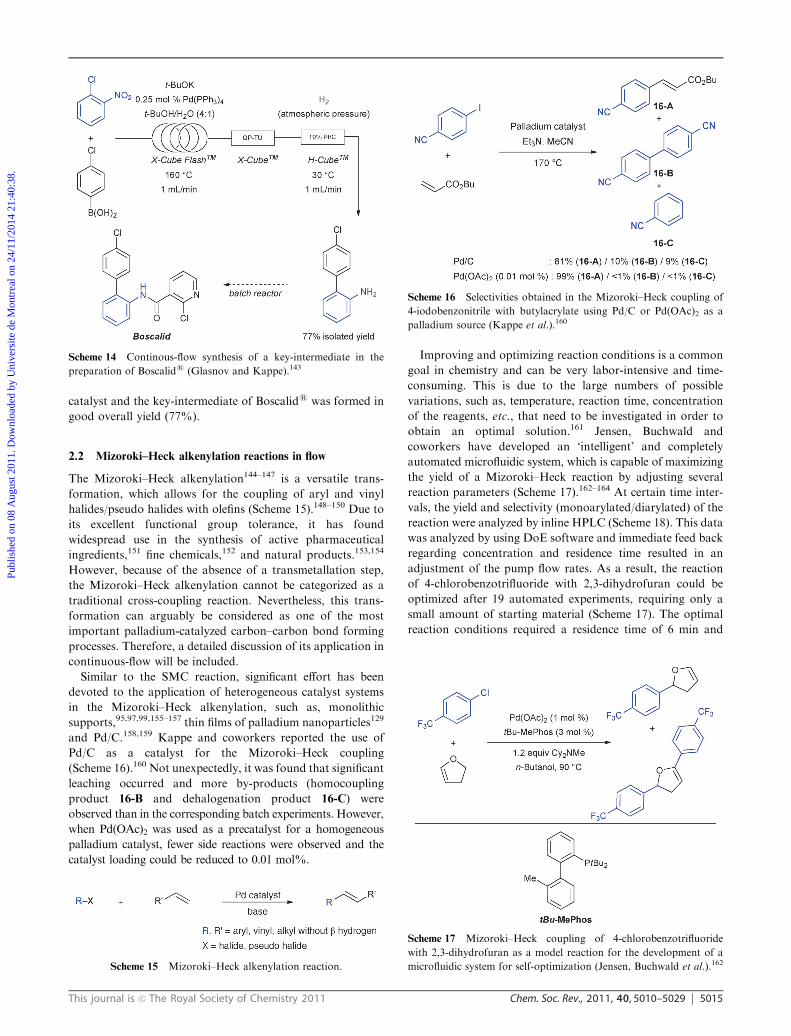
Glasnov and Kappe have described a two-step flow synthesis
of 2-amino-40-chlorobiphenyl, which is a key-intermediate in
the industrial preparation of the fungicide Boscalids
(Scheme 14).143 The first step involved a homogeneous SMC
reaction with 0.25 mol% Pd(PPh3)4 and superheating of the
solvent mixture in an X-Cube Flasht reactor, a commercially
available flow reactor. Next, the homogeneous palladium
catalyst was scavenged in a Quadrapuret TU (thiourea)
column, which was installed in an X-Cubet. Without this
in-line scavenging step, a significant amount of overreduced
product (B12%) was formed in the hydrogenation step. After
exiting the QP-TU cartridge, the reaction mixture was intro-
duced in an H-Cubet hydrogenation reactor using Pt/C as a
Scheme 11 Comparison of the results obtained under flow conditions
and batch conditions for the SMC reaction of aryl bromides and aryl
boronic acids (Ley et al.).133
Scheme 12 Microreactor setup for the continuous-flow two-step
synthesis of biaryls via palladium-catalyzed SMC reactions starting
from substituted phenols (Buchwald, Jensen et al.).137
Scheme 13 SMC reaction of phenols and aryl boronic acids in a
continuous-flow two-step synthesis (Buchwald, Jensen et al.).137
Publ
ishe
d on
08
Aug
ust 2
011.
Dow
nloa
ded
by U
nive
rsite
de
Mon
trea
l on
24/1
1/20
14 2
1:40
:38.
View Article Online
This journal is c The Royal Society of Chemistry 2011 Chem. Soc. Rev., 2011, 40, 5010–5029 5015
catalyst and the key-intermediate of Boscalids was formed in
good overall yield (77%).
2.2 Mizoroki–Heck alkenylation reactions in flow
The Mizoroki–Heck alkenylation144–147 is a versatile trans-
formation, which allows for the coupling of aryl and vinyl
halides/pseudo halides with olefins (Scheme 15).148–150 Due to
its excellent functional group tolerance, it has found
widespread use in the synthesis of active pharmaceutical
ingredients,151 fine chemicals,152 and natural products.153,154
However, because of the absence of a transmetallation step,
the Mizoroki–Heck alkenylation cannot be categorized as a
traditional cross-coupling reaction. Nevertheless, this trans-
formation can arguably be considered as one of the most
important palladium-catalyzed carbon–carbon bond forming
processes. Therefore, a detailed discussion of its application in
continuous-flow will be included.
Similar to the SMC reaction, significant effort has been
devoted to the application of heterogeneous catalyst systems
in the Mizoroki–Heck alkenylation, such as, monolithic
supports,95,97,99,155–157 thin films of palladium nanoparticles129
and Pd/C.158,159 Kappe and coworkers reported the use of
Pd/C as a catalyst for the Mizoroki–Heck coupling
(Scheme 16).160 Not unexpectedly, it was found that significant
leaching occurred and more by-products (homocoupling
product 16-B and dehalogenation product 16-C) were
observed than in the corresponding batch experiments. However,
when Pd(OAc)2 was used as a precatalyst for a homogeneous
palladium catalyst, fewer side reactions were observed and the
catalyst loading could be reduced to 0.01 mol%.
Improving and optimizing reaction conditions is a common
goal in chemistry and can be very labor-intensive and time-
consuming. This is due to the large numbers of possible
variations, such as, temperature, reaction time, concentration
of the reagents, etc., that need to be investigated in order to
obtain an optimal solution.161 Jensen, Buchwald and
coworkers have developed an ‘intelligent’ and completely
automated microfluidic system, which is capable of maximizing
the yield of a Mizoroki–Heck reaction by adjusting several
reaction parameters (Scheme 17).162–164 At certain time inter-
vals, the yield and selectivity (monoarylated/diarylated) of the
reaction were analyzed by inline HPLC (Scheme 18). This data
was analyzed by using DoE software and immediate feed back
regarding concentration and residence time resulted in an
adjustment of the pump flow rates. As a result, the reaction
of 4-chlorobenzotrifluoride with 2,3-dihydrofuran could be
optimized after 19 automated experiments, requiring only a
small amount of starting material (Scheme 17). The optimal
reaction conditions required a residence time of 6 min and
Scheme 14 Continous-flow synthesis of a key-intermediate in the
preparation of Boscalids (Glasnov and Kappe).143
Scheme 15 Mizoroki–Heck alkenylation reaction.
Scheme 16 Selectivities obtained in the Mizoroki–Heck coupling of
4-iodobenzonitrile with butylacrylate using Pd/C or Pd(OAc)2 as a
palladium source (Kappe et al.).160
Scheme 17 Mizoroki–Heck coupling of 4-chlorobenzotrifluoride
with 2,3-dihydrofuran as a model reaction for the development of a
microfluidic system for self-optimization (Jensen, Buchwald et al.).162
Publ
ishe
d on
08
Aug
ust 2
011.
Dow
nloa
ded
by U
nive
rsite
de
Mon
trea
l on
24/1
1/20
14 2
1:40
:38.
View Article Online
5016 Chem. Soc. Rev., 2011, 40, 5010–5029 This journal is c The Royal Society of Chemistry 2011
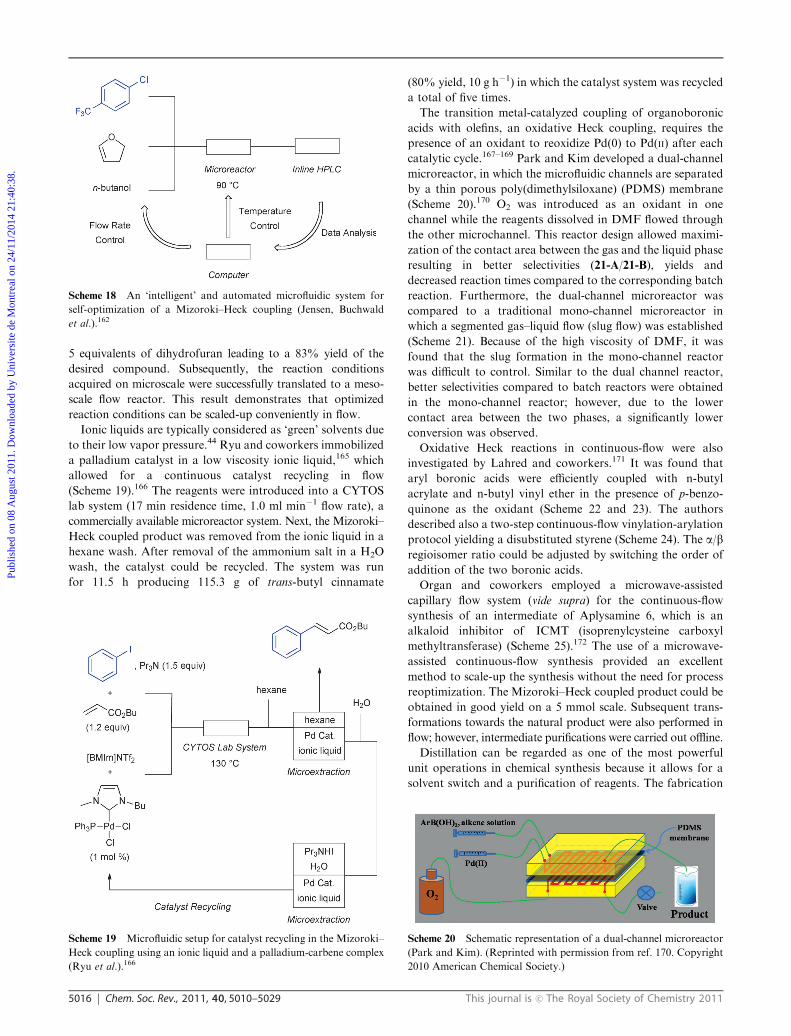
5 equivalents of dihydrofuran leading to a 83% yield of the
desired compound. Subsequently, the reaction conditions
acquired on microscale were successfully translated to a meso-
scale flow reactor. This result demonstrates that optimized
reaction conditions can be scaled-up conveniently in flow.
Ionic liquids are typically considered as ‘green’ solvents due
to their low vapor pressure.44 Ryu and coworkers immobilized
a palladium catalyst in a low viscosity ionic liquid,165 which
allowed for a continuous catalyst recycling in flow
(Scheme 19).166 The reagents were introduced into a CYTOS
lab system (17 min residence time, 1.0 ml min�1 flow rate), a
commercially available microreactor system. Next, the Mizoroki–
Heck coupled product was removed from the ionic liquid in a
hexane wash. After removal of the ammonium salt in a H2O
wash, the catalyst could be recycled. The system was run
for 11.5 h producing 115.3 g of trans-butyl cinnamate
(80% yield, 10 g h�1) in which the catalyst system was recycled
a total of five times.
The transition metal-catalyzed coupling of organoboronic
acids with olefins, an oxidative Heck coupling, requires the
presence of an oxidant to reoxidize Pd(0) to Pd(II) after each
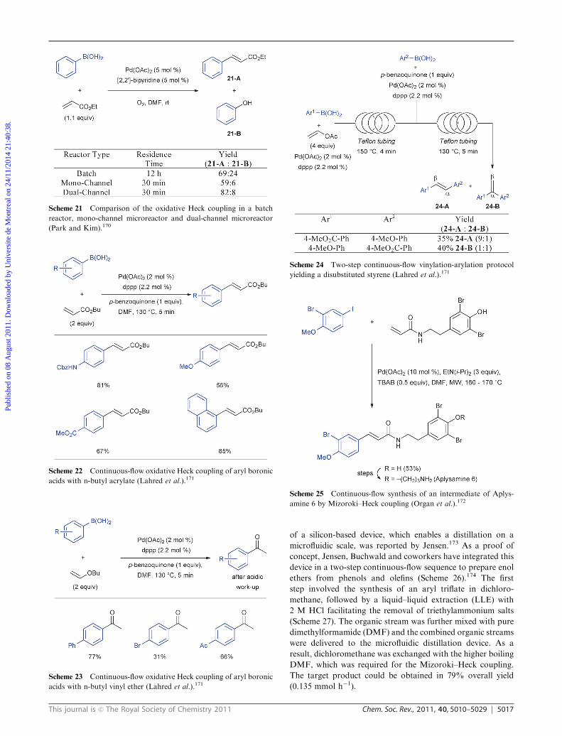
catalytic cycle.167–169 Park and Kim developed a dual-channel
microreactor, in which the microfluidic channels are separated
by a thin porous poly(dimethylsiloxane) (PDMS) membrane
(Scheme 20).170 O2 was introduced as an oxidant in one
channel while the reagents dissolved in DMF flowed through
the other microchannel. This reactor design allowed maximi-
zation of the contact area between the gas and the liquid phase
resulting in better selectivities (21-A/21-B), yields and
decreased reaction times compared to the corresponding batch
reaction. Furthermore, the dual-channel microreactor was
compared to a traditional mono-channel microreactor in
which a segmented gas–liquid flow (slug flow) was established
(Scheme 21). Because of the high viscosity of DMF, it was
found that the slug formation in the mono-channel reactor
was difficult to control. Similar to the dual channel reactor,
better selectivities compared to batch reactors were obtained
in the mono-channel reactor; however, due to the lower
contact area between the two phases, a significantly lower
conversion was observed.
Oxidative Heck reactions in continuous-flow were also
investigated by Lahred and coworkers.171 It was found that
aryl boronic acids were efficiently coupled with n-butyl
acrylate and n-butyl vinyl ether in the presence of p-benzo-
quinone as the oxidant (Scheme 22 and 23). The authors
described also a two-step continuous-flow vinylation-arylation
protocol yielding a disubstituted styrene (Scheme 24). The a/bregioisomer ratio could be adjusted by switching the order of
addition of the two boronic acids.
Organ and coworkers employed a microwave-assisted
capillary flow system (vide supra) for the continuous-flow
synthesis of an intermediate of Aplysamine 6, which is an
alkaloid inhibitor of ICMT (isoprenylcysteine carboxyl
methyltransferase) (Scheme 25).172 The use of a microwave-
assisted continuous-flow synthesis provided an excellent
method to scale-up the synthesis without the need for process
reoptimization. The Mizoroki–Heck coupled product could be
obtained in good yield on a 5 mmol scale. Subsequent trans-
formations towards the natural product were also performed in
flow; however, intermediate purifications were carried out offline.
Distillation can be regarded as one of the most powerful
unit operations in chemical synthesis because it allows for a
solvent switch and a purification of reagents. The fabrication
Scheme 18 An ‘intelligent’ and automated microfluidic system for
self-optimization of a Mizoroki–Heck coupling (Jensen, Buchwald
et al.).162
Scheme 19 Microfluidic setup for catalyst recycling in the Mizoroki–
Heck coupling using an ionic liquid and a palladium-carbene complex
(Ryu et al.).166
Scheme 20 Schematic representation of a dual-channel microreactor
(Park and Kim). (Reprinted with permission from ref. 170. Copyright
2010 American Chemical Society.)
Publ
ishe
d on
08
Aug
ust 2
011.
Dow
nloa
ded
by U
nive
rsite
de
Mon
trea
l on
24/1
1/20
14 2
1:40
:38.
View Article Online
This journal is c The Royal Society of Chemistry 2011 Chem. Soc. Rev., 2011, 40, 5010–5029 5017
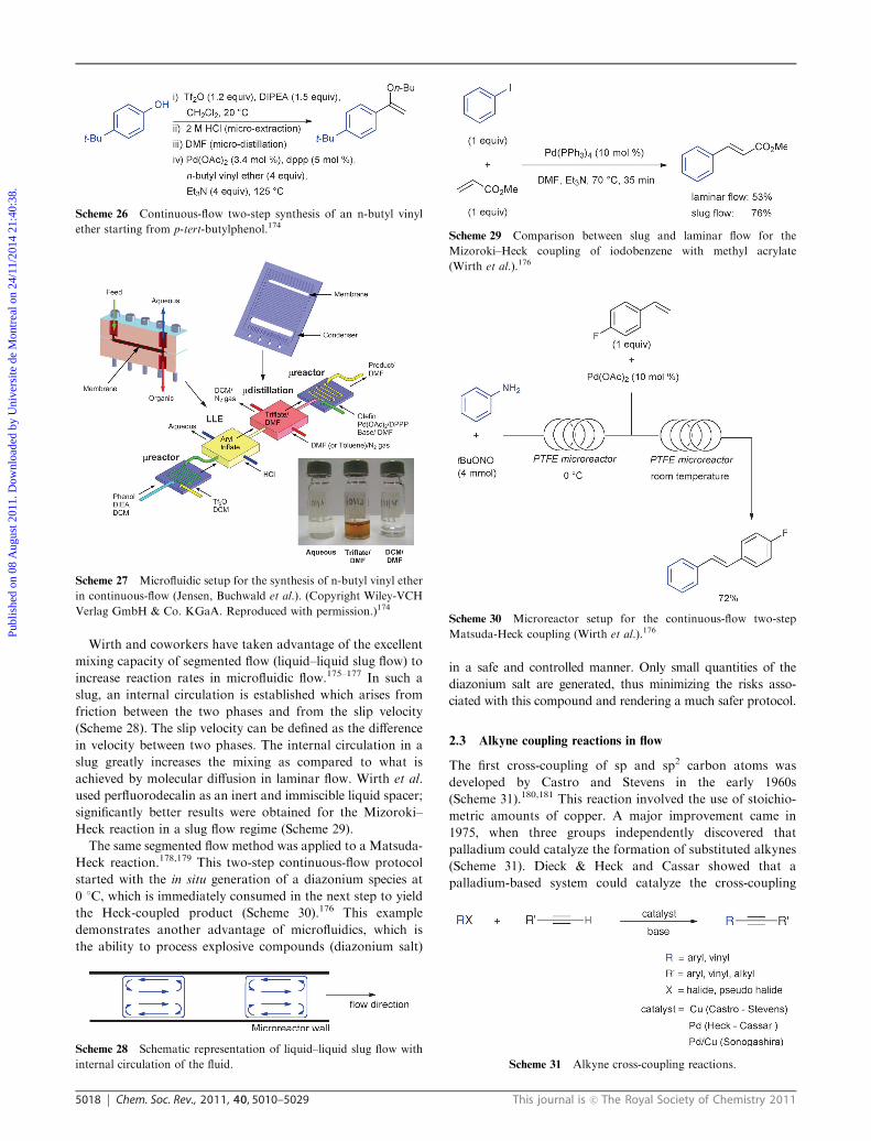
of a silicon-based device, which enables a distillation on a
microfluidic scale, was reported by Jensen.173 As a proof of
concept, Jensen, Buchwald and coworkers have integrated this
device in a two-step continuous-flow sequence to prepare enol
ethers from phenols and olefins (Scheme 26).174 The first
step involved the synthesis of an aryl triflate in dichloro-
methane, followed by a liquid–liquid extraction (LLE) with
2 M HCl facilitating the removal of triethylammonium salts
(Scheme 27). The organic stream was further mixed with pure
dimethylformamide (DMF) and the combined organic streams
were delivered to the microfluidic distillation device. As a
result, dichloromethane was exchanged with the higher boiling
DMF, which was required for the Mizoroki–Heck coupling.
The target product could be obtained in 79% overall yield
(0.135 mmol h�1).
Scheme 21 Comparison of the oxidative Heck coupling in a batch
reactor, mono-channel microreactor and dual-channel microreactor
(Park and Kim).170
Scheme 22 Continuous-flow oxidative Heck coupling of aryl boronic
acids with n-butyl acrylate (Lahred et al.).171
Scheme 23 Continuous-flow oxidative Heck coupling of aryl boronic
acids with n-butyl vinyl ether (Lahred et al.).171
Scheme 24 Two-step continuous-flow vinylation-arylation protocol
yielding a disubstituted styrene (Lahred et al.).171
Scheme 25 Continuous-flow synthesis of an intermediate of Aplys-
amine 6 by Mizoroki–Heck coupling (Organ et al.).172
Publ
ishe
d on
08
Aug
ust 2
011.
Dow
nloa
ded
by U
nive
rsite
de
Mon
trea
l on
24/1
1/20
14 2
1:40
:38.
View Article Online
5018 Chem. Soc. Rev., 2011, 40, 5010–5029 This journal is c The Royal Society of Chemistry 2011
Wirth and coworkers have taken advantage of the excellent
mixing capacity of segmented flow (liquid–liquid slug flow) to
increase reaction rates in microfluidic flow.175–177 In such a
slug, an internal circulation is established which arises from
friction between the two phases and from the slip velocity
(Scheme 28). The slip velocity can be defined as the difference
in velocity between two phases. The internal circulation in a
slug greatly increases the mixing as compared to what is
achieved by molecular diffusion in laminar flow. Wirth et al.
used perfluorodecalin as an inert and immiscible liquid spacer;
significantly better results were obtained for the Mizoroki–
Heck reaction in a slug flow regime (Scheme 29).
The same segmented flow method was applied to a Matsuda-
Heck reaction.178,179 This two-step continuous-flow protocol
started with the in situ generation of a diazonium species at
0 1C, which is immediately consumed in the next step to yield
the Heck-coupled product (Scheme 30).176 This example
demonstrates another advantage of microfluidics, which is
the ability to process explosive compounds (diazonium salt)
in a safe and controlled manner. Only small quantities of the
diazonium salt are generated, thus minimizing the risks asso-
ciated with this compound and rendering a much safer protocol.
2.3 Alkyne coupling reactions in flow
The first cross-coupling of sp and sp2 carbon atoms was
developed by Castro and Stevens in the early 1960s
(Scheme 31).180,181 This reaction involved the use of stoichio-
metric amounts of copper. A major improvement came in
1975, when three groups independently discovered that
palladium could catalyze the formation of substituted alkynes
(Scheme 31). Dieck & Heck and Cassar showed that a
palladium-based system could catalyze the cross-coupling
Scheme 27 Microfluidic setup for the synthesis of n-butyl vinyl ether
in continuous-flow (Jensen, Buchwald et al.). (Copyright Wiley-VCH
Verlag GmbH & Co. KGaA. Reproduced with permission.)174
Scheme 28 Schematic representation of liquid–liquid slug flow with
internal circulation of the fluid.
Scheme 29 Comparison between slug and laminar flow for the
Mizoroki–Heck coupling of iodobenzene with methyl acrylate
(Wirth et al.).176
Scheme 30 Microreactor setup for the continuous-flow two-step
Matsuda-Heck coupling (Wirth et al.).176
Scheme 31 Alkyne cross-coupling reactions.
Scheme 26 Continuous-flow two-step synthesis of an n-butyl vinyl
ether starting from p-tert-butylphenol.174
Publ
ishe
d on
08
Aug
ust 2
011.
Dow
nloa
ded
by U
nive
rsite
de
Mon
trea
l on
24/1
1/20
14 2
1:40
:38.
View Article Online
This journal is c The Royal Society of Chemistry 2011 Chem. Soc. Rev., 2011, 40, 5010–5029 5019
reaction of an aryl and vinyl halide with a terminal alkyne in
the presence of a base.182,183 However, the mildest method was
developed by Sonogashira and involved a palladium catalyst
and a copper cocatalyst.184–187
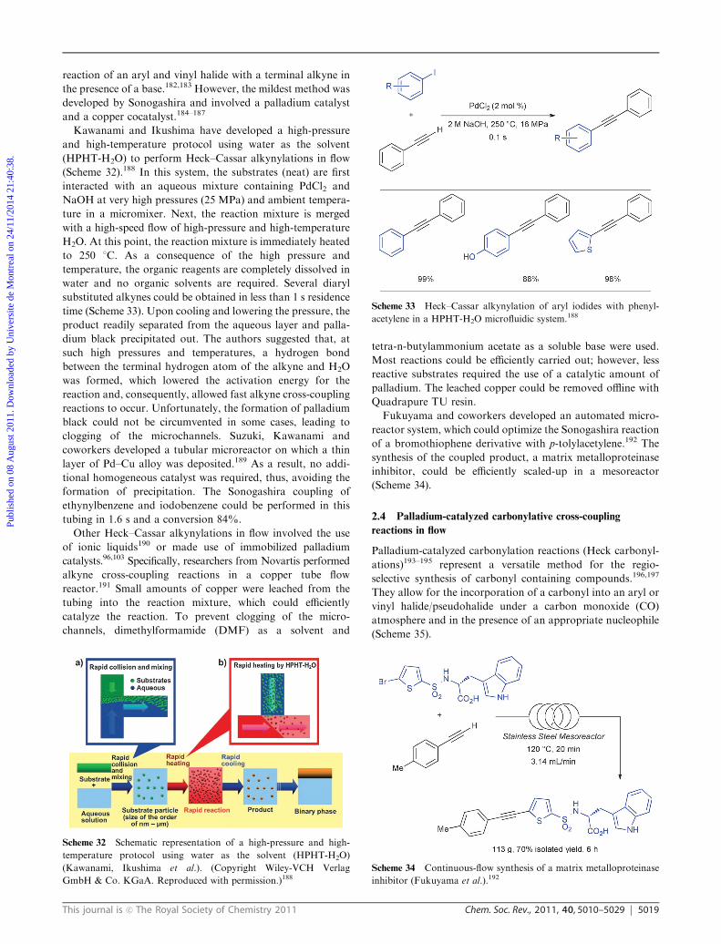
Kawanami and Ikushima have developed a high-pressure
and high-temperature protocol using water as the solvent
(HPHT-H2O) to perform Heck–Cassar alkynylations in flow
(Scheme 32).188 In this system, the substrates (neat) are first
interacted with an aqueous mixture containing PdCl2 and
NaOH at very high pressures (25 MPa) and ambient tempera-
ture in a micromixer. Next, the reaction mixture is merged
with a high-speed flow of high-pressure and high-temperature
H2O. At this point, the reaction mixture is immediately heated
to 250 1C. As a consequence of the high pressure and
temperature, the organic reagents are completely dissolved in
water and no organic solvents are required. Several diaryl
substituted alkynes could be obtained in less than 1 s residence
time (Scheme 33). Upon cooling and lowering the pressure, the
product readily separated from the aqueous layer and palla-
dium black precipitated out. The authors suggested that, at
such high pressures and temperatures, a hydrogen bond
between the terminal hydrogen atom of the alkyne and H2O
was formed, which lowered the activation energy for the
reaction and, consequently, allowed fast alkyne cross-coupling
reactions to occur. Unfortunately, the formation of palladium
black could not be circumvented in some cases, leading to
clogging of the microchannels. Suzuki, Kawanami and
coworkers developed a tubular microreactor on which a thin
layer of Pd–Cu alloy was deposited.189 As a result, no addi-
tional homogeneous catalyst was required, thus, avoiding the
formation of precipitation. The Sonogashira coupling of
ethynylbenzene and iodobenzene could be performed in this
tubing in 1.6 s and a conversion 84%.
Other Heck–Cassar alkynylations in flow involved the use
of ionic liquids190 or made use of immobilized palladium
catalysts.96,103 Specifically, researchers from Novartis performed
alkyne cross-coupling reactions in a copper tube flow
reactor.191 Small amounts of copper were leached from the
tubing into the reaction mixture, which could efficiently
catalyze the reaction. To prevent clogging of the micro-
channels, dimethylformamide (DMF) as a solvent and
tetra-n-butylammonium acetate as a soluble base were used.
Most reactions could be efficiently carried out; however, less
reactive substrates required the use of a catalytic amount of
palladium. The leached copper could be removed offline with
Quadrapure TU resin.
Fukuyama and coworkers developed an automated micro-
reactor system, which could optimize the Sonogashira reaction
of a bromothiophene derivative with p-tolylacetylene.192 The
synthesis of the coupled product, a matrix metalloproteinase
inhibitor, could be efficiently scaled-up in a mesoreactor
(Scheme 34).
2.4 Palladium-catalyzed carbonylative cross-coupling
reactions in flow
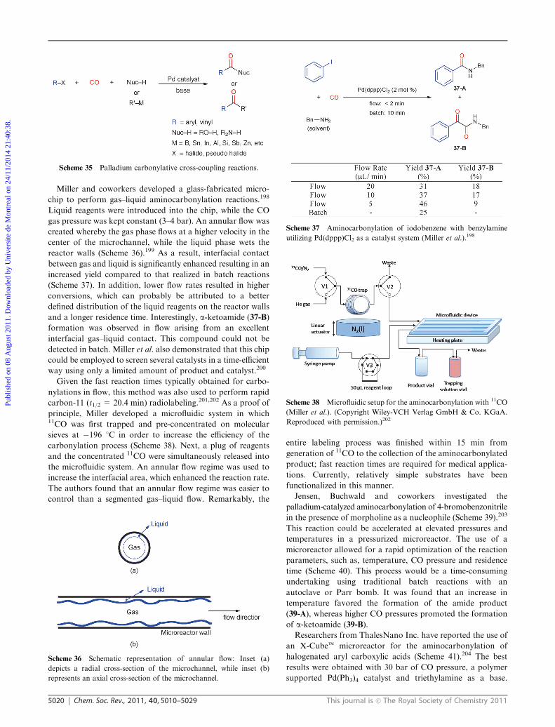
Palladium-catalyzed carbonylation reactions (Heck carbonyl-
ations)193–195 represent a versatile method for the regio-
selective synthesis of carbonyl containing compounds.196,197
They allow for the incorporation of a carbonyl into an aryl or
vinyl halide/pseudohalide under a carbon monoxide (CO)
atmosphere and in the presence of an appropriate nucleophile
(Scheme 35).
Scheme 32 Schematic representation of a high-pressure and high-
temperature protocol using water as the solvent (HPHT-H2O)
(Kawanami, Ikushima et al.). (Copyright Wiley-VCH Verlag
GmbH & Co. KGaA. Reproduced with permission.)188
Scheme 33 Heck–Cassar alkynylation of aryl iodides with phenyl-
acetylene in a HPHT-H2O microfluidic system.188
Scheme 34 Continuous-flow synthesis of a matrix metalloproteinase
inhibitor (Fukuyama et al.).192
Publ
ishe
d on
08
Aug
ust 2
011.
Dow
nloa
ded
by U
nive
rsite
de
Mon
trea
l on
24/1
1/20
14 2
1:40
:38.
View Article Online
5020 Chem. Soc. Rev., 2011, 40, 5010–5029 This journal is c The Royal Society of Chemistry 2011
Miller and coworkers developed a glass-fabricated micro-
chip to perform gas–liquid aminocarbonylation reactions.198
Liquid reagents were introduced into the chip, while the CO
gas pressure was kept constant (3–4 bar). An annular flow was
created whereby the gas phase flows at a higher velocity in the
center of the microchannel, while the liquid phase wets the
reactor walls (Scheme 36).199 As a result, interfacial contact
between gas and liquid is significantly enhanced resulting in an
increased yield compared to that realized in batch reactions
(Scheme 37). In addition, lower flow rates resulted in higher
conversions, which can probably be attributed to a better
defined distribution of the liquid reagents on the reactor walls
and a longer residence time. Interestingly, a-ketoamide (37-B)
formation was observed in flow arising from an excellent
interfacial gas–liquid contact. This compound could not be
detected in batch. Miller et al. also demonstrated that this chip
could be employed to screen several catalysts in a time-efficient
way using only a limited amount of product and catalyst.200
Given the fast reaction times typically obtained for carbo-
nylations in flow, this method was also used to perform rapid
carbon-11 (t1/2 = 20.4 min) radiolabeling.201,202 As a proof of
principle, Miller developed a microfluidic system in which11CO was first trapped and pre-concentrated on molecular
sieves at �196 1C in order to increase the efficiency of the
carbonylation process (Scheme 38). Next, a plug of reagents
and the concentrated 11CO were simultaneously released into
the microfluidic system. An annular flow regime was used to
increase the interfacial area, which enhanced the reaction rate.
The authors found that an annular flow regime was easier to
control than a segmented gas–liquid flow. Remarkably, the
entire labeling process was finished within 15 min from
generation of 11CO to the collection of the aminocarbonylated
product; fast reaction times are required for medical applica-
tions. Currently, relatively simple substrates have been
functionalized in this manner.
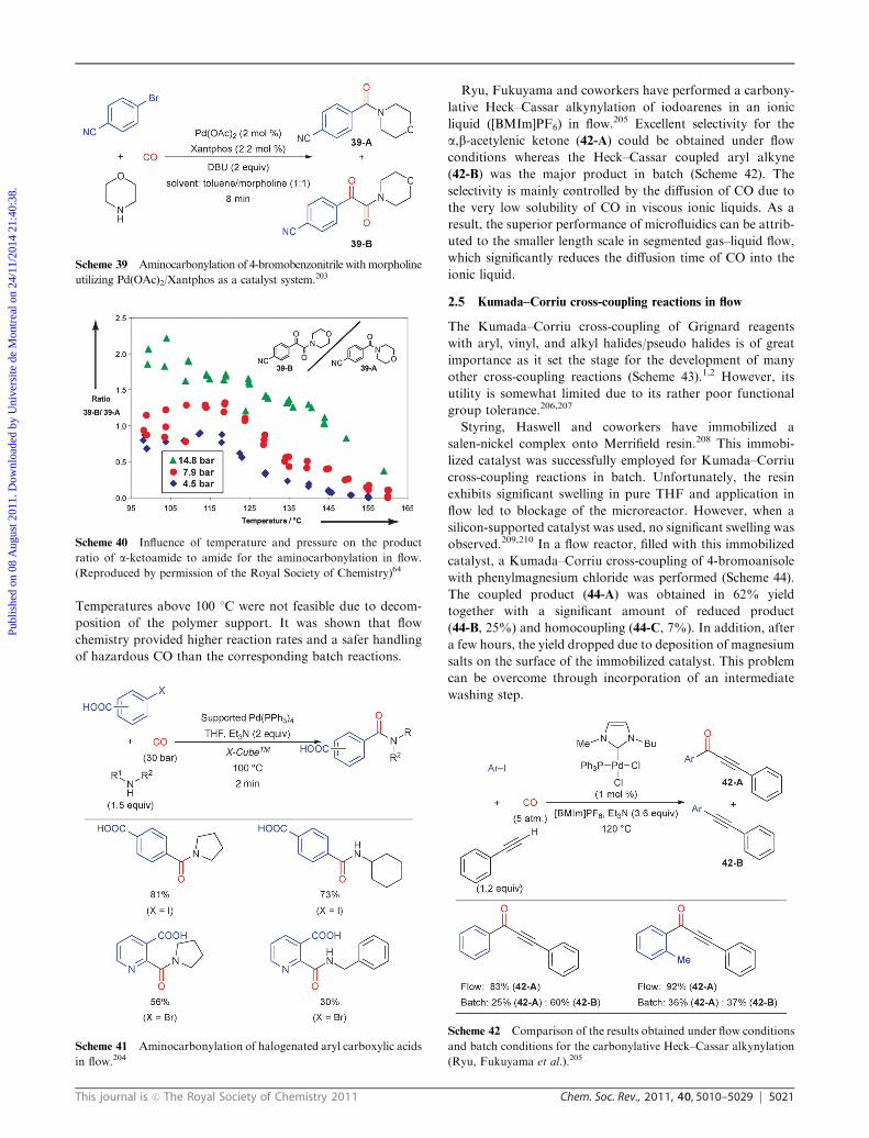
Jensen, Buchwald and coworkers investigated the
palladium-catalyzed aminocarbonylation of 4-bromobenzonitrile
in the presence of morpholine as a nucleophile (Scheme 39).203
This reaction could be accelerated at elevated pressures and
temperatures in a pressurized microreactor. The use of a
microreactor allowed for a rapid optimization of the reaction
parameters, such as, temperature, CO pressure and residence
time (Scheme 40). This process would be a time-consuming
undertaking using traditional batch reactions with an
autoclave or Parr bomb. It was found that an increase in
temperature favored the formation of the amide product
(39-A), whereas higher CO pressures promoted the formation
of a-ketoamide (39-B).
Researchers from ThalesNano Inc. have reported the use of
an X-Cubet microreactor for the aminocarbonylation of
halogenated aryl carboxylic acids (Scheme 41).204 The best
results were obtained with 30 bar of CO pressure, a polymer
supported Pd(Ph3)4 catalyst and triethylamine as a base.
Scheme 35 Palladium carbonylative cross-coupling reactions.
Scheme 36 Schematic representation of annular flow: Inset (a)
depicts a radial cross-section of the microchannel, while inset (b)
represents an axial cross-section of the microchannel.
Scheme 37 Aminocarbonylation of iodobenzene with benzylamine
utilizing Pd(dppp)Cl2 as a catalyst system (Miller et al.).198
Scheme 38 Microfluidic setup for the aminocarbonylation with 11CO
(Miller et al.). (Copyright Wiley-VCH Verlag GmbH & Co. KGaA.
Reproduced with permission.)202
Publ
ishe
d on
08
Aug
ust 2
011.
Dow
nloa
ded
by U
nive
rsite
de
Mon
trea
l on
24/1
1/20
14 2
1:40
:38.
View Article Online
This journal is c The Royal Society of Chemistry 2011 Chem. Soc. Rev., 2011, 40, 5010–5029 5021
Temperatures above 100 1C were not feasible due to decom-
position of the polymer support. It was shown that flow
chemistry provided higher reaction rates and a safer handling
of hazardous CO than the corresponding batch reactions.
Ryu, Fukuyama and coworkers have performed a carbony-
lative Heck–Cassar alkynylation of iodoarenes in an ionic
liquid ([BMIm]PF6) in flow.205 Excellent selectivity for the
a,b-acetylenic ketone (42-A) could be obtained under flow
conditions whereas the Heck–Cassar coupled aryl alkyne
(42-B) was the major product in batch (Scheme 42). The
selectivity is mainly controlled by the diffusion of CO due to
the very low solubility of CO in viscous ionic liquids. As a
result, the superior performance of microfluidics can be attrib-
uted to the smaller length scale in segmented gas–liquid flow,
which significantly reduces the diffusion time of CO into the
ionic liquid.
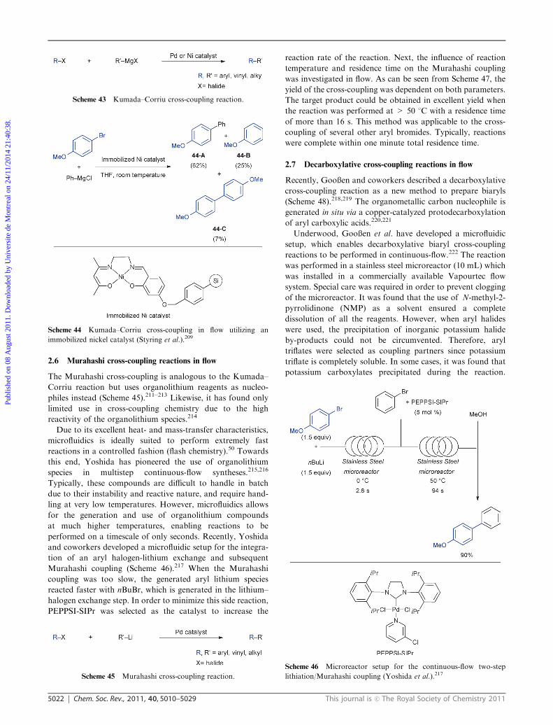
2.5 Kumada–Corriu cross-coupling reactions in flow
The Kumada–Corriu cross-coupling of Grignard reagents
with aryl, vinyl, and alkyl halides/pseudo halides is of great
importance as it set the stage for the development of many
other cross-coupling reactions (Scheme 43).1,2 However, its
utility is somewhat limited due to its rather poor functional
group tolerance.206,207
Styring, Haswell and coworkers have immobilized a
salen-nickel complex onto Merrifield resin.208 This immobi-
lized catalyst was successfully employed for Kumada–Corriu
cross-coupling reactions in batch. Unfortunately, the resin
exhibits significant swelling in pure THF and application in
flow led to blockage of the microreactor. However, when a
silicon-supported catalyst was used, no significant swelling was
observed.209,210 In a flow reactor, filled with this immobilized
catalyst, a Kumada–Corriu cross-coupling of 4-bromoanisole
with phenylmagnesium chloride was performed (Scheme 44).
The coupled product (44-A) was obtained in 62% yield
together with a significant amount of reduced product
(44-B, 25%) and homocoupling (44-C, 7%). In addition, after
a few hours, the yield dropped due to deposition of magnesium
salts on the surface of the immobilized catalyst. This problem
can be overcome through incorporation of an intermediate
washing step.
Scheme 39 Aminocarbonylation of 4-bromobenzonitrile withmorpholine
utilizing Pd(OAc)2/Xantphos as a catalyst system.203
Scheme 40 Influence of temperature and pressure on the product
ratio of a-ketoamide to amide for the aminocarbonylation in flow.
(Reproduced by permission of the Royal Society of Chemistry)64
Scheme 41 Aminocarbonylation of halogenated aryl carboxylic acids
in flow.204
Scheme 42 Comparison of the results obtained under flow conditions
and batch conditions for the carbonylative Heck–Cassar alkynylation
(Ryu, Fukuyama et al.).205
Publ
ishe
d on
08
Aug
ust 2
011.
Dow
nloa
ded
by U
nive
rsite
de
Mon
trea
l on
24/1
1/20
14 2
1:40
:38.
View Article Online
5022 Chem. Soc. Rev., 2011, 40, 5010–5029 This journal is c The Royal Society of Chemistry 2011
2.6 Murahashi cross-coupling reactions in flow
The Murahashi cross-coupling is analogous to the Kumada–
Corriu reaction but uses organolithium reagents as nucleo-
philes instead (Scheme 45).211–213 Likewise, it has found only
limited use in cross-coupling chemistry due to the high
reactivity of the organolithium species.214
Due to its excellent heat- and mass-transfer characteristics,
microfluidics is ideally suited to perform extremely fast
reactions in a controlled fashion (flash chemistry).50 Towards
this end, Yoshida has pioneered the use of organolithium
species in multistep continuous-flow syntheses.215,216
Typically, these compounds are difficult to handle in batch
due to their instability and reactive nature, and require hand-
ling at very low temperatures. However, microfluidics allows
for the generation and use of organolithium compounds
at much higher temperatures, enabling reactions to be
performed on a timescale of only seconds. Recently, Yoshida
and coworkers developed a microfluidic setup for the integra-
tion of an aryl halogen-lithium exchange and subsequent
Murahashi coupling (Scheme 46).217 When the Murahashi
coupling was too slow, the generated aryl lithium species
reacted faster with nBuBr, which is generated in the lithium–
halogen exchange step. In order to minimize this side reaction,
PEPPSI-SIPr was selected as the catalyst to increase the
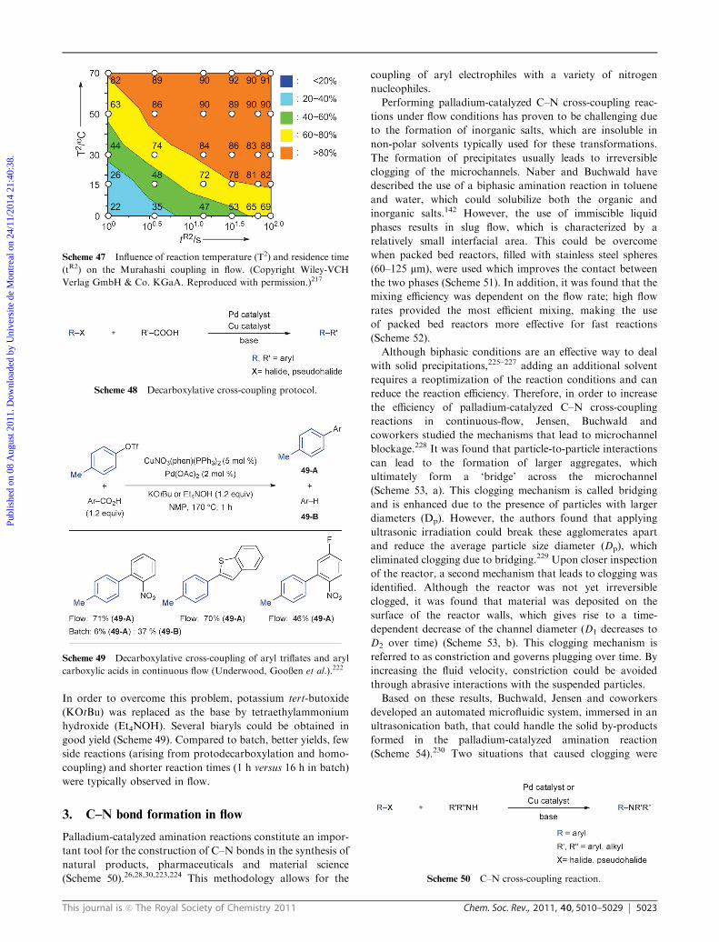
reaction rate of the reaction. Next, the influence of reaction
temperature and residence time on the Murahashi coupling
was investigated in flow. As can be seen from Scheme 47, the
yield of the cross-coupling was dependent on both parameters.
The target product could be obtained in excellent yield when
the reaction was performed at > 50 1C with a residence time
of more than 16 s. This method was applicable to the cross-
coupling of several other aryl bromides. Typically, reactions
were complete within one minute total residence time.
2.7 Decarboxylative cross-coupling reactions in flow
Recently, Gooßen and coworkers described a decarboxylative
cross-coupling reaction as a new method to prepare biaryls
(Scheme 48).218,219 The organometallic carbon nucleophile is
generated in situ via a copper-catalyzed protodecarboxylation
of aryl carboxylic acids.220,221
Underwood, Gooßen et al. have developed a microfluidic
setup, which enables decarboxylative biaryl cross-coupling
reactions to be performed in continuous-flow.222 The reaction
was performed in a stainless steel microreactor (10 mL) which
was installed in a commercially available Vapourtec flow
system. Special care was required in order to prevent clogging
of the microreactor. It was found that the use of N-methyl-2-
pyrrolidinone (NMP) as a solvent ensured a complete
dissolution of all the reagents. However, when aryl halides
were used, the precipitation of inorganic potassium halide
by-products could not be circumvented. Therefore, aryl
triflates were selected as coupling partners since potassium
triflate is completely soluble. In some cases, it was found that
potassium carboxylates precipitated during the reaction.
Scheme 43 Kumada–Corriu cross-coupling reaction.
Scheme 44 Kumada–Corriu cross-coupling in flow utilizing an
immobilized nickel catalyst (Styring et al.).209
Scheme 45 Murahashi cross-coupling reaction.
Scheme 46 Microreactor setup for the continuous-flow two-step
lithiation/Murahashi coupling (Yoshida et al.).217
Publ
ishe
d on
08
Aug
ust 2
011.
Dow
nloa
ded
by U
nive
rsite
de
Mon
trea
l on
24/1
1/20
14 2
1:40
:38.
View Article Online
This journal is c The Royal Society of Chemistry 2011 Chem. Soc. Rev., 2011, 40, 5010–5029 5023
In order to overcome this problem, potassium tert-butoxide
(KOtBu) was replaced as the base by tetraethylammonium
hydroxide (Et4NOH). Several biaryls could be obtained in
good yield (Scheme 49). Compared to batch, better yields, few
side reactions (arising from protodecarboxylation and homo-
coupling) and shorter reaction times (1 h versus 16 h in batch)
were typically observed in flow.
3. C–N bond formation in flow
Palladium-catalyzed amination reactions constitute an impor-
tant tool for the construction of C–N bonds in the synthesis of
natural products, pharmaceuticals and material science
(Scheme 50).26,28,30,223,224 This methodology allows for the
coupling of aryl electrophiles with a variety of nitrogen
nucleophiles.
Performing palladium-catalyzed C–N cross-coupling reac-
tions under flow conditions has proven to be challenging due
to the formation of inorganic salts, which are insoluble in
non-polar solvents typically used for these transformations.
The formation of precipitates usually leads to irreversible
clogging of the microchannels. Naber and Buchwald have
described the use of a biphasic amination reaction in toluene
and water, which could solubilize both the organic and
inorganic salts.142 However, the use of immiscible liquid
phases results in slug flow, which is characterized by a
relatively small interfacial area. This could be overcome
when packed bed reactors, filled with stainless steel spheres
(60–125 mm), were used which improves the contact between
the two phases (Scheme 51). In addition, it was found that the
mixing efficiency was dependent on the flow rate; high flow
rates provided the most efficient mixing, making the use
of packed bed reactors more effective for fast reactions
(Scheme 52).
Although biphasic conditions are an effective way to deal
with solid precipitations,225–227 adding an additional solvent
requires a reoptimization of the reaction conditions and can
reduce the reaction efficiency. Therefore, in order to increase
the efficiency of palladium-catalyzed C–N cross-coupling
reactions in continuous-flow, Jensen, Buchwald and
coworkers studied the mechanisms that lead to microchannel
blockage.228 It was found that particle-to-particle interactions
can lead to the formation of larger aggregates, which
ultimately form a ‘bridge’ across the microchannel
(Scheme 53, a). This clogging mechanism is called bridging
and is enhanced due to the presence of particles with larger
diameters (Dp). However, the authors found that applying
ultrasonic irradiation could break these agglomerates apart
and reduce the average particle size diameter (Dp), which
eliminated clogging due to bridging.229 Upon closer inspection
of the reactor, a second mechanism that leads to clogging was
identified. Although the reactor was not yet irreversible
clogged, it was found that material was deposited on the
surface of the reactor walls, which gives rise to a time-
dependent decrease of the channel diameter (D1 decreases to
D2 over time) (Scheme 53, b). This clogging mechanism is
referred to as constriction and governs plugging over time. By
increasing the fluid velocity, constriction could be avoided
through abrasive interactions with the suspended particles.
Based on these results, Buchwald, Jensen and coworkers
developed an automated microfluidic system, immersed in an
ultrasonication bath, that could handle the solid by-products
formed in the palladium-catalyzed amination reaction
(Scheme 54).230 Two situations that caused clogging were
Scheme 47 Influence of reaction temperature (T2) and residence time
(tR2) on the Murahashi coupling in flow. (Copyright Wiley-VCH
Verlag GmbH & Co. KGaA. Reproduced with permission.)217
Scheme 48 Decarboxylative cross-coupling protocol.
Scheme 49 Decarboxylative cross-coupling of aryl triflates and aryl
carboxylic acids in continuous flow (Underwood, Gooßen et al.).222
Scheme 50 C–N cross-coupling reaction.
Publ
ishe
d on
08
Aug
ust 2
011.
Dow
nloa
ded
by U
nive
rsite
de
Mon
trea
l on
24/1
1/20
14 2
1:40
:38.
View Article Online

5024 Chem. Soc. Rev., 2011, 40, 5010–5029 This journal is c The Royal Society of Chemistry 2011
identified. First, when using precatalysts based on dialkyl
biarylmonophosphines,231–233 reactions were initiated and
finished within seconds. However, these conditions caused
clogging at the tee-mixer due to a fast generation of solids.
Cooling prevented any significant reaction from taking place
in the mixer and, as a result, clogging was prevented. Second,
blockage at the end of the reactor was observed for slower
reactions (reaction time Z 5 min). This could be circumvented
when the reaction was quenched with water and ethyl acetate
in a piece of larger diameter tubing, which provided enough
time for the dissolution of the precipitates. Next, the optimized
system was used in the palladium-catalyzed amination
reaction of aryl chlorides, aryl bromides and aryl triflates
(Scheme 55). It was shown that there was no loss in activity
under continuous-flow conditions. Due to the increased mass-
and heat-transfer in microfluidics, a higher activity was
observed in flow compared to batch at very short residence
times (e.g., 20 s).
In certain cases, the formation of inorganic salts could be
circumvented when soluble organic bases and polar solvents
were employed.121,191 Researchers at Rhodia Recherches
reported that slurrys formed during the amination reaction
could be handled without clogging when high flow rates
(1 mL min�1) and diluted conditions were used.234
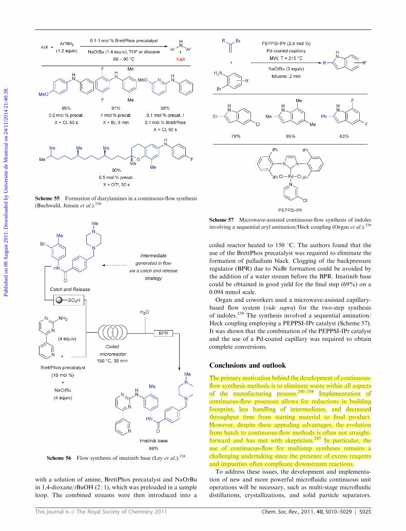
Ley and coworkers have extensively detailed the use of
immobilized reagents, catalysts and scavengers in
flow.70,81,235–237 This strategy allows for the synthesis and
purification of complex molecules without the use of conven-
tional work-up procedures. More recently, Ley reported the
synthesis of imatinib base (Gleevecs) in flow, a protein kinase
inhibitor used in the treatment of chronic myelogenous leukemia
and gastrointestinal stromal tumors (Scheme 56).238 The final
step involved a palladium-catalyzed C–N cross-coupling
reaction. The intermediate for the C–N coupling was synthe-
sized in flow using a ‘catch and release’ strategy, which allowed
for purifications and solvent switches in an automated fashion.
Next, this intermediate was loaded on a silica-supported
sulfonic acid column and was, subsequently, released with
DBU and 1,4-dioxane/tBuOH (2 : 1). This stream was merged
Scheme 51 Mixing of fluid elements in a packed bed reactor.
Scheme 52 Comparison of the yield obtained in a packed bed reactor
and an open tube reactor for the coupling of o-chloroanisole and ethyl
2-aminobenzoate under biphasic conditions (Naber and Buchwald).142
Scheme 53 Schematic representation of the clogging mechanisms
observed in continuous-flow palladium-catalyzed aminations: Inset
(a) shows bridging, while inset (b) depicts constriction.
Scheme 54 Microreactor setup that can handle solids formed during
the palladium-catalyzed C–N cross-coupling reactions (Buchwald,
Jensen et al.).230
Publ
ishe
d on
08
Aug
ust 2
011.
Dow
nloa
ded
by U
nive
rsite
de
Mon
trea
l on
24/1
1/20
14 2
1:40
:38.
View Article Online
This journal is c The Royal Society of Chemistry 2011 Chem. Soc. Rev., 2011, 40, 5010–5029 5025
with a solution of amine, BrettPhos precatalyst and NaOtBu
in 1,4-dioxane/tBuOH (2 : 1), which was preloaded in a sample
loop. The combined streams were then introduced into a
coiled reactor heated to 150 1C. The authors found that the
use of the BrettPhos precatalyst was required to eliminate the
formation of palladium black. Clogging of the backpressure
regulator (BPR) due to NaBr formation could be avoided by
the addition of a water stream before the BPR. Imatinib base
could be obtained in good yield for the final step (69%) on a
0.094 mmol scale.
Organ and coworkers used a microwave-assisted capillary-
based flow system (vide supra) for the two-step synthesis
of indoles.239 The synthesis involved a sequential amination/
Heck coupling employing a PEPPSI-IPr catalyst (Scheme 57).
It was shown that the combination of the PEPPSI-IPr catalyst
and the use of a Pd-coated capillary was required to obtain
complete conversions.
Conclusions and outlook
The primary motivation behind the development of continuous-
flow synthesis methods is to eliminate waste within all aspects
of the manufacturing process.240–244 Implementation of
continuous-flow processes allows for reductions in building
footprint, less handling of intermediates, and decreased
throughput time from starting material to final product.
However, despite these appealing advantages, the evolution
from batch to continuous-flow methods is often not straight-
forward and has met with skepticism.245 In particular, the
use of continuous-flow for multistep syntheses remains a
challenging undertaking since the presence of excess reagents
and impurities often complicate downstream reactions.
To address these issues, the development and implementa-
tion of new and more powerful microfluidic continuous unit
operations will be necessary, such as multi-stage microfluidic
distillations, crystallizations, and solid particle separators.
Scheme 55 Formation of diarylamines in a continuous-flow synthesis
(Buchwald, Jensen et al.).230
Scheme 56 Flow synthesis of imatinib base (Ley et al.).238
Scheme 57 Microwave-assisted continuous-flow synthesis of indoles
involving a sequential aryl amination/Heck coupling (Organ et al.).239
Publ
ishe
d on
08
Aug
ust 2
011.
Dow
nloa
ded
by U
nive
rsite
de
Mon
trea
l on
24/1
1/20
14 2
1:40
:38.
View Article Online
5026 Chem. Soc. Rev., 2011, 40, 5010–5029 This journal is c The Royal Society of Chemistry 2011
Moreover, in order to run the continuous manufacturing
process at a steady state without any intermediate handling,
advances in the development of robust process control systems
are expected. Realization of these goals will require a multi-
disciplinary approach in which chemists, engineers, software
developers are involved.
A remarkable amount of progress has been reported during
the last few years for the application of cross-coupling
reactions in continuous-flow. Enhanced reactivities and
selectivities compared to batch are typically observed. In
continuous-flow, cross-coupling reactions can be performed
under conditions that cannot be easily realized in traditional
reaction flasks due to safety reasons (e.g., use of solvents at
elevated temperatures and pressures). However, many
opportunities still remain for improvement in these systems.
Notably, the development of more efficient catalyst recycling
systems would be interesting from an economical and
ecological standpoint and would require the development of
highly stable catalyst systems and innovative catalyst recycling
units. Additionally, active pharmaceutical ingredients (API)
are typically highly polar and insoluble in many solvents,
rendering them difficult to handle in microfluidic systems.246
Thus, the development of devices that can introduce and
handle slurries is of utmost importance.
Acknowledgements
T.N. and S.L.B. acknowledge the Novartis International AG
for funding. The authors would like to thank the members of
the Novartis-MIT Center for Continuous Manufacturing
(CCM) for the helpful and stimulating discussions. T.N. is
currently a Fulbright Postdoctoral Fellow.
Notes and references
1 K. Tamao, K. Sumitani and M. Kumada, J. Am. Chem. Soc.,1972, 94, 4374–4376.
2 R. J. P. Corriu and J. P. Masse, J. Chem. Soc., Chem. Commun.,1972, 144a.
3 E.-i. Negishi, J. Organomet. Chem., 2002, 653, 34–40.4 F. Diederich and A. de Meijere, Metal-Catalyzed Cross-CouplingReactions, Wiley-VCH, New York, 2004.
5 N. Miyaura, Cross-Coupling Reactions, A Practical Guide, Top.Curr. Chem., 2002, 219, 1–241.
6 N. Miyaura and A. Suzuki, J. Chem. Soc., Chem. Commun., 1979,866–867.
7 N. Miyaura, K. Yamada and A. Suzuki, Tetrahedron Lett., 1979,20, 3437–3440.
8 E. Negishi and S. Baba, J. Chem. Soc., Chem. Commun., 1976,596b–597.
9 S. Baba and E. Negishi, J. Am. Chem. Soc., 1976, 98, 6729–6731.10 Y. Hatanaka and T. Hiyama, J. Org. Chem., 1988, 53, 918–920.11 M. Kosugi, K. Sasazawa, Y. Shimizu and T. Migita, Chem. Lett.,
1977, 301–302.12 M. Kosugi, Y. Shimizu and T. Migita, Chem. Lett., 1977,
1423–1424.13 M. Kosugi, Y. Shimizu and T. Migita, J. Organomet. Chem.,
1977, 129, C36–C38.14 D. Milstein and J. K. Stille, J. Am. Chem. Soc., 1978, 100,
3636–3638.15 A. S. Guram and S. L. Buchwald, J. Am. Chem. Soc., 1994, 116,
7901–7902.16 A. S. Guram, R. A. Rennels and S. L. Buchwald, Angew. Chem.,
Int. Ed. Engl., 1995, 34, 1348–1350.17 J. Louie and J. F. Hartwig, Tetrahedron Lett., 1995, 36,
3609–3612.
18 M. Palucki, J. P. Wolfe and S. L. Buchwald, J. Am. Chem. Soc.,1996, 118, 10333–10334.
19 M. Palucki, J. P. Wolfe and S. L. Buchwald, J. Am. Chem. Soc.,1997, 119, 3395–3396.
20 M. Murata and S. L. Buchwald, Tetrahedron, 2004, 60,7397–7403.
21 M. A. Fernandez-Rodriguez, Q. L. Shen and J. F. Hartwig,J. Am. Chem. Soc., 2006, 128, 2180–2181.
22 K. C. Nicolaou, P. G. Bulger and D. Sarlah, Angew. Chem., Int.Ed., 2005, 44, 4442–4489.
23 B. Rieger, L. S. Baugh, S. Kacker and S. Striegler, Late TransitionMetal Polymerization Catalysis, Wiley-VCH, Weinheim, 2006.
24 T. A. Skotheim and J. R. Reynolds, Conjugated Polymers:Theory, Synthesis, Properties, and Characterization, CRC Press,John Reynolds, 2006.
25 J. Sakamoto, M. Rehahn, G. Wegner and A. D. Schluter, Macro-mol. Rapid Commun., 2009, 30, 653–687.
26 D. S. Surry and S. L. Buchwald, Chem. Sci., 2011, 2, 27–50.27 D. S. Surry and S. L. Buchwald, Chem. Sci., 2010, 1, 13–31.28 D. S. Surry and S. L. Buchwald, Angew. Chem., Int. Ed., 2008, 47,
6338–6361.29 R. Martin and S. L. Buchwald, Acc. Chem. Res., 2008, 41,
1461–1473.30 J. F. Hartwig, Acc. Chem. Res., 2008, 41, 1534–1544.31 N. Marion and S. P. Nolan, Acc. Chem. Res., 2008, 41,
1440–1449.32 S. Wurtz and F. Glorius, Acc. Chem. Res., 2008, 41, 1523–1533.33 A. F. Littke and G. C. Fu, Angew. Chem., Int. Ed., 2002, 41,
4176–4211.34 A. Furstner, A. Leitner, M. Mendez and H. Krause, J. Am. Chem.
Soc., 2002, 124, 13856–13863.35 B. D. Sherry and A. Furstner, Acc. Chem. Res., 2008, 41,
1500–1511.36 J. Terao and N. Kambe, Acc. Chem. Res., 2008, 41, 1545–1554.37 D. Ma and Q. Cai, Acc. Chem. Res., 2008, 41, 1450–1460.38 B. H. Lipshutz, A. R. Abela, Z. V. Boskovic, T. Nishikata,
C. Duplais and A. Krasovskiy, Top. Catal., 2010, 53, 985–990.39 B. H. Lipshutz and S. Ghorai, Aldrichim. Acta, 2008, 41, 59–72.40 R. Franzen and Y. Xu, Can. J. Chem., 2005, 83, 266–272.41 V. Polshettiwar, A.Decottignies, C. Len andA. Fihri,ChemSusChem,
2010, 3, 502–522.42 M. Lamblin, L. Nassar-Hardy, J.-C. Hierso, E. Fouquet and
F.-X. Felpin, Adv. Synth. Catal., 2010, 352, 33–79.43 P. J. Dyson and T. J. Geldbach, Metal Catalysed Reactions in
Ionic Liquids, Springer, Dordrecht, 2005.44 P. Wasserscheid and T. Welton, Ionic Liquids in Synthesis,
Wiley-VCH, Weinheim, 2008.45 R. E. Tundel, K. W. Anderson and S. L. Buchwald, J. Org.
Chem., 2006, 71, 430–433.46 P. Appukkuttan and E. Van der Eycken, Eur. J. Org. Chem.,
2008, 1133–1155.47 P. Nilsson, K. Olofsson and M. Larhed, Top. Curr. Chem., 2006,
266, 103–144.48 B. A. Roberts and C. R. Strauss, Acc. Chem. Res., 2005, 38, 653–661.49 T. Wirth, Microreactors in Organic Synthesis and Catalysis,
Wiley-VCH, Weinheim, 2008.50 J.-i. Yoshida, Flash Chemistry: fast organic synthesis in Micro-
systems, Wiley-Blackwell, Hoboken, 2008.51 P. H. Seeberger and T. Blume, New Avenues to Efficient Chemical
Synthesis-Emerging Technologies, Springer-Verlag, Berlin, 2007.52 W. Ehrfeld, V. Hessel and H. Lowe,Microreactors: New Technology
for Modern Chemistry, Wiley-VCH, Weinheim, 2000.53 J. Wegner, S. Ceylan and A. Kirschning, Chem. Commun., 2011,
47, 4583–4592.54 U. Hintermair, G. Francio and W. Leitner, Chem. Commun.,
2011, 47, 3691–3701.55 J.-i. Yoshida, H. Kim and A. Nagaki, ChemSusChem, 2011, 4,
331–340.56 D. Webb and T. F. Jamison, Chem. Sci., 2010, 1, 675–680.57 S. Marre and K. F. Jensen, Chem. Soc. Rev., 2010, 39, 1183–1202.58 A. Cukalovic, J.-C. M. R. Monbaliu and C. V. Stevens, Top.
Heterocycl. Chem., 2010, 23, 161–198.59 C. G. Frost and L. Mutton, Green Chem., 2010, 12, 1687–1703.60 T. N. Glasnov and C. O. Kappe, J. Heterocycl. Chem., 2011, 48,
11–30.
Publ
ishe
d on
08
Aug
ust 2
011.
Dow
nloa
ded
by U
nive
rsite
de
Mon
trea
l on
24/1
1/20
14 2
1:40
:38.
View Article Online
This journal is c The Royal Society of Chemistry 2011 Chem. Soc. Rev., 2011, 40, 5010–5029 5027
61 D. Mark, S. Haeberle, G. Roth, F. von Stetten and R. Zengerle,Chem. Soc. Rev., 2010, 39, 1153–1182.
62 X. Y. Mak, P. Laurino and P. H. Seeberger, Beilstein J. Org.Chem., 2009, 5, DOI: 10.3762/bjoc.5.19.
63 P. H. Seeberger, Nat. Chem., 2009, 1, 258–260.64 R. L. Hartman and K. F. Jensen, Lab Chip, 2009, 9, 2495–2507.65 W.-Y. Lin, Y. Wang, S. Wang and H.-R. Tseng, Nano Today,
2009, 4, 470–481.66 K. Geyer, T. Gustafsson and P. H. Seeberger, Synlett, 2009,
2382–2391.67 B. K. Singh, N. Kaval, S. Tomar, E. Van der Eycken and
V. S. Parmar, Org. Process Res. Dev., 2008, 12, 468–474.68 T. Fukuyama, M. T. Rahman, M. Sato and I. Ryu, Synlett, 2008,
2, 151–163.69 J.-i. Yoshida, A. Nagaki and T. Yamada, Chem.–Eur. J., 2008,
14, 7450–7459.70 S. V. Ley and I. R. Baxendale, Chimia, 2008, 62, 162–168.71 C. Wiles and P. Watts, Eur. J. Org. Chem., 2008, 1655–1671.72 B. P. Mason, K. E. Price, J. L. Steinbacher, A. R. Bogdan and
D. T. McQuade, Chem. Rev., 2007, 107, 2300–2318.73 G. M. Whitesides, Nature, 2006, 442, 368–373.74 K. Geyer, J. D. C. Codee and P. H. Seeberger, Chem.–Eur. J.,
2006, 12, 8434–8442.75 A. Kirschning, W. Solodenko and K. Mennecke, Chem.–Eur. J.,
2006, 12, 5972–5990.76 K. Jahnisch, V. Hessel, H. Lowe and M. Baerns, Angew. Chem.,
Int. Ed., 2004, 43, 406–446.77 H. Pennemann, V. Hessel and H. Lowe, Chem. Eng. Sci., 2004,
59, 4789–4794.78 G. Jas and A. Kirschning, Chem.–Eur. J., 2003, 9, 5708–5723.79 S. J. Haswell and P. Watts, Green Chem., 2003, 5, 240–249.80 P. I. Fletcher, S. J. Haswell, E. Pombo-Villar, B. H. Warrington,
P. Watts, S. Y. F. Wong and X. Zhang, Tetrahedron, 2002, 58,4735–4757.
81 S. V. Ley and I. R. Baxendale, Nat. Rev. Drug Discovery, 2002, 1,573–586.
82 K. F. Jensen, Chem. Eng. Sci., 2001, 56, 293–303.83 S. J. Haswell, R. J. Middleton, B. O’Sullivan, V. Skelton, P. Watts
and P. Styring, Chem. Commun., 2001, 391–398.84 C. Jimenez-Gonzalez, P. Poechlauer, Q. B. Broxterman,
B.-S. Yang, D. am Ende, J. Baird, C. Bertsch, R. E. Hannah,P. Dell’Orco, H. Noorman, S. Yee, R. Reintjens, A. Wells,V. Massonneau and J. Manley, Org. Process Res. Dev., 2011,DOI: 10.1021/op100327d.
85 D. Lombardi and P. S. Dittrich, Expert Opin. Drug Discovery,2010, 5, 1081–1094.
86 N. Miyaura, in Metal-Catalyzed Cross-Coupling Reactions, ed.F. Diederich and A. de Meijere, Wiley-VCH, New York, 2004,pp. 41–123.
87 F. Bellina, A. Carpita and R. Rossi, Synthesis, 2004, 115,2419–2440.
88 N. Miyaura and A. Suzuki, Chem. Rev., 1995, 95, 2457–2483.89 D. G. Hall, Boronic Acids—Preparation and Applications in
Organic Synthesis and Medicine, Wiley-VCH, Weinheim, 2005.90 Z. Wang, G. Chen and K. Ding, Chem. Rev., 2009, 109, 322–359.91 J. Lu and P. H. Troy, Chem. Rev., 2009, 109, 815–838.92 M. Benaglia, Recoverable and Recyclable Catalysts, Wiley-VCH,
Weinheim, 2009.93 A. Kirschning and G. Jas, Top. Curr. Chem., 2004, 242, 209–239.94 G. M. Greenway, S. J. Haswell, D. O. Morgan, V. Skelton and
P. Styring, Sens. Actuators, B, 2000, 63, 153–158.95 K. Mennecke and A. Kirschning, Beilstein J. Org. Chem., 2009, 5,
DOI: 10.3762/bjoc.5.21.96 A. Gomann, J. A. Deverell, K. F. Munting, R. C. Jones,
T. Rodemann, A. J. Canty, J. A. Smith and R. M. Guijt, Tetra-hedron, 2009, 65, 1450–1454.
97 R. C. Jones, A. J. Canty, J. A. Deverell, M. G. Gardiner,R. M. Guijt, T. Rodemann, J. A. Smith and V.-A. Tolhurst,Tetrahedron, 2009, 65, 7474–7481.
98 K. Mennecke and A. Kirschning, Synthesis, 2008, 3267–3272.99 K. Mennecke, W. Sodolenko and A. Kirschning, Synthesis, 2008,
1589–1599.100 K. F. Bolton, A. J. Canty, J. A. Deverell, R. M. Guijt,
E. F. Hilder, T. Rodemann and J. A. Smith, Tetrahedron Lett.,2006, 47, 9321–9324.
101 W. Sodolenko, K. Mennecke, C. Vogt, S. Gruhl andA. Kirschning, Synthesis, 2006, 1873–1881.
102 U. Kunz, H. Schonfeld, W. Sodolenko, G. Jas and A. Kirschning,Ind. Eng. Chem. Res., 2005, 44, 8458–8467.
103 W. Sodolenko, H. Wen, S. Leue, F. Stuhlmann, G. Sourkouni-Argirusi, G. Jas, H. Schonfeld, U. Kunz and A. Kirschning,Eur. J. Org. Chem., 2004, 3601–3610.
104 U. Kunz, H. Schonfeld, A. Kirschning and W. Sodolenko,J. Chromatogr., A, 2003, 1006, 241–249.
105 N. T. S. Phan, J. Khan and P. Styring, Tetrahedron, 2005, 61,12065–12073.
106 C. K. Y. Lee, A. B. Holmes, S. V. Ley, I. F. McConvey,B. Al-Duri, G. A. Leeke, R. C. D. Santos and J. P K. Seville,Chem. Commun., 2005, 2175–2177.
107 G. A. Leeke, R. C. D. Santos, B. Al-Duri, J. P K. Seville,C. J. Smith, C. K. Y. Lee, A. B. Holmes and I. F. McConvey,Org. Process Res. Dev., 2007, 11, 144–148.
108 I. W. Davies, L. Matty, D. L. Hughes and P. J. Reider, J. Am.Chem. Soc., 2001, 123, 10139–10140.
109 D. E. Bergbreiter, P. L. Osburn and J. D. Frels, Adv. Synth.Catal., 2005, 347, 172–184.
110 K. Yu, W. Sommer, J. M. Richardson, M.Weck and C. W. Jones,Adv. Synth. Catal., 2005, 347, 161–171.
111 C. M. Hagen, J. A. Widegren, P. M. Maitlis and R. G. Finke,J. Am. Chem. Soc., 2005, 127, 4423–4432.
112 S. J. Broadwater and D. T. McQuade, J. Org. Chem., 2006, 71,2131–2134.
113 J. M. Richardson and C. W. Jones, J. Catal., 2007, 251, 80–93.114 M. Weck and C. W. Jones, Inorg. Chem., 2007, 46, 1865–1875.115 S. Reimann, J. Stotzel, R. Frahm, W. Kleist, J.-D. Grunwaldt and
A. Baiker, J. Am. Chem. Soc., 2011, 133, 3921–3930.116 Y. Uozumi, Y. M. A. Yamada, T. Beppu, N. Fukuyama,
M. Ueno and T. Kitamori, J. Am. Chem. Soc., 2006, 128,15994–15995.
117 Y. M. A. Yamada, T. Watanabe, K. Torii and Y. Uozumi, Chem.Commun., 2009, 5594–5596.
118 Y. M. A. Yamada, T. Watanabe, T. Beppu, N. Fukuyama,K. Torii and Y. Uozumi, Chem.–Eur. J., 2010, 16, 11311–11319.
119 A. B. Theberge, G. Whyte, M. Frenzel, L. M. Fidalgo,R. C. R. Wootton and W. T. S. Huck, Chem. Commun., 2009,6225–6227.
120 T. Razzaq and C. O. Kappe, Chem.–Asian J., 2010, 5, 1274–1289.121 S. Ceylan, C. Friese, C. Lammel, K. Mazac and A. Kirschning,
Angew. Chem., Int. Ed., 2008, 47, 8950–8953.122 S. Ceylan, L. Coutable, J. Wegner and A. Kirschning,
Chem.–Eur. J., 2011, 17, 1884–1893.123 A. Schatz, O. Reiser and W. J. Stark, Chem.–Eur. J., 2010, 16,
8950–8967.124 T. N. Glasnov and C. O. Kappe, Macromol. Rapid Commun.,
2007, 28, 395–410.125 I. R. Baxendale, J. J. Hayward and S. V. Ley, Comb. Chem. High
Throughput Screening, 2007, 10, 802–836.126 P. He, S. J. Haswell and P. D. I. Fletcher, Lab Chip, 2004, 4, 38–41.127 P. He, S. J. Haswell and P. D. I. Fletcher, Appl. Catal., A, 2004,
274, 111–114.128 E. Comer and M. G. Organ, J. Am. Chem. Soc., 2005, 127,
8160–8167.129 G. Shore, S. Morin and M. G. Organ, Angew. Chem., Int. Ed.,
2006, 45, 2761–2766.130 G. Shore, W.-J. Yoo, C.-J. Li and M. G. Organ, Chem.–Eur. J.,
2010, 16, 126–133.131 E. Comer and M. G. Organ, Chem.–Eur.J., 2005, 11, 7223–7227.132 C. Ramarao, S. V. Ley, S. C. Smith, I. M. Shirley and
N. DeAlmeida, Chem. Commun., 2002, 1132–1133.133 I. R. Baxendale, C. M. Griffiths-Jones, S. V. Ley and
G. K. Tranmer, Chem.–Eur. J., 2006, 12, 4407–4416.134 H. Lehmann, in New Avenues to Efficient Chemical Synthesis-
Emerging Technologies, ed. P. H. Seeberger and T. Blume,Springer-Verlag, Berlin, 2007, pp. 133–149.
135 N. S. Wilson, C. R. Sarko and G. P. Roth,Org. Process Res. Dev.,2004, 8, 535–538.
136 O. Benali, M. Deal, E. Farrant, D. Tapolczay and R. Wheeler,Org. Process Res. Dev., 2008, 12, 1007–1011.
137 T. Noel, S. Kuhn, A. J. Musacchio, K. F. Jensen andS. L. Buchwald, Angew. Chem., Int. Ed., 2011, 50, 5943–5946.
Publ
ishe
d on
08
Aug
ust 2
011.
Dow
nloa
ded
by U
nive
rsite
de
Mon
trea
l on
24/1
1/20
14 2
1:40
:38.
View Article Online
5028 Chem. Soc. Rev., 2011, 40, 5010–5029 This journal is c The Royal Society of Chemistry 2011
138 J. G. Kralj, H. R. Sahoo and K. F. Jensen, Lab Chip, 2007, 7,256–263.
139 H. R. Sahoo, J. G. Kralj and K. F. Jensen, Angew. Chem., Int.Ed., 2007, 46, 5704–5708.
140 T. Kinzel, Y. Zhang and S. L. Buchwald, J. Am. Chem. Soc.,2010, 132, 14073–14075.
141 X. Huang, K. W. Anderson, D. Zim, L. Jiang, A. Klapars andS. L. Buchwald, J. Am. Chem. Soc., 2003, 125, 6653–6655.
142 J. R. Naber and S. L. Buchwald, Angew. Chem., Int. Ed., 2010, 49,9469–9474.
143 T. N. Glasnov and C. O. Kappe, Adv. Synth. Catal., 2010, 352,3089–3097.
144 R. F. Heck, J. Am. Chem. Soc., 1968, 90, 5518–5526.145 T. Mizoroki, K. Mori and A. Ozaki, Bull. Chem. Soc. Jpn., 1971,
44, 581.146 R. F. Heck and J. P. Nolley Jr., J. Org. Chem., 1972, 37,
2320–2322.147 H. A. Dieck and R. F. Heck, J. Am. Chem. Soc., 1974, 96,
1133–1136.148 M. Oestreich, The Mizoroki–Heck Reaction, Wiley-VCH,
Weinheim, 2009.149 I. P. Beletskaya and A. V. Cheprakov, Chem. Rev., 2000, 100,
3009–3066.150 S. Brase and A. de Meijere, in Metal-Catalyzed Cross-Coupling
Reactions, ed. F. Diederich and A. de Meijere, Wiley-VCH,New York, 2004, pp. 217–315.
151 M. Prashad, Top. Organomet. Chem., 2004, 6, 181–203.152 M. S. Stephan and J. G. De Vries, Chem. Ind., 2001, 82, 379–390.153 J. T. Link and L. E. Overman, inMetal-Catalyzed Cross-Coupling
Reactions, ed. F. Diederich and P. J. Stang, Wiley-VCH,New York, 1998, pp. 231–266.
154 A. B. Dounay and L. E. Overman, Chem. Rev., 2003, 103,2945–2963.
155 N. Nikbin, M. Ladlow and S. V. Ley, Org. Process Res. Dev.,2007, 11, 458–462.
156 N. Karbass, V. Sans, E. Garcia-Verdugo, M. I. Burguete andS. V. Luis, Chem. Commun., 2006, 3095–3097.
157 U. Kunz, A. Kirschning, H.-L. Wen, W. Sodolenko, R. Cecilia,C. O. Kappe and T. Turek, Catal.Today, 2005, 105, 318–324.
158 D. A. Snyder, C. Noti, P. H. Seeberger, F. Schael, T. Bieber,G. Rimmel and W. Ehrfeld, Helv. Chim. Acta, 2005, 88, 1–9.
159 X. Fan, M. G. Manchon, K. Wilson, S. Tennison,A. Kozynchenko, A. A. Lapkin and P. K. Plucinski, J. Catal.,2009, 267, 114–120.
160 T. N. Glasnov, S. Findenig and C. O. Kappe, Chem.–Eur. J.,2009, 15, 1001–1010.
161 K. W. Moore, A. Pechen, X.-J. Feng, J. Dominy, V. Beltrani andH. Rabitz, Chem. Sci., 2011, 2, 417–424.
162 J. P. McMullen, M. T. Stone, S. L. Buchwald and K. F. Jensen,Angew. Chem., Int. Ed., 2010, 49, 7076–7080.
163 J. P. McMullen and K. F. Jensen, Annu. Rev. Anal. Chem., 2010,3, 19–42.
164 M. Rasheed and T. Wirth, Angew. Chem., Int. Ed., 2011, 50,357–358.
165 S. Liu, T. Fukuyama, M. Sato and I. Ryu, Synlett, 2004, 1814–1816.166 S. Liu, T. Fukuyama, M. Sato and I. Ryu,Org. Process Res. Dev.,
2004, 8, 477–481.167 H. A. Dieck and R. F. Heck, J. Org. Chem., 1975, 40, 1083–1090.168 K. M. Gligorich and M. S. Sigman, Chem. Commun., 2009,
3854–3867.169 S. S. Stahl, Angew. Chem., Int. Ed., 2004, 43, 3400–3420.170 C. P. Park and D.-P. Kim, J. Am. Chem. Soc., 2010, 132,
10102–10106.171 L. R. Odell, J. Lindh, T. Gustafsson and M. Lahred, Eur. J. Org.
Chem., 2010, 2270–2274.172 S. Achanta, V. Liautard, R. Paugh and M. G. Organ, Chem.–Eur. J.,
2010, 16, 12797–12800.173 R. L. Hartman, H. R. Sahoo, B. C. Yen and K. F. Jensen, Lab
Chip, 2009, 9, 1843–1849.174 R. L. Hartman, J. R. Naber, S. L. Buchwald and K. F. Jensen,
Angew. Chem., Int. Ed., 2010, 49, 899–903.175 B. Ahmed, D. Barrow and T. Wirth, Adv. Synth. Catal., 2006,
348, 1043–1048.176 B. Ahmed-Omer, D. A. Barrow and T. Wirth, Tetrahedron Lett.,
2009, 50, 3352–3355.
177 B. Ahmed-Omer, D. A. Barrow and T. Wirth, Arkivoc, 2011,26–36.
178 K. Kikukawa, K. Maemura, Y. Kiseki, F. Wada and T. Matsuda,J. Org. Chem., 1981, 46, 4885–4888.
179 A. Roglans, A. Pla-Quitana and M. Moreno-Manas, Chem. Rev.,2006, 106, 4622–4643.
180 C. E. Castro and R. D. Stephens, J. Org. Chem., 1963, 28, 2163.181 R. D. Stephens and C. E. Castro, J. Org. Chem., 1963, 28,
3313–3315.182 H. A. Dieck andR. F. Heck, J. Organomet. Chem., 1975, 93, 259–263.183 L. Cassar, J. Organomet. Chem., 1975, 93, 253–257.184 K. Sonogashira, Y. Tohda and N. Hagihara, Tetrahedron Lett.,
1975, 16, 4467–4470.185 R. Chinchilla and C. Najera, Chem. Rev., 2007, 107, 874–922.186 J. A. Marsden and M. M. Haley, in Metal-Catalyzed Cross-
Coupling Reactions, ed. F. Diederich and A. de Meijere,Wiley-VCH, New York, 2004, pp. 317–394.
187 E.-i. Negishi and L. Anastasia, Chem. Rev., 2003, 103, 1979–2017.188 H. Kawanami, K. Matsushima, M. Sato and Y. Ikushima,
Angew. Chem., Int. Ed., 2007, 46, 5129–5132.189 R. Javaid, H. Kawanami, M. Chatterjee, T. Ishizaka, A. Suzuki
and T. M. Suzuki, Chem. Eng. J., 2011, 167, 431–435.190 T. Fukuyama, M. Shinmen, S. Nishitani, M. Sato and I. Ryu,
Org. Lett., 2002, 4, 1691–1694.191 Y. Zhang, T. F. Jamison, S. Patel and N. Mainolfi, Org. Lett.,
2011, 13, 280–283.192 A. Sugimoto, T. Fukuyama, M. T. Rahman and I. Ryu,
Tetrahedron Lett., 2009, 50, 6364–6367.193 A. Schoenberg, I. Bartoletti and R. F. Heck, J. Org. Chem., 1974,
39, 3318–3326.194 A. Schoenberg and R. F. Heck, J. Org. Chem., 1974, 39,
3327–3331.195 A. Schoenberg and R. F. Heck, J. Am. Chem. Soc., 1974, 96,
7761–7764.196 A. Brennfuhrer, H. Neumann and M. Beller, Angew. Chem., Int.
Ed., 2009, 48, 4114–4133.197 C. F. J. Barnard, Organometallics, 2008, 27, 5402–5422.198 P. W. Miller, N. J. Long, A. J. de Mello, R. Vilar, J. Passchier and
A. Gee, Chem. Commun., 2006, 546–548.199 A. Gunther and K. F. Jensen, Lab Chip, 2006, 6, 1487–1503.200 P. W. Miller, L. E. Jennings, A. J. deMello, A. D. Gee, N. J. Long
and R. Vilar, Adv. Synth. Catal., 2009, 351, 3260–3268.201 P. W. Miller, N. J. Long, A. J. de Mello, R. Vilar, H. Audrain,
D. Bender, J. Passchier and A. Gee, Angew. Chem., Int. Ed., 2007,46, 2875–2878.
202 P. W. Miller, H. Audrain, D. Bender, A. J. deMello, A. D. Gee,N. J. Long and R. Vilar, Chem.–Eur. J., 2011, 17, 460–463.
203 E. R. Murphy, J. R. Martinelli, N. Zaborenko, S. L. Buchwaldand K. F. Jensen, Angew. Chem., Int. Ed., 2007, 46, 1734–1737.
204 C. Csajagi, B. Borcsek, K. Niesz, I. Kovacs, Z. Szekelyhidi,Z. Bajko, L. Urge and F. Darvas,Org. Lett., 2008, 10, 1589–1592.
205 M. T. Rahman, T. Fukuyama, N. Kamata, M. Sato and I. Ryu,Chem. Commun., 2006, 2236–2238.
206 K. Tamao, J. Organomet. Chem., 2002, 653, 23–26.207 T. Banno, Y. Hayakawa and M. Umeno, J. Organomet. Chem.,
2002, 653, 288–291.208 S. J. Haswell, B. O’Sullivan and P. Styring, Lab Chip, 2001, 1,
164–166.209 N. T. S. Phan, D. H. Brown and P. Styring, Green Chem., 2004, 6,
526–532.210 P. Styring and A. I. R. Parracho, Beilstein J. Org. Chem., 2009, 5,
DOI: 10.3762/bjoc.5.29.211 S.-I. Murahashi, Y. Tamba, M. Yamamura and I. Moritani,
Tetrahedron Lett., 1974, 15, 3749–3752.212 S.-I. Murahashi, Y. Tamba, M. Yamamura and N. Yoshimura,
J. Org. Chem., 1978, 43, 4099–4106.213 S.-I. Murahashi, M. Yamamura, K.-i. Yanagisawa, N. Mita and
K. Kondo, J. Org. Chem., 1979, 44, 2408–2417.214 S.-I. Murahashi, J. Organomet. Chem., 2002, 653, 27–33.215 J.-i. Yoshida, Chem. Rec., 2010, 10, 332–341.216 J.-i. Yoshida, Chem. Commun., 2005, 4509–4516.217 A. Nagaki, A. Kenmoku, Y. Moriwaki, A. Hayashi and
J.-i. Yoshida, Angew. Chem., Int. Ed., 2010, 49, 7543–7547.218 L. J. Gooßen, G. Deng and L. M. Levy, Science, 2006, 313,
662–664.
Publ
ishe
d on
08
Aug
ust 2
011.
Dow
nloa
ded
by U
nive
rsite
de
Mon
trea
l on
24/1
1/20
14 2
1:40
:38.
View Article Online
This journal is c The Royal Society of Chemistry 2011 Chem. Soc. Rev., 2011, 40, 5010–5029 5029
219 L. J. Gooßen, N. Rodriguez, B. Melzer, C. Linder, G. Deng andL. M. Levy, J. Am. Chem. Soc., 2007, 129, 4824–4833.
220 L. J. Gooßen, F. Collet and K. Gooßen, Isr. J. Chem., 2010, 50,617–629.
221 L. J. Gooßen, N. Rodriguez and K. Gooßen, Angew. Chem., Int.Ed., 2008, 47, 3100–3120.
222 P. P. Lange, L. J. Gooßen, P. Podmore, T. Underwood andN. Sciammetta, Chem. Commun., 2011, 47, 3628–3630.
223 S. L. Buchwald, C. Mauger, G. Mignani and U. Scholz, Adv.Synth. Catal., 2006, 348, 23–39.
224 J. L. Klinkenberg and J. F. Hartwig, Angew. Chem., Int. Ed.,2011, 50, 86–95.
225 B. Ahmed-Omer and T. Wirth, in Microreactors in OrganicSynthesis and Catalysis, ed. T. Wirth, Wiley-VCH, Weinheim,2008, pp. 122–139.
226 H. Song, D. L. Chen and R. F. Ismagilov,Angew. Chem., Int. Ed.,2006, 45, 7336–7356.
227 A. B. Theberge, F. Courtois, Y. Schaerli, M. Fischlechner,C. Abell, F. Hollfelder and W. T. S. Huck, Angew. Chem., Int.Ed., 2010, 49, 5846–5868.
228 R. L. Hartman, J. R. Naber, N. Zaborenko, S. L. Buchwald andK. F. Jensen, Org. Process Res. Dev., 2010, 14, 1347–1357.
229 T. Horie, M. Sumino, T. Tanaka, Y. Matsushita, T. Ichimura andJ.-i. Yoshida, Org. Process Res. Dev., 2010, 14, 405–410.
230 T. Noel, J. R. Naber, R. L. Hartman, J. P. McMullen,K. F. Jensen and S. L. Buchwald, Chem. Sci., 2011, 2, 287–290.
231 B. P. Fors, D. A. Watson, M. R. Biscoe and S. L. Buchwald,J. Am. Chem. Soc., 2008, 130, 13552–13554.
232 D. Maiti, B. P. Fors, J. L. Henderson, Y. Nakamura andS. L. Buchwald, Chem. Sci., 2011, 2, 57–68.
233 M. R. Biscoe, B. P. Fors and S. L. Buchwald, J. Am. Chem. Soc.,2008, 130, 6686–6687.
234 C. Mauger, O. Buisine, S. Caravieilhes and G. Mignani,J. Organomet. Chem., 2005, 690, 3627–3629.
235 S. V. Ley and I. R. Baxendale, Chem. Rec., 2002, 2, 377–388.236 I. R. Baxendale, J. J. Hayward, S. Lanners, S. V. Ley and
C. D. Smith, in Microreactors in Organic Synthesis and Catalysis,ed. T. Wirth, Wiley-VCH, Weinheim, 2008, pp. 84–122.
237 I. R. Baxendale and S. V. Ley, in New Avenues to EfficientChemical Synthesis-Emerging Technologies, ed. P. H. Seebergerand T. Blume, Springer-Verlag, Berlin, 2007, pp. 151–185.
238 M. D. Hopkin, I. R. Baxendale and S. V. Ley, Chem. Commun.,2010, 46, 2450–2452.
239 G. Shore, S. Moring, D. Mallik and M. G. Organ, Chem.–Eur. J.,2008, 14, 1351–1356.
240 I. W. Davies and C. J. Welch, Science, 2009, 325, 701–704.241 T. Ohno, Toyota Production System: Beyond Large-Scale Produc-
tion, Productivity Press University Park, Portland, OR, 1988.242 J. P. Womack, D. T. Jones and D. Roos, The Machine That
Changed the World: The Story of Lean Production, HarperCollins,New York, 1991.
243 T. Ohno, Just-In-Time for Today and Tomorrow, ProductivityPress, 1988.
244 S. Shingo, A Revolution in Manufacturing: The SMED System,Productivity Press, 1985.
245 F. E. Valera, M. Quaranta, A. Moran, J. Blacker, A. Armstrong,J. T. Cabral and D. G Blackmond, Angew. Chem., Int. Ed., 2010,49, 2478–2485.
246 T. W. J. Cooper, I. B. Campbell and S. J. F. Macdonald, Angew.Chem., Int. Ed., 2010, 49, 8082–8091.
Publ
ishe
d on
08
Aug
ust 2
011.
Dow
nloa
ded
by U
nive
rsite
de
Mon
trea
l on
24/1
1/20
14 2
1:40
:38.
View Article Online