cross connection standards and specifications - surrey · city of surrey engineering department...
TRANSCRIPT

Engineering Department
CROSS CONNECTION CONTROL STANDARDS & SPECIFICATIONS
July 2014

CCC Standards & Specifications – 4th Draft
CITY OF SURREY
CROSS CONNECTION CONTROL STANDARDS & SPECIFICATIONS
July 2014
Table of Contents 1. General
1.1. Intent of This Standard 1.2. Documents 1.3. Permits and Documentation 1.4. Reference Publications
2. Definitions and Abbreviations
2.1. Definitions 2.2. Abbreviations
3. Backflow Preventers
3.1. Types of Backflow Preventers 3.2. Air Gap 3.3. Testable Backflow Prevention Devices 3.4. Non-Testable Backflow Prevention Devices
4. Protection of the Waterworks
4.1. Method of Protection 4.2. Premise Isolation
4.2.1. Requirements 4.2.2 Location 4.2.3. Selection
4.3. Fire Service Isolation 4.4. Area Isolation 4.5. Zone Isolation 4.6. Group Isolation 4.7. Point of Use Isolation 4.8. Backflow Prevention – Special Hazard Types
4.8.1. Equipment Containing Chemical Feeding System 4.8.2. Carbonators 4.8.3. Auxiliary Water Supply 4.8.4. Heat Exchangers 4.8.5 Chemical Feeding Systems and Upstream/Downstream Pipework
5. Installation of Backflow Preventers
5.1. Installation 5.2. Appurtenance
5.2.1. Shutoff Valves

CCC Standards & Specifications – 4th Draft
5.2.2. Test Cocks 5.2.3. Strainers 5.2.4. Backflow Preventer Relief and Vent Port Spacing and Air Gap 5.2.5. Protection Against the Effect of Water Hammer
6. Replacement, Repair, Removal, Re-Use and Identification of Backflow Preventers
6.1. Replacement 6.2. Repairs 6.3. Removal 6.4. Re-Use 6.5 Identification
7. Testable Backflow Prevention Devices Testing/Registered Air Gap Inspection
7.1. Annual Test Dates
7.1.1. Setting of Annual Test Dates 7.1.2. Change Requested by Consumer 7.1.3. Acceptance of Test Conducted Early 7.1.4. Irrigation
7.2. Certified Testers 7.3. Test Procedures and Inspection Requirements 7.4. Field Test Equipment
7.4.1. Sight Tubes 7.4.2. Differential Pressure Gauge 7.4.3. Differential Pressure Gauge – Calibration 7.4.4. Field Test Equipment Documentation 7.4.5. Water Distribution System – Line Pressure
7.5. Field Test and Inspection Reporting
7.5.1. Test Report Form 7.5.2. Detector Type Backflow Preventer 7.5.3. Reporting Passing Field Test or Inspection 7.5.4. Reporting Failing Field Test / Inspection or Unable to Field Test 7.5.5. Reporting Repair / Replacement
Appendices Appendix I Guideline for the Selection of Backflow Preventer for Premise or Area Isolation Appendix II Guideline for the Selection of Backflow Preventer for Fire Service Isolation Appendix III Guideline for the Selection of Backflow Preventer for Point of Use Isolation Appendix IV Guideline for the Selection of Backflow Preventer for Point of Use Isolation with
zone or area isolation Figure 1 Type of Isolation Figure 2 Premise Isolation Location/Configuration Figure 3 Property with Multiple Facilities of Differing Degrees of Hazard g:\wp-docs\2014\utilities\water\ccc standards and specifications.docx CLR 7/24/14 4:26 PM
City of Surrey Engineering Department Cross Connection Control Standards & Specifications Version: July, 2014
3 | P a g e
1. GENERAL 1.1. Intent of This Standard This Standard provides:
(a) clarification regarding the City’s requirements and acceptable solutions relating to the protection of potable water through the selection and installation of: • backflow preventers; • heat exchangers; and • the arrangement water piping.
(b) requirements specific to the City for the field testing, repair, and replacement of backflow preventers
(c) that which is permissible within the limits of this standard, CSA standards, or the B.C. Plumbing Code, 2012.
In this Standard, “shall” is used to express a requirement, “should” is used to express
a recommendation, and “may” is used to express a permissible option. 1.2 Documents The following City By-laws, specifications, standards, and other guidelines shall
govern and take precedence in the following order, with the British Columbia Plumbing Code, 2012 taking precedence over all of the following documents:
(a) Waterworks Regulations & Charges By-law; (b) Waterworks Cross Connection Control By-law; (c) Plumbing By-law; (d) This Standards and Specifications; (e) CAN/CSA-B64.10-11, “Manual for the Selection and Installation of Backflow
Prevention Devices”; and (f) B64 series -11 backflow preventers and vacuum breakers.
1.3 Permits and Documentation
The following installation/replacement/removal works requires the submission of a City plumbing permit as required by City’s Planning and Development Department: • backflow preventer; • registered air gap; • all equipment where potable water is being used, such as heat exchanger and
chemical feed system; and • replacement of a backflow preventer and/or registered air gap that is of a different
type than the original backflow preventer.
The application for a plumbing permit associated with the installation of a backflow preventer shall include all of the following information:

City of Surrey Engineering Department Cross Connection Control Standards & Specifications Version: July, 2014
4 | P a g e
i. a list showing all equipment and plumbing fixture and the respective backflow
preventer type; ii. documentation supporting the approval of variance of installation methodologies
from manufacturer’s instruction, applicable approval agencies, and this Standard; and
iii. design plans, schematic or other design information to provide for the location, isolation type, and protection against the respective hazard.
1.4. Reference Publications This Standard refers to the following publications. Where editions are referenced, it
shall apply to the edition as listed below, or as they are amended from time to time.
• Surrey Municipal Ticket Information Utilization By-law, 1994, No. 12508 • CAN/CSA B64.10.1-07 or current version, “Selection and installation of backflow
preventers/Maintenance and field testing of backflow preventers” • CAN/CSA B64 Series 07 or current version, “Backflow Preventers and Vacuum
Breakers” • CAN/CSA B128.1-06 or current version, “Design and Installation of Non-potable
Water Systems” • CAN/CGSB-24.3-92 or current version – Identification of Piping Systems • City of Surrey Water Meter Design Criteria and Supplementary Specifications • University of Southern California Foundation for Cross Connection Control and
Hydraulic Research (USC FCCCHR) - USC FCCCHR List of Approved Backflow Prevention Assemblies
2. DEFINITIONS AND ABBREVIATIONS 2.1. Definitions
Words used in this Standards & Specifications document shall have the same meaning as City of Surrey Waterworks Regulation and Charges By-law and Cross Connection Control By-law. Words and phrases that are not included in the By-laws are defined below. Auxiliary water supply means any water supply on or available to the premises other than from the Waterworks. Building means any structure used or intended for supporting or sheltering any use or occupancy. City Cross Connection Control By-law means the Surrey Waterworks Cross Connection Control By-law, 2013, No. 17988, as amended from time to time. City Water By-law means the Surrey Waterworks Regulation and Charges By-law, 2007, No. 16337, as amended from time to time.

City of Surrey Engineering Department Cross Connection Control Standards & Specifications Version: July, 2014
5 | P a g e
Combined water service pipe means a pipe that conveys water from the waterworks to within a parcel for both domestic purposes and fire fighting. Connection means the connecting piping to a single appliance, appurtenance, equipment, plumbing fixture, hose connection, hydrant, irrigation system, piping system, reservoir, vessel, or water discharge point from a water piping system or the waterworks system. Fire service isolation means the effective backflow protection provided to the waterworks by a backflow preventer installed on a fire service pipe to provide isolation from a fire protection system located within a parcel. Fire service pipe means a pipe that conveys water from: (a) the waterworks to within a parcel for firefighting purposes only; or (b) a combined service pipe to one or more fire sprinkler/standpipe system(s) and/or
hydrant(s). Group isolation means the isolation of a limited number of cross connections of identical hazard types provided by a single backflow preventer. Heat Exchanger means an apparatus designed specifically to transfer heat energy between two fluids or a fluid and a gas and where the two mediums are physically separated. See plumbing code definition “indirect service water heater”. Point of Use isolation means the isolation of a cross connection provided by a single backflow preventer or a combination of backflow preventers located on a connection to or within a plumbing fixture. Industrial, Commercial, Institutional means the usage of a parcel or real property that is other than residential usage or, where only portions are of residential usage, those portions that are not dwelling units. Integral air gap means an air gap supplied by the manufacturer as an integral part of a plumbing fixture that is intended as a means to provide isolation of the plumbing fixture. Isolate, isolated, or isolation means the practice of providing protection to water, the waterworks system, and/or a water piping system from backflow. Minor or minor hazard means the degree of hazard of a cross connection which does not have the ability to affect health but may be aesthetically objectionable such that it can affect only the taste, odour, and/or colour of water and/or cause an increase in water temperature above 65° C in amounts of 45 litres or less.
City of Surrey Engineering Department Cross Connection Control Standards & Specifications Version: July, 2014
6 | P a g e
Moderate or moderate hazard means the degree of hazard of a cross connection that creates a threat which has a low probability as to affect health or may cause burns or physical damage due to an increase in temperature of water above 65° C in amounts greater than 45 litres. Multi-family residential means a building or parcel, real property, or portion thereof meant for residential occupancy and contains more than three dwelling units. Non-potable water system means any water system with water supply from Waterworks but is not intended or safe for human consumption. Potable connection means a connection that requires the water supplied to the connection be potable water in order to safeguard health.
Registered air gap means an air gap that is registered with the City’s cross connection control program and subject to the inspection and reporting requirements of the City Cross Connection Control By-law. Restricted access means a parcel, real property, building, or facility of a usage other than residential occupancy that is exempt from the statutes or statutory provisions of the City Cross Connection Control By-law, the City Water By-law or the plumbing code. Severe or severe hazard means the degree of hazard of a cross connection that creates a threat which has a greater than low probability to affect health that includes, but is not limited to: (a) biological hazards such as bodily fluids, harmful bacteria, and viruses; (b) the introduction of chemicals, soaps, detergent, and other additives which have a
toxic rating and are not suitable for human consumption; (c) large volumes of water not maintained in a potable condition; and/or (d) any condition where there is the possibility of a circumstance that may cause
physical damage to the waterworks system or can create a danger to health. Single family dwelling means a parcel containing a single detached building for residential occupancy and consisting of no more than three dwelling units. Test procedures means those field test procedures as contained in the CAN/CSA B64.10.1-07 or current version, “Selection and installation of backflow preventers/Maintenance and field testing of backflow preventers”. Threat means a condition or thing, or circumstances that may lead to a condition or thing that may result in the degradation of the quality of water such that it may no longer be potable water. Unit means a single room or series of rooms of complementary use, operated under a single tenancy, and includes individual stores and individual or complementary rooms for institutional, commercial, or industrial occupancies.

City of Surrey Engineering Department Cross Connection Control Standards & Specifications Version: July, 2014
7 | P a g e
Vacuum breaker means a backflow prevention device designed to prevent backflow due to back-siphonage. Identified in the plumbing code as “back-siphonage preventer.” Water service pipe means a pipe that conveys water from: (a) the waterworks to a water piping system within a parcel; or (b) a combined water service pipe to a water piping system for normal use. Zone isolation means the effective backflow protection provided to potable water piping within a real property by a backflow preventer installed to provide isolation from a piping system or systems supplying only non-potable connections.
2.2. Abbreviations The abbreviations listed below are those used in this standard:
Air Gap AG Atmospheric Vacuum Breaker AVB Carbon Dioxide CO2 Double Check Valve Assembly DCVA Double Check-Detector Assembly DCDA Heat Exchanger - Double Wall DW Heat Exchanger - Double Wall with Leak Path/Detection DWLP Heat Exchanger - Single Wall SW Dual Check Valve DuC Dual Check Valve with Atmospheric Port DCAP Dual Check Valve with Atmospheric Port for Carbonators DCAPC Dual Check Valve with Intermediate Vent DuCV Exposed Tube Wraparound Heat Exchanger ETW Foundation for Cross Connection Control and Hydraulic Research FCCCHR Hose Connection Dual Check Vacuum Breaker HCDVB Hose Connection Vacuum Breaker HCVB Industrial, Commercial, Institutional ICI Laboratory Faucet Vacuum Breaker LFVB Multi-Family Residential MFR Pounds Per Square Inch Differential PSID Pounds Per Square Inch Gauge PSIG Pressure Vacuum Breaker PVB
Reduced Pressure Principle Backflow Prevention Assembly RP Reduced Pressure Principle - Detector Assembly RPDA Single Family Dwelling SFD Spill Resistant Pressure Vacuum Breaker Assembly SRPVB
Refer to the previously referenced CSA standards for other definitions and abbreviations.

City of Surrey Engineering Department Cross Connection Control Standards & Specifications Version: July, 2014
8 | P a g e
3. BACKFLOW PREVENTERS 3.1 Types of Backflow Preventers There are three methods to provide backflow prevention:
• Arrangement of piping layout to provide an air gap; • Installation of testable backflow prevention device; and • Installation of non-testable backflow prevention devices.
Mechanical backflow preventers shall be on the list of Approved Assemblies by FCCCHR and shall not be altered once shipped from the manufacturer other than to provide for:
(a) the correct water meter and a water meter’s remote touch read pad register as
described in Clause 3.3; or (b) renewal of an acceptable identification plate under this Standard.
3.2. Air Gap Every air gap shall be a minimum of at least twice the inside diameter of the inlet pipe,
but not less than 25mm.
An air gap shall not be located in an area subject to flooding. An integral air gap shall be acceptable as a means of point of use isolation for
common plumbing fixtures. An integral air gap may be acceptable if the manufacturer’s documentation, such as shop drawings, clearly demonstrates that the air gap meets the requirements of this Standard.
Every air gap providing the following isolation shall be a registered air gap:
• premise isolation; • fire service isolation; • area isolation; • zone isolation; • isolation of a non-potable water system; or • isolation of any severe hazard.
3.3. Testable Backflow Preventer Devices
Acceptable detector type testable backflow prevention devices include:
(a) Reduced Pressure Principle - Detector Assembly (RPDA); and (b) Double Check-Detector Assembly (DCDA).

City of Surrey Engineering Department Cross Connection Control Standards & Specifications Version: July, 2014
9 | P a g e
Detector-type testable backflow prevention devices shall be equipped with meters that are approved as compatible under the City of Surrey Water Meter Design Criteria and Supplementary Specifications.
Except for detector-type testable backflow prevention devices shall be of a type and
conform to the applicable CSA standard as listed in Table 3.3.2.
Table 3.3.2. Acceptable Testable Backflow Prevention Devices
3.4. Non-Testable Backflow Prevention Devices Non-testable backflow prevention device shall be of a type and conform to applicable
CSA standard as listed in Table 3.4.
Table 3.4. Acceptable Non-Testable Backflow Prevention Devices
Type of Acceptable Backflow Prevention Device Applicable CSA Standard
Atmospheric Vacuum Breaker (AVB) B64.1.1 Lab Faucet Vacuum Breaker (LFVB) B64.7 Hose Connection Vacuum Breaker (HCVB) B64.2 Hose Connection Vacuum Breaker w/manual drain feature (HCVB) B64.2.1 Hose Connection Vacuum Breaker w/automatic drain feature (HCVB) B64.2.2 Hose Connection Vacuum Breaker – dual check type (HCVB) B64.2.1.1 Dual Check Valve (DuC) B64.6 Dual Check Valve with Atmospheric Port (DCAP) B64.3 Dual Check Valve with Atmospheric Port for Carbonators (DCAPC) B64.3.1 Dual Check Valve with intermediate vent (DuCV) B64.8 Dual Check Valve for fire systems (DuCF) B64.6.1
Type of Testable Backflow Prevention Devices Applicable CSA Standard
Vacuum Breaker, Air Space Type (ASVB) CSA B64.1.4 Reduced Pressure Principle Backflow Prevention Assembly (RP) CSA B64.4 Double Check Valve Assembly (DCVA) CSA B64.5 Pressure Vacuum Breaker Assembly (PVB) CSA B64.1.2 Single Check Valve Type for Fire Systems (SCVAF) CSA B64.9 Spill-Resistant Pressure Vacuum Breaker (SRPVB) CSA B64.1.3

City of Surrey Engineering Department Cross Connection Control Standards & Specifications Version: July, 2014
10 | P a g e
4. PROTECTION OF THE WATERWORKS 4.1 Method of Protection
Protection of backflow of pollutants and contaminants into the City’s Waterworks and private water distribution system shall be provided by the installation of backflow preventers by: • Premise and/or area/zone isolation: provide protection against backflow from
private water distribution system into City’s Waterworks; • Fire service isolation: similar to premise isolation and/or area/zone isolation, but
for isolation of fire service system; • Area or zone isolation: provide protection against backflow from a section of
piping system, which may be required under certain conditions; • Group isolation: provide protection against backflow from a group of identical or
similar point of use cross connections, which may be required under certain conditions; and
• Point of use isolation: provide isolation against one cross connection.
The following sections provide guidelines for the selection of backflow preventers for different types of hazards and premises. Figure 1 provides a schematic illustration of different types of isolation for explanatory purpose only. When there is conflict or uncertainty, CSA standard should be referenced; if a conflict or uncertainty still exists, the General Manager, Engineering shall determine the degree of hazard and appropriate method of protection.
4.2 Premise Isolation
4.2.1. Requirements
Backflow preventer(s) shall be installed to provide premise isolation on each new or existing water service connection supplying water to a real property. New service connection, including those for construction use, would only be available for use to provide continuous water supply after the installation and testing of the backflow preventer, if applicable, to the satisfaction of General Manager, Engineering.
No branch piping or fixture, other than installation of a meter and its appurtenance, shall be connected to a water service pipe upstream of backflow preventer providing premise isolation. One backflow preventer providing premise isolation is allowed for each service connection, but parallel installation intended to provide continuous water supply during repair or replacement of backflow preventer is also allowed.

City of Surrey Engineering Department Cross Connection Control Standards & Specifications Version: July, 2014
11 | P a g e
4.2.2. Location
The location of backflow preventer(s) providing premise isolation may be located immediately within the property line of a parcel or within a building without any branching off. Backflow preventer(s) providing premise isolation shall be located downstream of the water meter. Where an RP is required for premise isolation, it must be located in an area not subject to flooding. Allow for proper drainage to accommodate the discharge rate of the particular model, make, and size of the RP.
4.2.3. Selection
Backflow preventers providing premise isolation shall be selected based on the degree of hazard of a parcel, real property, building, or facility, as determined in accordance with Appendix I. The General Manager, Engineering shall determine the degree of hazard for any single parcel not listed in Appendix I.
Where a single parcel or real property, classified as moderate hazard based on general land use and zoning in accordance with Appendix I and Appendix II, contains facilities of severe hazard classification, the General Manager, Engineering may determine that the parcel or real property be premise isolated by a double check valve assembly provided that: • all point of use cross connection of a severe hazard classification is
protected by a RP or air gap; and • the building, unit, or area containing one or more point of use severe
hazards is additionally protected by an RP or air gap.
Where a single parcel or real property is served by more than one service connection, the backflow preventers providing premise isolation installed on each water service connection shall all be of the same type.
4.3. Fire Service Isolation Backflow preventer(s) shall be installed to provide isolation on each fire service pipe
supplying water to a real property. One backflow preventer providing premise isolation is allowed for each service connection, but parallel installation intended to provide continuous water supply during repair or replacement of backflow preventer is also allowed.
The location of backflow preventer(s) providing fire service isolation may be located
immediately within the property line of a parcel or within a building before any branching off.

City of Surrey Engineering Department Cross Connection Control Standards & Specifications Version: July, 2014
12 | P a g e
Backflow preventer(s) for fire service isolation shall be selected in accordance with Appendix II. A detector-type backflow prevention assembly shall be required when no other water meter exists.
4.4. Area Isolation
Area isolation is intended to provide isolation for a section of piping system with potable and non-potable connections downstream of a backflow preventer.
Backflow preventers for area isolation shall be installed to:
• provide an alternative to premise isolation when there are minor upgrades, improvements, or replacement works of the water distribution system inside the premise, as determined by the General Manager, Engineering;
• allow the use of non-testable backflow prevention devices in point of use cross connections of moderate hazard as indicated in Appendix IV; or
• provide additional protection from multiple cross connections from a building or unit where higher degree of hazard than that provided by premise isolation.
Piping systems downstream of a backflow preventer providing area isolation shall not be interconnected with any water piping upstream of the backflow preventer providing area isolation.
Backflow preventer(s) providing area isolation shall be selected in accordance with
Appendix 1. 4.5. Zone Isolation
Zone isolation is intended to provide protection for sections of piping system with no potable connections downstream of a zone isolation backflow preventer.
Backflow preventers for zone isolation should be installed to allow the use of
non-testable backflow preventers for downstream point of use cross connections of severe hazard as indicated in Appendix IV.
Non-potable water connections supplied by a water piping system downstream of a registered air gap or RP providing zone isolation may not require point of use isolation.
Piping systems downstream of a backflow preventer providing zone isolation shall not be interconnected with any water piping upstream of the backflow preventer providing zone isolation.
All above ground piping downstream of a backflow preventer providing zone isolation shall be clearly identified, as required by CGSB Standard Can/CGSB-24.3. Label shall include in the legend wording identifying the usage of the water conveyed (e.g., “Non-portable WATER”).

City of Surrey Engineering Department Cross Connection Control Standards & Specifications Version: July, 2014
13 | P a g e
Permanent and plainly readable signs shall be applied to the outlets from a zone
isolation piping system. The signs shall be constructed in such a fashion as to be waterproof and at least 100mm x 100mm (4 inches x 4 inches) in size.
4.6. Group Isolation
Group isolation is intended to provide isolation of a number of cross connections by a single backflow preventer subject to the following conditions:
• all cross connections have the exact same hazard type; • all piping downstream of the backflow preventer is exposed or accessible for
inspection; and • all appliances, appurtenances, equipment, or plumbing fixtures are located
adjacent each other and in the same room, or if outside a building area. Backflow preventer(s) providing group isolation shall be selected in accordance with
Appendix III. 4.7. Point of Use Isolation Point of use isolation shall be required for every cross connection by backflow
preventers permanently installed in a fixed location on each connection as close as possible to the appliance, appurtenance, equipment, fixture, hose connection, irrigation system, reservoir, vessel, or water discharge point.
The degree of hazard of the cross connection and the selection of backflow preventer
for point of use isolation shall be determined in accordance with Appendix III and Appendix IV. If it is not listed, CSA standard should be referenced; if needed, the General Manager, Engineering shall determine the degree of hazard for any real property type not listed in Appendix IV.
4.8. Backflow Prevention – Specific Hazard Types
4.8.1. Equipment Containing Chemical Feeding System
Backflow preventers integral with equipment may be acceptable if manufacturer’s documentation, such as shop drawings, clearly demonstrates that the backflow preventer meets the requirements of this Standard.
4.8.2. Carbonators
Carbon dioxide injection or carbonators, such as post mix soft drink equipment, shall be isolated by a RP. All surfaces of pipe, fittings, and equipment downstream of the RP that may come in contact with water injected with carbon dioxide shall be constructed of materials that do not contain copper or copper alloy.

City of Surrey Engineering Department Cross Connection Control Standards & Specifications Version: July, 2014
14 | P a g e
4.8.3. Auxiliary Water Supply
No interconnection between an auxiliary water supply and the water distribution system is allowed. When City water is used as make-up water for an auxiliary water system, a registered air gap is required. Outlets and piping of an auxiliary water system shall be labeled in conformance with the CAN/CSA B128.1-06 Standard.
4.8.4 Heat Exchangers
The selection of heat exchangers and the backflow preventer required to isolate the make-up potable water shall be based on Table 4.8.4A and Table 4.8.4 B.
Table 4.8.4 A
Heat Exchanger - Transfer Medium Type
Transfer Medium Description Transfer Medium
Hazard Type
Water with no chemical additives and in contact with only potable piping system materials
Common Flue Gas Type 1
Water with no chemical additives, may be in contact with other than potable piping system materials
Non-Treated Steam Type 2
Refrigerants Treated steam Gasses (other than air) Water containing additives (regardless of toxicity) Fluids other than potable water
Type 3
Table 4.8.4 B
Heat Exchanger - Determining the Backflow Preventer
Transfer Medium
Hazard Type Type of Facility Type of Heat
Exchanger
Minimum Backflow Preventer to Protect Cold Water Supply
from Heat Exchanger Type 1 SFD SW/DW DCAP Type 1 MFR SW/DW DCVA Type 1 ICI SW/DW DCVA Type 2 SFD/MFR SW/DW DCVA Type 2 ICI SW/DW DCVA Type 3 All facilities DW RP

City of Surrey Engineering Department Cross Connection Control Standards & Specifications Version: July, 2014
15 | P a g e
4.8.5 Chemical Feeding Systems and Upstream/Downstream Pipework
Chemical feeding systems containing chemicals that may react with copper or copper alloy, or other pipe materials, shall either require a registered air gap or an RP constructed of corrosive resistant material. Piping downstream of the RP shall require corrosive resistant material.
5. INSTALLATION OF BACKFLOW PREVENTERS 5.1 Installation
Backflow Preventers shall be installed by qualified personnel in conformance with the CAN/CSA B64.10, or current version as mandated in the BC Building Code and this Standard.
Backflow Preventers shall be installed in the orientation approved by the Canadian
Standards Association or certification body recognized by the Standards Council of Canada. Reduced pressure principle backflow prevention assemblies (RP and RPDA) must be installed in an area not subject to flooding.
The installer of a backflow preventer, if not the same individual as the Certified Tester,
shall attach a tag to the backflow prevention device indicating the hazard type of the piping system, appliance, appurtenance, equipment, or fixture it isolates.
Underground installation shall only be applicable for DCVA’s and the following
additional conditions apply:
• DCVA’s of a size of 50mm and smaller when installed in underground chamber shall be installed at a depth of no less than 600mm.
• Underground chambers must be selected to provide adequate space for removal and testing of all equipment. Access lids, latches, and ladders must comply with the current requirements of the Workers Compensation Board and provide adequate space for testing and removal of backflow preventers. The chamber (above or below ground) shall be designed to prevent the backflow device and exposed piping within the chamber from freezing.
• Thrust beams must be designed for all chambers to ensure that the force caused by a closed valve is transferred to the full width of the chamber. The Consumer’s Engineer shall ensure that the chamber manufacturer is in agreement with the thrust bearing area on the chamber.
• All chambers shall be equipped with a sump and drained by either a gravity connection to the storm sewer or by an electric sump pump.
Testable backflow prevention devices or registered air gaps located higher than 1500mm above the floor or grade shall be provided with an accessible, permanent platform to allow for regular inspection, testing, and repair.

City of Surrey Engineering Department Cross Connection Control Standards & Specifications Version: July, 2014
16 | P a g e
Backflow preventers shall be installed with sufficient clearance as recommended by manufacturer and as specified in Table 5.1, wherever the greater.
Table 5.1
Clearance for Backflow Preventer
BP Type
Minimum distance Assembly centre line height above
floor Above top of
Backflow Preventer
Front of Backflow Preventer
Rear of Backflow Preventer
Flood level rim / relief valve / air inlet port above
floor
Critical level above flood level
rim Min Max RAG AG - 1500 mm* - 750 mm* - 300 mm -
RPBA RPDA 750 mm 1500 mm 300 mm 750 mm 20 mm 300 mm -
DCVA DCDA 750 mm 1500 mm 300 mm 750 mm 20 mm - -
PVBA - 1500 mm 300 mm 750 mm 20 mm 300 mm 300 mm DCAP - - 20 mm 1 20 mm 300 mm DuCV - - 20 mm 1 20 mm 300 mm AVB - - 300 mm 1 20 mm 300 mm 2 LFVB - - 300 mm 1 20 mm 300 mm 2 HCVB - - - 1 20 mm 300 mm 2 * Registered air gap only 1 – must be accessible for replacement 2 – 2 x manufacturer’s recommended distance
AVB, LFVB, HCVB, and HCDVB shall not be installed where there is continuous pressure (more than 12 hours in 24-hour period) and no control valve exist downstream of device. All piping downstream of HCDVB shall not be higher than 3m of the above backflow preventer.
Where the temporary discontinuance of water to a connection would cause extreme
hardship or danger to a consumer or the general public, the connection shall be isolated by the installation of two or more backflow preventers installed in parallel.
In addition to CAN/CSA-B64.10-01, Clause 5.7, the two or more backflow preventers
installed in parallel shall be of identical make and model and have a minimum combined capacity to maintain the required maximum flow rate demand of the downstream water service pipe, piping system, or connection.

City of Surrey Engineering Department Cross Connection Control Standards & Specifications Version: July, 2014
17 | P a g e
5.2. Appurtenance
5.2.1 Shut Off Valves Shutoff valves as a component of a backflow prevention assembly shall only
be used for their intended purpose of testing and repair of the testable backflow prevention device. A separate valve, other than those supplied as part of a backflow preventer, shall be supplied for the purpose of stopping or restricting flow to a parcel, facility, building, piping system, appliance, appurtenance, equipment, fixture, hose connection, hydrant, reservoir, system vessel, or water discharge point.
5.2.2. Test Cocks Test cocks on backflow preventers shall be manual type test cocks, as
supplied by the manufacturer. Test cocks of backflow preventers installed below grade shall be sealed watertight with plugs or caps constructed of potable materials. Plugs or caps sealing test cocks shall be removed for field testing and/or repairing purposes and shall be reinstalled upon completion of the field test.
5.2.3. Strainers Strainer(s) shall be provided and located so that any water that passes
through a backflow preventer providing premise isolation shall have first passed through a strainer.
No strainer should be installed on piping that supplies any fire systems
including, but not limited to, a fire sprinkler system and a fire hydrant.
Adequate signage shall be provided to aid in the location of backflow preventers installed in concealed areas (e.g., behind access panels, or within cupboards and crawlspaces).
5.2.4. Backflow Preventer Relief and Vent Port Spacing and Air Gap
An air gap shall be provided to isolate a drainage piping system from the relief port(s) of a RP or RPDA and the vent or port of a DCAP and a DCAPC. This air gap shall be located immediately below the relief port.
Adequate spacing shall be provided at the relief port of a RPBA and RPDA for testing, maintenance, and operational requirements. The inlet of a pipe serving the relief port shall be free of burrs and sharp edges.

City of Surrey Engineering Department Cross Connection Control Standards & Specifications Version: July, 2014
18 | P a g e
Backflow preventer relief port and vent port drain piping shall be sized and configured to adequately conduct the full flow possible from the relief port for extended periods of time and without spillage to a location acceptable to the City.
Where a backflow prevention requires that a relief port be accessed for
reasons due to maintenance and/or repair, any portion of piping receiving the relief port discharge that impairs access shall be removable by the use of mechanical joints.
5.2.5 Protection Against the Effect of Water Hammer
Backflow preventers shall be protected from the effects of water hammer by the installation of one or more water hammer arrestors in locations as determined by the Designer of the Plumbing System retained by the Consumer.
6. REPLACEMENT, REPAIR, REMOVAL, RE-USE, AND IDENTIFICATION OF
BACKFLOW PREVENTERS 6.1. Replacement Internal parts replaced on a backflow preventer shall be the manufacturer’s approved
new replacement part. Every test cock replaced on a testable backflow prevention device shall be the manufacturer’s approved replacement test cock.
Replacement of shutoff valves of a testable backflow prevention device shall comply with the requirements of the testable backflow prevention device manufacturer.
The installer or designer shall make sure that adequate flow and pressure to piping downstream of the backflow preventer is maintained.
6.2. Repairs
Repairs conducted on backflow preventers shall conform to the manufacturer’s
specifications. 6.3. Removal
A backflow preventer shall not be removed while the cross connection(s) still exists and remains a threat, unless a replacement backflow preventer is installed.
The consumer shall complete a “Removed Backflow Preventer Verification Form” issued by the City. The completed and signed form shall be submitted to the City’s Engineering Department upon completion of the work performed to remove the backflow preventer.

City of Surrey Engineering Department Cross Connection Control Standards & Specifications Version: July, 2014
19 | P a g e
6.4 Re-Use A backflow preventers that has been removed as a result of failure where a backflow
incident has occurred shall not be reinstalled or used as a portable backflow preventer under any circumstances.
6.5 Identification
The Consumer shall maintain the identification plate or marking in a clear and legible manner. In the event that the identification plate or marking of a testable backflow prevention device is missing or can no longer be read, the consumer shall either:
(a) get a new plate from the backflow prevention device manufacturer; (b) replace the testable backflow prevention device in accordance with this By-law;
or (c) upon the acceptance of the General Manager, Engineering, attach an acceptable
identification plate or tag to the testable backflow prevention device in accordance with the Standard.
In the case of (c), the consumer shall apply in writing to the General Manager, Engineering for permission to attach the identification plate and shall supply all information that the General Manager, Engineering requires concerning the backflow prevention assembly.
7. TESTABLE BACKFLOW PREVENTION DEVICE TESTING/REGISTERED AIR GAP
INSPECTION 7.1. Annual Test Dates
7.1.1. Setting of Annual Test Dates
The initial test date of new testable backflow prevention device upon installation is generally taken as the Annual Test Date except devices for irrigation operation. The General Manager, Engineering shall assign a date upon or about which a testable backflow prevention device shall be field tested or a registered air gap shall be inspected: • If the previous annual test date is no longer applicable or not known; • more frequent periodic testing is required; or • to adjust for irrigation operation.

City of Surrey Engineering Department Cross Connection Control Standards & Specifications Version: July, 2014
20 | P a g e
7.1.2. Change Requested by Consumer
The consumer may apply to the General Manager, Engineering in writing for a change to the annual test date of backflow preventer(s) to consolidate the same test date for multiple backflow preventers and/or to coincide with maintenance activities in the same facility. The change of Annual Test Date, once accepted by the City, will become permanent, and shall not be reverted back to the previous Annual Test Date. The request to change the Annual Test Date would only be considered by the City if the proposed date is earlier than the current Annual Test Date. The Annual Test Date will remain unchanged if the testable backflow prevention device is tested late.
7.1.3 Acceptance of Test Conducted Early
A test conducted before the Annual Test Date may be accepted by the City if the test date is within two months of the Annual Test Date. Any test conducted more than two months prior to the Annual Test Date is not acceptable as the annual test. The testable backflow prevention device shall be required to be re-tested on the Annual Test Date. The General Manager, Engineering may accept such test if the consumer applies for a change of the Annual Test Date, as set out in this Standard.
7.1.4 Irrigation
All existing testable backflow prevention devices providing isolation for an irrigation system shall be tested between March 1 and June 30 of each year. The Annual Test Date of any new devices or existing devices which a date change is requested shall be set between May 1 and May 31, prior to the beginning of lawn sprinkling season.
A testable backflow prevention device used as point of use or group isolation for a seasonally pressurized connection or connections shall be field tested immediately upon the first seasonal pressurization of the connection or connections.
7.2. Certified Testers The Certified Tester shall present to the City all documentation related to the Certified
Tester’s certification of competency upon request of the General Manager, Engineering.
City of Surrey Engineering Department Cross Connection Control Standards & Specifications Version: July, 2014
21 | P a g e
The Certified Tester shall have available, at the time of a field test, all tools and equipment necessary to access, identify, field test, and troubleshoot the testable backflow prevention device in a safe and professional manner.
7.3. Test Procedures and Inspection Requirements
The minimum acceptable field test performance requirements of a testable backflow prevention device shall be as determined in the CAN/CSA-B64.10.1-07, or current version, “Selection and installation of backflow preventers/Maintenance and field testing of backflow preventers”, or the current BCWWA Testing Procedures.
The field test of a testable backflow prevention device shall include an inspection of the exterior of the testable backflow prevention device and the area immediately surrounding the testable backflow prevention device to:
(a) identify and record the identification data of the testable backflow prevention
device; and (b) identify the cross connection (hazard type) being isolated.
The registered air gap shall be inspected to confirm its conformance with this
Standard. 7.4. Field Test Equipment
7.4.1. Sight Tubes
Field tests using sight tubes with a minimum length of 765 mm (30 inches) may be conducted only on DCVA and DCDA type devices installed in a horizontal position.
7.4.2. Differential Pressure Gauge
Testing equipment used to conduct tests of testable backflow prevention devices shall include a differential pressure gauge of the three or five valve configuration analogue type. When necessary, the use of a water tube and bleed-off valve arrangement, as described in the test procedures, shall be used in conjunction with field testing of DCVA, DCDA, and PVB type devices.
The differential pressure gauge shall legibly bear the: (a) name and/or trademark of the manufacturer; (b) model number; and (c) serial number provided by the factory or identification number provided by
the calibration agency.

City of Surrey Engineering Department Cross Connection Control Standards & Specifications Version: July, 2014
22 | P a g e
The differential pressure gauge should legibly bear the: (a) high, low, and bypass control valve indicators; (b) maximum rated working pressure; and (c) maximum rated working water temperature.
The differential pressure gauge shall have a range of 0 to 15 PSID (0 to 104 kPaD) and graduated to increments of 0.2 PSID (1.4 kPaD). The face of the differential pressure gauge shall have a diameter not less than 75 mm (3 inches). The manufacturer’s accuracy rating of the differential pressure gauge shall have a maximum variance of +/- 3.0% of full scale descending.
7.4.3 Differential Pressure Gauge - Calibration
The differential pressure gauge found to have over a 0.3 PSID (2 kPaD) variance from actual pressure differential at any point across its range of measurement shall not be used to field test a testable backflow prevention device until it has been repaired and recalibrated in accordance with this Standard.
The accuracy of the differential pressure gauge shall be verified in a manner
employing good engineering practice to meet the manufacturer’s specifications measured against a reference standard traceable to the National Institute of Standards and Technology or other acceptable national standard.
All accuracy verification, calibration, and repairs performed on a differential
pressure gauge shall be performed and documented by:
(a) a person holding a British Columbia or Interprovincial ticket of qualification as an industrial instrument mechanic;
(b) an indentured apprentice industrial instrument mechanic working under the direct supervision of a person as described in (a);
(c) a person having similar recognized qualification as described in (a) obtained in a different province or foreign country;
(d) a professional engineer of the appropriate discipline; or (e) a person having proven competency as an avionics technician or having
received extensive formal training in instrumentation repair and calibration and shall be an employee of an instrument calibration company recognized by the General Manager, Engineering, the manufacturer differential pressure gauge, or other acceptable organization.
City of Surrey Engineering Department Cross Connection Control Standards & Specifications Version: July, 2014
23 | P a g e
A differential pressure gauge shall be calibrated or its accuracy verified
annually, and within one year previous of a field test of a testable backflow prevention device and immediately when the indicating needle seizes or behaves in an erratic manner or it is known or suspected that the accuracy of a differential pressure gauge is no longer within the tolerances as required by Clause 7.4.2.
7.4.4. Field Test Equipment Documentation The Certified Tester shall keep records of all documentation pertaining to a
differential pressure gauge used to conduct testable backflow prevention device field tests. This documentation shall include the accuracy verification, calibration, and/or repair information reports issued by the instrumentation company or organization performing the accuracy verification, calibration, and/or repairs to the differential pressure gauge.
Documentation shall include but may not be limited to the:
(a) name, address, and phone number of the instrumentation company that performed the accuracy verification, calibration, and/or repair information reports;
(b) differential pressure gauge type, manufacturer, model, and serial number; (c) verification method and equipment (including applicable traceability to a
national standard) utilized to perform the accuracy verification or calibration and its date;
(d) before and after calibration/accuracy verification of applied pressure and gauge readings to within one-tenth (0.1) of a PSID observed by the instrumentation technician; and
(e) signature of the instrument technician who performed the accuracy verification or calibration or that of the instrumentation company’s or organization’s authorized representative.
Upon request by the City, the Certified Tester or the owner of the test
equipment shall supply to the General Manager, Engineering with photocopies or a faxed transmission of all documentation requested relating to the field test equipment used.
Additional documentation shall include but may not be limited to the: (a) business name of the owner of the test equipment; and (b) full name, certification number, and certification organization of the
Certified Tester(s) using the equipment.

City of Surrey Engineering Department Cross Connection Control Standards & Specifications Version: July, 2014
24 | P a g e
7.4.5. Water Distribution System – Line Pressure
Line pressure shall be measured using a pressure gauge with a range of either 0 to 160 PSI (0 to 1100 kPa) or 0 to 200 PSI (0 to 1379 kPa).
7.5. Field Test and Inspection Reporting
7.5.1. Test Report Form The Certified Tester shall either complete the test report online
(http://www.surrey.ca/city-services/13764.aspx) or legibly complete in full, sign, and submit to the City a test report form for each field test conducted on a testable backflow prevention device and each inspection of a registered air gap. Mandatory online submission of test report for all existing testable backflow prevention devices is effective after September 1, 2014. Test reports for new devices will be submitted in paper test report form, which can be picked up at the Engineering Front Counter in City Hall. It shall be completed immediately following and at the same location of the field test.
If the testable backflow prevention device fails an initial field test but is
immediately repaired and retested so that it passes the field test after repair, both tests may be reported on a single test report form. Initial field tests shall be recorded in the initial test portion of the test report form. The field test that is required following a cleaning or repair shall be recorded in the test after repair portion of the form.
Test results of pressure values observed from the differential pressure gauge
shall be recorded on a test report form to the first decimal point (1/10) of a PSID or PSIG.
Test report forms shall be completed using indelible ink. Corrective fluids or tapes shall not be used on test report forms. Where a
correction is necessary, the Certified Tester shall strike through any misinformation and initial the correction.
Where identification data is not obtainable from a backflow preventer, the
Certified Tester shall record in the appropriate space provided on the test report form:
(a) “unreadable” where the data cannot be read due to damage, corrosion,
marked over, or similar circumstances; or (b) “tag missing” where the identification plate has been removed.
Where mandatory data is unobtainable, the Certified Tester shall include a
brief description explaining why the information is not recorded in the remarks section on back of the test report form.

City of Surrey Engineering Department Cross Connection Control Standards & Specifications Version: July, 2014
25 | P a g e
7.5.2. Detector Type Backflow Preventer
The mainline testable backflow prevention device and the bypass line testable backflow prevention device, as parts of either a DCDA or RPDA, are each determined as a separate testable backflow prevention device and the field test on each shall be recorded on a separate test report form.
7.5.3. Reporting Passing Field Test or Inspection
When a registered air gap passes inspection or a testable backflow prevention device passes a field test or fails an initial test but is immediately repaired and retested so that it passes the test after repair, the Certified Tester shall fill out completely the tear-off tag portion of the test report form and sign it indicating the registered air gap and testable backflow prevention device meets the performance requirements as accepted by the City. The tear-off tag must then be attached by the use of a nylon cable strap or other reliable means to the testable backflow prevention device, or affixed in a conspicuous location in the immediate vicinity of the registered air gap.
The Certified Tester shall submit the completed and signed Testable Backflow
Prevention Device Test Report indicating a successful test to the City’s Engineering Department.
7.5.4. Reporting Failing Field Test / Inspection or Unable to Field Test The Certified Tester shall provide notice to the City’s Engineering Department
within three business days if:
(a) testable backflow prevention device cannot be field tested due to a fault of the testable backflow prevention device (e.g., a failing condition or damaged/missing parts) or fails an initial field test and is not immediately repaired and retested so that it passes the test after repair; or
(b) registered air gap fails inspection and is not immediately corrected.
The notice should be by the submission of the original, faxed, or a photocopy of a completed and signed test report form indicating an unsuccessful attempt to field test or failed field test or inspection. The Certified Tester shall not complete, sign, or detach the tear-off tag portion of the test report form.
7.5.5. Reporting Repair / Replacement The Certified Tester shall include a description of all cleaning/repair
information, including all parts replaced (whether internal or external) on the test report form used to report the field test following the repair or cleaning. Repair data shall be recorded on the back of the form.

City of Surrey Engineering Department Cross Connection Control Standards & Specifications Version: July, 2014
26 | P a g e
In the event a testable backflow prevention device is replaced, the Certified Tester shall record the serial number of the testable backflow prevention device that was removed in the appropriate space provided on the test report form. In addition, the Certified Tester shall include in the form’s remarks section the reason(s) why the replacement was necessary.

Appendix I
Real Property or Facility Type Degree of Hazard
Type of Backflow Preventer
Premise Isolation by DCVA may be considered if the facility is Area Isolated by RP
Abattoir / Rendering Plant / Slaughter House Severe RPAnimal Feed Lot Severe RPAnimal Stock Yard Severe RPApartment Building Moderate DCVAAquaculture Farm Severe RPAquarium (Public) Severe RP yesArena Moderate DCVAAsphalt Plant Severe RPAuto Body Shop Severe RP yesAuto Dealership Moderate DCVAAuto Dealership w/Repair and/or Car Wash Facility Severe RP yesAuto Detailing Facility (Not Automatic Car Wash) Moderate DCVAAuto / Truck Rental Facility Moderate DCVAAutomotive / Motorcycle Repair Facility Severe RP yesAuto Wrecking Facility Severe RPBattery Manufacturing / Repair Severe RP yesBeverage Processing/Bottling Facility Including Distillery & Brewery Severe RP yes
Blood Clinic Severe RP yesCampground Moderate DCVACampground With RV Sanitary Dump Station Severe RP yesCar Wash (Automatic) Severe RP yesCemetery (No Funeral Home or Morgue) Moderate DCVACemetery (with Funeral Home or Morgue) Severe RP yesChemical Industry (Manufacturing, Processing, Bulk Storage and/or Distribution) Severe RP
Church/Temple Moderate DCVACivil Works Facility Severe RPCold Storage Facility Severe RPCollege/University/ Technical Institute - With no severe hazard facility portion(s) Moderate DCVA
College/University/ Technical Institute - With severe hazard facility portion(s) Severe RP yes
Commercial premises with no severe hazard Moderate DCVACommercial premises with severe hazard Severe RP yesCommercial Coin Operated Laundry Moderate DCVACommercial Laundries (other than Coin-Operated Laundromats) Severe RP yes
Concrete Processing or Distribution Facility Severe RPConstruction Site Moderate DCVAConstruction Site – Development Designated as Severe hazard Severe RP
Guideline for the Selection of Backflow Preventer for Premise or Area Isolation

Real Property or Facility Type Degree of Hazard
Type of Backflow Preventer
Premise Isolation by DCVA may be considered if the facility is Area Isolated by RP
Convenience / Corner Store Moderate DCVADairy Severe RPDental Clinic/Office/ Surgery Severe RP yesDental Office Moderate DCVADocks - Commercial Severe RPDuplex Housing Minor DuCDry Cleaning Severe RP yesDye Plant Severe RPEsthetical Clinic Moderate DCVAExhibition Ground / Caravel / Circus Severe RP yes
Extended Care Facility / Retirement Home / Nursing Home - With no severe hazard diagnostic or treatment equipment
Moderate DCVA
Extended Care Facility / Retirement Home / Nursing Home - With severe hazard diagnostic or treatment equipment
Severe RP yes
Film Processing Severe RP yesFire Hall Moderate DCVAFish Hatchery Severe RPFish Processing Plant Severe RP yesFood Processing Plant Severe RP yesFuel Dispensing Facility (Common Gas station) Moderate DCVAFuneral Home Severe RP yesGarbage Transfer Facility Severe RPGolf Course Severe RPGreenhouse / Nursery - ICI Severe RPGrocery Store Moderate DCVAHair Salon Moderate DCVAHeavy Equipment Dealer / Rental Moderate DCVAHeavy Equipment Dealer / Rental / Repair Severe RP yesHospital – All Severe RPHospital (active treatment area) Severe RPHospital (non-treatment area) Moderate DCVAIce Manufacturing Plant Severe RPHotel Moderate DCVAIndustrial Zoned Parcel Severe RPInstitutional Facility - With no severe hazard facility portion(s) Moderate DCVA
Institutional Facility - With severe hazard facility portion(s) Severe RP yes
Kennel (Commercial) Moderate DCVALaboratory Severe RP yesLens Manufacturing Facility Severe RP yesMachine Shop Severe RPManufacturing Facility Severe RPMeat Packing Plant Severe RP yes

Real Property or Facility Type Degree of Hazard
Type of Backflow Preventer
Premise Isolation by DCVA may be considered if the facility is Area Isolated by RP
Medical Clinic w/o Surgical and/or Radiology Equip Moderate DCVAMedical Clinic w/Surgical and/or Radiology Equip Severe RP yesMetal Plating Facility Severe RPMilk Processing Facility Severe RPMining including gravel extraction Severe RPMobile Home Park Moderate DCVAMortuary, Morgue Severe RP yesMotel Moderate DCVAMotion Picture Studio Severe RPMulti-family residential Moderate DCVAMultiple Service Facilities - residential, commercial or institutional Moderate DCVA
Neighbourhood Pub Moderate DCVANightclub / Cabaret Moderate DCVANursery - Commercial Severe RP yesOffice Building Moderate DCVAOil / Petroleum Refinery Severe RPPaint Manufacturing Plant Severe RP yesPenitentiary – Restricted Access Moderate DCVAPet Retail & Services Moderate DCVAPetroleum Processing / Bulk Storage and/or Distribution Facility Severe RP
Pharmaceutical Manufacturing Facility Severe RPPhoto Processing Facility Severe RP yesPlastic Manufacturing / Mould Injection Facility Severe RPPlating Shop Severe RP yesPleasure Boat Marina / Rental with no sanitary dump station Moderate DCVA
Pleasure Boat Marina / Rental Severe RP yesPleasure Boat Manufacturing and/or Repair Facility Severe RPPoultry Farm Severe RPPower Generating Station Severe RPPower Generating Station - no fossil fuel or chemicals Minor DuCPrinting Facility Severe RP yesPublic Park Moderate DCVAPulp and/or Paper Mill Severe RPRadiator Manufacturing and/or Repair Facility Severe RPRadioactive Material Processing / Handling Facility Severe RPRail Yards & Trackside Facilities for Trains Severe RPReal Property Located in ALR - SFD without other hazard, and no connection with auxillary water supply Minor DuC
Real Property Located in ALR with agricultural and other use Severe RP
Real Property, except SFD, with auxillary water supply Severe RP

Real Property or Facility Type Degree of Hazard
Type of Backflow Preventer
Premise Isolation by DCVA may be considered if the facility is Area Isolated by RP
Real Property with Multiple Water Service Connections - Designated Minor or Moderate hazard Moderate DCVA
Real Property other than SFD with access to Auxiliary Water Supply Severe RP
Recreation Centre – w/o Ice Rink Moderate DCVARecreation Centre - with Ice Rink Severe RP yesRecreational Vehicle Park w/o Sanitary Dump Station Moderate DCVA
Recreational Vehicle Park With Sanitary Dump Station Severe RP
Recycling Facility Severe RPRendering Facility Severe RPResearch Facility Severe RP yesResidential w/ Multiple Commercial Severe Hazards onPremises – SFD / MFR Severe RP yes
Restaurant Moderate DCVARestricted Access Severe RPSalvage Yard / Scrap Dealer Severe RPSchool – w/o any Severe Hazard Portion Moderate DCVA
School – With Laboratory or other Severe Hazard Portion Severe RP yes
Sewage Dump Station Severe RPSewage / Storm or Wastewater Pumping Station Severe RPSewage / Wastewater Treatment Plant Severe RPSingle Family Dwelling Minor DuCShipyard Severe RPShopping Center / Mall Moderate DCVASteam Plant Severe RPSteel Manufacturing Facility Severe RPSwimming pool facility Moderate DCVATall Building (=/> 10 Meters above service connectionentry) Moderate DCVA
Tanning Salon Moderate DCVATheatre Moderate DCVATool / Equipment Rental and/or Repair Facility Severe RPTownhouse or Strata with detached homes with nomoderate or severe hazard Minor DuC
Trackside Facilities for Trains Severe RPVeterinary Clinic - With Minimal Severe HazardEquipment Moderate DCVA
Veterinary Clinic / Animal Hospital - With Laboratory orOperation Facility Severe RP yes
Waste Disposal Facility Severe RPWastewater facility Severe RPWater Park with no water treatment facilities Moderate DCVAWater Park with water treatment facilities Severe RP yesWater Treatment / Dispensing Facility (ICI) Severe RP

Real Property or Facility Type Degree of Hazard
Type of Backflow Preventer
Premise Isolation by DCVA may be considered if the facility is Area Isolated by RP
Water Treatment Facility Severe RP yesWarehouse / Dry Goods Storage Facility Moderate DCVAZoo / Game Farm Severe RP yes
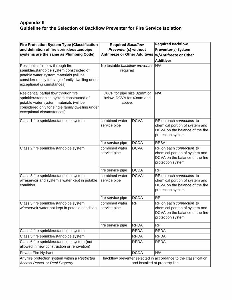
Appendix II
Fire Protection System Type (Classification and definition of fire sprinkler/standpipe systems are the same as Plumbing Code)
Required Backflow Preventer(s) System w/Antifreeze or Other Additives
Residential full flow through fire sprinkler/standpipe system constructed of potable water system materials (will be considered only for single family dwelling under exceptional circumstances)
N/A
Residential partial flow through fire sprinkler/standpipe system constructed of potable water system materials (will be considered only for single family dwelling under exceptional circumstances)
N/A
combined water service pipe
DCVA RP on each connection to chemical portion of system and DCVA on the balance of the fire protection system
fire service pipe DCDA RPBAcombined water service pipe
DCVA RP on each connection to chemical portion of system and DCVA on the balance of the fire protection system
fire service pipe DCDA RPcombined water service pipe
DCVA RP on each connection to chemical portion of system and DCVA on the balance of the fire protection system
fire service pipe DCDA RPcombined water service pipe
RP RP on each connection to chemical portion of system and DCVA on the balance of the fire protection system
fire service pipe RPDA RPClass 4 fire sprinkler/standpipe system RPDA RPDAClass 5 fire sprinkler/standpipe system RPDA RPDAClass 6 fire sprinkler/standpipe system (not allowed in new construction or renovation)
RPDA RPDA
Private Fire Hydrant DCDA N/AAny fire protection system within a Restricted Access Parcel or Real Property
backflow preventer selected in accordance to the classification and installed at property line
Guideline for the Selection of Backflow Preventer for Fire Service Isolation
Class 2 fire sprinkler/standpipe system
Class 3 fire sprinkler/standpipe system w/reservoir and system’s water kept in potable condition
Class 3 fire sprinkler/standpipe system w/reservoir water not kept in potable condition
Class 1 fire sprinkler/standpipe system
Required Backflow Preventer (s) without
Antifreeze or Other Additives
No testable backflow preventer required
DuCF for pipe size 32mm or below, DCVA for 40mm and
above.

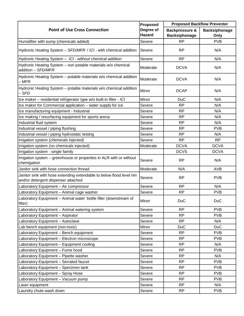
Appendix III
Backpressure & Backsiphonage
Backsiphonage Only
Acid wash or hot tank Severe RP PVBAgricultural chemical sprayer - ICI Severe RP PVBAir compressor commercial/industrial, no chemical added Moderate DCVA N/AAir compressor oil cooler - see heat exchanger & temperature above 60° C Moderate DCVA N/A
Air compressor oil cooler - see heat exchanger & temperature above 60° C Severe RP N/A
Air conditioning systems - no chemical added Moderate DCVA N/AAir conditioning systems Severe RP N/AAir washer Severe RP N/AAnimal cage washer Severe RP PVBAnimal wash Severe RP PVBAnimal watering Severe RP PVBAquarium make up Severe RP PVBAspirator – MFR / ICI Severe RP PVBAspirator - SFD Minor DuC or HCDVB HCVB Aspirator - Vault drain Severe RP PVBAutoclave Severe RP N/AAutopsy/mortuary equipment Severe RP PVBAuxiliary water Severe AG AGBaptismal fountain Moderate DCVA AVBBathtub deck mount faucet w/flex hose SFD / MFR Minor DuC DuCBattery fill connection - permanent or hose bibb Severe RP PVBBeverage dispenser – non carbonated Minor DuC AVB Beverage dispenser hose & head w/carbonated beverages and water Severe RP N/A
Bidet Severe N/A AVB Boiler / steam generation w/o chemical addition Moderate DCVA N/ABoiler / steam generation with chemical addition Severe RP N/ABoosted water temperature above 65° C inlet to booster and water inlet < 13mm with chemical addition Severe RP N/A
Boosted water temperature above 65° C inlet to booster and water inlet < 13mm and all SFD w/o chemical addition Minor DuC N/A
Boosted water temperature above 65° C inlet to booster and water inlet =/> 13mm with chemical addition Severe RP N/A
Boosted water temperature above 65° C inlet to booster and water inlet =/> 13mm and ICI/MF w/o chemical addition Moderate DCVA N/A
Bottle washer Severe RP N/ABread making equipment w/o steam Minor DuC DuCBread making equipment with steam Moderate DCVA N/A
Proposed Backflow PreventerProposed Degree of Hazard
Point of Use Cross Connection
Guideline for the Selection of Backflow Preventer for Point of Use Isolation

Backpressure & Backsiphonage
Backsiphonage Only
Proposed Backflow PreventerProposed Degree of Hazard
Point of Use Cross Connection
Brewery equipment Severe RP N/ABrine tank Moderate DCVA AVB Can washer Severe RP PVBCar / Truck washing equipment Severe RP N/ACO2 injection Severe RP N/ACart washer Severe RP N/AChemical cleaning tank Severe RP PVBChemical feed system, separate or integral to another equipment/appliance Severe RP PVB
Chemical feed/mixing vessel Severe RP PVBChemical holding/storage tank Severe RP PVBChilled water system / chiller tank (closed, no chemical) Moderate DCVA DCVAChilled water system / chiller tank (open, or with chemical) Severe RP PVBChilled water system / chiller tank Severe RP PVBChlorinator Severe RP PVBCircuit Board Washer Severe RP PVBClothes washer – single residential type – MFR – Commercial Minor DuC DuCClothes washer or laundry machines – bank of multiple machines – MFR – Commercial (coin operated) Moderate DCVA PVB
Clothes washer and laundry machines - Industrial (other than coin-operated washer) Severe RP PVB
Commercial Kitchen Equipment – Coffee brewer / urn Minor DuC N/A
Commercial Kitchen Equipment – Commercial dish or ware washer Severe RP PVB
Commercial Kitchen Equipment – Cooking Kettle Minor DuC DuC
Commercial Kitchen Equipment – Cappuccino / Espresso Machine Moderate DCVA N/A
Commercial Kitchen Equipment – Dipper well Moderate DCVA AVB
Commercial Kitchen Equipment – Dish rinse unit with flexible hose Moderate DCVA AVB
Commercial Kitchen Equipment – Dish/pot rinse flex hose (hose extendable to below flood level rim) Severe RP PVB
Commercial Kitchen Equipment – Food steamer Moderate DCVA N/ACommercial Kitchen Equipment – Hot chocolate maker Minor DuC N/ACommercial Kitchen Equipment – Hot water dispenser water Minor DuC N/ACommercial Kitchen Equipment – Glass washer Severe RP PVBCommercial Kitchen Equipment – Ice cream / custard machine Moderate DCVA AVB Commercial Kitchen Equipment – Ice machine– water feed Severe RP N/ACommercial Kitchen Equipment – Ice machine– condenser cooling (exchanger not DWLP) Severe RP N/A
Commercial Kitchen Equipment – Juice machine Minor DuC DuCCommercial Kitchen Equipment – Range/vent hood or canopy wash down Severe RP PVB
Commercial Kitchen Equipment – Rotisserie oven Moderate DCVA N/A

Backpressure & Backsiphonage
Backsiphonage Only
Proposed Backflow PreventerProposed Degree of Hazard
Point of Use Cross Connection
Commercial Kitchen Equipment – Pot washer Severe RP N/ACommercial Kitchen Equipment – Potato peeler Moderate DCVA AVB Commercial Kitchen Equipment – Steam cooker Moderate DCVA N/ACommercial Kitchen Equipment – Steam table Moderate DCVA AVB Commercial Kitchen Equipment – Steamer Oven Moderate DCVA N/ACommercial Kitchen Equipment – Tea maker water Minor DuC N/ACommercial Kitchen Equipment - Waste food tray line/trough Severe RP PVBCommercial Kitchen Equipment – Waste pulper Severe RP PVBCommercial Kitchen Equipment – Waste pulp press Severe RP PVB
Commercial Kitchen Equipment – Wok table with submerged inlet Moderate DCVA AVB
Computer cooling Severe RP N/AConcrete coring machine Moderate DCVA AVB Concrete Mixing Severe RP PVBCondensate cooling/receiver/tank Severe RP N/ACondenate tank (top feed) Moderate DCVA AVB Conveyor washer Severe RP PVBCooling condenser, AC unit (solenoid downstream) Severe RP PVBCooling condenser, AC unit (solenoid upstream) Minor DuC DuCCooling tower Severe RP N/ADairy Processing Severe RP PVBDe-aerator (bottom feed) Severe RP N/ADe-aerator (top feed) Moderate DCVA N/ADegreasing equipment Severe RP PVBDental Equipment – Cuspidor Severe RP PVBDental Equipment – Water supply to each dental chair Severe RP PVBDental Equipment – Film processor Severe RP PVBDental Equipment – Model Trimmer Severe RP PVBDental Equipment – Sterilizer Severe RP N/ADental Equipment – Vacuum pump Severe RP PVBDental Equipment – X ray machine Severe RP PVBDescaling equipment Severe RP PVBDetergent/Soap dispenser Severe RP PVBDishwasher (commercial) Moderate DCVA N/ADishwasher ( MF - residential) Moderate DCVA N/ADishwasher – single residential type Minor DuC N/ADisinfection Equipment – Mobile hazmat/other Severe RP PVBDistiller Minor DuC DuCDockside connection to each pleasure craft and small commercial boat Severe RP RP
Dockside connection to each large commercial vessel Severe RP RPDrinking fountain in park (human or animal) Moderate DCVA DCVADry cleaning equipment Severe RP PVBDye vat Severe RP PVB

Backpressure & Backsiphonage
Backsiphonage Only
Proposed Backflow PreventerProposed Degree of Hazard
Point of Use Cross Connection
Dye equipment Severe RP PVBDynamometer Severe RP PVBEmergency eyewash/showerEngine/genset cooling system Severe RP N/AEquipment wash down Severe RP PVBEtching tank Severe RP PVBEvaporative cooler / swamp cooler Severe RP PVBFermentation tank Severe RP PVBFilm processor Severe RP PVBFire engine foam tank fill connection (fire hall) Severe RP PVBFire hose cleaning equipment Severe RP PVBFire hose cabinet (connected to domestic piping) Moderate DCVA N/AFlexible shower hose – SFD Minor DuC DuCFloor drain with flushing rim Severe RP PVBFlush tank – water closet Moderate N/A Anti-siphon deviceFlushing equipment device (not flush valve) Severe RP PVBFossil fuel tank/equipment Severe RP PVBFountain, ornamental (water feature), indoor Moderate DCVA AVB Fountain, ornamental (water feature), outdoor Severe RP PVBFountain, ornamental (water feature) (chemicals added) Severe RP PVBFreeze thaw machine with antifreeze Severe RP PVBFreeze thaw machine Moderate DCVA PVBFrozen carbonated beverage maker – condenser cooling Severe RP N/AFume hood Severe RP PVBGarbage can washer Severe RP PVBGarbage chute wash down Severe RP PVBGarbage disposal unit Severe RP PVBGas station customer water kiosk/hose connection Moderate DCVA N/AGeothermal heat recovery system/heat pump Severe RP N/AGolf ball/club washer w/o chemical addition Moderate DCVA AVBGolf ball/club washer w/ chemical addition Severe RP PVBHeating system SFD (no chemicals added) Minor DCAP N/AHelipad connections Severe RP N/AHose connection – ICI minor hazard process Minor DuC HCVBHose connection – ICI moderate hazard process Moderate DCVA AVBHose connection – ICI severe hazard process Severe RP PVBHospital (active treatment area) Severe RP PVBHospital (non-treatment area) Moderate DCVA AVBHot press cooling Severe RP N/AHot tub/Spa, Commercial, – Direct Feed Severe RP PVBHot tub/Spa, MF, – Direct Feed, no chemical Moderate DCVA DCVAHot tub/Spa, SFD, – Direct Feed Minor DuC DuCHumidifier – SFD Minor DuC DuCHumidifier Moderate DCVA DCVA
Install upstream of the zone isolation
Backpressure & Backsiphonage
Backsiphonage Only
Proposed Backflow PreventerProposed Degree of Hazard
Point of Use Cross Connection
Humidifier with sump (chemicals added) Severe RP PVB
Hydronic Heating System – SFD/MFR / ICI - with chemical addition Severe RP N/A
Hydronic Heating System – ICI - without chemical addition Severe RP N/AHydronic Heating System – non potable materials w/o chemical addition – SFD/MFR Moderate DCVA N/A
Hydronic Heating System – potable materials w/o chemical addition – MFR Moderate DCVA N/A
Hydronic Heating System – potable materials w/o chemical addition – SFD Minor DCAP N/A
Ice maker – residential refrigerator type w/o built-in filter - ICI Minor DuC N/AIce maker for Commercial application – water supply for ice Severe RP N/AIce manufacturing equipment - Industrial Severe RP N/AIce making / resurfacing equipment for sports arena Severe RP N/AIndustrial fluid system Severe RP N/AIndustrial vessel / piping flushing Severe RP PVBIndustrial vessel / piping hydrostatic testing Severe RP N/AIrrigation system (chemicals injected) Severe RP RPIrrigation system (no chemicals injected) Moderate DCVA DCVAIrrigation system - single family DCVS DCVAIrrigation system – greenhouse or properties in ALR with or without chemigation Severe RP N/A
Janitor sink with hose connection thread Moderate N/A AVBJanitor sink with hose extending extendable to below flood level rim and/or detergent dispenser attached Severe RP PVB
Laboratory Equipment – Air compressor Severe RP N/ALaboratory Equipment – Animal cage washer Severe RP PVBLaboratory Equipment – Animal water bottle filler (downstream of filter) Minor DuC DuC
Laboratory Equipment – Animal watering system Severe RP PVBLaboratory Equipment – Aspirator Severe RP PVBLaboratory Equipment – Autoclave Severe RP N/ALab bench equipment (non-toxic) Minor DuC DuCLaboratory Equipment – Bench equipment Severe RP PVBLaboratory Equipment – Electron microscope Severe RP PVBLaboratory Equipment – Equipment cooling Severe RP N/ALaboratory Equipment – Fume hood Severe RP PVBLaboratory Equipment – Pipette washer Severe RP N/ALaboratory Equipment – Serrated faucet Severe RP PVBLaboratory Equipment – Specimen tank Severe RP PVBLaboratory Equipment – Spray Hose Severe RP PVBLaboratory Equipment – Vacuum pump Severe RP PVBLaser equipment Severe RP N/ALaundry chute wash down Severe RP PVB

Backpressure & Backsiphonage
Backsiphonage Only
Proposed Backflow PreventerProposed Degree of Hazard
Point of Use Cross Connection
Laundry tub with hose bibb connection MFR / ICI Moderate DCVA AVBLens cutting / grinding equipment Severe RP PVBLethal substance Severe RP PVBLivestock equipment Severe RP PVBLubrication pit Severe RP PVBMeat / fish display case Moderate DCVA AVBMedical Equipment – Air compressor Severe RP N/AMedical Equipment – Angio / MRI cooling Severe RP N/AMedical Equipment – Aspirator Severe RP PVBMedical Equipment – Autoclave /sterilizer Severe RP N/AMedical Equipment – Bedpan macerator Severe RP PVBMedical Equipment – Bedpan sprayer Severe RP PVBMedical Equipment – Bedpan washer / sterilizer Severe RP N/AMedical Equipment – Blood analysis equipment Severe RP PVBMedical Equipment – Burn shower Severe RP PVBMedical Equipment – CT scan Severe RP N/AMedical Equipment – Cart washer Severe RP N/AMedical Equipment – Dialysis equipment Severe RP N/AMedical Equipment – Dye slide table Severe RP PVBMedical Equipment – Endoscope Severe RP PVBMedical Equipment – Equipment / instrument decontamination sink & equipment Severe RP PVB
Medical Equipment – Film processor Severe RP PVBMedical Equipment – Hose connection / bibb Severe RP RPMedical Equipment – Hydrotherapy bath Severe RP PVBMedical Equipment – Laser cooling Severe RP N/AMedical Equipment – MRI cooling Severe RP N/AMedical Equipment – Patient tub w/flexible hose Severe RP PVBMedical Equipment – Renal processor Severe RP PVBMedical Equipment – Steris washer Severe RP N/AMedical Equipment – Wash down station Severe RP PVBMedical Equipment – Vacuum pump Severe RP RPMedical Equipment – Ultrasonic washer Severe RP PVBMedical Equipment – X-ray equipment Severe RP RPMobile carpet cleaning equipment Severe RP N/AMixing tee with steam and water Moderate DCVA N/AMortuary or Morgue Severe RP PVBOpticiam or Ophthalmology Equipment Moderate DCVA DCVAPaint booth Severe RP N/AParts washer (not acid wash or hot tank) Severe RP PVBPedicure spa / bowl Severe RP PVBPesticide applicator trucks and equipment Severe RP PVBPhoto developing equipment Severe RP PVBPhoto lab sink / tank Severe RP PVB

Backpressure & Backsiphonage
Backsiphonage Only
Proposed Backflow PreventerProposed Degree of Hazard
Point of Use Cross Connection
Piping to chemical dispensers Severe RP PVBPlating tank Severe RP PVBPoultry barn Severe RP N/APressure washer (no aspirator) Minor DuC N/APressure washer (with aspirator) Severe RP N/APrivate fire hydrant Moderate DCDA N/AProduce / floral misting system Moderate DCVA AVBProofer oven Moderate DCVA N/A
Pump primer line (non-toxic) Not for auxiliary water source pump Moderate DCVA N/A
Pump primer line (toxic) Not for auxiliary water source pump Severe RP N/APump primer line for auxiliary water source pump Severe AG AGRadiator flushing equipment Severe RP PVBRecreational vehicle dump station Severe RP RPRefrigeration unit - industrial Severe RP RPRestricted area Severe RP RPReverse osmosis equipment - SFD w/o chemical cleaning and/or backwashing Minor DuC DuC
Reverse osmosis equipment with chemical cleaning and/or backwashing Severe RP RP
Reverse osmosis equipment - MFR / ICI w/o chemical cleaning and/or backwashing & inlet less than 25mm Moderate DCVA DCVA
Reverse osmosis equipment - MFR / ICI inlet 25mm or greater Moderate RP RPRock drill Severe RP N/ARock polisher Severe RP PVBRock / pavement saw Severe RP PVBSanitary equipment Severe RP PVBService sink w/hose connection thread ICI properties Moderate DCVA AVBService sink w/hose extendable to below flood level rim - industrial properties and properties with severe hazard Severe RP PVB
Sewage ejector Severe RP PVBSewage pump Severe RP N/ASewage lift station standpipe Severe RP N/ASewer connected equipment Severe RP PVBSewer flushing hose / equipment Severe RP N/AShampoo sink Moderate DCVA AVBSilver recovery unit Severe RP PVBSizing vat Severe RP PVBSolar energy unit - SFD with no chemical added, potable piping material Minor DCAP N/A
Solar energy unit - MFR with no chemical added, potable piping material Moderate DCVA N/A
Solar energy unit - SFD/MFR with no chemical added, non-potable piping material Moderate DCVA N/A

Backpressure & Backsiphonage
Backsiphonage Only
Proposed Backflow PreventerProposed Degree of Hazard
Point of Use Cross Connection
Solar energy unit - ICI Severe RP N/ASolar energy unit - chemical added Severe RP N/ASolution tank Severe RP PVBSonic washer Severe RP PVBSolvent recycling equipment Severe RP PVBSolvent washer Severe RP PVBSpecimen tank Severe RP PVBSteam cleaner Moderate DCVA N/ASteam generator (small unit contained within appliance/equipment) – w/o chemical addition Moderate DCVA N/A
Still (water purifier or brewery equipment) minor DuC DuCStorm sewer Severe RP PVBSump Severe RP PVBSwimming pool – Direct feed Moderate DCVA AVBSwimming pool (other than residential) Moderate DCVA AVBSwimming pool makeup tank Moderate DCVA AVBSwimming pool (residential ) Minor DuC DuCTanning booth Severe RP PVBTeeth cleaning equipment (veterinary type) Severe RP PVBTrackside connection to train Severe RP N/ATrap priming connection (Trap primer) Severe RP PVBVacuum pump – ICI Severe RP PVBVending Machine (No carbonater) minor DuC DuCVeterinary equipment – see medical equipment Severe RP PVBWash rack Severe RP PVBWash tank (toxic) Severe RP PVBWashlette Severe RP PVBWaste water treatment process Severe AG AG Water cooled equipment Severe RP N/AWater cooled equipment Severe RP N/AWash down equipment Severe RP PVBWater filter – SFD Minor DuC DuCWater Filter – MFR / ICI filter inlet < 25mm Moderate DCVA DCVAWater filter – MFR / ICI filter inlet 25mm and larger Severe RP PVBWater hauling equipment – other than City approved potable usage equipment Severe RP RP
Water operated equipment (hydraulic) no chemical added (not aspirators/ejectors) Moderate DCVA N/A
Water operated equipment (hydraulic) with chemical added (not aspirators/ejectors) Severe RP N/A
Water softener - SFD Minor DuC N/AWater softener - ICI Severe RP N/AWater softener drain Severe RP PVB

Backpressure & Backsiphonage
Backsiphonage Only
Proposed Backflow PreventerProposed Degree of Hazard
Point of Use Cross Connection
Water treatment (ph balancing) Severe RP N/AWater treatment / filtering and dispensing equipment Severe RP N/AX-ray equipment – ICI Severe RP N/AYard Hydrant – minor to moderate hazard process Moderate DCVA N/AYard Hydrant – severe hazard process Severe RP N/A

U:\P
ro
je
cts_
VA
N\1
07
2\0
19
7\0
1\D
-D
ra
ftin
g-D
esig
n-A
na
lysis\C
AD
\P
LN
-1
07
2-C
RO
SS
-C
ON
EC
TIO
N-C
ON
TR
OL
-D
ET
AIL
S_
MA
Y2
01
4.d
wg
[F
IG
1
] 1
6/0
5/2
01
4 1
0:1
6:3
6 A
M
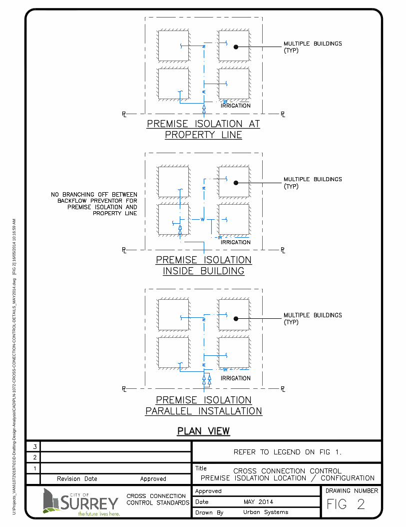
U:\P
ro
je
cts_
VA
N\1
07
2\0
19
7\0
1\D
-D
ra
ftin
g-D
esig
n-A
na
lysis\C
AD
\P
LN
-1
07
2-C
RO
SS
-C
ON
EC
TIO
N-C
ON
TR
OL
-D
ET
AIL
S_
MA
Y2
01
4.d
wg
[F
IG
2
] 1
6/0
5/2
01
4 1
0:1
6:5
9 A
M
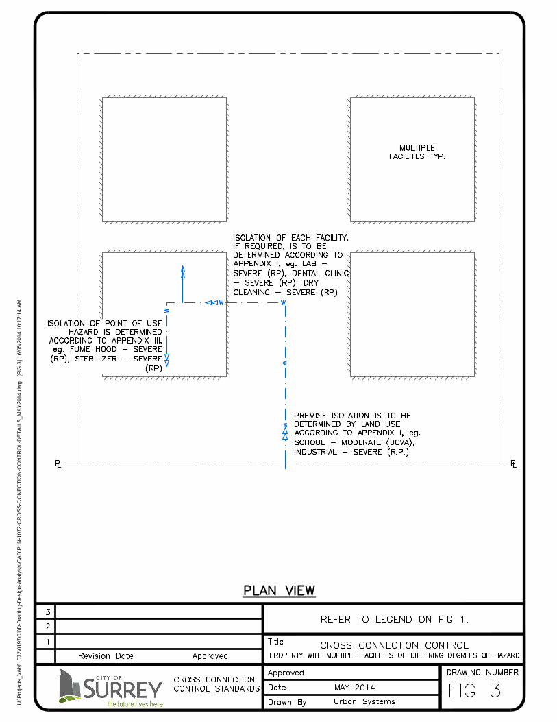
U:\P
ro
je
cts_
VA
N\1
07
2\0
19
7\0
1\D
-D
ra
ftin
g-D
esig
n-A
na
lysis\C
AD
\P
LN
-1
07
2-C
RO
SS
-C
ON
EC
TIO
N-C
ON
TR
OL
-D
ET
AIL
S_
MA
Y2
01
4.d
wg
[F
IG
3
] 1
6/0
5/2
01
4 1
0:1
7:1
4 A
M