cross connection control policy
TRANSCRIPT

Cross Connection Control Policy
Date of Last Revision: March 19, 2015

1
Policy on Cross-Connections OUC agrees with the American Water Works Association’s (AWWA) statement issued on cross connection as follows: A statement adopted by Board of Directors of the American Water Works Association on Jan.26, 1970, revised June 24, 1979 and reaffirmed June 10, 1984 and revised Jan 28, 1990 and Jan.21, 2001 as follows:
The American Water Works Association recognizes that the water purveyor has a responsibility to provide its customers at the service connection with water that is safe under all foreseeable circumstances. Thus, in the exercise of this responsibility the water purveyor must take reasonable precaution to protect the community distribution system from the hazards originating on the premises of its customers that may degrade the water in the community distribution system. Cross-connection control and plumbing inspections on premises of its customers are regulatory in nature and should be handled through the rules, regulations, and recommendations of the health authority or the plumbing code enforcing agencies having jurisdiction. The water purveyor, however, should be aware of any situation requiring inspection and/or re-inspections, necessary to detect hazardous conditions resulting from cross-connections. If, in the opinion of the utility, effective measures consistent with the degree of hazard have not been taken by the regulatory agency, the water purveyor should take such measures as it may deem necessary to ensure that the community distribution system is protected from contamination. Such action would include the testing or installation of a backflow prevention device, consistent with the degree of hazard, at the service connection or discontinuance of the service. In addition, customer use of water from the community distribution system for cooling or other purposes within the customer's system and later return of the water to the community distribution system is not acceptable and is opposed by AWWA.

2
Introduction A cross-connection is defined in the rules of the Department of Environmental Protection (DEP),of the State of Florida, Chapter 62-550 of the Florida Administrative Code (FAC) as follows:
Any physical arrangement whereby a public water supply is connected, directly or indirectly with any other water supply system, sewer, drain, conduit, pool, storage reservoir, plumbing fixture, or other device which contains or may contain contaminated water, sewage and other waste or liquid of unknown or unsafe quality which may be capable of imparting contamination to the public water supply as the result of backflow. By-pass arrangements, jumper connections, removable sections, swivel or changeable devices and other temporary or permanent devices through which or because of which backflow could occur are considered to be cross connections.
Consequently, either cross-connection or the chance of backflow must be eliminated to prevent degrading the high quality of water that water purveyors strive to maintain. Initially, the primary responsibility for safeguarding water quality on private property, eliminating cross connections and preventing backflow, was left to local health agencies and building and inspection departments. Then, beginning with the Safe Drinking Water Act, signed by President Ford on December 16, 1974, a chain of laws and regulation evolved that resulted in the State requirement (Florida Safe Drinking Water Act, Sections 403.850-403.864, Florida Statues) for all the public water systems to have a cross-connection control program contained within the Rules of Department of Environmental Protection (DEP), Chapter 62-555, FAC, State of Florida, on January 3,1991, amended August 28, 2003, adopted the following policy: Community water systems, and all public water systems that have service areas also served by reclaimed water systems regulated under Part III of Chapter 62-610, F.A.C., shall establish and implement a routine cross-connection control program to detect and control cross-connections and prevent backflow of contaminants into the water system. This program shall include a written plan that is developed using recommended practices of the American Water Works Association set forth in Recommended Practice for Backflow Prevention and Cross-Connection Control, AWWA Manual M14, as incorporated into Rule 62-555.330(2), F.A.C.

3
Upon discovery of a prohibited cross-connection, public water systems shall either eliminate the cross-connection by installation of an appropriate backflow prevention device acceptable to the Department or shall discontinue service until the contaminant source is eliminated. Chapter 62-555.360(3), F.A.C. In compliance with this mandate, the following is OUC’s Policy on Cross-Connection Control. We urge you to acquaint yourself with the policies and information presented in this manual. It is only through the education and commitment of persons like yourself that we can control the hazards presented by cross connections within our public drinking water supply. OUC supports this policy and its enforcement and will offer its assistance to all who share the responsibility providing and maintaining safe drinking water.

4
Chapter I Overview 1.01 Purpose The purpose of this Policy is to protect OUC’s public potable water supply from the possibility of contamination. This policy is to promote the elimination or control of existing cross-connections, actual or potential, between its customers' in-plant plumbing fixtures and industrial piping and the public water supply; and to provide for the maintenance of a continuing program of cross-connection control which will systematically and effectively prevent the contamination of the potable water distribution system. More exactly, the Policy is intended to prevent delivered water (water that has passed beyond the public water system and into the private distribution systems of customers) from re-entering the public distribution system and being subsequently delivered to customers. This allows persons active in piping design and installation to incorporate and install appropriate backflow prevention assemblies correctly. 1.02 Causes of Backflow The causes of backflow are not usually eliminated completely since backflow is often initiated by accident or unexpected circumstances. However, some causes of backflow can be partially controlled by good design and informed maintenance. Listed below are the major causes of backflow as outlined under the two types: backsiphonage and backpressure. 1. Backsiphonage - is caused by reduced or negative pressure being created in the supply piping. The principal causes of backsiphonage are:
a. Line repair or break which is lower than a service point. This will allow negative pressures to be created by water trying to flow to a lower point in the system.
b. Undersized piping - if water is withdrawn from a pipe at a very high velocity, the pressure in the pipe is reduced and the pressure differential created can cause water to flow into the pipe from a contaminated source.
c. Lowered pressure in water main due to high water withdrawal rate such as fire fighting, water main flushing, or water main breaks.
d. Reduced main pressure on suction side of a booster pump.

5
2. Backpressure - may cause backflow to occur where a potable water system is connected to a non-potable system of piping, and the pressure in the non-potable system exceeds that in the potable system. The principal causes of back pressure are:
a. Booster pump systems designed without backflow prevention assemblies.
b. Potable water connections to boilers and other pressure systems without backflow prevention assemblies.
c. Connections with another system which may at times have a higher pressure.
d. Water stored in tanks or plumbing systems which, by virtue of their elevation, would create head pressures sufficient to cause backflow if pressure were lowered in the public system.

6
Chapter II Responsibilities
2.01 Cross-Connection Program The responsibilities of OUC’s cross-connection control program in accordance with State Law Chapter 62-555, FAC are as follows: 1. To protect OUC’s Public Water Supply from the possibility of contamination by isolating within the customers' private water systems, contaminants or pollutants which could, under adverse conditions, backflow through uncontrolled cross-connections into the public water system. 2. To eliminate or control existing cross-connections, actual or potential, between the customer’s on site potable water system(s) (i.e. well) and non-potable water system(s) plumbing fixtures, and industrial piping systems. 3. To provide a continuing inspection program, of cross-connection control, which will systematically and effectively control all actual or potential cross-connecting which may be installed in the future. 2.02 Customers The customers’ responsibility starts at the point of delivery from the public potable water system and includes all of their water systems. The customer, at their own expense, shall install, operate, test and maintain approved backflow prevention assemblies, as directed by OUC. The customer shall maintain accurate records of tests and repairs made to backflow prevention assemblies and provide OUC with copies of such records. The records shall be on forms approved by OUC. In event of accidental pollution or contamination of the public or customers’ potable water system due to backflow on or from customer's premises, the owner shall promptly take steps to confine further spread of pollution or contamination within the customers’ premises, and shall immediately notify OUC of the hazard.
7
2.03 Backflow Prevention Assembly Installers The installers’ responsibility, after acquiring a permit through the proper regulatory agency, is to make proper installation of backflow prevention assemblies in accordance with the manufacturers’ installation instructions and any additional instructions approved by OUC. All backflow devices shall be installed adjacent to the right-of-way on private property within three feet (3’) of the water meter, unless otherwise approved by OUC. The installer is also responsible to make sure an assembly is working properly when it is installed, and is required to furnish the following information to OUC’s Water Distribution Section immediately after a Reduced Pressure Detector Assembly (RPDA), Reduced Pressure Principle Backflow Preventer (RPZ), Double Check Valve Assembly (DC) (1 inch maximum in residential reclaimed areas), is installed:
1. Service address and zip code where device is located 2. Owner, Contact Phone #, and OUC account # 3. Description of device's location and meter # 4. Date of installation 5. Type of device 6. Manufacturer 7. Model number 8. Serial number 9. Size of device
All backflow preventers are required to be tested following installation by an FW&PCOA or UF TREEO approved certified backflow assembly tester.

8
Chapter III Inspections
3.01 Frequency Due to changes in models or components of equipment, methods of manufacturing and additions to plants, buildings, etc., water use requirements undergo continual change. New cross-connections may be installed and existing protection may be by-passed, removed, or become otherwise ineffective; therefore, a periodic site inspection by OUC may be required at the time of the backflow test. For premises where reclaimed water is available, OUC, the City of Orlando, or Orange County may perform site inspections. These inspections will be on the customer’s premises and may consist of, but are not limited to:
1. Notifying customer of site inspection 2. Visual check for Cross-connection 3. Test potable water for signs of reclaimed water 4. Verify backflow device is installed and working properly 5. Physical check of all outside hose connections
The initial inspection will be performed by the City of Orlando or Orange County when the reclaimed water meter is installed and connected to the irrigation system. Periodic inspections may be performed by OUC, the City of Orlando or Orange County. A site inspection may also be performed when the reclaimed service is turned on in a new customers name or when the service status changes to active. 3.02 Proposed Constructions All new construction plans and specifications for commercial facilities shall be reviewed by OUC’s Water Business Unit to determine the degree of potential cross-connection hazard. At this time, backflow prevention requirements in accordance with this policy will be made. 3.03 New and Existing Facilities In order to determine the degree of hazard to the public potable water system, a survey will be made of the customers’ presently installed water system. This survey need not be a detailed inspection of the location or disposition of the water mains but can be confined to establishing the water uses on the premises for the existence of cross-connections, and the availability of auxiliary or used water supplies. On site inspections are made of new and existing facilities and should any devices or plumbing change be required, a follow-up inspection will be made of the same facilities at a later date.
9
Chapter IV Cross-Connection Hazards and Required
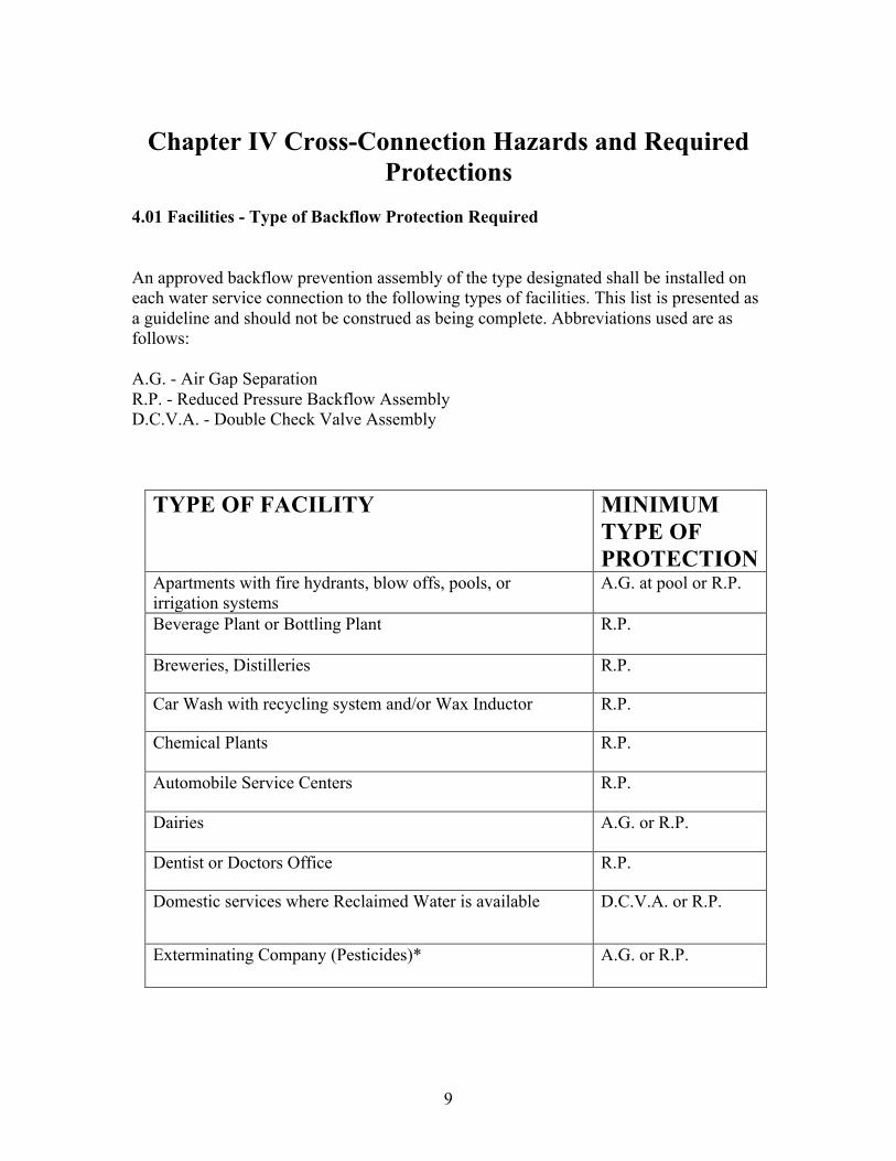
Protections 4.01 Facilities - Type of Backflow Protection Required An approved backflow prevention assembly of the type designated shall be installed on each water service connection to the following types of facilities. This list is presented as a guideline and should not be construed as being complete. Abbreviations used are as follows: A.G. - Air Gap Separation R.P. - Reduced Pressure Backflow Assembly D.C.V.A. - Double Check Valve Assembly
TYPE OF FACILITY MINIMUM TYPE OF PROTECTION
Apartments with fire hydrants, blow offs, pools, or irrigation systems
A.G. at pool or R.P.
Beverage Plant or Bottling Plant R.P.
Breweries, Distilleries R.P.
Car Wash with recycling system and/or Wax Inductor R.P.
Chemical Plants R.P.
Automobile Service Centers R.P.
Dairies A.G. or R.P.
Dentist or Doctors Office R.P.
Domestic services where Reclaimed Water is available D.C.V.A. or R.P.
Exterminating Company (Pesticides)* A.G. or R.P.

10
TYPE OF FACILITY
MINIMUM TYPE OF PROTECTION
Fertilizer Plants
R.P.
Film Laboratory or Processing Plant
R.P.
Hospitals, Clinics, Medical Facilities
R.P. (Parallel)
Hotels and Motels
R.P.
Commercial Irrigation Systems with elevated or pop-up sprinkler heads
R.P.
Irrigation Systems with chemical injectors
R.P.
Laundries, Dry Cleaning, or Dye Works
R.P.
Laundromats
R.P.
Machine Tool Plants
R.P.
Master Metered Strip Shops
R.P.
Metal Plating Plant
R.P.
Mobile Home/Travel Trailer Parks with fire hydrants, blow offs, pools, or irrigation systems.
A.G. or R.P.
Morgues or Mortuaries
R.P.
Nursing Homes
R.P.
Packing Houses or Rendering Plants
R.P.
Paper Products Plant
R.P.
Parks/Recreational Facilities with fire hydrants, blow offs, pools, or irrigation systems.
A.G. or R.P.
Petroleum Processing Plant
R.P.
Petroleum Storage Plant
R.P.

11
Pharmaceutical or Cosmetic Plant Piers, Docks or Waterfront Facilities
R.P.
Power Plants
R.P.
Radioactive Material Plants
R.P.
Restaurants with Soap Inductors and/or Industrial Type Disposal
R.P.
Sand and Gravel Plants
R.P.
Schools
R.P.
Swimming Pools with Piped Fill Line
A.G. at pool or R.P.
Sewage Treatment Plants
R.P.
Sewage Pumping Stations
R.P.
Storm Water Pumping Station R.P.
Tall Buildings over three stories R.P.
Veterinary Establishments R.P.
*Exterminating Companies-All tanks, tank trucks, and spraying apparatus used to convey pesticides in an exterminating process are required to use only designated-protected potable water fill locations. Filling with potable water at unspecified locations or private residences is prohibited. All filling locations will consist of overhead piping arrangements with correctly installed air-gap. If, for any reason, an overhead piping arrangement cannot be used, a reduced pressure zone backflow assembly must be installed on the fill line. All filling locations must be inspected and approved by OUC prior to being put into service.

12
In addition to and including those types of facilities listed above, an approved backflow prevention assembly of the type designated shall be installed on each domestic water service connection to any premises containing the following real or potential hazards.
MINIMUM TYPE OF PROTECTION
Premises having an auxiliary water system not connected to public water system
R.P.
Premises having a water storage tank, reservoir, pond, or similar appurtenance
R.P.
Premises having a steam boiler, cooling system, or hot water heating system where chemical water conditioners are use
R.P.
Premises having submerged inlets to equipment
R.P.
Premises having self-draining yard hydrants, fountains, hose boxes or similar devices presenting a health or system hazard(i.e., chemical storage plants ,tank farms, bulk storage yards)
R.P.
Premises having self-draining yard hydrants, fountains, hose boxes or similar devices presenting a pollution hazard (i.e., parks, play fields, cemeteries)
R.P.
Premises that have Reclaimed Water available for irrigation or other uses.*
D.C.V.A. or R.P.
Others specified by OUC

13
4.02 Installations Requiring Continuous Service: Parallel Installation All backflow prevention assemblies with test cocks are required to be tested annually. Testing requires a water shutdown usually lasting five (5) to twenty (20) minutes. For facilities that require an uninterrupted supply of water, and when it is not possible to provide water service from two separate meters, provisions shall be made for a "parallel installation" of backflow prevention assemblies. Multi-story buildings which have a number of flush-o-meter toilets should be equipped with parallel assemblies. Experience has shown if the water supply is shut off to this type of building, flush-o-meters may have to be manually reset. During testing, one assembly is left on while the other is being tested. Usually the two assemblies are sized one device size smaller than the service line, e.g. one 2-inch device or two 1½-inch devices, one 8- inch device or two 6-inch devices. OUC will not accept an unprotected bypass around a backflow assembly when the assembly is in need of testing, repair, or replacement. 4.03 Type of Backflow Protection Required - Fire Protection Services An approved reduced pressure backflow preventer with a detector assembly shall be installed on each fire protection service to any premises where a fire protection system is required. 4.04 Other Cross-Connection Hazards 1.Fixture Inlets (or Valved Outlets) with hose attachments, which may constitute a cross-connection, shall be protected by the proper approved devices as required by local state, city and county ordinances. 2.Air condition Cooling Tower – Shall have an RP installed at the customers point of service or the appropriate air gap. 3.Aspirators and Ejectors - Shall have an RP installed at the customers point of service. . 4.Booster Pumps - Shall not be interconnected unless the public supply is protected by an RP at the customers point of service. 5.Private Wells - Shall not be interconnected unless the public supply is protected by an RP at the customers point of service. 6.Portable Spray and Cleaning Equipment - Any portable pressure spray or cleaning units that have the capability of connecting to any potable water supply and do not contain a built-in approved air gap, shall be fitted with a reduced pressure backflow assembly at the filling connection.

14
7. Miscellaneous uses of Water from Fire Hydrants - The operation of fire hydrants by persons other than authorized personnel is prohibited. Portable fire hydrant meters shall be issued by OUC for the use of water from a hydrant for construction or other purposes. Portable fire hydrant meters shall be issued for a period of twelve months. At the end of the twelve month period, the meter must be returned to OUC for the purpose of testing and/or repair as needed of the backflow assembly. Failure to return the meter with the backflow assembly within the specified time period may be considered a violation of OUC’s Cross Connection Control Policy resulting in monetary penalties. 8.Vacuum Breakers (vacuum relief valves) designed to prevent collapse or implosion of a heated pressure vessel when being cooled are not acceptable devices for protection against backflow in potable water line. Note: Any device, equipment, or situation not covered by this cross-connection policy, which may constitute a potential health hazard, will be examined for appropriate treatment by OUC. Note: Single check valves will not be accepted as a means of protecting the potable drinking water system and therefore may only be used to prevent backflow which would affect the functioning of a plumbing system as allowed by the regulatory authorities

15
Chapter V Testing of Backflow Devices
It shall be the duty of the customer at any premises where approved backflow assemblies are installed to have thorough inspections and operational tests made at least once a year, or more often in those instances where inspections indicate a need. These inspections and tests shall be at the expense of the customer and be performed by the assembly manufacturers’ representative, by OUC personnel, or by a certified backflow technician. At the customer’s request OUC will provide the testing of a backflow device at the customer’s premise. OUC will provide a cost estimate to the customer prior to the service being performed. The tester shall provide a copy of the backflow inspection report to OUC. Test reports on all backflow assemblies shall be filed with OUC’s, Water Distribution Division.

16
Chapter VI Penalties for Non-Compliance
6.01 Termination of Service A written notification detailing all cross-connections ( actual or potential) found during the inspection will be sent to the owner or authorized agent of the owner of the building or premises, stating that corrections must be made and setting a reasonable time for compliance. Upon failure of the owner or authorized agent of the owner of the building or premises to have defect(s) corrected by the specified time, OUC may elect to terminate the water service to the building or premises. OUC shall cause discontinuance of water service if a required backflow prevention assembly has been bypassed or failed to be tested or properly maintained as required by this policy. OUC shall also cause discontinuance of water service if an air-gap separation system is compromised. In lieu of discontinuance of service, OUC may take action to install, test, repair, or replace a backflow device at the customer’s point of service and bill the customer for all costs associated with the installation, test, repair, or replacement of a backflow prevention device.

17
Chapter VII Backflow Prevention Devices (Illustrated)
7.01. Air-Gap Separation The term air-gap separation shall mean a physical separation between the free flowing discharge end of a potable water supply pipeline and an open or non-pressure receiving vessel. An approved air-gap separation shall be a distance of at least two (2) times the diameter of the supply pipe measured vertically above the top rim of the vessel, with a minimum distance of one (1) inch.

18
7.02 Double Check Valve Assembly
An assembly composed of two single, independently acting, approved check valves, including tightly closing shut-off valves located at each end of the assembly and fitted with properly located test cocks. A check valve that is drip-tight in the normal direction of flow when the inlet pressure is one psi and the outlet pressure is zero. The check valve shall permit no leakage in a direction reverse to the normal flow. The closure element (e.g., clapper) shall be internally weighted or otherwise internally loaded to promote rapid and positive closure and suitable connections for testing.

19
7.03 Double Check Detector Backflow Assembly A specially designed assembly composed of a line-sized approved double check valve assembly with a bypass containing a specific water meter and an approved double check valve assembly. Meter will register very low flows of water up to three gallons per minute and shall show a registration for all rates of flow. This assembly should only be used against a non-health hazard (i.e., pollutant).

20
7.04 Reduced Pressure Backflow Assembly A specially designed assembly composed of a line-sized approved reduced pressure principle backflow prevention assembly that will protect against non-health hazard (i.e., pollutant) or a health hazard (i.e., contaminant).

21

22
Chapter VIII Reclaimed System Served with Potable Water The OUC potable water system currently serves a small portion of the City of Orlando’s reclaimed system with potable water. The purpose of irrigating in this fashion initially was due to the lack of supply of reclaimed water to the area. However, once the supply became available, both agencies agreed to continue the use of potable water to maintain adequate water quality in the region and conserve water in lieu of flushing. The specific neighborhoods receiving irrigation water in this manner are East Park, La Vina, and Randal Park, located in the southeast region of Orlando. In order to ensure proper cross connection control, each connection from the potable system to the reclaimed system is made with a reduced pressure backflow preventer (commonly called a “jumper”). Additionally, the reclaimed system served with potable water is physically disconnected from the proper reclaimed system (served with reclaimed water).The figure below (Exhibit A) depicts the locations of the backflow preventers and the physical disconnections in relation to the OUC potable water and City of Orlando reclaimed water systems. The jumpers are temporary. The reclaimed system in this area will eventually be served with reclaimed water pending the potable water demand in Randal Park as it continues to buildout. Note that at the time of publication of this document, Randal Park was still under construction and the jumper is therefore subject to change.

23
REFERENCES “Accepted Procedure and Practice in Cross-Connection Control”, Pacific Northwest Section, AWWA, 1973, 1985, 1990, Cincinnati Water Works - Division L-“Cross-Connection Control and Water Quality Protection”, Cincinnati, Ohio November 18, 1974. “Cross-Connections and Backflow Prevention”, AWWA, 1974. “Cross-Connection Control Manual”, Division of Sanitary Engineering, Tennessee Department of Public Health' 1975. “Cross-Connection Control Manual”, U.S. Environmental Protection Agency, Washington, D.C., 1973, 1989, 2003. “Cross-Connection Control Manual”, “Manual of Cross-Connection Control Policies”, Tampa Water Department, Tampa, Florida, June 1981. Public Law 93 -523, “Safe Drinking Water Act”, - 16, 1974. “Recommended Practice for Backflow Prevention and Cross-Connection Control”, AWWA Manual Ml 4, 1960, 1990, 2004 “Rules of the Department of Environmental Protection, F.A.C. chapter 62-550 and 62-555, State of Florida- Department of Environmental Protection”, Water Supplies Standard Building Code 2001, Revisions

24