critique of macro flow/damage surface representations for ... · pdf filecritique of macro...
TRANSCRIPT

NASA Technical Memorandum 107321
! ¢ . j
/"_ . ,. Z/:
Critique of Macro Flow/Damage Surface
Representations for Metal Matrix Composites
Using Micromechanics
Cliff J. Lissenden
Pennsylvania State University
University Park, Pennsylvania
and
Steven M. Arnold
Lewis Research Center
Cleveland, Ohio
Prepared for theInternational Mechanics Engineering Congress and Exposition
sponsored by the American Society of Mechanical Engineers
Atlanta, Georgia, November 17-22, 1996
National Aeronautics and
Space Adminis_'ation
https://ntrs.nasa.gov/search.jsp?R=19970003006 2018-05-23T08:09:00+00:00Z

CRITIQUE OF MACRO FLOW/DAMAGE SURFACE REPRESENTATIONS FORMETAL MATRIX COMPOSITES USING MICROMECHANICS
Cliff J. Lissenden
Department of Engineering Science and MechanicsPenn State University
University Park, PA 16802
Steven M. Arnold
Structural Fatigue BranchNASA Lewis Research Center
Cleveland, OH 44135
ABSTRACT
Guidance for the formulation of robust, multiaxial, constitutive models for advanced materials
is provided by addressing theoretical and experimental issues using micromechanics. The
multiaxial response of metal matrix composites, depicted in terms of macro flow/damage
surfaces, is predicted at room and elevated temperatures using an analytical micromechanical
model that includes viscoplastic matrix response as well as fiber-matrix debonding. Macro
flow/damage surfaces (i.e., debonding envelopes, matrix threshold surfaces, macro "yield"
surfaces, surfaces of constant inelastic strain rate, and surfaces of constant dissipation rate) are
determined for silicon carbide/titanium in three stress spaces. Residual stresses are shown to
offset the centers of the flow/damage surfaces from the origin and their shape is significantly
altered by debonding. The results indicate which type of flow/damage surfaces should be
characterized and what loadings applied to provide the most meaningful experimental data for
guiding theoretical model development and verification.
INTRODUCTION/BACKGROUND
Aerospace structural components are commonly subjected to thermomechanical service
conditions, involving multiple temperature levels, thermal transients and mechanical loads,
severe enough to result in significant nonlinear (e.g., inelastic or damage induced) deformation.
The accurate prediction of the stress, strain and temperature fields within these structural
components depends strongly upon accurate mathematical representations (constitutive
equations) of the nonlinear behavior of structural materials (e.g., monolithic alloys or advanced
composite systems) at high temperature. To be generally applicable, these constitutive equations
must be expressed in multiaxial form and be appropriate for all anticipated modes of mechanical
and thermal loading (e.g., cyclic, nonisothermal, nonproportional, etc.). This is an imposing task,
nevertheless significant advancement has been achieved over the past two decades with the
adventof unified viscoplasticconstitutivemodels(e.g.,Walker (1981),Bodner(1987),Hellingand Miller (1987), Robinson and Duffy (1990), Freed and Walker (1995), Arnold et al.(1996a,b)).Historically, with theexceptionof Spencer(1972),uniaxialconstitutiveresponsehasbeenthefocal point of researchon anisotropicmaterials. Recently,attentionhasbeing focusedon describingthemultiaxial constitutivebehavior(e.g.,RobinsonandDuffy (1990),andSaleeband Wilt (1993)), for new generationsof advancedstructuralmaterials that possessstrongdirectionalcharacteristics(e.g., directionally solidified metals,metal and intermetallic matrixcompositesas well as ceramicand polymeric composites).Suchadvancedmaterialsoffer thedesignerthe additionaladvantageof tailoring his designto haveincreasedstrength,stiffness,conductivity and the like in one or more preferred directions. Under high temperaturethermomechanicalservice conditions these advancedmaterials still exhibit all the time-dependenthereditarybehaviorof moreconventionalalloysbut now their directionalnatureaddsyet another level of complexity. Consequently,the further developmentand validation ofmultiaxial viscoplastic models for metal matrix compositesis essential if these advancedmaterialsareto beutilizedby theaerospaceandpowergenerationindustries.
A key ingredient in the formulationof robust,multiaxial, constitutivemodels is the closeinteractionbetweenexperimentalistsandtheoreticiansin establishingtherequireddevelopmentalprogram.Threetypesof experimentation(Robinson(1985))arenecessaryto supporttherationalformulation of constitutive models for high temperaturestructuralmaterial systems(be theymonolithicor composite).Theseare1)Exploratory tests that guide the development and examine
the fundamental concepts and mathematical constructs embedded in the theoretical framework,
2) Characterization tests that provide the required data base for determining the specific
functional forms and material parameters to represent a particular material over a given range of
conditions, and 3) Verification tests, (often prototypical in nature) that provide the ultimate test
of a constitutive model through comparison of actual structural component response with
analytical predictions based on a given model. As results from these tests should ideally provide
feedback for subsequent developmental efforts, the best verification tests may be those of simple
structures such as beams, plates, shells and bar structures under prototypical conditions of
temperature, stress, strain-rate, etc.
The present work will primarily focus upon practical and theoretical issues relative to
conducting and analyzing tests of the exploration type, i.e., determination of multiaxial
flow/damage surfaces for titanium matrix composites (TMCs). However, it is important to
realize that such exploratory tests on composite materials (which are actually structures) can in
themselves be viewed as verification tests (for both the constitutive model and homogenization
(micromechanics) technique), provided the constitutive equations being verified are developed
utilizing only constituent material properties. This distinction will be developed further within
the body of the report. The necessity of conducting such fundamental multiaxial flow/damage
surface tests can be best understood in the context of classical plasticity; in as much as the
concept of a yield surface plays a central role in that it delineates the elastic and inelastic
deformation regions of the material. The existence and description of this yield surface is
precisely that which allows a consistent multiaxial statement of plastic flow (flow law) to be
written. Mathematically, this is done by making use of the fundamental assumption that the yield
surface has the properties of a potential (normality), e.g.
f(tYij,aq,T) = k

and thus leads to an associated form of the flow law through differentiation of f, that is
delj= °3f_gcrij
where, cro, o_ij, E.Ij, T, and k are the applied Cauchy stress, back (internal) stress and inelastic
strain tensors, temperature and yield stress, respectively.
Experimentally, yield surfaces are typically mapped out using an equivalent inelastic strain
definition and a rather arbitrary target value of permanent set. The impact of the magnitude of
this target value will be indicated subsequently. Multiaxial testing alone provides a quantitative
description off, thereby allowing a correct mathematical form of the flow law to be deduced. To
date significant testing has been done in support of the concept of a yield surface and the
normality condition, albeit at relatively low temperatures and for monolithic materials (e.g.
Phillips (1974), Liu and Greenstreet (1976), Ellis et al. (1978) and Oytana et al. (1982)). Note, as
we are concerned here with primarily examining composite materials, "yield" will be defined to
have occurred whenever deviation from proportionality (DFP) has been exceeded by a specified
target value. In this way the inelastic response can encompass both matrix inelasticity and
internal damage resulting from fiber-matrix debonding.
At elevated temperatures, metallic alloys and TMCs typically exhibit strong time-dependent
deformation behavior and the concept of a yield surface, in the classical sense, generally breaks
down as we move into the realm of viscoplasticity. However, analogous geometrical and
thermodynamically based concepts such as surfaces of constant inelastic strain rate (SCISRs) and
surfaces of constant dissipation rate (SCDRs) t can and have been postulated to play the same
central role in viscoplastic constitutive theories as yield surfaces do in classical plasticity. In fact,
given a complete (i.e., fully associative) potential based framework, as that proposed by Arnold
and Saleeb (1994), the experimental multiaxial identification of the Gibbs and dissipation
potential would completely define the ensuing compliance operator and flow and evolution laws
for the inelastic strain and internal state variables, respectively. This fundamental approach to
the formulation of a consistent multiaxial theory is in stark contrast to the more typical ad hoc
and generally inadequate approach of extending uniaxial constitutive theories for multiaxial
conditions by simply placing bars over the pertinent variables and declaring them "effective"
values. This systematic approach becomes even more important when one deals with materials
that have preferred directions (e.g. TMCs), as the anisotropy and potential for internal damage
(i.e., since debonding is prevalent in TMCs, where it can occur prior to plastic flow in the matrix)
further complicates the shapes of these surfaces in various stress spaces. Many researchers have
documented the effects of debonding on the overall deformation response of TMCs (e.g.,
Johnson et al. (1990), Jansson et al. (1991), Majumdar and Newaz (1992), Lerch and Saltsman
(1993), Lissenden et al. (1996a)).
Both of the above definitions (i.e., for SICSRs see Battiste and Ball (1986) and for SCDRs
see Clinard and Lacombe (1988)) have been used to describe the form of the dissipation potential
at elevated temperatures for monolithic materials. However, the utility (both theoretically and
experimentally) of using a SCISR or SCDR concept to define the requisite state dependence of
SCDRs are defined to be Zijklj, where Zi_ is the effective deviatoric stress tensor (i.e., Zij = s0 -aij, with sq being the
applied (external) deviatoric stress and aii the back (internal) deviatoric stress) and kli- the inelastic strain rate tensor; and
SCISRs are defined as ' i • iEij,E.ij.
3
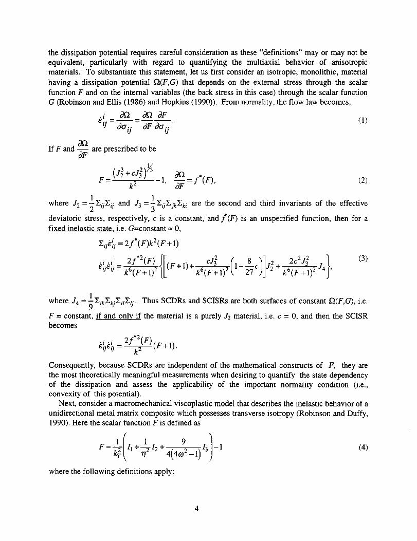
thedissipationpotentialrequirescarefulconsiderationasthese"definitions" mayor maynot beequivalent, particularly with regard to quantifying the multiaxial behavior of anisotropicmaterials. To substantiatethis statement,let usfirst consideran isotropic,monolithic,materialhaving a dissipationpotential f_(F,G) that dependson the externalstressthrough the scalarfunctionF and on the internal variables (the back stress in this case) through the scalar function
G (Robinson and Ellis (1986) and Hopkins (1990)). From normality, the flow law becomes,
klj_ o_ o_o3F00./j - OF 00" 6 (1)
If F and -ff_ are prescribed to be
v_(J +cg) o_ -*" F"k2 1, _=3' (), (2)
1 1where Je = "_ZaEij and J3 = EijZj_E_i are the second and third invariants of the effective
deviatoric stress, respectively, c is a constant, and f(F) is an unspecified function, then for a
fixed inelastic state, i.e. G=constant ---0,
.i =2f*(F)kZ(F+l)ZOe O
8/jg o-k6(F+l) 2 k6(F+l) 2 1__7 c J2+k6(F+l) 2"]4 ,
1
where -/4 = 2_EikZkjEilZlj" Thus SCDRs and SCISRs are both surfaces of constant f2(F,G), i.e.
F = constant, if and only if the material is a purely ,/2 material, i.e. c = 0, and then the SCISRbecomes
• i .i 2f'Z(F)(F+I )EQEij -- -._
Consequently, because SCDRs are independent of the mathematical constructs of F, they are
the most theoretically meaningful measurements when desiring to quantify the state dependency
of the dissipation and assess the applicability of the important normality condition (i.e.,
convexity of this potential).
Next, consider a macromechanical viscoplastic model that describes the inelastic behavior of a
unidirectional metal matrix composite which possesses transverse isotropy (Robinson and Duffy,
1990). Here the scalar function F is defined as
F=#III++I24 4(4(.o9_1)131-1 (4)
where the following definitions apply:
4
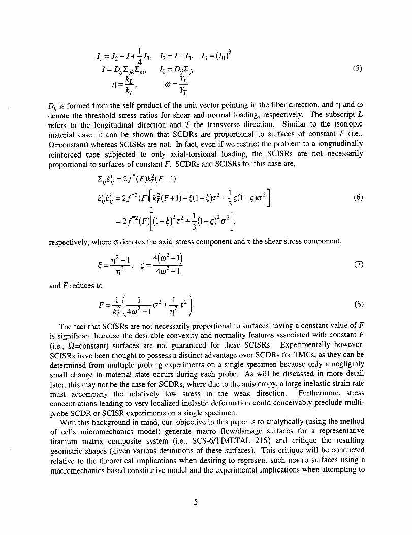
11 = J2 - I + 113 , 12 = 1 - 13,4
I = DijY_jk_,ki, I 0 = Dij_.ji
rT= k_, 0)= YLkT YT
13 =(I0) 3
(5)
Dij is formed from the self-product of the unit vector pointing in the fiber direction, and 1"1and co
denote the threshold stress ratios for shear and normal loading, respectively. The subscript L
refers to the longitudinal direction and T the transverse direction. Similar to the isotropic
material case, it can be shown that SCDRs are proportional to surfaces of constant F (i.e.,
f_=constant) whereas SCISRs are not. In fact, even if we restrict the problem to a longitudinally
not necessarilyreinforced tube subjected to only axial-torsional loading, the SCISRs are
proportional to surfaces of constant F. SCDRs and SCISRs for this case are,
Xij_ij = 2 f*(F)k_(F + l)
• i .i =2f*a(F)[@(F+l)__(l__),r2 1 ]--_(1- g)o "e (6)EijEij
= 2f*2(F)[(1-_)27r 2 +1(1- _)20-2],
respectively, where 0 denotes the axial stress component and z the shear stress component,
772 _ 4(0)2-1)
' g - 40) 2 - 1= _'/2 1 (7)
and F reduces to
1 1 o.2 + +,r2).F _ _-,.2T2(40)2 _ 1(8)
The fact that SCISRs are not necessarily proportional to surfaces having a constant value of F
is significant because the desirable convexity and normality features associated with constant F
(i.e., _=constant) surfaces are not guaranteed for these SCISRs. Experimentally however,
SCISRs have been thought to possess a distinct advantage over SCDRs for TMCs, as they can be
determined from multiple probing experiments on a single specimen because only a negligibly
small change in material state occurs during each probe. As will be discussed in more detail
later, this may not be the case for SCDRs, where due to the anisotropy, a large inelastic strain rate
must accompany the relatively low stress in the weak direction. Furthermore, stress
concentrations leading to very localized inelastic deformation could conceivably preclude multi-
probe SCDR or SCISR experiments on a single specimen.
With this background in mind, our objective in this paper is to analytically (using the method
of cells micromechanics model) generate macro flow/damage surfaces for a representative
titanium matrix composite system (i.e., SCS-6/TIMETAL 21S) and critique the resulting
geometric shapes (given various definitions of these surfaces). This critique will be conducted
relative to the theoretical implications when desiring to represent such macro surfaces using a
macromechanics based constitutive model and the experimental implications when attempting to
5

experimentallymeasurethem. It is hopedandanticipatedthatthis work will provideinsightandguidancefor futureexperimentalprogramsaimedat developing macroanisotropicconstitutivemodelsaswell asmultiaxially validatingcurrentlyproposed micromechanicaltheories.
MICROMECHANICAL MODEL
The method of cells micromechanical model (detailed in the monograph by Aboudi, 1991)
was used by Pindera and Aboudi (1988) to predict yield surfaces for MMCs. Micromechanics
was also employed by Dvorak (1991) to determine yield surfaces for MMCs using a bimodal
plasticity theory (Dvorak, 1987). In both of these efforts perfect bonding was assumed between
the fiber and matrix. Aboudi (1989) incorporated debonding due to shear loading into the
method of cells and predicted initial yield surfaces and debonding envelopes. The current work
employs a more general debonding model and employs different concepts to define flow/damagesurfaces.
The constitutive relations and/or parameters used to describe the fiber, matrix, fiber-matrix
interface, and the overall composite are presented here. A model TMC system (SCS-
6/TIMETAL 21S), having a unidirectional continuous silicon carbide (SIC) fiber reinforcement,
is used throughout this paper. Additionally, given that a model material concept (Arnold and
Castelli (1995)) holds, the same approach and conclusions found here should apply to other
TMCs systems as well.
Silicon Carbide Fibers
Textron's high-strength, high-stiffness, continuous SiC fibers (i.e., SCS-6) are approximated
as being isotropic and linear elastic. Furthermore, since the variation of elastic properties with
temperature is relatively small, the following isothermal elastic properties are used throughout:
Young's modulus, E = 400 GPa; Poisson ratio, v = 0.25; and coefficient of thermal expansion,CTE = 4.5×10 .6 °C "l.
Titanium Matrix
The titanium alloy TIMETAL 21S® (Ti-21s) is a metastable beta strip alloy, containing
approximately 21% alloying additions, that has high strength as well as good creep and oxidation
resistance. Ti-2 l s is commonly used in advanced metal matrix composites, hence its (isotropic)
viscoplastic response has been characterized for the model of Bodner and coworkers (Chan et al.,
1988), Chan and Linholm, 1990)) by Kroupa and Neu (1993) as well as a generalized
viscoplasticity with potential structure (GVIPS) model (Arnold and Saleeb, 1994) by Arnold et
al. (1996a,b). The GVIPS model of Arnold et al. (1996a, b) has been selected for the current
study. The model has one tensorial internal variable, the back stress, whose evolution includes
nonlinear kinematic hardening and both thermal and strain induced recovery mechanisms. The
use of a nonlinear compliance operator in the evolution law permits the flow and evolution laws
to be fully associated, which greatly influences the muitiaxial response under nonproportional
loading (Arnold et al., (1995)).
The flow and evolution equations are, respectively,
6
aomnEmnklbkl
bo
_lij =- tijkl( Akl - OklT ),
0 if k'<0
3k_Eij if P>0
if aij£ 0 < 0
if aijEij > 0(9)
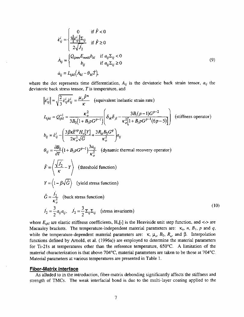
where the dot represents time differentiation, Aij is the deviatoric back strain tensor, a O the
deviatoric back stress tensor, T is temperature, and
_--k!.k{. = !a°_'n (equivalent inelastic strain rate)
-1 lf2o (¢_ikf_j I 3BI(p-1) Gp-2 )_jkl=Qi_kt= 3£(1--_pGP_l)_ l¢2o[l+BlPGp_l(6p_5) ] (stiffness operator)
( 3fllf_vpnv[Y]3RanOaq )2_;2_ 2bij = kiij - h aij
If o
Oij=-_--_(I+BlPGP-I)_ (dynamic thermal recovery operator)
(threshold function)
(yield stress function)
1'2 (back stress function)=._--yK"o
(lO)[2=3 3
_aoaij, J'2 =-_Z/jZij (stress invariants)
where E0el are elastic stiffness coefficients, Hv[.] is the Heaviside unit step function, and <.> are
Macauley brackets. The temperature-independent material parameters are: _, n, B_, p and q,
while the temperature-dependent material parameters are: _:, _to, Bo, R=, and 13- Interpolation
functions defined by Arnold, et al. (1996a)) are employed to determine the material parameters
for Ti-21s at temperatures other than the reference temperature, 650°C. A limitation of the
material characterization is that above 704°C, material parameters are taken to be those at 704°C.
Material parameters at various temperatures are presented in Table 1.
Fiber-Matrix Interface
As alluded to in the introduction, fiber-matrix debonding significantly affects the stiffness and
strength of TMCs. The weak interfacial bond is due to the multi-layer coating applied to the
7

fiber prior to consolidation. In this section,interfacialconstitutiveequationsbetweentractions,7",.,and displacements, ui, for an interface subjected to combined normal and tangential loading
are summarized from Lissenden (1996). Experimental results suggest that interfacial debonding
initiates upon the traction attaining a critical value - defined as the interfacial strength, To. For
the simple case of normal separation, the interfacial strength and ductility are sufficient to
characterize interracial separation. The ductility, uo, represents the interfacial displacement at
which the traction vanishes. If, after initiation, debonding proceeds in a smooth fashion, the
traction-displacement relation can be taken to be a cubic polynomial (Fig. 1):
__ + (u/3To k Uo) t.Uo )
To generalize eq. (11) for combined normal and tangential loading, an x,n,t interface
coordinate system is defined having the x-direction parallel to the fiber, n-direction normal to theTheinterface, and t-direction tangent to the interface and orthogonal to the fiber direction.
traction and displacement components are normalized as follows:
0 0 (12)
where o_ defines the tangential-to-normal ductility ratio and L defines the shear-to-normal
strength ratio. In addition, a normalized Coulomb frictional traction is defined
Tf = -/.t(-Tn) (13)
where g is the coefficient of static friction. A quadratic interaction of the tractions is employed
to predict the initiation of debonding to occur when
T-={(Tx - - 2 (__sgn(_)_f}2}l/2>l (14)_ sgn(rx)rl} +
where
forx 0sgn(x) = (15)for x>0
and Macauley brackets are used in the normal traction term because compressive loading is not
considered to be detrimental to the condition of the interface. Macauley brackets are used in the
tangential traction terms to ensure that tangential interfacial displacements do not occur until
after the static frictional force has been overcome.
Once debonding has initiated, the tractions can be related to the displacements by generalizing
eq. (1 I) and including frictional effects as follows:
-- * " " 1T,, = F (Umax)U,,, for tensile separanon/
Tx = F*(_max)_ x + sgn(ux)T f lfor0<_< 1 (16)
Tt= F*(umax)Ut + sgn(ut)Tf /

and
where
Tn = O, for tensile separation]
r x = sgn(ux)T f [forT>
/
_ = sgn(u,)_
1 (17)
_ = {_x2 +_2 +_2} 1/2 (18)
represents the normalized resultant interfacial displacement and
F* (fi')=(1- 3_ 2 + 2fi-3)/_ (19)
represents the generalized form of eq. (11). The maximum value of u = Umax is utilized in eq.
(19) to prevent the interface from being self-repairing upon unloading. The primary difference
between this model and that of Needleman (1987) and Tvergaard (1990) is the inclusion of a
debond initiation criterion.
Homoqenization
The method of cells (Aboudi, 1991) is a versatile micromechanical model for predicting the
overall response of composites. Overall elastic properties are determined in closed-form. The
microstructure is assumed to be doubly periodic, therefore it is sufficient to consider a unit cell
containing a single fiber. The unit cell consists of one fiber subcell and three matrix subcells,
although a recent generalization of the method permits an arbitrary number of subcells, enabling
the analysis of various microstructures (Paley and Aboudi, 1992 and Aboudi, 1995). For the
current work the standard version of the method of cells is adequate, the generalized method will
be used in future work to study the effects of microstructure on flow/damage surfaces. Subcells
are represented by rectangular geometries strictly as a mathematical convenience. The square
unit cell results in a material having cubic symmetry, no attempt has been made in the current
work to force the material to be transversely isotropic. Since equilibrium of tractions and
compatibility of displacements are imposed at the interfaces in an average sense, the actual
geometry of each subcell is only felt in a weighted average sense, i.e., the "square" fiber is really
only a pseudo-square fiber as only the ratio of//h is important.
A linear displacement field in each subcell is sufficient for determining overall response. The
displacement field is continuous except at the fiber-matrix interface, where average interfacial
displacement components are defined. Additionally, tractions must be continuous across subcell
interfaces. It is recognized that the subcell inelastic strains are approximate, but also that the
numerical efficiency of the model far exceeds that of other, perhaps more exact methods such as
finite element analysis using a large number of elements.
Altogether, homogenization provides 24 equations, but there are 30 unknown variables. The
fiber-matrix debonding relations presented in the previous section provide the additional six
equations. McGee and Herakovich (1992) showed how to reduce the full system of equations to
six with the interfacial displacements as the only unknown variables by considering different
types of applied loading.

RESULTS
Aboudi's micromechanical model was applied to an SiC/Ti composite having a fiber volume
fraction of 0.35 and the constituent properties discussed in the previous section. Residual
stresses associated with processing were accounted for by cooling the composite down from a
stress-free temperature of 815°C to room temperature in two hours. Subsequently, strain
controlled probing tests were conducted at a relatively slow rate, 101x/sec, to simulate the rate that
might be used in an experiment. The material was in a pristine state (as processed) at the
beginning of each probe and 180 probes were employed to determine each flow/damage surface.
The interface properties are shown in Table 2 and were chosen to be representative of an SiC/Ti
interface (Lissenden, 1996). However, in some cases the interfacial strength, To, has been
allowed to take on different values, e.g., 100 MPa and 300 MPa.
To illustrate the marked difference in the effects of matrix inelasticity and fiber-matrix
debonding, Fig. 2 shows the transverse tensile response (90 °) for; (i) matrix inelasticity/perfect
bonding (a continuous displacement field), (ii) an elastic matrix/debonding fiber-matrix interface,
and (iii) matrix inelasticity/debonding. Residual stresses associated with processing have been
considered in all three predictions. Clearly, debonding causes a deviation from proportionality
(DFP) prior to the onset of matrix inelasticity. Note that the unloading modulus (stiffness) has
been degraded for the two cases in which debonding occurred. The precise representation of this
unloading response, however, is relatively unimportant in the present work as only the loading
portion of each probing experiment is utilized.
The stress-strain responses for axial, transverse, and axial shear loadings are shown in Fig. 3
for three temperatures of interest: 23, 300, and 500°C. Residual stresses have been considered
and the (weak) interface properties shown in Table 2 were employed and assumed to be
temperature-independent. While the tensile axial response is independent of fiber-matrix
debonding, both the tensile transverse and shear responses are greatly affected by debonding as
one would expect. In this interface model, as in others, an instability associated with the
redistribution of stress from the fiber to the matrix as the interface debonds can occur, as it does
for transverse tension at 300 and 500°C. No significant instability is evident at 23°C, where the
interface properties were chosen to match experimental results. This suggests that more accurate
results could be obtained by determining the interface properties as a function of temperature,.
Flow Surfaces for Perfect Bondinq
Composite, or macro, flow surfaces of constant deviation from proportionality (SCDFPs) in
transverse-axial (c22-o'1 l), transverse-transverse ((_22-1_33), and shear-axial (GI2-all) stress spaces
are shown in Fig. 4 for the perfect bond condition and target deviations of 10_t and 0.2% (2000
ILt). The deviation from proportionality is due entirely to matrix inelasticity for perfect fiber-
matrix bonding. Thus, for this case, SCDFPs are akin to yield surfaces, but in general could also
be associated with internal damage. Overall SCDFPs are defined by the equivalent inelastic
invariant, lie i = _]3elje_, attaining a critical value; i.e., 10l.t and 0.2% as in Fig. 4. Thestrain
101.t definition gives an indication of first yielding and has been shown to be significant for
experimental yield surface determination (e.g., Phillips et al. (1972), Liu and Greenstreet (1976),
Helling et al. (1986), Lissenden et al. (1996b)) in monolithics. Likewise, the value of 0.2% is the
commonly used strain offset definition for monolithic materials and provides an indication of
10

significantplastic deformation. In reality, the 0.2% definition is frequentlynot applicabletoreinforcedmaterialsbecausethe reinforcing can fail prior to achievingan overall permanentstrain of 0.2%, particularly for loading in the direction of the reinforcing. This however,underscorestheimportanceof selectinganappropriateflow definition. Thetensilefiber fractureenvelope(for a fiber strengthof 4000MPa) is alsoshownin Fig. 4 to illustratethat0.2% is notrealistic for SiC/Ti-21s,nonethelessit is of academicvaluefor comparinglocalized inelasticitywith grossoverallinelasticity.
Applying thetargetvaluesof 10p.and0.2%to ourmodelTMC system,onecanseenotonly adifferencein sizeof the resultingflow (yield) surfacesdepictedin Fig. 4, but in the c22-_11and_22-c33stressspacesa noticeablechangein shapeis alsoevident. Table3 presentsa comparisonbetween the local (subcell) equivalent inelastic strains and their macroscopic (overall)counterpartsat variouslocationson the SCDFPsof Fig. 4. For theselectedpoints, the ratio ofthe maximum local equivalentinelasticstrain to the value of the macroscopicSCDFPrangesfrom 4.1 (pointE) to 6.1 (point A) and2.4(pointD) to 3.6 (pointH) for 101.tand0.2%SCDFPs,respectively.Thefact that themaximum-local-to-macroscopicequivalentinelasticstrainratio islargerfor the 10_ttargetvaluethanfor the0.2%caseprovidesthe properindicationthat matrixinelasticityis more localizedfor the 10_tSCDFP. The comersappearingon the 101.tSCDFPs(Fig. 4) areassociatedwith the changein locationof the localizedinelastic strain, i.e., on onesideof a comermatrix inelasticityoccursin onesubcellwhile on theothersideof thecomer itoccursin a different subcell. Thesecomersarean artifact of the approximatemicrostructureemployedby themethodof cellsandwerealsoobservedby PinderaandAboudi (1988). Futurework will investigatemore accuratemicrostructuralrepresentations.Finite element analysis(Dvoraket al., 1973)hasvalidatedtheoverallSCDFPsobtainedby themethodof cells.
The implicationsof theseresultsfor anexperimentalprogramresidein the fact that if it isdesiredto limit local (constituent)equivalentnonlinearstrains(soasto minimize anychangeininternal state)to 501a,for example,it would benecessaryto choosean overall DFP valuelessthan101ain the_22-_11stressspacewhile anoverallDFP valueslightlygreaterthan10p.couldbeemployed in the G_2-_11stress space. In either case, the in-situ, unmeasurable(usingextensometryor straingages)local, nonlinearstrainswould be approximately5 times greaterthantheirmacroscopic(measurable)counterparts.
Utilizing thealternativeSCDRconceptto defineoverall flow surfaces,thepredictedSCDRsfrom the currentmicro-modeland surfacesof F=constant (eq. (4)) from the macro-model of
Robinson and Duffy (1990) are shown in Fig. 5 for the case of no residual stresses. The strengths
of anisotropy required for the macro-model were obtained by using the micro-model to simulate
normal and shear loading experiments, yielding 09 = 1.7, 7?= 0.83, and kT = 610 MPa. The value
of F was chosen such that the micro-predicted and macro-predicted overall surfaces agreed in the
_2-_ stress space. The two overall SCDRs agree reasonably well in the Gz2-_ stress space,
but less so in the (_22-(_33 stress space where transverse stresses dominate. This observation is
supported by Arnold et al. (1993) in related work dealing with creep-plasticity interaction
wherein it was shown that non-associated models (such as Robinson and Duffy, 1990) can
accurately represent longitudinal behavior and yet are inadequate for transverse stresses, while
associated models of the GVIPS class (see Arnold and Saleeb, 1994, and Arnold et al., 1996a,b)
provide more consistent results. It is not obvious why applying a small amount of _e2 causes the
11

dissipationratetargetvalueto beachievedat a larger_11(Fig. 5), but this is indeedthe caseaswasalsoobservedby PinderaandAboudi (1988)andDvoraket al. (1973)for yield surfaces.
Thecentersof all surfacesin Fig. 5 arelocatedattheorigin becauseresidualstresseshavenotyetbeenincluded. If wenow accountfor residualstressesin the micro-modelthe centersof thesurfacesshift asshownin Fig. 6. The residualstressesareobservedto strengthenthecompositeunderequi-biaxial transversetension,but weakenit underequi-biaxial transversecompression(Fig. 6c). In themacro-modelwe attemptto accountfor residualstressesby equatingtheinitialback stressto the centerof the predictedmicro-modelsurface,here a11 = -241 MPa. The
comparison shown in Fig. 6 indicates that this is a viable macro-modelling technique to account
for a material having different flow stresses in tension and compression.
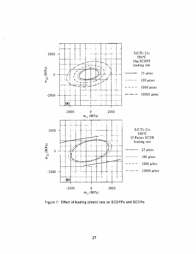
Applied loading (strain) rate can greatly affect flow behavior, particularly at elevated
temperatures. The SCDFPs shown in Fig. 7 for loading rates of 2, 20, 200, and 800 _/sec at
500°C illustrate the rate dependency that one would expect for such a surface (here one should
not think of a yield surface, but rather a surface of constant inelastic strain). Since inelastic
deformation takes time to occur, more inelasticity will result from slower loading rates. On the
other hand, SCDRs (and SCISRS) depend on the inelastic strain rate and thus are affected quite
differently by loading rate. SCDRs are observed to decrease in size, and change shape, as the
loading rate is increased. Furthermore, the loading rate is an upper bound on the inelastic strain
rate and if the loading rate is too slow (e.g., 25 l,t/sec in Fig. 7b) it may not be possible to
determine an entire SCDR. As will be discussed subsequently, a discontinuity in the inelastic
strain rate occurs at the threshold stress due to the formulation of the viscoplastic material model.
Once the loading rate gets fast enough, this discontinuity will cause the target dissipation rate
value to be exceeded at the threshold stress, which explains why SCDRs for 1000 _sec and
10000 l.t/sec are essentially the same and suggests that for extremely fast loading rates SCDRs
are rate-independent.
Flow/Damage Surfaces
Damage envelopes for metal matrix composites have previously been predicted by Aboudi
(1989). Here, the concept of a damage envelope has been combined with that of a yield or flow
surface resulting in SCDFPs (rate-independent) or SCDRs and SCISRs (rate-dependent). In the
current work we are defining damage to be fiber-matrix debonding, other forms of damage such
as matrix cracking, fiber breakage, and void growth are specifically excluded. The effects of
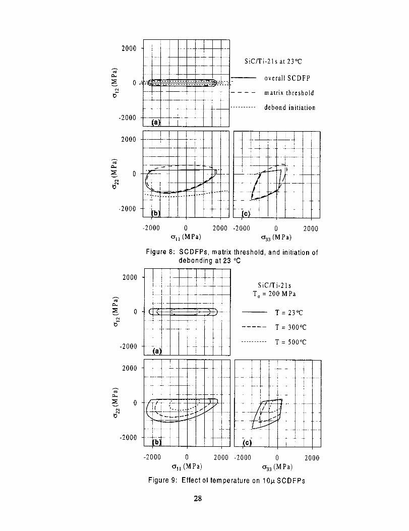
local events (i.e., debond initiation and subcell stresses attaining their threshold value, J_ _ 0) on
overall SCDFPs are shown in Fig. 8 by superimposing damage initiation (eq. (14)) envelopes and
matrix threshold (eq. (10)) loci on overall 10_t SCDFPs in transverse-axial (_22-_11), transverse-
transverse (1_22-(_33), and shear-axial (_2-_11) stress spaces at 23°C. Be aware that the initiation
of debonding gives no indication of how the interfacial displacements accrue. It is clear from
Fig. 8, however, that axial loading and compressive biaxial transverse loading do not initiate
debonding. (As will be shown later, axial compression can lead to debonding associated with
Poisson expansion.) The lower extreme of the debonding envelope in the _22-_11 stress space
(Fig. 8b) is associated with overall (macro) Poisson expansion due to compressive transverse
applied stresses. Here, for an interfacial strength of 200 MPa, the DFP target value is attained
prior to the matrix threshold when debonding occurs due to transverse loading but not due to
shear loading, thereby once again suggesting that debonding affects the transverse tensile
12

responsemore than it does the shearresponse,as one might expect. Thus, the overall
flow/damage SCDFP is essentially bimodal for normal loadings, in that it is the intersection of
the debonding envelope and matrix threshold. However, in the presence of shear loading, an
interaction between debonding and matrix inelasticity lead to deviation from proportionality.
The effect of temperature on 10_t SCDFPs is illustrated in Fig. 9 where flow/damage surfaces
have been predicted for 23,300, and 500°C. As expected, in all three stress spaces the size of the
SCDFP decreases with increasing isothermal conditions and, as the interface properties were
taken to be temperature-independent, the only effect temperature has on the initiation of
debonding is in the magnitude of residual stresses produced (as these stresses ,which serve to
clamp the interface together, relax as the temperature increases). As depicted in Fig. 3, the
predicted deviation from proportionality associated with debonding occurs within a relatively
small range of transverse and shear stresses.
Similarly, Fig. 10 shows how interfacial strength affects SCDFPs at 23°C. In addition to
SCDFPs for interracial strengths of 100, 200, and 300 MPa, the perfect bond condition is also
shown. In _22-oll stress space (Fig. 10b), debonding due to Poisson expansion affects the
SCDFP for compressive axial and transverse stresses in the case of an interfacial strength of 100
MPa, but not for higher interfacial strengths. As the interfacial strength of the composite is
increased, the size of the SCDFP increases in the region where debonding has an influence with
the perfect bond condition as the extreme (Fig. 10).
The effect of interface ductility, Uo, was also studied, but found to have a relatively small
effect on the size and shape of the flow/damage surfaces. This was expected, since interface
ductility only affects the rate at which stresses are redistributed from the fiber to the matrix upon
debonding. In the (_22-(_11 and (_33-(_22 stress spaces, inelasticity is observed almost immediately
after debond initiation and only an unrealistically high ductility would impact the inelastic
surfaces. Greater interface ductility did result in slightly larger inelastic surfaces in the G12-cil
stress space (not shown).
Now consider the construction of rate-dependent SCDRs and SCISRs at 500°C (Fig. 11 and
13). Both types of surfaces depend on the overall inelastic (including debonding effects) strain
rate. Here it was found that the applied strain rate of 10_/sec was too slow, in that it placed an
upper bound on the inelastic strain rate and severely limited the range of values that could be
used for complete SCDR and SCISR determinations. Thus, the applied probing strain rate was
increased to 100_/sec for all subsequent results. With respect to SCDRs, three target values, i.e.,
1, 20, and 35 Pa/sec, are shown in three stress spaces at 500°C in Fig. 11. As with SCDFPs,
SCDRs exhibit straight segments where fiber-matrix debonding dominates and fairly sharp
comers at the intersection of regions dominated by matrix inelasticity and those dominated by
debonding.
It is important to note that these fairly geometrically complex macro SCDRs, were predicted
from a micro-model having relatively simple constituent constitutive relations (i.e., a J2
viscoplasticity theory for the matrix and a simple multiaxial interface model). Conversely, the
required mathematical form of a macro-model would have to be quite sophisticated to obtain the
predicted SCDR representations shown in Fig. 11. The primary difficulty in modelling TMCs at
the macroscale would appear to be in properly accounting for strain and stress localizations and
the differences in tension and compression associated with damage.
13

Even if viablemathematicalconstructsfor thedissipationpotentialcanbeshownto acuratelypredictdeformation,thereis still a questionwhethera macro-modelcanbeusedfor failure andlife predictionbecausetheseareknownto dependon localevents.However,with amicro-modelwe canexaminelocal behavior. Consequently,we showthe local equivalentinelastic strainscorrespondingto locationsmarkedA-M on Fig. 1lb andN-S on Fig. 1la tabulatedin Table4.The local equivalent inelastic strainsare observedto vary greatly with loading and location.Transversecompression(points J, K, and L, Fig. lib) createsthe largestlocalized inelasticstrainsshownin Table4; 47_t, 12801x,and24901.tfor 1, 20, and 35 Pa/sec,respectively. Thelargestlocal-to-macroinelastic strain ratio is 4.7 and occurs for the 1 Pa/secSCDR undertransversecompression.The minimum subcell inelasticstrainfor eachsurfacewaszero. Fortransversetension(pointsD, E, andF in Fig. 1lb andTable4) themacroinelasticstrainis quitelargedueto debonding,while the local inelasticstrainsareeitherzeroor relativelysmall.
It is known that the overall inelastic strain rate, and hencethe dissipation rate, has adiscontinuityassociatedwith the initiation of debonding(aswell aswhen the matrix thresholdstressis attained),this discontinuityis shownin Fig. 12 for pointsE and M on the 20 Pa/secSCDR.Also shownin Fig. 12is the increasein theoverall(macro)J2 with the applied strain e22,
clearly the values of ./2 are much larger at point M than at point E due to the presence of an axial
stress. The concavity in the 20 Pa/sec SCDR at point E in Fig. 1 lb is associated with the
redistribution of fiber stresses to the matrix upon debonding, as such it is an artifact of the type of
interface model employed and consequently should not be alarming.
Inelastic surfaces can be determined experimentally at elevated temperature by applying axial-
torsional loading to a thin-walled tubular specimen. It is desirable to determine an entire
inelastic surface using a single specimen to avoid specimen-to-specimen scatter in results and
make the program economically feasible. This requires absolutely minimizing the amount of
inelastic deformation that occurs in each probe of the surface as any theory would require that
these tests be performed at a fixed inelastic state of the material. Tests have been successfully
conducted for target values of up to 1001,t of permanent strain in each probe direction for
monolithic materials containing no internal damage (e.g., Battiste and Ball, 1988).
Consequently, in composite testing we must be aware of both the expected macro and micro
inelastic strain fields developed during a given probe. As a result, we have tabulated in Table 4
the predicted local equivalent inelastic strains that accompany the SCDRs in the _12-t_ stress
space for points N-S denoted in Fig. 1 la. For the applied strain rate of 100g/sec it appears
feasible to experimentally determine a 1 Pa/sec SCDR on a single specimen as both the local and
macro equivalent inelastic strains should be relatively small at points N and Q. However, it may
not be possible to experimentally determine a complete 1 Pa/sec SCDR on a single specimen
because of a change in material state associated with overshooting the target value that would be
likely to occur due to the relatively large (predicted) discontinuity in the dissipation rate (e.g., 10-
15 Pa/sec shown in Fig. 12) associated with the initiation of debonding. Further, there is a wide
disparity in macroscopic equivalent inelastic strain for shear and axial compressive loading given
a value of dissipation rate. The ratio of macro equivalent inelastic strain between shear and axial
compression for SCDRs of 1, 20, and 35 Pa/sec is 4.5 (N/Q), 9.5 (O/R), and 18.6 (P/S),
respectively (Table 4). This wide range of equivalent inelastic strains could preclude the use of a
single specimen to experimentally determine SCDRs, especially for relatively large dissipation
rate target values. It should also be reaffirmed that the inelastic strain rate, and thus SCDRs and
SCISRs, is very sensitive to the loading rate due to matrix viscoplasticity.
14

The shapesof theSCDRsin thethreestressspaces(Fig. 11)indicatethataxial-torsionaltestson longitudinally reinforcedthin-walledtubularspecimensarenot the mostdiscriminatingtestsfor validatingthe mathematicalconstructionof the dissipationpotential.Axial-transverseloadprobingexperimentsconductedon an in-planebiaxial testmachine,(while beingmoredifficultto conductdueto stressandstraingradientsin theplaneof theplate,couplingbetweenaxialandtransversestrains,and the large potential for buckling in compression),would provide morediscriminatingandvaluableinformationfor theconstructionandvalidationof themathematicalrepresentationof the dissipationpotential. Biaxial transverseloading, _22-o33,would alsoprovidevaluableinformation,althoughspecimenswouldbecostlyanddifficult to manufacture.Alternatively, circumferentially-reinforcedthin walled tubes could be employed to obtainsurfacesin the012-022stressspace,andeventhoughthis stressspacewasnot consideredin thepresentwork thesesurfacesare likely to have complex geometriesbecauseboth shearandtransverseloadingresultin debonding.
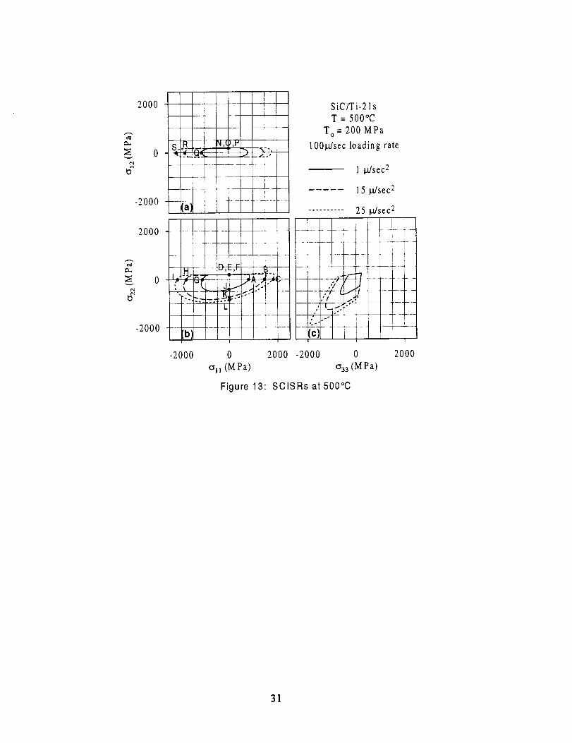
Figure 13 shows 1, 15 and 25 _/sec 2 SCISRs at 500°C, again the target values were chosen to
provide the largest possible range of SCISRs. SCDRs and SCISRs are quite similar for small
values, 1 Pa/sec and 1 _/sec 2, respectively, as can be seen by comparing Fig. 11 and 13. The
reason for the similarity appears to be that these small values really correspond to the initiation of• i .i
either debonding or matrix inelasticity, causing the difference between Zijklj and eijeij to be
small. For larger target values, the shapes of SCDRs (Fig. 1 1) and SCISRs (Fig. 13) become
quite different in all three stress spaces, particularly the cr22-c_33stress space. It should be pointed• i -i .i
out that since Zijeij and eOeij are different quantities, one should not expect a one-to-one
correspondence between SCDRs and SCISRs. However, the values for SCDRs and SCISRs
plotted in Fig. 1 1 and 13 were chosen to provide the widest possible range for the given loading
rate and temperature, facilitating comparisons of trends between SCDRs and SCISRs for small,
medium and large amounts of inelasticity. It is apparent that SCISRs are more affected by
debonding than are SCDRs. This could be related to the discontinuity in the inelastic strain rate
associated with the initiation of debonding. For a SCDR the discontinuous _ij is multiplied by
the effective stress Z 0, while for a SCISR the discontinuity is magnified by multiplying _ij by
itself.
Local and macro equivalent inelastic strains associated with the SCISRs shown in Fig. 13 are
presented in Table 5. Typically, both the local and macro equivalent inelastic strains are lower for
SCISRs than for SCDRs. In some cases the macro equivalent inelastic strain is considerably
smaller for SCISRs than for SCDRs (transverse tension and shear). However, even for SCISRs
the local equivalent inelastic strains can be quite high in some cases (axial tension/compression),
having significant implications for experimental programs.
CONCLUSIONS
In this study we have generated macro flow/damage surfaces using three distinct definitions
for these surfaces, i.e., "yield" (deviation from proportionality), surfaces of constant inelastic
strain rate (SCISRs), and surfaces of constant dissipation rate (SCDRs). These surfaces have
been calculated using the method of cells micromechanics model for a representative silicon
carbide/titanium metal matrix composite (i.e., SCS-6/TIMETAL 21S) at temperatures ranging
15

from 23 to 500°C. The micromechanicalanalysisexplicitly accountsfor matrix viscoplasticity,fiber-matrixdebonding,andresidualstresses.Themainconclusionsof thisstudyarelistedhere.
• The various macro flow/damage surfaces possess differences in tension and compression
with their centers being offset from the origins as a result of the presence of internal
(microscale) residual stress fields.
• The shape of these surfaces are distinctly affected by the presence of internal damage (i.e.,
fiber-matrix debonding) as well as the applied biaxial stress state.
• The size of surfaces of constant deviation from proportionality (SCDFPs) and SCISRs is
decreased by debonding for transverse tension and shear loadings, distorting the shape of the
inelastic surface. SCDRs are also affected by debonding, but to a lesser extent.
• The range of possible values for SCDRs determined by various applied loadings is limited by
the disparity in stress magnitudes at the onset of inelasticity. This disparity in stress
magnitude is attributed to the presence of fiber induced anisotropy and fiber-matrix
debonding.
• Clearly axial/torsion tests are not the most discriminating tests for differentiating between
surface definitions or illustrating the required mathematical constructs of the dissipation
potential. Here, in-plane biaxial tests appear to be the more important and informative teststo conduct.
• The magnitude of the pertinent macro target value significantly influences the magnitude of
the resulting internal state (i.e., the magnitude of local inelastic strain and internal stress) and
consequently the reusability of a single test specimen for multiple surface probes.
• Given a macroscale starting viewpoint, relatively sophisticated mathematical representations
(in the form of the invariants employed, the inclusion of J3, and possibly 11, etc.) for the
macro dissipation potential would be required to capture the complex geometric properties of
the various flow/damage surfaces. In contrast, employing a micromechanics model, such as
the method of cells, one can use a relatively simple constituent constitutive (e.g., J2
viscoplastic theory for the matrix) relation to obtain the required macro multiaxial behavior.
• Fiber-matrix debonding is independent of axial loading, except possibly in the case of axial
compression, where debonding could occur due to transverse Poisson expansion.
• A key parameter in the ability to determine the entire SCDR accurately is the applied strainrate.
The results of this study are in agreement with those from previous macro- and
micromechanics studies relating to yield and flow surfaces for metal matrix composites
exhibiting perfect bonding. Here we have included fiber-matrix debonding and paid particular
attention to different target values as well as different definitions of overall flow/damage.
Additionally, the micromechanics model has permitted us to compare overall and local stress and
strain fields as well as provide guidance for an experimental program aimed at validating
multiaxial constitutive relations for metal matrix composites.
16

REFERENCES
Aboudi, J., 1989, "'Micromechanical analysis of fibrous composites with Coulomb frictional
slippage between the phases," Mechanics of Materials, Vol. 8, pp. 103-115.
Aboudi, J., 1991, Mechanics of Composite Materials a Unified Micromechanical Approach,
Elsevier, Amsterdam.
Aboudi, J., 1995, "Micromechanical analysis of thermo-inelastic multiphase short-fiber
composites", Composites Engineering, Vol. 5, No. 7, pp. 839-850.
Arnold, S.M. and Castelli, M.G., 1995, "What constitutes a model material?" H1TEMP
Review 1995, Volume II: Compressor/Turbine Materials, NASA CP-10178, pp. 35A: 1-18.
Arnold, S.M. and Saleeb, A.F., 1994, "On the thermodynamic framework of generalized
coupled thermoelastic-viscoplastic-damage modeling," International Journal of Plasticity, Vol.
10 No. 3, pp. 263-278, Also NASA TM-105349, 1991.
Arnold, S.M., Saleeb, A.F., and Wilt T.E., 1995, "A modeling investigation of thermal and
strain induced recovery and nonlinear hardening in potential based viscoplasticity," Journal of
Engineering Materials and Technology, Vol. 117, pp. 157-167. Also NASA TM-106122, 1993.
Amold, S.M., Wilt T.E., Saleeb, A.F., and Castelli, M.G., 1993, "An investigation of macro
and micromechanical approaches for a model MMC system," HITEMP Review 1993, Volume 11:
Compressor/Turbine Materials, NASA CP-19117, pp. 52:1-12.
Arnold, S.M., Saleeb, A.F., and Castelli, M.G., 1996a "A fully associative, nonisothermal,
nonlinear kinematic, unified viscoplastic model for titanium alloys," Thermo-Mechanical
Fatigue Behavior of Materials: Second Volume, ASTM STP-1263, M. Verrilli and M. G. Castelli,
Eds. Also NASA TM-106926, 1995.
Arnold, S.M., Saleeb, A.F., and Castelli, M.G., 1996b, "A fully associative, nonlinear
kinematic, unified viscoplastic model for titanium alloys," Life Prediction Methodology for
Titanium Matrix Composites, ASTM STP-1253, W.S. Johnson, J.M. Larsen, and B.N. Cox, Eds.
Also NASA TM-106609, 1995.
Battiste, R. L. and Ball, S. J., 1986, "Determination of surfaces of constant inelastic strain rate
at elevated temperatures," Turbine Engine Hot Section Technology, NASA CP-2444, NASA
Lewis Research Center, Cleveland, OH, pp. 307-325.
Bodner, S.R., 1987, "Review of a unified elastic-viscoplastic theory," Unified Constitutive
Equations for Creep and Plasticity, A.K. Miller, ed., Elsevier, Amsterdam, pp. 273-301.
Chan, K.S., Bodner, S.R., and Lindholm, U.S., 1988, "Phenomenological modeling of
hardening and thermal recovery in metals," Journal of Engineering Materials and Technology,
Vol. 110, pp. 1-8.
Chan, K.S. and Lindholm, U.S., 1990, "Inelastic deformation under nonisothermal loading,"
Journal of Engineering Materials and Technology, Vol. 112, pp. 15-25.
Clinard, J.A. and Lacombe, C., 1988, "Determination of multiaxial flow surfaces at elevated
temperatures using the concept of dissipation potential", Oak Ridge National Laboratory,ORNL TM-10787.
Dvorak, G.J., Rao, M.S.M, and Tam, J.Q., "Yielding in unidirectional composites under
extemal loads and temperature changes," Journal of Composite Materials, Vol. 7, pp. 194--216.
Dvorak, G.J., 1987, "Bimodal theory of fibrous composite materials," Acta Mechanica, Vol.
69, pp. 219-24.
17

Dvorak, G.J., 1991, "Plasticity theoriesfor fibrous compositematerials," Metal Matrix
Composites: Mechanisms and Properties, Everett, R.K. and Arsenault, R.J., eds. Academic
Press, Boston, pp. 1-77.
Ellis, J. R., Robinson, D.N., and Pugh, C.E., 1978, "Behavior of annealed type 316 stainless
steel under monotonic and cyclic loading at room temperature", Journal of Nuclear Engineering
and Design, Vol. 47, pp. 115-123.
Freed, A.D. and Walker, K.P., 1995, "Viscoplastic model development with an eye toward
characterization," Journal of Engineering Materials and Technology, Vol. 117, pp. 8-13.
Helling, D.E., Miller, A.K., and Stout, M.G., 1986, "An experimental investigation of the
yield loci of 1100-0 aluminum, 70:30 brass, and an overaged 2024 aluminum alloy after various
prestrains," Journal of Engineering Materials and Technology, Vol. 108, pp. 313-320.
Helling, D.E. and Miller, A.K., 1987, "The incorporation of yield surface distortion into a
unified constitutive model, Part 1 : equation development," Acta Mechanica, Vol. 69, pp. 9-23.
Hopkins S.E., 1990, "A unified multiaxial J2, J3 theory of viscoplasticity for high-temperature
isotropic materials", Masters Thesis, University of Akron, OH.
Jansson, S., Deve, H.E., and Evans, A.G., 1991, "The anisotropic mechanical properties of a
Ti matrix composite reinforced with SiC fibers," Metallurgical Transactions, Vol. 22A, pp.2975-2984.
Johnson, W.S., Lubowinski, S.J., and Highsmith, A.L., 1990, "Mechanical characterization of
unnotched SCS6/Ti-15-3 metal matrix composites at room temperature," Thermal and
Mechanical Behavior of Metal Matrix and Ceramic Matrix Composites, ASTM STP 1080,
Kennedy, J.M. et al., eds., American Society for Testing and Materials, Philadelphia, pp. 193-218.
Kroupa, J.L. and Neu, R.W., 1993, "Implementation of a nonisothermal unified inelastic-
strain theory in ADINA6.0 for a titanium alloy - user guide," Wright Laboratory WL-TR-93-4005.
Lerch, B.A., and Saltsman, J.F., 1993, "Tensile deformation damage in SiC/Ti-15-3
laminates," Composite Materials: Fatigue and Fracture, Fourth Volume, ASTM STP 1156,
Stinchcomb, W.W. and Ashbaugh, N.E., eds., American Society for Testing and Materials,
Philadelphia, pp. 161-175.
Lissenden, C.J., Lerch, B.A., and Herakovich, C.T., 1996a, "Response of SiC/Ti under
combined loading - part lll: microstructural evaluation," Journal of Composite Materials, Vol.
30, pp. 84-108.
Lissenden, C.J., Lerch, B.A., Ellis, J.R., and Robinson, D.N., 1996b, "Verification of
experimental techniques for flow surface determination," NASA TM- 107053.
Lissenden, C.J., 1996, "Fiber-matrix interracial constitutive relations for viscoplastic
composites," submitted.
Liu, K.C. and Greenstreet, W.L., 1976, "Experimental studies to examine elastic-plastic
behavior of metal alloys used in nuclear structures," Constitutive Equations in Viscoplasticity:
Computational and Engineering Aspects, AMD-Vol. 20, American Society of Mechanical
Engineers, New York, pp. 35-56.
Majumdar, B.S. and Newaz, G.M., 1992, "Inelastic deformation of metal matrix composites:
plasticity and damage mechanisms," Philosophical Magazine, Vol. A66, pp. 187-212.
McGee, J.D. and Herakovich, C.T., 1992, "Micromechanics of fiber/matrix debonding,"
University of Virginia Report AM-92-01.
18

Needleman,A., 1987,"A continuummodel for void nucleationby inclusion debonding,"Journal of Applied Mechanics, Vol. 54, pp. 525-531.
Oytana, C., Delobelle, P., and Mermet, A., 1982, "Constitutive equations study in biaxial
stress experiments", Journal of Engineering Materials and Technology, Vol. 104, pp. 1-11.
Paley, M. and Aboudi, J., 1992, "Micromechanical Analysis of Composites by theGeneralized Cells Model", Mechanics of Materials, Vol. 14, pp. 127-139.
Phillips, A., 1974, "The Foundations of Thermoplasticity-Experiment and Theory," Topics in
Applied Continuum Mechanics, J.L. Zemen and F. Ziegler (Eds.), Springer Verlag, Wien-New
York, pp. 1-21.
Phillips, A., Liu, C.S., Justusson, J.W., 1972, "An experimental investigation of yield surfaces
at elevated temperature," Acta Mechanica, Vol. 14, pp. 119-146.
Pindera, M.J. and Aboudi, J., 1988, "Micromechanical analysis of yielding of metal matrix
composites," International Journal of Plasticity, Vol. 4, pp. 195-214.Robinson, D.N., 1985, "On Thermomechanical Testing in Support of Constitutive Equation
Development for High-Temperature Alloys", NASA CR-174879, NASA Lewis Research Center,
Cleveland, OH.
Robinson, D.N. and Ellis J.R., 1986, "A multiaxial theory of viscoplasticity for isotropic
materials," Turbine Engine Hot Section Technology, NASA CP-2444, NASA Lewis Research
Center, Cleveland, OH, pp. 283-292.
Robinson, D.N. and Duffy, S.F., 1990, "Continuum deformation theory for high-temperature
metallic composites," ASCE Journal of Engineering Mechanics, Vol. 116, pp. 832-844.
Saleeb, A.F. and Wilt, T.E., 1993, "Analysis of the Anisotropic Viscoplastic-Damage
Response of Composite Laminates- Continuum Basis and Computational Algorithms",
International Journal of Numerical Methods in Engineering, Vol. 36, pp. 1629-1660.
Spencer, A.J.M. , 1972, Deformations of Fiber-Reinforced Materials, Clarendon Press,
Oxford.
Tvergaard, V., 1990, "Effect of fibre debonding in a whisker-reinforced metal," Materials
Science and Engineering, Vol. A125, pp. 203-213.
Walker, K.P., 1981, "Research and development program for nonlinear structural modeling
with advanced time-temperature dependent constitutive relationships," NASA CR-165533.
19

TABLE 1" Ti-21s MATERIAL PARAMETERS
23oc 300oc 500oc 650oc 704oc
E (GPa) 114.1 107.9 95.1 80.7 59.7
CTE (_t°C a) 7.717 9.209 10.70 12.13 14.09
_: (MPa) 1029 768.4 254.2 5.861 0.756
(MPa/sec) 667.6 137.8 1.45×10 .3 6.19×10 .9 1.13×10 11
Bo (MPa) 6.908x10 5 1.035x10 -4 2.756x10 "4 5.870x10 "4 6.346x10 _
R_ (1/sec) 0 0 1.68X10 -7 1.00X 10 -6 6.01x10 5
[3 0.001 0 0 0 0
temperature-independent: v = 0.365, n = 3.3, Bl = 0.05, p = 1.8, q = 1.35
TABLE 2: INTERFACE PROPERTIES
To (MPa) Uo (gm) rl a _t
200 9 1 8 0.4
2O

NO.2.).
(21): (22)|
i
TABLE 3: MATRIX EQUIVALENT INELASTIC STRAINSASSOCIATED WITH SCDFPs SHOWN IN FIGURE 4
Location subcell 12 subcell 21 subcell 22 maximum
(see Fig. 4) (xl0 -6) (xl0 -6) (xl0 -6) local/macro
DFP
21

TABLE 4: MATRIX EQUIVALENT INELASTIC STRAINS
ASSOCIATED WITH SCDRs SHOWN IN FIGURE 11
Location subcell 12 subcell21 subcel122 macro DFP maximum SCDR
(see Fig. 11) (×10 -6) (×10-6) (xlO -_) (×10 -_) local/macro (Pa/sec)
22
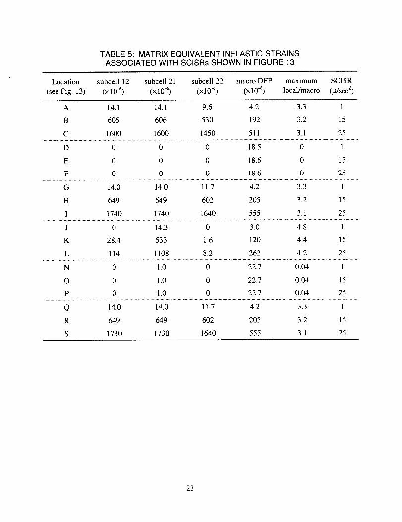
TABLE 5: MATRIX EQUIVALENT INELASTIC STRAINS
ASSOCIATED WITH SCISRs SHOWN IN FIGURE 13
Location subcell 12 subcell 21 subcell 22 macro DFP maximum SCISR
(see Fig. 13) (xl0 -6) (xl0 -6) (xl0 -6) (xl0 -_) local/macro (g/sec 2)
23

<_22
(MPa)
T
To
2000
t500
1000
5O0
0 1Uw
U o
Figure 1: Traction-separation relationfor purely normal separation
0
0.00
Figure 2:
SiC/Ti-21 s
.................ymatrix plasticity ........... ;';
- perfect bond..-- ..... /t /
,'j •
- .-' debonding, :,,'_/
/ elastic H
__ .//_bonding,
/'/, , _ , ",-'_l mtatri_ p la,sticily
0.01 0.02
_2
Comparison of matrix inelasticity andfiber-matrix debonding
24

4000
3000
2000
1000
0600
_E 400,,=...
0
e_,,, 200eq
/.f.
"/5"
f,,.fji
s"
axial
SiC/Ti-21s
T = 23°C
T = 300°C
........ T = 500°C
transverseg ! I I ! I I I I I
UO.O0 0.01 0.(
Ell and E22
I I I I I I 1 I I
m
axial shear
,2).00 0.01 0.02
_12
2000
0
-2000
2000
0
-2000
Figure 3: Stress-strain response at 23,300, and 500°C
h
ten,, il_ fiberfr 3 c Ill r_l--.-,
/ SiC/Ti-21s/!
l ._ ,-.q perfect bond
_ lOp. offset
_tz L......... 0.2% offset-" _'L,On
I-2000 0 2000 -2000 0 2000
all (M Pa) o33 (M Pa)
Figure 4: SCDFPs for perfect bonding at 23°C
25

2000
2= 0¢q
D
-2000
20OO
0
-2000
1
______+_______ _
-2000
II
1! .....
-- 4 - - -r
i
i
0 2000
oll (MPa)
SiC/Ti-2 ls
perfect bondno residual stresses
overall flow surfaces
micro-predicted, 1 Pa/sec SCDR
.... macro-predicted, F = constant
m.
-2000
_,f--1 ÷ _ •g
:c)t
0 2000
033 (M Pa)
D
¢N
Figure 5:
= i
2000 -_J !
4
o -I<
-2000
2000
0
-2000
Comparison of micro- and macro-predicted overallflow surfaces at 23°C, no residual stresses
u __m
I
[a_] __
Ib_
• I
J
/
xxIF_W" -II
,c._nNL__._.
I[ .....i
SiC/Ti-21s
perfect bondresidual stresses
overall flow surfaces
micro-predicted, I Pa/sec SCDR
.... macro-predicted, F = constant
iL * "l"
-- _ .... -"4 -- ---
t_ L,,_ _ p_
- L ":7"
I(c]i
-2000 0 2000 -2000
oll (MPa)
mI
tt
Itw
• ! _I+b
-tltt
i!
I I j
0 2000
033 (M Pa)
Figure 6" Comparison of micro- and macro-predicted overallflow surfaces at 23°C, residual stresses included
26
2000- ......
w, ,
-2000 -
(a)
. !"/--J- /.j - _
-- l .....
L
L--I
2000 -
-2000
-2000 0 2000
(Ill (M Pa)
SiC/Ti-21 s500°C
10_SCDFP
loading rate
25 _/sec
.......... 100 _sec
1000 _sec
10000 lu/sec
SiC/Ti-21s500°C
35 Pa/sec SCDR
loading rate
25 _sec
.......... 100 IMsec
1000 IMsec
10000 I.t/sec
Figure 7: Effect of loading (strain) rate on SCDFPs and SCDRs
27
¢X,
t"q
o,I
Ca..
t"q
¢.q¢q
2000
-2000
2000
-2000
2000
-2000
2000
-2000
-._..-_,._,.._ _ _._..- _----:/-<--_-_ =----,
_ ] _
-- - -- -- m
SiCITi-21 s at 23°C
overall SCDFP
matrix threshold
------ ......... debond initiation
..... 7___
-_b_-I-7 - ,:o>J!IiI-2000 0 2000 -2000
_ru (MPa)
----.'-& -_-I ......))
I
0 2000
_33(M Pa)
Figure 8: SCDFPs, matrix threshold, and initiation of
debonding at 23 °C
' I
;-3-4
1
.......... tit!ii:
[b) c
-2000 0 2000 -2000 0
olt (M Pa) 033 (M Pa)
Figure 9: Effect of temperature on IOI-tSCDFPs
SiC/Ti-21 s
T O= 200 M Pa
T = 23°(2
T = 300°C
.......... T = 500°(2
2000
28

¢-,]
2000
-2000
2000
-2000
(a) I
--:b: -t.... i-T
-N 7
- -(c).....
SiC/Ti-21 s
101.t SCDPPsT = 23°C
perfect bond
T O= 100 MPa
TO= 200 M Pa
T O= 300 MPa
-2000 0 2000 -2000 0 2000
olt (M Pa) 033 (M Pa)
Figure 10: Effect of interfacial strength on SCDFPs at 23°C
29

t_
t",.I
2000
-2000
2000
-2000
e_
c_
A
p I r
, __ ¢'_ I
:_12
,,, ,T ,
.._--= _l._,-G( ',_, d,_
-_--...r_ _
(hi
itJ I
/ /,f.
_II
-2000
SiC/Ti-21s
T = 500°C
T O= 200 M Pa
1001Msec loading rate
1 Pa/sec
20 Pa/sec
_L
.......... 35 Pa/sec
f
•" /
i
0 2000 -2000 0
oll (M Pa) (_33(M Pa)
Figure 11: SCDRs at 500°C
2000
20
i0
ooOO_/
diss. rate __\
J -t-r_M _,/ ^
.,__Ell = 0.898_2
0E+0 2E-3 4E-3
_2
Figure 12: Dissipation rate increase at points
E and M (located on Fig. 11)
3E+5
2E+5
1E+5
0E+0
30
2000
*g
0_q
*gca.
=E_q
-2000
2000
-2000
_ lq--- _ ,c?,v
..... L
...._ ....5-2000
SiC/Ti-21s
T = 500°C
T o = 200 MPa
100_sec loading rate
1 _/sec 2
15 IMsec2
.......... 25 _sec 2
• /
--- ,_TS.. _ ............jt .' T ......
,S ._ I.-
0 2000 -2000 0
oil (MPa) _33(MPa)
Figure 13" SClSRsat500°C
2000
31

I Form ApprovedREPORT DOCUMENTATION PAGE OMBNo.0704.-0188
Public reportingburdenfo¢ thi=collectionnf informatiorlis esti_ to avecage 1 hourpet response, Including the time lor iiw'..m_ng ImltnJctio_, .ima_hlng esisllng dala ioum_.,gatheringand n'_lnlairdngthe data needed, and completing .,andreviewingthe collect=onof I.nlormal_ _.eno comm_t= r.ngat_.ngthe..bu_en estfrrae __any other aspect o( th_collectionof information,includingsuggestmnsfor reducingth=$burden. 1o WashingtonHeaoquatters _ewloss. u_'ectorateTot imoffnatlon Operations and Heloorts,1215 JeffersonDavis Highway, SuSie1204. Arlington.VA 222_-430_ and to the Oflios of Management and Budget.Papett,K)tk ReductionProjecl (0704-0188). Washington, DC 20503.
1. AGENCY USE ONLY (Leave blank) 2. REPORT DATE 3. REPORT TYPE AND DATES COVERED
October 1996
4. TITLE AND SUBTITLE
Critique of Macro Flow/Damage Surface Representations for Metal MatrixComposites Using Micromechanics
6. AUTHOR(S)
Cliff J. Lissenden and Steven M. Arnold
7. PERFORMING ORGANIZATION NAME(S) AND ADDRESS(ES)
National Aeronautics and Space AdministrationLewis Research Center
Cleveland, Ohio 44135-3191
i 9. SPONSORING/MONITORINGAGENCYNAME(S)ANDADDRESS(ES)
National Aeronautics and Space AdministrationWashington, D.C. 20546-0001
Technical Memorandum
5. FUNDING NUMBERS
WIJ-505-63-12
8. PERFORMING ORGANIZATION
REPORT NUMBER
E-10422
10. SPONSORING/MONITORING
AGENCY REPORT NUMBER
NASA TM- 107321
11. BUIPPLEMEIfrARYNOTES
Prepared for the International Mechanics Engineering Congress and Exposition sponsored by the American Society ofMechanical Engineers, Atlanta, Georgia, November 17-22, 1996. CliffJ. Lissenden, Pennsylvania State University,Department of Engineering Science and Mechanics, University Park, Pennsylvania 16802, and Steven M. Arnold, NASALewis Research Center. Responsible person, Steven M. Arnold, organization code 5220, (216) 433-3334.
12a. DISTRIBUTIONIAVAILABILITY STATEMENT
Unclassified - Unlimited
Subject Categories 49 and 24
This publication is available from the NASA Center for AeroSpace Informadon, (301) 621--0390.
12b. DISTRIBUTION CODE
13. ABSTRACT (Maximum 200 words)
Guidance for the formulation of robust, multiaxial, constitutive models for advanced materials is provided by addressing
theoretical and experimental issues using micromechanics. The multiaxial response of metal matrix composites, depictedin terms of macro flow/damage surfaces, is predicted at room and elevated temperatures using an analyticalmicromechanical model that includes viscoplastic matrix response as well as fiber-matrix debonding. Macro flow/damagesurfaces (i.e., debonding envelopes, matrix threshold surfaces, macro "yield" surfaces, surfaces of constant inelastic strainrate, and surfaces of constant dissipation rate) are determined for silicon carbide/titanium in three stress spaces. Residualstresses are shown to offset the centers of the flow/damage surfaces from the origin and their shape is significantly altered
by debonding. The results indicate which type of flow/damage surfaces should be characterized and what loadings appliedto provide the most meaningful experimental data for guiding theoretical model development and verification.
14. SUBJECTTERMS
Metal matrix composites; Micromechanics; Macromechanics; Viscoplasticity damage;Flow surfaces; Yield surfaces
17. SECURR'Y CLASSIFICATIONOF REPORT
Unclassified
NSN 7540-01-280-5500
18. SECURITY CLASSIFICATIONOF THIS PAGE
Unclassified
19. SECURITY CLASSIFICATIONOF ABSTRACT
Unclassified
15. NUMBER OF PAGES
3316. PRICE CODE
A03
20. LIMITATION OF ABSTRACT
Standard Form 298 (Rev. 2-89)
Prescribed by ANSI Std. Z39-18298-102