crescent cuber km-150baf km-150bwf - … · 3 • please review this manual. it should be read...
TRANSCRIPT

™
SERVICE MANUAL
ISSUED: FEB. 27, 1998
KM-150BAF
KM-150BWF
CRESCENT CUBER
Reliability is a
beautiful thingTM
REVISED: DEC. 14, 2003
NUMBER: 73066

2
IMPORTANTOnly qualified service technicians should attempt to service or maintain this icemaker.No such service or maintenance should be undertaken until the technician hasthoroughly read this Service Manual.
HOSHIZAKI AMERICA, INC.618 Highway 74 SouthPeachtree City, GA 30269
Attn: HOSHIZAKI Technical Support Department
Phone: 1-800-233-1940 Technical Service(770) 487-2331
Fax: (770) 487-3360
NOTE: To expedite assistance, all correspondence/communication MUST include the following information:
• Model Number
• Serial Number
• Complete and detailed explanation of the problem
HOSHIZAKI provides this manual primarily to assist qualified service technicians in theservice and maintenance of the icemaker.
Should the reader have any questions or concerns which have not been satisfactorilyaddressed, please call or write to the HOSHIZAKI Technical Support Department forassistance.

3
• Please review this manual. It should be read carefully before the icemaker is serviced ormaintenance operations performed. Only qualified service technicians should service andmaintain the icemaker. This manual should be made available to the technician prior toservice or maintenance.
CONTENTS
PAGEI. SPECIFICATIONS .................................................................................................... 5
1. KM-150BAF (Air-cooled) ..................................................................................... 52. KM-150BWF (Water-cooled) ............................................................................... 6
II. GENERAL INFORMATION ...................................................................................... 71. CONSTRUCTION ............................................................................................... 7
[a] KM-150BAF................................................................................................... 7[b] KM-150BWF .................................................................................................. 8
2. CONTROLLER BOARD...................................................................................... 9[a] SOLID-STATE CONTROL ............................................................................ 9[b] CONTROLLER BOARD................................................................................ 9[c] SEQUENCE ................................................................................................ 16[d] CONTROLS AND ADJUSTMENTS ........................................................... 18[e] CHECKING THE CONTROLLER BOARD ................................................. 21
3. SWITCHES ....................................................................................................... 24
III. TECHNICAL INFORMATION ............................................................................... 251. WATER CIRCUIT AND REFRIGERANT CIRCUIT .......................................... 25
[a] KM-150BAF (Air-cooled) ............................................................................. 25[b] KM-150BWF (Water-cooled) ....................................................................... 26
2. WIRING DIAGRAM ........................................................................................... 273. TIMING CHART ................................................................................................ 284. PERFORMANCE DATA ................................................................................... 30
[a] KM-150BAF (Air-cooled) ............................................................................. 30[b] KM-150BWF (Water-cooled) ....................................................................... 31
IV. SERVICE DIAGNOSIS ........................................................................................ 321. NO ICE PRODUCTION..................................................................................... 322. EVAPORATOR IS FROZEN UP ....................................................................... 353. LOW ICE PRODUCTION .................................................................................. 364. ABNORMAL ICE ............................................................................................... 365. OTHERS ........................................................................................................... 36

4
V. REMOVAL AND REPLACEMENT OF COMPONENTS.......................................... 371. SERVICE FOR REFRIGERANT LINES .............................................................. 37
[a] REFRIGERANT RECOVERY........................................................................ 37[b] EVACUATION AND RECHARGE ................................................................. 37
2. BRAZING ............................................................................................................. 383. REMOVAL AND REPLACEMENT OF COMPRESSOR...................................... 394. REMOVAL AND REPLACEMENT OF DRIER .................................................... 405. REMOVAL AND REPLACEMENT OF EXPANSION VALVE .............................. 416. REMOVAL AND REPLACEMENT OF HOT GAS VALVE ................................... 427. REMOVAL AND REPLACEMENT OF EVAPORATOR ...................................... 438. REMOVAL AND REPLACEMENT OF WATER-REGULATING VALVE .................
- WATER-COOLED MODEL ONLY.................................................................... 449. ADJUSTMENT OF WATER-REGULATING VALVE ...............................................
- WATER-COOLED MODEL ONLY.................................................................... 4510. REMOVAL AND REPLACEMENT OF THERMISTOR ........................................ 4611. REMOVAL AND REPLACEMENT OF FAN MOTOR ...............................................
- EXCEPT WATER-COOLED MODEL ............................................................... 4712. REMOVAL AND REPLACEMENT OF WATER VALVE ...................................... 4713. REMOVAL AND REPLACEMENT OF PUMP MOTOR........................................ 4814. REMOVAL AND REPLACEMENT OF FLOAT SWITCH ..................................... 4915. REMOVAL AND REPLACEMENT OF SPRAY TUBE ......................................... 49
VI. CLEANING AND MAINTENANCE INSTRUCTIONS ............................................. 501. PREPARING THE ICEMAKER FOR LONG STORAGE...................................... 502. CLEANING AND SANITIZING PROCEDURES .................................................. 52
[a] CLEANING PROCEDURE ............................................................................ 52[b] SANITIZING PROCEDURE ........................................................................... 54
3. MAINTENANCE................................................................................................... 55

5
I. SPECIFICATIONS1. KM-150BAF

6
2. KM-150BWF

7
II. GENERAL INFORMATION
1. CONSTRUCTION
[a] KM-150BAF

8
[b] KM-150BWF

9
2. CONTROLLER BOARD
[a] SOLID-STATE CONTROL
1) A HOSHIZAKI exclusive solid-state control is employed in KM-150BAF andKM-150BWF Crescent Cubers.
2) A Printed Circuit Board (hereafter called “Controller Board”) includes a stable andhigh quality control system.
3) All models are pretested and factory-adjusted.
[b] CONTROLLER BOARD
CAUTION
1. Fragile, handle very carefully.
2. A controller board contains integrated circuits, which are susceptible tofailure due to static discharge. It is especially important to touch themetal part of the unit when handling or replacing the board.
3. Do not touch the electronic devices on the board or the back of the boardto prevent damage to the board.
4. Do not change wiring and connections. Especially, never misconnectK3, K4 and K5, because the same connector is used for the Thermistorand Float Switch. K4 is not connected.
5. Do not fix the electronic devices or parts on the board in the field. Always replace the whole board assembly when it goes bad.
6. Do not short out power supply to test for voltage.

10
KM-150B_F models use either the Alpine Controller Board (orange):
PART NUMBER TYPE
2U0127-01 MY9KM910 (Alpine)MY9KM91B (Alpine)
OR the Control Products Board (green):
PART NUMBER TYPE
2A0836-01 HOSHIZAKI 001 (Control Products - 8 Pin)
OR the Control Products Improved “E” Board (green):
PART NUMBER TYPE
2A1410-01 HOS-001A (Control Products - 10 Pin)
Features of All Three Controller Boards
(1) Maximum Water Supply Period - 6 minutes
Water Solenoid Valve opening, in the Defrost (Harvest) Cycle, is limited bymaximum period of the defrost timer. The Water Valve cannot remain openlonger than the maximum period. The Water Valve can close in less than themaximum period if the defrost cycle is completed.
(2) Defrost Timer
The defrost cycle starts when the Float Switch opens and completes thefreeze cycle. But the Defrost Timer does not start counting until the Thermistorsenses 48°F at the Evaporator outlet. The period from the end of the freezecycle up to the point of the Thermistor's sensing varies depending on theambient and water temperatures.
(3) High Temperature Safety - 127 ± 7°F
The temperature of the suction line in the refrigerant circuit is limited by theHigh Temperature Safety.During the defrost cycle the Evaporator temperature rises. The Thermistorsenses 48°F and starts the Defrost Timer. After the Defrost Timer countsdown to zero, the normal freeze cycle begins. If the Evaporator temperaturecontinues to rise, the Thermistor will sense the rise in temperature and at 127± 7°F the Thermistor operates the High Temperature Safety.

11
This High Temperature Safety shuts down the circuit and the icemaker automaticallystops. To reset the safety, turn the power off and back on again.This High Temperature Safety protects the unit from excessive temperature.
(4) Low Water Safety
If the Pump Motor is operated without water, the mechanical seal can fail. Toprevent this type of failure, the Controller Board checks the position of the FloatSwitch at the end of the initial one minute water fill cycle and at the end of eachdefrost cycle.If the Float Switch is in the up position (electrical circuit closed), the ControllerBoard changes to the ice making cycle. If the Float Switch is in the down position(electrical circuit open), the Controller Board changes to a one minute water fillcycle before starting the ice making cycle. This method allows for a Low WaterSafety shut down to protect the Water Pump from mechanical seal failure.For water-cooled model, if the water is shut off, the unit is protected by the HighPressure Switch.
(5) High Voltage Cut-out
The maximum allowable supply voltage of this icemaker is limited by the HighVoltage Cut-out.If miswiring causes excessive voltage on the Controller Board, the High VoltageCut-out shuts down the circuit in 3 seconds and the icemaker automatically stops.When the proper supply voltage is resumed, the icemaker automatically startsrunning again.

12
Connector K1Pins #1 through #10
#1, 9 Magnetic Contactor#2 Hot Gas Valve#3 Line Valve#4 Pump Motor (icemaking)#5 Pump Motor (drain)#6 Water Valve#7, 10 Power (line, Bin Control)#8 Open
Dip SwitchDefrost Timer, Drain Timer& Drain Counter
Connector K5Float Switch
Connector K4Open(not connected)
Connector K3Defrost Control(Thermistor)
(Alpine “C”/Alpine Board)

13
Features of Control Products “E” Controller Board
The “E” board includes LED lights and audible alarm safeties. The red LED indicates proper controlvoltage and will remain on unless a control voltage problem occurs. At startup a 5 second delayoccurs while the board conducts an internal timer check. A short beep occurs when the powerswitch is turned ON or OFF.
The green LED’s 1-4 represent the corresponding relays and energize and sequence 5 seconds frominitial startup as follows:
Sequence Step LED’s on Length: Min. Max. Avg.1 Minute Fill Cycle LED4 60 sec.Harvest Cycle LED1, 4, & 2 2 min. 20 min. 3-5 min.Freeze Cycle LED1 5 min. 60 min. 30-35 min.Reverse Pump Out LED1, 3, & 2 10 sec. 20 sec. Factory set.
LED 1 – Comp; LED 2 - HGV/CFM; LED 3 – PM; LED 4 - WV
The built in safeties shut down the unit and have alarms as follows:
1 beep every 3 sec. = High Evaporator Temperature >127 ° F.Check for defrost problem (stuck HGV or relay), hot water entering unit, stuck headmaster or shortedthermistor.
2 beeps every 3 sec. = Defrost Back Up Timer. Defrost >20 minutes.Orange LED marked 20 MIN energizes.Check for open thermistor, HGV not opening, TXV leaking by, low charge or inefficient compressor.
3 beeps every 3 sec. = Freeze Back Up Timer. Freeze > 60 minutes.Yellow LED marked 60 MIN energizes.Check for F/S stuck closed (up), WV leaking by, HGV leaking by, TXV not feeding properly, lowcharge or inefficient compressor.
To manually reset the above safeties, depress white alarm reset button with the power supply ON.
6 beeps every 3 sec. = Low Voltage. Voltage is 92 Vac or less.
7 beeps every 3 sec. = High Voltage. Control voltage > 147Vac ±5%.The red LED will de-energize if voltage protection operates.The voltage safety automatically resets when voltage is corrected.
The Output Test switch “S3” provides a relay sequence test. With power OFF, place S3 ON andswitch power to ICE. The correct lighting sequence should be none, 2, 3, 4, 1, & 4, normal sequenceevery 5 seconds. S3 should remain in the “OFF” position for normal operation.
The application switch located between relay X3 & X4 must be set to match the original boardapplication. Place this switch in the ALP position if there is no white wire supplied to the K1connector. If there is a white wire, place the switch in the C position. If this switch is placed inthe wrong position either the compressor contactor will remain energized with the control switchOFF or the unit will not start.
The dip switches should be adjusted per the adjustment chart published in the Tech Specs book. 7 &8 must remain in the OFF position.

14
(Control Products HOSHIZAKI001 Board)

15
(Control Products HOS-001A Board)

16
[c] SEQUENCE
1st Cycle
1. Unit energized and Control Switch to “ICE” position. Water supply cycle starts.
IMPORTANTWater Valveopening is limitedto 6 minutes.
5. After the first 5 minutes in freeze cycle. Ready to complete freeze cycle when Float Switch circuit opens.
4. Defrost Timer stops counting. Defrost cycle is completed and freeze cycle starts.
IMPORTANTBoard never accepts freeze completion signalwithin the first 5 minutes in freeze cycle.
IMPORTANT1. Board never accepts defrost completion signal within the first 2 minutes in defrost cycle.
2. Defrost cycle time is limited to 20 minutes even if Defrost Timer does not stop counting.
3. Thermistor reads 48° F (9°C). Defrost Timer, adjustable from 1 to 3 minutes, starts counting.
2. After 1 minute, Defrost cycle starts.
17
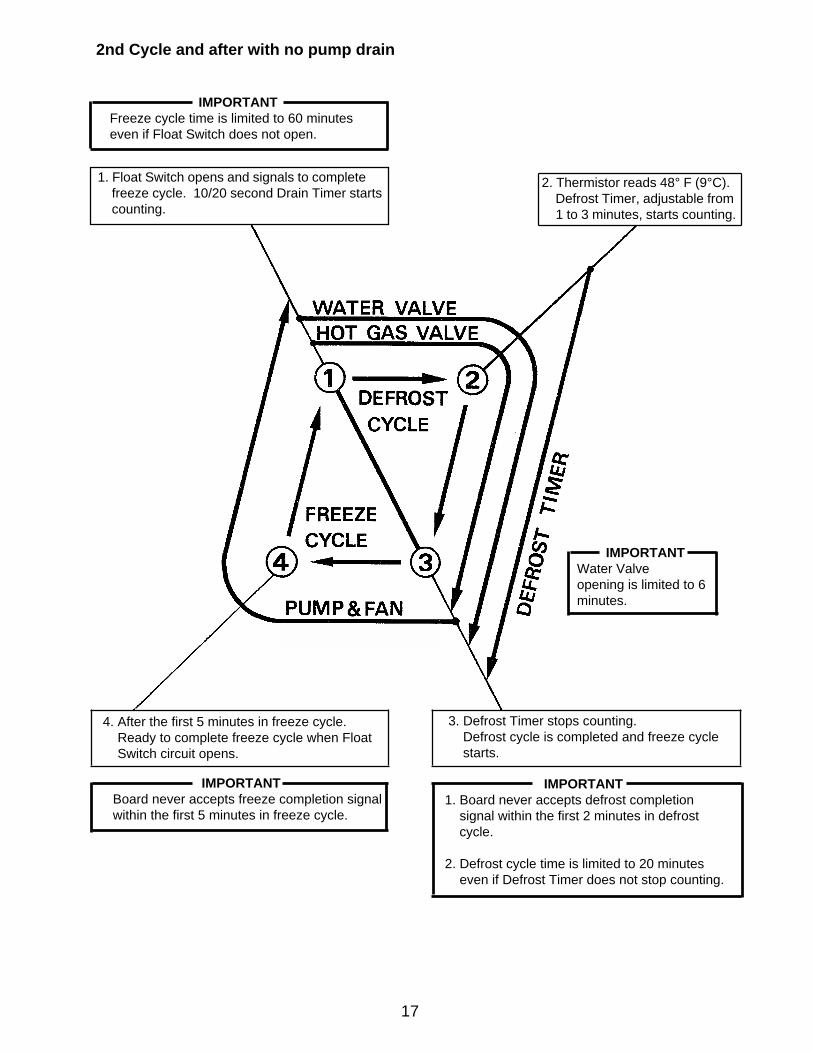
IMPORTANTFreeze cycle time is limited to 60 minuteseven if Float Switch does not open.
2nd Cycle and after with no pump drain
IMPORTANTWater Valveopening is limited to 6minutes.
4. After the first 5 minutes in freeze cycle. Ready to complete freeze cycle when Float Switch circuit opens.
3. Defrost Timer stops counting. Defrost cycle is completed and freeze cycle starts.
IMPORTANTBoard never accepts freeze completion signalwithin the first 5 minutes in freeze cycle.
IMPORTANT1. Board never accepts defrost completion signal within the first 2 minutes in defrost cycle.
2. Defrost cycle time is limited to 20 minutes even if Defrost Timer does not stop counting.
2. Thermistor reads 48° F (9°C). Defrost Timer, adjustable from 1 to 3 minutes, starts counting.
1. Float Switch opens and signals to complete freeze cycle. 10/20 second Drain Timer starts counting.

18
[d] CONTROLS AND ADJUSTMENTS
The Dip Switch is factory-adjusted to the following positions:
Switch Nos. 1 and 2:Used for adjustment of the Defrost Timer.The Defrost Timer starts counting when the Thermistor reads a certain temperatureat the Evaporator outlet.
Switch Nos. 3 and 4:Used for adjustment of the Drain Timer.When a freeze cycle is completed, the Pump Motor stops, and the icemakerresumes operation in 2 seconds. Then the Pump Motor drains the Water Tankfor the time determined by the Drain Timer. The Drain Timer also determines thetime to restrain completion of a defrost cycle, i.e. the minimum defrost time.
Switch Nos. 5 and 6:Used for adjustment of the Drain Counter.The Pump Motor drains the Water Tank at the frequency determined by the DrainCounter.
Switch Nos. 7 and 8: Used only for checking the Controller Board. Usually set in OFF position.
Switch Nos. 9 and 10:
Used for adjustment of Freeze Timer.The Freeze Timer determines maximumfreeze cycle time. Upon termination ofFreeze Timer, machine initiates theharvest cycle. After 2 consecutive timerterminations, machine will shut down,possibly indicating a problem.
DIP SWITCH NO. 1 2 3 4 5 6 7 8 9 102U0127-01 (BAF, BWF) OFF ON OFF ON OFF OFF OFF OFF NA NA2A0836-01 (BAF, BWF) OFF ON OFF ON OFF OFF OFF OFF NA NA
2A1410-01 (BAF) OFF ON OFF ON OFF OFF OFF OFF OFF OFF2A1410-01 (BWF) OFF ON OFF ON OFF OFF OFF OFF OFF ON

19
1) Defrost Control
A thermistor (Semiconductor) is used for a defrost control sensor. The resistance variesdepending on the Suction Line temperatures. The Thermistor detects the temperature ofthe Evaporator outlet to start the Defrost Timer. No adjustment is required. If necessary,check for resistance between Thermistor leads, and visually check the Thermistormounting, located on the Suction Line next to the Evaporator outlet.
Temperature (°F) Resistance (kΩ) 0 14.40110 10.61332 6.00050 3.87170 2.47490 1.633
Check a thermistor for resistance by using the following procedures:
(i) Disconnect the connector K3 on the board.
(ii) Remove the Thermistor. See “V. 10. REMOVAL AND REPLACEMENT OFTHERMISTOR.”
(iii) Immerse the Thermistor sensor portion in a glass containing ice and water for 2 or 3minutes.
(iv) Check for a resistance between Thermistor leads.Normal reading is within 3.5 to 7 kΩ. Replace the Thermistor if it exceeds the normalreading.
2) Defrost Timer
No adjustment is required under normal use, as the Defrost Timer is adjusted to thesuitable position. However, if necessary when all the ice formed on the Evaporator doesnot fall into the bin in the harvest cycle, adjust the Defrost Timer to a longer setting byadjusting the Dip Switch (No. 1 & 2) on the Controller Board.
SETTING TIMEDip Switch Dip Switch
No. 1 No. 2
OFF OFF 60 secondsON OFF 90 secondsOFF ON 120 secondsON ON 180 seconds

20
3) Drain Timer
The Drain Timer is factory-adjusted, and no adjustment is required.
SETTING TIMEDip Switch Dip Switch
No. 3 No. 4 T1 T2
OFF OFF 10 seconds 150 secondsON OFF 10 seconds 180 secondsOFF ON 10 seconds 120 secondsON ON 20 seconds 180 seconds
T1: Time to drain the Water TankT2: Time to restrain defrost completion
4) Freeze TimerCAUTION
Adjust to proper specification, or the unit may not operate correctly.
Two new dip switches numbered 9 and 10 have been added to the improved “E” board tobetter prevent possible freeze ups. These settings come factory set to the default settingof 60 min. (OFF, OFF). Check the adjustment chart published in the Tech Specs forproper settings. If the old board does not have these two dip switches, (only 8 instead of10), leave setting as OFF, OFF.
SETTING TIMEDip Switch Dip Switch
No. 9 No. 10
OFF OFF 60 min.ON OFF 70 min.OFF ON 50 min.ON ON 60 min.

21
After the 1 minute ± 5 second water supply cycle and the 2 minute ± 10 second defrostcycle, the unit should start the freeze cycle.
(ii) After the above step (i), disconnect the Float Switch leads from the Controller Boardwithin the first 5 minutes of the freeze cycle.
The unit should go into the defrost cycle after the first 5 minutes ± 20 seconds of thefreeze cycle.
(iii) Reconnect the Float Switch Connector to the Controller Board. After the first 5minutes of the freeze cycle, disconnect the Float Switch leads from the ControllerBoard.
At this point, the unit should start the defrost cycle.
(iv) After Step (iii), de-energize the unit and confirm that the Defrost Timer is in theminimum position. Disconnect the resistor from the Controller Board, and energizethe unit.After the 1 minute water supply cycle, the defrost cycle starts.Reconnect a 1.5 kΩ - 3.5 kΩ resistor to the Connector K3 (pins #1 and #2) after thefirst 2 minutes of the defrost cycle. The unit should start the freeze cycle after 1minute ± 5 seconds from the resistor connection.
5) Bin Control
CAUTION
When the ambient temperature is below 45°F, the Bin Control Thermostatoperates to stop the icemaker even if the Ice Storage Bin is empty. Whenthe Thermostat is set in the prohibited range, the icemaker operatescontinuously even if the Ice Storage Bin is filled with ice. Setting in theprohibited range might cause severe damage to the icemaker resulting infailure.
No adjustment is required under normal use, as the Bin Control is factory-adjusted.Adjust it, if necessary, so that the icemaker stops automatically within 10 seconds afterice contacts the Bin Control Thermostat Bulb.
[e] CHECKING THE CONTROLLER BOARD
1) Visually check the sequence with the icemaker operating.
2) Visually check the Controller Board by using the following procedures.
(i) Adjust the Defrost Timer to minimum position.Disconnect the Thermistor from the Controller Board.Connect a 1.5 kΩ - 3.5 kΩ resistor to the Connector K3 (pins #1 and #2), and energizethe unit.

22
[ALPINE BOARD ONLY]
3) Check the Controller Board by using test program of the Alpine Controller Board (next page).
(i) Disconnect the Connector K1 from the Controller Board. Set the Dip Switch No. 7and 8 on the Controller Board to the “ON” position, and energize the unit.
(ii) The current flows to each Relay (from X1 to X4) one after another every time the floatis raised and the contacts close. See the following chart, and check “OPEN” and“CLOSE” of Pins of the Connector K1 at each step.
(iii) If the checks are completed, turn off the icemaker, plug the Connector K1 into theController Board as before, and set the Dip Switch No. 7 and 8 to the “OFF” position.
[CONTROL PRODUCTS BOARD ONLY]
The Output Test Switch “S3” provides a relay sequence test. With power OFF, place S3on and switch power to ICE. The correct lighting sequence should be none, 2, 3, 4, 1, and4, normal sequence every 5 seconds. S3 should remain in the “OFF” position for normaloperation.

23
• TEST PROGRAM OF ALPINE CONTROLLER BOARD

24
3. SWITCHES
Control Switch
The Control Switch is located on the lower left section of the Control Box (B) when facing thefront of the machine. This switch is used to place the machine into one of three modes: “OFF”(center position), “ICE” (right position), and “WASH” (left position).
(1) “OFF”
In the “OFF” position, no power is supplied to the unit. However, to avoid any possible riskof electrical shock, disconnect the power before servicing.
(2) “ICE”
This position applies power to the unit causing the automatic ice making cycle to begin.The Water Valve is energized and the 1 minute water fill cycle starts. Refer to “II. 2 [c]SEQUENCE” for further details.
(3) “WASH”
When the Control Switch is placed in the “WASH” position, power is supplied to the PumpMotor and Cleaning Water Valve. This allows cleaning and/or sanitizing solutions (See “VI.2. CLEANING AND SANITIZING PROCEDURES”) to circulate throughout the water
system and down the inside and outside of the Evaporator plates.

25
III. TECHNICAL INFORMATION
1. WATER CIRCUIT AND REFRIGERANT CIRCUIT
[a] KM-150BAF

26
[b] KM-150BWF

27
Note: Pressure Switch - HI
KM-150BAF
Cut-out 412.5 PSIGCut-in 327.1 ±21.3 PSIG
+21.30
2. WIRING DIAGRAM
KM-150BAF, KM-150BWF
KM-150BWF
Cut-out 376.9 PSIGCut-in 270.2 ±21.3 PSIG
+21.30

28
3. TIMING CHART
*1 The Pump Motor for KM-150B series does not have drain cycle.
*2 The icemaker does not complete a defrost cycle in the first 2 or 3 minutes. See “II. 2. [d] CONTROLS ANDADJUSTMENTS.”

29
*1 The Pump Motor for KM-150B series does not have drain cycle.
*2 The icemaker does not complete a defrost cycle in the first 2 or 3 minutes. See “II. 2. [d] CONTROLS ANDADJUSTMENTS.”

30
4. PERFORMANCE DATA[a] KM-150BAF (Air-cooled)

31
[b] KM-150BWF (Water-cooled)

32
PROBLEM POSSIBLE CAUSE REMEDY[1] The icemaker a) Power Supply 1. “OFF” position. 1. Move to “ON” position will not start 2. Loose connections. 2. Tighten
3. Bad contacts. 3. Check for continuity and replace.
4. Voltage too high. 4. Check and get recommended voltage.
b) Fuse (Inside Fused 1. Blown out. 1. Check for short circuit Disconnect, if any) and replacec) Control Switch 1. “OFF” position. 1. Move to “ICE” position.
2. Bad contacts. 2. Check for continuity and replace.
d) Bin Control 1. Tripped with bin filled 1. Remove ice. Thermostat with ice.
2. Ambient temperature 2. Increase ambient too cool. temperature.3. Set too warm. 3. See “II.2.[d]
CONTROLS AND ADJUSTMENTS, 6) Bin Control.”
4. Bulb out of position. 4. Place in position.5. Bad contacts or leaks in 5. Check for continuity and bulb. replace.
e) High Pressure 1. Bad contacts. 1. Check for continuity and Control replace.f) Transformer 1. Thermal fuse blown out1. Replace.
or coil winding opened.g) Wiring to 1. Loose connections or 1. Check for continuity and Controller Board open. replace.h) Thermistor 1. Leads short-circuit or 1. See “II.2.[d] CONTROLS
open and High AND ADJUSTMENTS, 1) Temperature Safety Defrost Control.” operates. If open, unit will start but have long harvest.
i) Hot Gas Solenoid 1. Continues to open in 1. Check for power off in Valve freeze cycle and High freeze cycle and replace.
Temperature Safety operates.
j) Water Supply Line 1. Water supply off and 1. Check and get water supply cycle does recommended not finish. pressure.2. Condenser water 2. Check and get pressure too low or off recommended and Pressure Control pressure. opens and closes fre- quently to finally operate High Temperature Safety.
k) Water Solenoid 1. Mesh filter or orifice gets 1. Clean. clogged and water supply cycle does not finish.2. Coil winding opened. 2. Replace.3. Wiring to Water Valve. 3. Check for loose
connection or open, and replace.
IV. SERVICE DIAGNOSIS
1. NO ICE PRODUCTION

33
PROBLEM POSSIBLE CAUSE REMEDYl) Controller Board 1. Defective 1. See “II.2[ e ] CHECKING
CONTROLLER BOARD.”[2] Water a) Float switch 1. Connector disconnected. 1. Place in position. continues to 2. Leads opened or defective 2. Check and replace. be supplied, switch. and the ice- 3. Float does not move freely. 3. Clean or replace. maker will not b) Controller Board 1. Defective. 1. Replace. start.[3] Compressor a) Wash Switch 1. “WASH” position. 1. Move to “ICE” position. will not start 2. Bad contacts. 2. Check and replace. or operates b) High Pressure 1. Dirty Air Filter or 1. Clean. intermittently Control Condenser.
2. Ambient or condenser 2. Reduce ambient temp. water temp. too warm.3. Refrigerant overcharged. 3. Recharge.4. Condenser water pressure 4. Check and get too low or off. [Water- recommended pressure. cooled model only].5. Fan not operating. [Except 5. See chart 1 - [6]. water-cooled model].6. Refrigerant line or 6. Clean and replace Drier. components plugged.
c) Overload Protector 1. Bad contacts. 1. Check for continuity and replace.
2. Voltage too low. 2. Increase voltage.3. Refrigerant overcharged or 3. Recharge. undercharged.
d) Starter 1. Bad contacts. 1. Check and replace.2. Coil winding opened. 2. Replace.
e) Start Capacitor 1. Defective. 1. Replace.f) Magnetic Contactor 1. Bad contacts. 1. Check for continuity and
replace.2. Coil winding opened. 2. Replace.
g) Compressor 1. Wiring to Compressor. 1. Check for loose connection or open, and replace.
2. Defective. 2. Replace.3. Protector tripped. 3. Reduce temperature.
h) Controller board 1. Defective. 1. See “II.2. [ e ] CHECKING CONTROLLER BOARD.”
i) Water Regulator 1. Set too high. 1. Adjust lower.[4] Water a) Water Solenoid 1. Diaphragm does not close. 1. Check for water leaks continues to Valve with icemaker off. be supplied in b) Controller Board 1. Defective. 1. See “II.2. [ e ] CHECKING freeze cycle. CONTROLLER BOARD.”

34
PROBLEM POSSIBLE CAUSE REMEDY[5] No water a) Water Supply Line 1. Water pressure too low and 1. Check and get comes from water level in Water Tank recommended pressure. Spray Tubes. too low. Water Pump b) Water Solenoid 1. Dirty mesh filter or orifice 1. Clean. will not start, or Valve and water level in Water freeze cycle Tank too low. time is too c) Water System 1. Water leaks. 1. Check connections for short.. water leaks, and replace.
2. Clogged. 2. Clean.d) Pump Motor 1. Motor winding opened. 1. Replace.
2. Bearing worn out. 2. Replace.3. Wiring to Pump Motor 3. Check for loose
connection or open, and replace.
4. Defective Capacitor. 4. Replace.5. Defective or bound impeller. 5. Replace and clean.
e) Controller Board 1. Defective. 1. See “II.2. [ e ] CHECKING CONTROLLER BOARD.”
[6] Fan Motor will a) Fan Motor 1. Motor winding opened. 1. Replace. not start, or is 2. Bearing worn out. 2. Replace. not operating. 3. Wiring to Fan Motor. 3. Check for loose
connection or open, and replace.
4. Fan blade bound. 4. Check and replace.b) Controller Board 1. Defective. 1. See “II.2. [ e ] CHECKING
CONTROLLER BOARD.”[7] All components a) Refrigerant 1. Undercharged. 1. Check for leaks and run but no ice recharge. is produced. 2. Air or moisture trapped. 2. Replace Drier, and
recharge.b) Compressor 1. Defective valve. 1. Replace.c) Hot Gas Solenoid 1. Continues to open in freeze 1. Check and replace. Valve cycle.d) Water Solenoid 1. Stuck open. 1. Replace. Valve 2. Diaphragm bleed port 2. Clean or replace
clogged. diaphragm.e) Water Supply 1. Condenser water pressure 1. Check and get Line [Water-cooled too low or off and pressure recommended pressure. model only] control opens and closes
frequently.

35
PROBLEM POSSIBLE CAUSE REMEDY[1] Freeze cycle a) Float Switch 1. Leads short-circuit or 1. Check and replace. time is too defective switch. long. 2. Float does not move freely. 2. Clean or replace.
b) Water Solenoid 1. Diaphragm does not close. 1. Check for water leaks Valve with icemaker off.c) Controller Board 1. Defective. 1. See “II.2. [ e ] CHECKING
CONTROLLER BOARD.”[2] All ice formed a) Evaporator 1. Scaled up. 1. Clean. on Evaporator b) Water Supply Line 1. Water pressure too low. 1. Check and get does not fall recommended pressure. into bin in c) Water Solenoid 1. Dirty mesh filter or orifice. 1. Clean. harvest cycle. Valve 2. Diaphragm does not close. 2. Check for water leaks
with icemaker off.d) Ambient and/or 1. Too cool. 1. Increase temperature. water temperaturee) Thermistor 1. Out of position or loose 1. See “V. 10. REMOVAL
attachment. AND REPLACEMENT OF THERMISTOR.”
f) Controller Board 1. Defrost Timer is set too 1. Adjust longer, referring short. to “II. 2. [d] CONTROLS
AND ADJUSTMENTS, 2) Defrost Timer.”
2. Defective. 2. See "II. 2. [ e ] CHECKING CONTROLLER BOARD."
[3] Others a) Spray Tubes 1. Clogged. 1. Clean.2. Out of position. 2. Place in position.
b) Water System 1. Dirty. 1. Clean.c) Refrigerant 1. Undercharged. 1. Check for leaks and
recharge.d) Expansion Valve 1. Bulb out of position or 1. Place in position.
loose attachment.2. Defective. 2. Replace.
e) Hot Gas Solenoid 1. Coil winding opened. 1. Replace. Valve 2. Plunger does not move. 2. Replace.
3. Wiring to Hot Gas Valve. 3. Check for loose connection or open, and replace.
f) Water Supply Line 1. Too small; requires 3/8” OD 1. Increase water supply line dedicated per machine line size.
g) Water Filter 1. Flow rate too small. 1. Replace with filter with larger flow rate.
2. EVAPORATOR IS FROZEN UP

36
PROBLEM POSSIBLE CAUSE REMEDY[1] Small Cube a) Ice Cube Guide 1. Out of position. 1. Place in position.
Circulated water falls into bin.
b) See chart 1 - [5], and check water supply line, Water Solenoid Valve, water system, Pump Motor or Controller Board.
[2] Cloudy or a) See chart 2 - [1] and - [3], and check Float Switch, Water Solenoid Valve, irregular cube Controller Board, Spray Tubes, water system, refrigerant charge or Expansion
Valve.b) Spray Guide 1. Dirty. 1. Clean.c) Water Quality 1. High hardness or contains 1. Install a water filter or
impurities. softener.
4. ABNORMAL ICE
PROBLEM POSSIBLE CAUSE REMEDY
[1] Freeze cycle a) See chart 1 - [3], and check dirty Air Filter or Condenser, ambient or water time is long. temperature, water pressure or refrigerant charge.
b) See chart 2 - [1], and check Float Switch, Water Solenoid Valve or Controller Board.
[2] Harvest cycle a) See chart 2 - [2], and check Controller Board, Thermistor, Evaporator, ambient time is long and/or water temperature, water supply line or Water Solenoid Valve.
5. OTHERS
PROBLEM POSSIBLE CAUSE REMEDY[1] Icemaker will a) Bin Control 1. Set too cold. 1. Adjust warmer. not stop when Thermostat 2. Defective. 2. Replace. bin is filled with ice.[2] Abnormal a) Pump Motor 1. Bearings worn out. 1. Replace. noise b) Fan Motor 1. Bearings worn out. 1. Replace.
2. Fan blade deformed. 2. Replace fan blade.3. Fan blade does not move 3. Replace. freely.
c) Compressor 1. Bearings worn out, or 1. Replace. cylinder valve broken.2. Mounting pad out of 2. Reinstall position.
d) Refrigerant Lines 1. Rub or touch lines or other 1. Replace. surfaces.
[3] Ice in storage a) Bin Drain 1. Plugged. 1. Clean. bin often melts.
3. LOW ICE PRODUCTION

37
V. REMOVAL AND REPLACEMENT OF COMPONENTS
IMPORTANT
Ensure all components, fasteners and thumbscrews are securely in placeafter the equipment is serviced.
IMPORTANT
1. The Polyol Ester (POE) oils used in R-404A units can absorb moisturequickly. Therefore it is important to prevent moisture from entering thesystem when replacing or servicing parts.
2. Always install a new filter drier every time the sealed refrigerationsystem is opened.
3. Do not leave the system open for longer than 5 minutes when replacing or servicing parts.
1. SERVICE FOR REFRIGERANT LINES
[a] REFRIGERANT RECOVERY
The icemaker unit is provided with two Refrigerant Access Valves–one on the low-sideand one on the high-side line. Using proper refrigerant practices recover the refrigerantfrom the Access Valves and store it in an approved container. Do not discharge therefrigerant into the atmosphere.
[b] EVACUATION AND RECHARGE [R-404A]
1) Attach Charging Hoses, a Service Manifold and a Vacuum Pump to the system. Be sure to connect charging hoses to both High and Low-side Access Valves.
IMPORTANT
The vacuum level and Vacuum Pump may be the same as those forcurrent refrigerants. However, the rubber hose and gauge manifold to beused for evacuation and refrigerant charge should be exclusively for POEoils.
2) Turn on the Vacuum Pump. Never allow the oil in the Vacuum Pump to flow backward.
3) Allow the Vacuum Pump to pull down to a 29.9" Hg vacuum. Evacuating perioddepends on pump capacity.
4) Close the Low-side Valve and High-side Valve on the Service Manifold.

38
2. BRAZING
DANGER
1. Refrigerant R-404A itself is not flammable at atmospheric pressure andtemperatures up to 176° F.
2. Refrigerant R-404A itself is not explosive or poisonous. However,when exposed to high temperatures (open flames) R-404A can bedecomposed to form hydrofluoric acid and carbonyl fluoride both ofwhich are hazardous.
3. Always recover the refrigerant and store it in an approved container. Donot discharge the refrigerant into the atmosphere.
4. Do not use silver alloy or copper alloy containing Arsenic.
5. Do not use R-404A as a mixture with pressurized air for leak testing.Refrigerant leaks can be detected by charging the unit with a littlerefrigerant, raising the pressure with nitrogen and using an electronicleak detector.
Note: All brazing-connections inside the bin are clear-paint coated. Sandpaper the brazing connections before unbrazing the components. Use a good abrasive cloth
to remove coating.
5) Disconnect the Vacuum Pump, and attach a Refrigerant Service Cylinder to the High-side line. Remember to loosen the connection, and purge the air from the Hose. See the Nameplate for the required refrigerant charge. Hoshizaki recommends only virgin refrigerant or reclaimed refrigerant which meets ARI Standard No. 700-88 be used.
6) A liquid charge is recommended for charging an R-404A system. Invert the servicecylinder. Open the High-side, Service Manifold Valve.
7) Allow the system to charge with liquid until the pressures balance.
8) If necessary, add any remaining charge to the system through the Low-side. Use a throttling valve or liquid dispensing device to add the remaining liquid charge through the Low-side access port with the unit running.
9) Close the two Refrigerant Access Valves, and disconnect the Hoses and ServiceManifold.
10) Cap the Access Valves to prevent a possible leak.

39
3. REMOVAL AND REPLACEMENT OF COMPRESSOR
IMPORTANT
Always install a new Drier every time the sealed refrigeration system isopened. Do not replace the Drier until after all other repair or replacementhas been made.
Note: When replacing a Compressor with a defective winding, be sure to install the newStart Capacitor and Start Relay supplied with the replacement Compressor. Dueto the ability of the POE oil in the compressor to absorb moisture quickly, theCompressor must not be opened more than 15 minutes for replacement orservice. Do not mix lubricants of different compressors even if both are chargedwith R-404A, except when they use the same lubricant.
1) Turn off the power supply and unplug the icemaker.
2) Remove the Front Panel and slide out the refrigeration base.
3) Recover the refrigerant and store it in an approved container.
4) Remove the Terminal Cover on the Compressor, and disconnect the CompressorWiring.
5) Remove the Discharge and Suction Pipes using brazing equipment.
6) Remove the Hold-down Bolts, Washers and Rubber Grommets.
7) Slide and remove the Compressor. Unpack the new Compressor package. Installthe new Compressor.
8) Attach the Rubber Grommets of the prior Compressor.
9) Sandpaper the Suction, Discharge and Process Pipes.
10) Place the Compressor in position, and secure it using the Bolts and Washers.
11) Remove plugs from the Suction, Discharge and Process Pipes.
12) Braze the Process, Suction and Discharge lines (Do not change this order), whilepurging with nitrogen gas flowing at the pressure 3 - 4 PSIG.
13) Install the new Filter Drier.
14) Check for leaks using nitrogen gas (140 PSIG) and soap bubbles.

40
15) Evacuate the system, and charge it with refrigerant. See the Nameplate for therequired refrigerant charge.
16) Connect the Terminals, and replace the Terminal Cover in its correct position.
17) Slide in the refrigeration base and replace the Front Panel in its correct position.
18) Plug in the icemaker, and turn on the power supply.
4. REMOVAL AND REPLACEMENT OF DRIER
IMPORTANT
Always install a new Drier every time the sealed refrigeration system isopened. Do not replace the Drier until after all other repair or replacementhas been made.
1) Turn off the power supply and unplug the icemaker.
2) Remove the panels.
3) Recover the refrigerant and store it in an approved container.
4) Remove the Drier.
5) Install the new Drier, with the arrow on the Drier, in the direction of the refrigerant flow. Use nitrogen gas at the pressure of 3 - 4 PSIG when brazing the tubings.
6) Check for leaks using nitrogen gas (140 PSIG) and soap bubbles.
7) Evacuate the system, and charge it with refrigerant. See the Nameplate for the required refrigerant charge.
8) Replace the panels in their correct position.
9) Plug in the icemaker, and turn on the power supply.

41
5. REMOVAL AND REPLACEMENT OF EXPANSION VALVE
IMPORTANT
Sometimes moisture in the refrigerant circuit exceeds the Drier capacityand freezes up at the Expansion Valve. Always install a new Drier everytime the sealed refrigeration system is opened. Do not replace the Drieruntil after all other repair or replacement has been made.
1) Turn off the power supply.
2) Remove the Front Panel and slide out the refrigeration base.
3) Recover the refrigerant and store it in an approved container.
4) Remove the insulation and the Expansion Valve Bulb on the suction line.
5) Remove the Expansion Valve Cover, and disconnect the Expansion Valve using brazing equipment.
6) Braze the new Expansion Valve, with nitrogen gas flowing at the pressure of 3 - 4PSIG.
WARNING
1. Do not heat the wall. Place a steel barrier for protection.
2. Always protect the valve body by using a damp cloth to prevent the valvefrom overheating. Do not braze with the valve body exceeding 250°F.
7) Install the new Drier.
8) Check for leaks using nitrogen gas (140 PSIG) and soap bubbles.
9) Evacuate the system, and charge it with refrigerant. See the Nameplate for the required refrigerant charge.
10) Attach the Bulb to the suction line in position. Be sure to secure it with clampsand to insulate it.
11) Place the new set of Expansion Valve Covers in position.
12) Replace the panels in their correct position.
13) Plug in the icemaker, and turn on the power supply.

42
6. REMOVAL AND REPLACEMENT OF HOT GAS VALVE
CAUTION
Always use a copper tube of the same diameter and length when replacingthe hot gas lines; otherwise the performance may be reduced.
IMPORTANT
Always install a new Drier every time the sealed refrigeration system isopened. Do not replace the Drier until after all other repair or replacementhas been made.
1) Turn off the power supply and unplug the icemaker.
2) Remove the panels.
3) Recover the refrigerant and store it in an approved container.
4) Remove the screw and the Solenoid.
5) Disconnect the Hot Gas Valve using brazing equipment.
6) Install the new valve.
WARNING
Always protect the valve body by using a damp cloth to prevent the valvefrom overheating. Do not braze with the valve body exceeding 250°F.
7) Install the new Drier.
8) Check for leaks using nitrogen gas (140 PSIG) and soap bubbles.
9) Evacuate the system, and charge it with refrigerant. See the Nameplate for the required refrigerant charge.
10) Cut the leads of the Solenoid allowing enough lead length to reconnect using closed end connectors.
11) Connect the new Solenoid leads.
12) Attach the Solenoid to the valve body, and secure it with a screw.
13) Slide in the refrigeration base and replace the Front Panel in its correct position.
14) Plug in the icemaker, and turn on the power supply.

43
7. REMOVAL AND REPLACEMENT OF EVAPORATOR
IMPORTANT
Always install a new Drier every time the sealed refrigeration system isopened. Do not replace the Drier until after all other repairs or replacementshave been made.
1) Turn off the power supply, and unplug the icemaker.
2) Remove the panels and the Top Insulation over the Evaporator.
3) Recover the refrigerant and store it in an approved container.
4) Remove the Spray Tubes and the Insulations at the "U" shaped notch where the refrigeration tubings go through the molded chassis.
5) Remove the Insulation Tube, and disconnect the Evaporator Inlet Tubing at the Tee next to the Expansion Valve.
6) Remove the screws holding the Evaporator to the plastic Rear Panel.
7) Lift up the Evaporator, and disconnect the Evaporator Outlet Tubing.
8) Install the new Evaporator.
9) Install the new Drier.
10) Check for leaks using nitrogen gas (140 PSIG) and soap bubbles.
11) Evacuate the system, and charge it with refrigerant. See the Nameplate for therequired refrigerant charge.
12) Replace the removed parts in the reverse order of which they were removed.
13) Replace the Top Insulation and the panels in their correct position.
14) Plug in the icemaker, and turn on the power supply.

44
8. REMOVAL AND REPLACEMENT OF WATER REGULATING VALVE -WATER-COOLED MODEL ONLY
IMPORTANT
Always install a new Drier every time the sealed refrigeration system isopened. Do not replace the Drier until after all other repair or replacementhas been made.
1) Turn off the power supply, and unplug the icemaker.
2) Close the Water Supply Line Shut-off Valve.
3) Remove the Front Panel and slide out the refrigeration base.
4) Recover the refrigerant and store it in an approved container.
5) Disconnect the Capillary Tube at the Condenser outlet using brazing equipment.
6) Disconnect the Flare-connections of the valve.
7) Remove the screws and the valve from the Bracket.
8) Install the new valve, and braze the Capillary Tube.
9) Install the new Drier.
10) Check for leaks using nitrogen gas (140 PSIG) and soap bubbles.
11) Evacuate the system, and charge it with refrigerant. See the Nameplate for the required refrigerant charge.
12) Connect the Flare-connections.
13) Open the Water Supply Line Shut-off Valve.
14) Check for water leaks.
15) Slide in the refrigeration base and replace the Front Panel in its correct position.
16) Plug in the icemaker, and turn on the power supply.

45
9. ADJUSTMENT OF WATER REGULATING VALVE - WATER-COOLEDMODEL ONLY
The Water Regulating Valve (also called “WATER REGULATOR”) is factory-adjusted.No adjustment is required under normal use. Adjust the Water Regulator, if necessary,using the following procedures.
1) Attach a pressure gauge to the high-side line of the system or prepare a thermometer to check for the condenser drain temperature.
2) Rotate the adjustment screw by using a flat blade screwdriver, so that the pressuregauge shows 270 PSIG or the thermometer reads 104-115 °F, 5 minutes after afreeze cycle or icemaking process starts. When the pressure exceeds 270 PSIG, orthe condenser drain temperature exceeds 115 ° F, rotate the adjustment screwcounterclockwise. See Fig. 1.
3) Check that the pressure or the condenser drain temperature holds a stable setting.
Fig. 1

46
Foam Insulation Thermistor Holder
Thermistor Lead Cable Tie
Fig. 2
10. REMOVAL AND REPLACEMENT OF THERMISTOR
CAUTION
1. Fragile, handle very carefully.
2. Always use a recommended sealant (High Thermal Conductive Type),Model KE4560RTV manufactured by SHINETSU SILICONE, Part Code60Y000-11, or Part Code 4A0683-01 or equivalent.
3. Always use a recommended foam insulation (Non-absorbent Type) orequivalent.
4. Do not shorten or cut the Thermistor leads when installing it.
1) Turn off the power supply, and unplug the icemaker.
2) Remove the panels.
3) Remove the Control Box Cover at the rear of the unit.
4) Disconnect the Thermistor leads from the K3 Connector on the Controller Board.
5) Remove the Plastic Cable Ties, Foam Insulation, Thermistor Holder and Thermistor. See Fig. 2.
6) Scrape away the old sealant on the Thermistor Holder and the Suction Pipe.
7) Wipe off moisture or condensation on the Suction Pipe.
8) Smoothly apply recommended sealant (KE4560RTV, Part Code 60Y000-11) to theThermistor Holder concave.
9) Attach the new Thermistor to the Suction Pipe very carefully to prevent damage tothe leads. Secure it using the Thermistor Holder and recommended foaminsulation.
10) Secure the insulation using the Plastic Cable Ties.

47
11. REMOVAL AND REPLACEMENT OF FAN MOTOR - EXCEPTWATER-COOLED MODEL
1) Turn off the power supply, and unplug the icemaker.
2) Remove the Front Panel and slide out the refrigeration base.
3) Remove the screws and the Fan Shroud.
4) Remove the Fan Blade.
5) Remove the closed end connectors of the Fan Motor.
6) Remove the Fan Motor Bracket.
7) Remove the Fan Motor from the Bracket.
8) Install the new Fan Motor, and replace the removed parts in the reverse order ofwhich they were removed.
9) Slide in the refrigeration base and replace the Front Panel in its correct position.
10) Plug in the icemaker, and turn on the power supply.
12. REMOVAL AND REPLACEMENT OF WATER VALVE
1) Turn off the power supply, and unplug the icemaker.
2) Close the Water Supply Line Shut-off Valve.
3) Disconnect the water supply piping.
4) Remove the Top Panel.
5) Disconnect the Valve Outlet Tubing by releasing the Clamp.
6) Disconnect the Terminals from the Water Valve.
11) Connect the Thermistor leads through the bushing of the Control Box to the K3Connector on the Controller Board.
Note: Do not cut the leads of the Thermistor while installing it.
12) Replace the Control Box Cover and the panels in their correct positions.
13) Plug in the icemaker, and turn on the power supply.

48
13. REMOVAL AND REPLACEMENT OF PUMP MOTOR
Note: When replacing a Pump Motor with defective winding, it is recommended that anew capacitor be installed.
1) Turn off the power supply, and unplug the icemaker.
2) Remove the Top Panel and Rear Panel.
3) Open the Bin Door.
4) Drain the Water Tank by removing the Rubber Tube and thumbscrew and pulling theTank forward and slightly down.
5) Release the Hose Clamp, and disconnect the Hose from the Spray Tube.
6) Remove the closed end connectors of the Pump Motor leads.
7) Remove the screw and the Pump Motor Bracket.
8) Lift up the Pump Motor with the Pump Motor Bracket.
9) Release the Hose Clamp, and disconnect the Hose for the Cleaning Water Valve.
10) Remove the four screws and the Pump Motor.
11) Install the new Pump Motor, and replace the removed parts in the reverse order of whichthey were removed.
7) Remove the Fitting and the Gasket.
8) Release the Hose Clamp, and disconnect the Hose.
9) Remove the Water Valve from the Rear Panel.
10) Install the new Water Valve, and replace the removed parts in the reverse order of which they were removed.
11) Replace the Top Panel in its correct position.
12) Open the Water Supply Line Shut-off Valve.
13) Plug in the icemaker, and turn on the power supply.

49
14. REMOVAL AND REPLACEMENT OF FLOAT SWITCH
1) Go through the steps 1) through 7) in “13. REMOVAL AND REPLACEMENT OFPUMP MOTOR.”
2) Remove the connectors of the Float Switch.
3) Remove the screw and the Float Switch Bracket.
4) Remove the two screws and the Float Switch.
5) Take off the Hose sleeving the Float Switch leads.
6) Sleeve the leads of the new Float Switch with the Hose.
7) Install the new Float Switch, and replace the removed parts in the reverse order of which they were removed.
8) Go through the steps 12) through 14) in “13. REMOVAL AND REPLACEMENT OF PUMP MOTOR.”
15. REMOVAL AND REPLACEMENT OF SPRAY TUBE
1) Turn off the power supply, and unplug the icemaker.
2) Remove the Top Panel and Top Insulation.
3) Disconnect the Hoses.
4) Lift off the Spray Tube.
5) Install the new Spray Tube.
Note: Place the Spray Tube so that the holding tabs on both sides are in position.
6) Connect the Hoses.
7) Replace the Top Insulation and Top Panel in their correct positions.
8) Plug in the icemaker, and turn on the power supply.
12) Close the Bin Door.
13) Replace the panels in their correct positions.
14) Plug in the icemaker, and turn on the power supply.

50
VI. CLEANING AND MAINTENANCE INSTRUCTIONS1. PREPARING THE ICEMAKER FOR LONG STORAGE
IMPORTANT
Ensure all components, fasteners and thumbscrews are securely in placeafter any maintenance or cleaning is done to the equipment.
WARNING
When shutting off the icemaker for an extended time, drain out all water fromthe water tank and remove the ice from the Storage Bin. The Storage Binshould be cleaned and dried. Drain the icemaker to prevent damage to thewater supply line at sub-freezing temperatures, using air or carbon dioxide.Shut off the icemaker until the proper ambient temperature is resumed.
• When the icemaker is not used for two or three days, it is sufficient to only move the Control Switch to the “OFF” position, unless the icemaker will be at sub-freezing temperatures.
[1] On water-cooled model only, first remove the water from the water-cooled condenser:
1) Remove the Front Panel.
2) Move the Control Switch, on the Control Box, to the “OFF” position.
3) Wait 3 minutes.
4) Move the Control Switch to the “ICE” position.
5) Allow 5 minutes for the icemaker to fill with water and the Water Pump to startopening.
6) Close the Water-cooled Condenser Water Supply Line Shut-off Valve.
7) Open the Drain Valve for the water-cooled condenser water supply line.
8) Allow the line to drain by gravity.
9) Attach compressed air or carbon dioxide supply to the Condenser Water Line DrainValve.
10) Quickly blow the water-cooled condenser out using compressed air or carbondioxide until water stops coming out.

51
[2] Remove the water from the potable water supply line:
1) Remove the Front Panel. (Except water-cooled model)
2) Move the Control Switch, on the Control Box, to the “OFF” position.
3) Wait 3 minutes.
4) Close the Potable Water Supply Line Shut-off Valve and open the Potable Water SupplyLine Drain Valve.
5) Allow the line to drain by gravity.
6) Attach compressed air or carbon dioxide supply to the Potable Water Line Drain Valve.
7) Move the Control Switch to the “ICE” position.
8) Blow the potable water line out using compressed air or carbon dioxide.
[3] Drain the Potable Water Tank:
1) Disconnect the power supply.
2) Move the Control Switch to the “OFF” position.
3) Open the Door.
4) Remove the Cube Guide and the Overflow Pipe to drain the Water Tank. See Fig. 3
5) Place the Overflow Pipe and the Cube Guide in their correct positions.
6) Remove all ice from the Storage Bin, and clean the Storage Bin.
7) Shut the Door.
8) Replace the Front Panel in its correct position.
9) Close the Drain Valve.

52
Fig. 3
2. CLEANING AND SANITIZING PROCEDURES
IMPORTANT
Ensure all components, fasteners and thumbscrews are securely in placeafter any maintenance or cleaning is done to the equipment.
WARNING
1. Hoshizaki recommends cleaning this unit at least once a year. Morefrequent cleaning, however, may be required in some existing waterconditions.
2. To prevent injury to individuals and damage to the icemaker, do not useammonia type cleaners.
3. Always wear liquid-proof gloves for safe handling of the cleaning andsanitizing solutions. This will prevent irritation in case the solutions comeinto contact with skin.
[a] CLEANING PROCEDURE
1) Dilute approximately 5 fl. oz. (148 ml.) of recommended cleaner, Hoshizaki “ScaleAway” or “Lime-A-Way” (Economics Laboratory, Inc.) with 1 gal. (3.8 l.) of warm water.
2) Remove the Front Panel.
3) Remove all ice from the Evaporator and the Storage Bin.
Note: To remove cubes on the Evaporator, move the Control Switch,on the Control Box, to the “OFF” position and move it back to the “ICE” position after 3 minutes. The defrost cycle starts, and thecubes will be removed from the Evaporator.
4) Move the Control Switch to the “OFF” position. Open the Door.
5) Remove the Cube Guide and the Overflow Pipe to drain the Water Tank. See Fig. 3. Place the Overflow Pipe in position.
6) Pour the cleaning solution into the Water Tank.
7) Place the Cube Guide in position.

53
8) Move the Control Switch to the “WASH” position. Shut the Door.
9) After 30 minutes, move the Control Switch to the “OFF” position.
10) Remove the Cube Guide and the Overflow Pipe to drain the Water Tank. Place theOverflow Pipe and Cube Guide in their correct positions.
11) Move the Control Switch to the “ICE” position to fill the Water Tank with water.
12) After 3 minutes, move the Control Switch to the “OFF” position.
13) Move the Control Switch to the “WASH” position.
14) After 5 minutes, move the Control Switch to the “OFF” position.
15) Remove the Cube Guide and the Overflow Pipe to drain the Water Tank. Place theOverflow Pipe and Cube Guide in their correct positions.
16) Repeat the above steps 11) through 15) three more times to rinse thoroughly.
17) Remove one end of the Tank Drain Hose and remove the Thumbscrew at the front of theWater Tank. Remove the Water Tank by pulling it toward you slightly and lowering it.See Fig. 4.
18) Remove the Water Tank Brackets and the Thermostat Bracket from the Bin by removing the Thumbscrews.
19) Dilute approximately 5 fl. oz. (148 ml.) of recommended cleaner Hoshizaki “Scale Away”or “Lime-A-Way” (Economics Laboratory, Inc.) with 1 gal. (3.8 l.) of water.
20) Wash the bin liner, the Thermostat Bracket, the Water Tank Brackets and the WaterTank by using a nylon scouring pad, brushes and the cleaning solution.
21) Rinse them thoroughly with water.
Fig. 4

54
[b] SANITIZING PROCEDURE - Following Cleaning Procedure
1) Dilute a 5.25% Sodium Hypochlorite solution (chlorine bleach) with water. [Add 0.5 fl. oz.(15 ml.) of sanitizer to 1 gal. (3.8 l.) of water.]
2) Wash the bin liner, the Thermostat Bracket, the Water Tank Brackets and the Water Tank using the above sanitizing solution.
3) Rinse the above parts thoroughly with water.
4) Place the Thermostat Bracket, the Water Tank Brackets, the Water Tank and the Tank Drain Hose in their correct positions.
5) Remove the Cube Guide.
6) Pour the sanitizing solution into the Water Tank.
7) Place the Cube Guide in its correct position.
8) Move the Control Switch to the “WASH” position.
9) Shut the Door.
10) After 15 minutes, move the Control Switch to the “OFF” position.
11) Open the Door.
12) Remove the Cube Guide and the Overflow Pipe to drain the Water Tank. Place theOverflow Pipe and the Cube Guide in position.
13) Repeat the above steps 11) through 15) in “[a] CLEANING PROCEDURE” two times torinse thoroughly.
14) Flush the Storage Bin with water.
15) Move the Control Switch to the “ICE” position, and start the automatic icemakingprocess.
16) Place the Front Panel in position, and shut the Door.

55
3. MAINTENANCE
IMPORTANT
This icemaker must be maintained individually, referring to the instructionmanual and labels provided with the icemaker.
1) Stainless Steel Exterior
To prevent corrosion, wipe the exterior occasionally with a clean and soft cloth. Usea damp cloth containing a neutral cleaner to wipe off oil or dirt build up.
2) Storage Bin and Scoop
• Wash your hands before removing ice. Use the plastic scoop provided.
• The Storage Bin is for ice use only. Do not store anything else in the bin.
• Keep the scoop clean. Clean it by using a neutral cleaner and rinse thoroughly.
• Clean the bin liner by using a neutral cleaner. Rinse thoroughly after cleaning.
3) Air Filter (Air-cooled model only)
A plastic mesh air filter removes dirt or dust from the air, and keeps the Condenserfrom getting clogged. As the filter gets clogged, the icemaker’s performance will bereduced. Check the filter at least twice a month. When clogged, use warm water anda neutral cleaner to wash the filter.
4) Condenser (Air-cooled model only)
Check the Condenser once a year, and clean if required by using a brush or vacuumcleaner. More frequent cleaning may be required depending on the location of theicemaker.