creep of prestressing steels in fire - wordpress.com · gales, j., robertson, l., and bisby, l....
TRANSCRIPT
GALES, J., ROBERTSON, L., AND BISBY, L. (2016) CREEP OF PRESTRESSING STEELS IN
FIRE. FIRE AND MATERIALS. 40, 875–895. DOWNLOAD AT
HTTP://ONLINELIBRARY.WILEY.COM/DOI/10.1002/FAM.2345/EPDF
CREEP OF PRESTRESSING STEELS IN FIRE, OPEN ACCESS VERSION | Download at
http://onlinelibrary.wiley.com/doi/10.1002/fam.2345/epdf
Creep of Prestressing Steels in Fire
John Gales1, Lucie Robertson2, and Luke Bisby3
1 Assistant Professor, Carleton University, Ottawa, Canada, [email protected] 2 Graduate Engineer, Mott MacDonald, Glasgow, United Kingdom,
[email protected] 3 Arup Professor of Fire and Structures, University of Edinburgh, Edinburgh, United Kingdom,
ABSTRACT
When prestressing steel (PS) is applied as continuous unbonded tendons within concrete, as in the
case of post-tensioned (PT) construction, localized damage to the tendons may affect the integrity
of the entire structure. When fire exposed, unbonded PT concrete structures are prone to tendon
rupture due to a complex relaxation and strength reduction relationship influenced by high
temperature PS creep. Explicit consideration of creep is necessary for the fire safe design of such
buildings. High temperature PS creep has received limited research: few models can be used within
the expected service stress range; none reliably model tertiary creep; and no studies are available
investigating the influences of metallurgy on high temperature PS creep. A BS 5896 PS creep model
is developed and validated. This model is used to provide PS failure insights at high temperatures.
This understanding can be used to build validated models of structural fire experiments on PT
concrete structural elements and to develop defensible, validated structural models that are
essential towards performance based structural fire design of such systems. Finally, the high
temperature creep performance of equivalent PS from different mills is compared, demonstrating
strong influence of manufacturing and alloying techniques used. Future research is discussed.
Key words: High temperature creep, prestressing steel, optical strain measurement,
necking, chemical composition, metallurgy.
Notation
a,b,c.d – empirical creep constants
– creep rate (mm/mm per time)
– strain (unitless)
cr,o – Primary creep value (unitless)
t – thermal expansion strain (unitless)
cr – creep strain (unitless)
fpu – Ultimate strength (MPa)
θ – Temperature compensated time (hours)
– Stress (MPa)
t – Time (hours)
T – Temperature (K)
Q – Activation energy (K)
Z – Zener-Hollomon Parameter (hrs-)
GALES, J., ROBERTSON, L., AND BISBY, L. (2016) CREEP OF PRESTRESSING STEELS IN
FIRE. FIRE AND MATERIALS. 40, 875–895. DOWNLOAD AT
HTTP://ONLINELIBRARY.WILEY.COM/DOI/10.1002/FAM.2345/EPDF
CREEP OF PRESTRESSING STEELS IN FIRE, OPEN ACCESS VERSION | Download at
http://onlinelibrary.wiley.com/doi/10.1002/fam.2345/epdf
1. Introduction
Prestressing steel (PS) is increasingly favoured for reinforcing highly optimized, modern
concrete flat slabs owing to various sustainability, economic, and constructability benefits.
In the popular construction technique of unbonded post-tensioned (UPT) concrete,
prestressing steel is cast inside concrete structural elements in continuous strands or
tendons, placed inside lubricated draped ducts which leaves the PS unbonded from the
concrete, stressed and anchored only at its ends using special anchors. Whilst highly
efficient and effective at ambient temperature, the continuity of UPT steel over multiple
bays in a concrete structure can have potential drawbacks – particularly during fire.
Localized heating of the prestressing steel, as is likely to occur during real building fires
(due to concrete cover spalling, fire compartmentation, travelling fires, ceiling jets, or
tendon drape, etc), could result in tendon rupture and would affect slab capacity and
integrity distant from the fire [1]. Recent experiments on stressed UPT tendons of realistic
length under localized heating have confirmed that thermally-induced rupture can occur at
temperatures well below those at which uniformly heated, stressed UPT tendons would fail
[2]. The likelihood of rupture of UPT steel tendons at elevated temperature within a
concrete structure depends on complex interactions between thermally induced strength
reductions and tendon stress variations caused by time, stress, and temperature dependent
irrecoverable creep deformations. An accurate and robust method for predicting creep
deformation and rupture for any possible transient heating regime is needed to accurately
predict the fire resistance of UPT structures.
A computational model for predicting high temperature stress variations in locally-
heated unbonded and stressed prestressing steel tendons has previously been developed;
this model can reasonably predict observed deformation trends [3][4]. However, this
modelling was forced to assume outdated input parameters originating from the 1970s [5],
and these were hypothesized as not reflecting the metallurgy or processing of modern
prestressing steels, leading to significant overestimation of prestress relaxation [3]. The
authors have recently presented new creep model input parameters based on a limited data
set and stress range for a specific ASTM A416 prestressing steel, with promising results
[6]. However, the prior was not able to provide a creep model that could be used over the
full range of relevant stresses due to the inapplicability of the empirically defined model
input parameters. The study also discussed the influence of necking on creep failure, but
provided no quantified analysis of this. Additionally, the effects of changes in
microstructure which occur with increased temperature were not explicitly considered [7],
nor were any subtle effects from manufacturing or alloying processes which could have
influenced the microstructure of the steel and thereby its performance at high temperature.
This paper represents a logical continuation of the authors’ prior work on high
temperature creep of prestressing steel. The high temperature deformation behaviour of
prestressing steel manufactured in Europe and fabricated according to the BS 5896 standard
[8] is tested and analysed in detail; whereas all prior work has been on North American
ASTM A416 steel [7][9]. A testing regime using both steady-state and transient thermal
uniaxial tensile tests has been undertaken using a novel non-contact optical strain
measurement technology based on Digital Image Correlation (DIC) [6]. The current study
primarily aims to explore the assumptions used in contemporary creep theory by providing

GALES, J., ROBERTSON, L., AND BISBY, L. (2016) CREEP OF PRESTRESSING STEELS IN
FIRE. FIRE AND MATERIALS. 40, 875–895. DOWNLOAD AT
HTTP://ONLINELIBRARY.WILEY.COM/DOI/10.1002/FAM.2345/EPDF
CREEP OF PRESTRESSING STEELS IN FIRE, OPEN ACCESS VERSION | Download at
http://onlinelibrary.wiley.com/doi/10.1002/fam.2345/epdf
novel insights into accelerating creep leading to failure – so-called ‘Tertiary’ creep. A
validation exercise for the newly developed creep parameters is presented and the resulting
creep model’s limitations are discussed.
Available creep parameters for any steel are widely assumed to apply equally to all
similar prestressing steels sourced from different manufacturers; however, fabrication and
composition differences from producer to producer may influence respective steels’ creep
responses, particularly at high temperatures and stress levels. This paper therefore
considers the creep behaviour of “equivalent” grades of prestressing steel sourced from
three separate steel mills: one European (BS 5896 [8]), one North American (ASTM A416
[9]), and one Australasian (AS/NZS 4672 [10]). The creep behaviour of these specific
steels is also compared against available results from tests on prestressing steel from the
1970s, fabricated according to ASTM A421 [11], and presented by Harmathy and Stanzak
[5]. An exploratory modelling exercise is then undertaken to illustrate the importance of
using specific creep parameters for the prestressing steel that is actually being used. The
paper concludes with recommendations for future work to improve creep parameters for
modelling prestressing steel deformation and rupture in fire.
Defensible performance based structural fire engineering designs of UPT concrete
structures require a proper understanding of material response to heating [12][13]. Several
high temperature tests on continuous post-tensioned concrete floors were previously
performed by the authors [14][15][16]. The tests were densely instrumented and included
many complexities of real UPT concrete construction, including a single draped
monostrand BS 5896 prestressing strand. The tests revealed highly complex mechanical
response to high temperature [15], and the mechanisms responsible for this complexity
were shown to be highly dependent on the high temperature stress relaxation of the
prestressing steel due to creep. The BS 5896 prestressing steel considered herein is from
the same batch used to construct those floor assemblies. The stock also comes from the
same mill and identical fabrication processes used in the the Bailey and Ellobody post-
tensioned slab test series [17][18]. Accordingly, characterizing the mechanical and creep
response of this steel stock is essential to defensibly build structural response models of
these heated floor tests, as well as the eventual goal of modelling an entire post-tensioned
concrete structure in fire.
2. Creep theory
The current study utilizes the well-known Harmathy creep model [5][19]. This model was
chosen so as to provide consistency with previous studies by the authors, and also because
it is widely applied in practice [20]. To provide context for the reader, the current state-of-
the-art in creep theory, with primary reference to the Harmathy model, is given in this
section.
2.1 Background
High temperature creep strain (cr) is an irrecoverable deformation that depends on stress,
temperature, and time, as well as various micro-structural and metallurgical characteristics.
Creep can be observed in tests either using transient (i.e. load the sample to a chosen stress
level, maintain the load constant, and then heat at constant rate) or steady state (i.e. heat to
GALES, J., ROBERTSON, L., AND BISBY, L. (2016) CREEP OF PRESTRESSING STEELS IN
FIRE. FIRE AND MATERIALS. 40, 875–895. DOWNLOAD AT
HTTP://ONLINELIBRARY.WILEY.COM/DOI/10.1002/FAM.2345/EPDF
CREEP OF PRESTRESSING STEELS IN FIRE, OPEN ACCESS VERSION | Download at
http://onlinelibrary.wiley.com/doi/10.1002/fam.2345/epdf
a chosen temperature, then maintain constant temperature and load the sample) test
conditions. Tests are typically controlled using constant load, since true stress cannot be
directly measured in real time and is therefore ‘assumed’, sometimes accounting for
volumetric changes during testing (more often not). By plotting the measured cr (after
careful removal of strains due to thermal expansion and mechanical strains due to elastic
modulus reduction on heating) a sigmoid (S-shaped) curve can be plotted with respect to a
lumped time-temperature parameter that is commonly referred to as ‘Temperature
Compensated Time’, θ. Invoking an empirical coefficient Q, known as the ‘activation
energy’ for creep and measured in degrees Kelvin, θ can be described using an Arrhenius
equation as:
[1]
where t is the duration, in hours, of an analysis time step [4][20], and T is the temperature
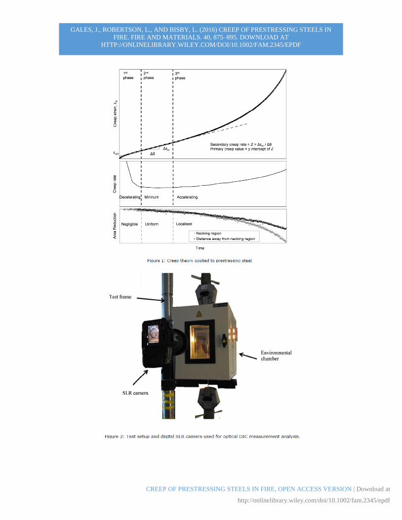
in degrees Kelvin. A typical example of an cr versus θ curve (i.e. a ‘creep curve’) for
prestressing steel is given in Figure 1(a). The trends in Figure 1 were derived from real test
data however the magnitudes have been omitted for illustrative purposes.
The classical creep curve has three distinct phases: (1) a Primary phase
characterised by a decreasing creep deformation rate and dominated by strain hardening,
in which the strain rate progressively decreases as the hardening process increases due to
counteraction from dislocations within the grain structure of the steel; (2) a Secondary
phase described by a ‘steady’ minimum straining rate, and resulting from the formation
and growth of voids (in the form of cavities, pores, and/or cracking) within the grain
microstructure; and which (3) eventually causes the straining rate under constant load to
accelerate (Figure 1(b)) as ‘runaway’ strain during a final Tertiary phase. The voids are
theorized to form along grain boundaries and may be influenced by material impurities,
dislocation breakthrough, or distortion of the grains [21]. The acceleration of creep during
the Tertiary phase eventually leads to failure [22].
Defining the point of initiation of Tertiary creep is challenging in practice and this
issue is uniquely treated in the current paper. The classical definition of the beginning of
Tertiary creep is the moment at which the minimum creep rate is observed during the
Secondary phase [23]. By determining the minimum creep rate for an cr versus θ plot, a
Zener-Hollomon parameter, Z, can be derived (in hrs-1) [24]. This may be approximated by
determining the slope of the approximately linear Secondary creep phase. A linear tangent
to the Secondary phase will intercept the vertical-axis at the so-called Primary creep value,
cr,o. The extraction of Z and cr,o from a sustained stress uniaxial creep test is illustrated in
Figure 1(a). In fire engineering design [20][25] these parameters can be used to predict the
amount of creep during the Primary and Secondary creep phases, but not during the Tertiary
phase. Equation 2 is often used to predict cr for steel as:
[2]
tTQ dte
0
/
0,0, 2cosh
2ln
cr
Z
cr
cr
GALES, J., ROBERTSON, L., AND BISBY, L. (2016) CREEP OF PRESTRESSING STEELS IN
FIRE. FIRE AND MATERIALS. 40, 875–895. DOWNLOAD AT
HTTP://ONLINELIBRARY.WILEY.COM/DOI/10.1002/FAM.2345/EPDF
CREEP OF PRESTRESSING STEELS IN FIRE, OPEN ACCESS VERSION | Download at
http://onlinelibrary.wiley.com/doi/10.1002/fam.2345/epdf
2.2 Activation energy, Q
The advantage of Equations 1 and 2 is that two steady state creep curves at different
temperatures and the same loading could overlap with respect to θ [19]. Thus, transient and
steady state creep tests at the same loading level can also overlap, as was verified
previously in [6]. This idea can be used to advantage if the temperature compensated time
reasoning suggested in Equation 1 is valid, since a steady state test can take many hours to
complete, whereas a shorter transient test may yield equally useful parameters in a much
shorter time. The equivalency of tests should be assured by proper derivation of Q, which
is an essential parameter in defining θ. Two techniques [22][26] may be used to derive Q
for a given prestressing steel.
Several creep tests performed at the same load but at different temperatures could
be used to derive an accurate value of Q. Using this technique, creep strain is plotted against
θ, rather than against time, for each test at the same load level. An arbitrary value of Q is
first chosen for use in Equation 1. This value is then iterated until all creep curves at the
same loading coincide with respect to θ. The value of Q at which coincidence appears is
approximately correct.
A more traditional technique to exactly calculate Q is by using a minimum of two
steady state creep tests at the same load. Two parameters from each test are needed: (1) the
value of the constant creep rate, , (taken as strain/strain to time) and (2) the temperature,
T, at which the test was performed, measured in Kelvin. For each test, the natural logarithm
of and the inverse temperature of the test, T, can be plotted and a single value of Q can
be represented by the slope of this line, thus:
[3]
Where A is a constant and represents the intercept with the creep rate axis, but is not needed
for the creep modelling performed herein. This method is akin to viewing the deformation
characteristics in steel at high temperature as a chemical reaction which takes place at an
increasing rate with increasing temperature. Both of these techniques assume that the
defined value of Q is independent of temperature. It is noteworthy that Q depends on
metallurgy, which means that if the microstructure of a metal changes the instantaneous
activation energy for creep may also be influenced [22].
2.3 Cautions
Various cautions are required when the above creep theory is applied to prestressing steel,
all of which were considered when developing the creep parameters and performing the
tests described herein:
Outdated material parameters may not be applicable to modern materials – Steel
used in older tests may not be representative of contemporary materials. The
metallurgical characteristics used in modern steels may differ considerably from those
used in the past since, small changes in chemical composition and manufacturing
processes may influence creep response. Current design guidance gives creep
parameters from the 1970s which may now be outdated [5][20]. Furthermore, creep
TQA
1)()ln()ln(

GALES, J., ROBERTSON, L., AND BISBY, L. (2016) CREEP OF PRESTRESSING STEELS IN
FIRE. FIRE AND MATERIALS. 40, 875–895. DOWNLOAD AT
HTTP://ONLINELIBRARY.WILEY.COM/DOI/10.1002/FAM.2345/EPDF
CREEP OF PRESTRESSING STEELS IN FIRE, OPEN ACCESS VERSION | Download at
http://onlinelibrary.wiley.com/doi/10.1002/fam.2345/epdf
parameters are not currently available for the complete stress range expected in a fire
situation.
The full creep curve must be considered – The Zener-Hollomon Parameter, Z,
represents the minimum creep rate and can only be determined with certainty from a
full creep curve, including the Tertiary phase. This is particularly important when
defining the activation energy for creep Q. Current guidance evoking the Harmathy
model [20] fails to caution that the Z parameter represents a minimum creep rate.
Instead it implies that Z represents a linear proportionality. Practice has a creep test
being halted prematurely resulting in curve fitting of the slope of the first linear region
to determine Z.
Only one set of parameters should be derived from one test – During a creep test
the cross sectional area of a specimen decreases due to Poisson’s effect and necking. If
the load is increased during a test so that multiple creep parameters can be determined
at different stress levels, Z may be overestimated since the engineering stress will be
less than the true stress. Indeed, Harmathy and Stanzak [5] attempted to derive multiple
creep parameters from single tests by adjusting loading mid test, and the creep
parameters (where stress was based upon the original cross sectional area), thus
overestimating Z.
Creep equations have traditionally been applied only to Primary and Secondary
creep – Equation 2 is only valid until the transition between Secondary and Tertiary
creep phases, since it fails to account for cross sectional area reductions which occur
during Tertiary creep [6]. Equation 2 was originally intended for use where ‘true’ stress
changes slowly with time.
Creep is influenced by metallurgy which may change with temperature – The
activation energy, Q, may actually change in reality, since a specimen may experience
metallurgical changes with increases in temperature. Caution is therefore needed if a
creep model for prestressing steel is to be used in a transient heating condition. The
authors are not aware of any studies (including their own prior work [6]) investigating
this issue for prestressing steel temperatures below those considered critical.
3. Methodology
Both ambient and high temperature uniaxial tensile tests were performed to define new
creep and mechanical parameters for Grade 1860 MPa prestressing steel. For further test
details and methodologies please see Gales et al. [6].
3.1 Materials
This paper focuses on BS 5896 prestressing steel produced in the UK using a blast oxygen
furnace process. This steel was used first to develop and verify a Harmathy creep model
and compare against other modern prestressing steels, while also providing insights into
creep behaviour. To better understand the influence of manufacturing locations and
techniques, ‘equivalent’ prestressing steels from different mills were also considered,
including AS/NZS 4672 prestressing steel obtained from Australasia, which was produced
in an electric arc furnace, and ASTM A416 prestressing steel from Gales et al. [6], which
was produced using a blast oxygen furnace. Test results for historical steel, manufactured
GALES, J., ROBERTSON, L., AND BISBY, L. (2016) CREEP OF PRESTRESSING STEELS IN
FIRE. FIRE AND MATERIALS. 40, 875–895. DOWNLOAD AT
HTTP://ONLINELIBRARY.WILEY.COM/DOI/10.1002/FAM.2345/EPDF
CREEP OF PRESTRESSING STEELS IN FIRE, OPEN ACCESS VERSION | Download at
http://onlinelibrary.wiley.com/doi/10.1002/fam.2345/epdf
in accordance with ASTM A421 [11], were referenced from Harmathy and Stanzak [5],
and these results are also used for comparison to illustrate differing creep responses
comparing modern to historical steels. In all cases testing was performed on core wires
taken from 7-wire tendons. These were approximately 4.4 mm in diameter and cut to 660
mm in length.
3.2 Testing apparatus
All uniaxial tensile tests were performed using an Instron 600LX testing frame equipped
with an environmental chamber for heating specimens up to 625°C under load. The
chamber was equipped with a quartz glass viewing window so that strains could be
measured optically using DIC. Test specimens were gripped outside the environmental
chamber, as shown in Figure 2, with a heated length ratio of 80%. Five K-type
thermocouples (with an accuracy of ± 0.0075T with T is measured in ºC) were distributed
evenly in the furnace and used to monitor the specimen temperature during testing. Strain
measurements were made between two specific thermocouple locations near mid span of
heating, and failure of the specimens occurred in this region in most cases. These two
thermocouple readings were averaged to define the specimen temperature at the location
of strain measurement. An optical non-contact DIC measurement technique was applied
using a digital single lens reflex (DSLR) camera and the GeoPIV8 DIC code [27].
3.3 Testing regimes
Various uniaxial tensile testing regimes were used. These included:
(1) Steady state creep tests – wherein the specimen was heated to a predefined target
temperature, strain was measured while load was increased up to a sustained target
stress, and load was then held constant until failure.
(2) Transient creep tests – in which the specimens were loaded initially to a target load
(stress) at ambient temperature, and strain was then measured while the specimens
were heated at a uniform ramp rate until failure.
(3) Thermal expansion tests – following the same procedure as for transient creep tests,
however with zero loading and heating to a pre-defined temperature.
(4) Stress relaxation tests – in which specimens were loaded initially to a target stress
level at ambient temperature, and then fully restrained and heated using a pre-defined
heating curve for a fixed duration.
(5) Tensile strength tests – which were heated without any applied load up to a fixed
temperature and then tested to failure under crosshead displacement control.
All tests that required pre-heating for steady state conditions were soaked at the
relevant target temperature for 15 minutes to ensure uniform specimen temperature. Fifteen
minutes was chosen on the basis of tests in which a prestressing steel wire was heated to
500ºC while monitoring thermal expansion and it was noted that no additional thermal
expansion was measurable after 15 minutes. Post-test analysis using DIC allowed the total
strain to be determined; mechanical and thermal strains were then isolated and subtracted
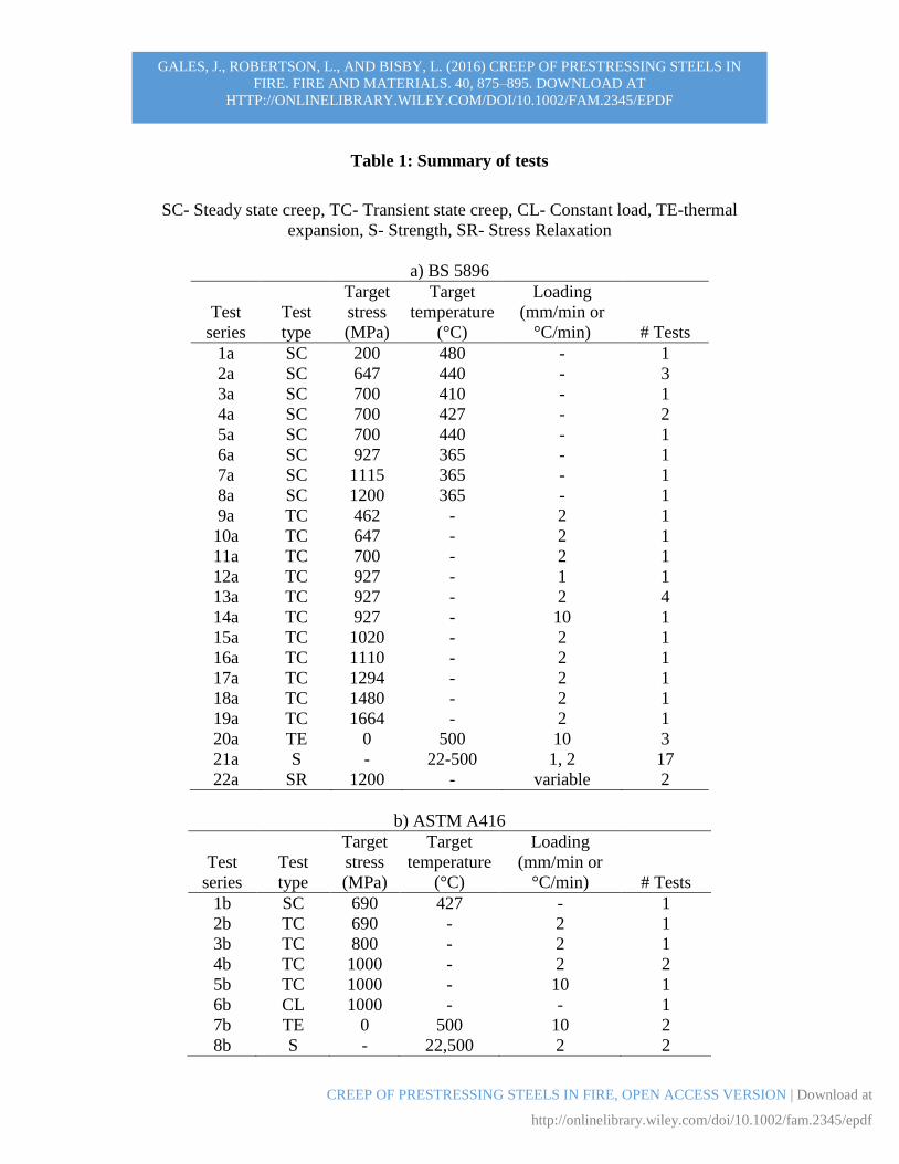
to estimate the creep strain. Table 1(a-c) provides an overview of the nearly 70 individual
tests that were performed, including: the type of test, heating rate, and loading rate.
GALES, J., ROBERTSON, L., AND BISBY, L. (2016) CREEP OF PRESTRESSING STEELS IN
FIRE. FIRE AND MATERIALS. 40, 875–895. DOWNLOAD AT
HTTP://ONLINELIBRARY.WILEY.COM/DOI/10.1002/FAM.2345/EPDF
CREEP OF PRESTRESSING STEELS IN FIRE, OPEN ACCESS VERSION | Download at
http://onlinelibrary.wiley.com/doi/10.1002/fam.2345/epdf
Validation of the experimental and DIC techniques for deformation measurement at high
temperature is given elsewhere [6].
3.4 Micro-structural analysis
For each prestressing steel type, unrestrained and unloaded wires were heated to
temperatures of 200, 400, 500, 600, 700 and 800ºC, respectively, using an annealing oven
a temperature ramp rate of 10°C/min. Four thermocouples were used to monitor the gas
and sample temperatures. The wires were held at the target temperature for 1.5 hours before
being cooled slowly in air. A small section was cut from each wire and mounted in
EpoxiCure resin. These were then ground using gradually finer grit paper and then polished
with diamond paste to obtain a flat, scratch-free surface. The samples were then etched
with 2% Nital solution to expose their grain structure. The microstructure of the samples
was examined using a Zeiss Axioscope light microscope following a procedure outlined in
Robertson et al. [7].
4. High temperature characterization for prestressing steel
Using the creep theory described above, DIC results are used in the following sections to
show high temperature creep deformation trends and material input parameters (Q, Z, cr,o)
for modelling modern (BS 5896) prestressing steel at high temperature. Other prestressing
steels are considered in Section 5.
4.1 Separating creep strain from total strain
A steady-state creep test may take days to complete under certain conditions, and because
creep can occur during loading, the true quantity of creep occurring in a test may be poorly
estimated [20][28]. In a transient creep test, mechanical strain can be approximately
quantified. Creep strain can be determined by subtracting strain from thermal expansion
and additional strains that occur with elastic modulus reductions at temperature increases.
However, as temperature increases the steel yield strength also decreases and becomes
intertwined with creep; this causes classical definitions of these distinct classes of strains
to lose their meaning [6].
In the current study, creep is approximated by the separation of thermal and
mechanical (elastic and plastic) strains. Thermal strains can be predicted by performing
transient heating tests under zero load. When comparing an unloaded thermal relaxation
test of BS 5896 prestressing steel against the predictions of EN 1992-1-2 [29] (Equation
4), a negligible (0.13%) strain difference was observed at 500ºC.
t = -2.01610-4 + 10-5 T + 0.410-8 T2 for 20ºC <T< 1200ºC [4]
It is therefore assumed herein that Equation 4 can be used to isolate creep strains. By
calculating the additional mechanical strain occurring due to elastic modulus reductions
during each measurement interval during heating, plastic strains can be approximately
determined. The EN 1992-1-2 [29] equations for elastic modulus reduction were utilized
to perform these adjustments in the current work. Whilst these equations presumably

GALES, J., ROBERTSON, L., AND BISBY, L. (2016) CREEP OF PRESTRESSING STEELS IN
FIRE. FIRE AND MATERIALS. 40, 875–895. DOWNLOAD AT
HTTP://ONLINELIBRARY.WILEY.COM/DOI/10.1002/FAM.2345/EPDF
CREEP OF PRESTRESSING STEELS IN FIRE, OPEN ACCESS VERSION | Download at
http://onlinelibrary.wiley.com/doi/10.1002/fam.2345/epdf
implicitly include some creep the EN 1992-1-2 [29] values were observed to correlate with
values observed in the mechanical testing described below.
4.2 Steady state and transient creep tests
Creep parameters can be extracted from the creep curves curve produced from creep tests,
as described earlier. Transient creep tests can better represent conditions during a real fire,
and given that these tests can be performed quickly, creep parameters for prestressing steel
at different stress levels can also be produced with fewer tests.
4.2.1 Activation energy for creep
To plot cr versus θ correctly, Q in Equation 3 must be determined. This requires careful
measurement of creep strains under various stress and temperature conditions. The
activation energy for creep, Q, is physically the energy needed to cause movement of atoms
(dislocation and/or slip of the grain structure) from one stable state to a new one. The value
of Q has real physical meaning, although it can easily be mistaken as simply an empirical
correction factor and this can produce erroneous cr versus θ plots that are fundamentally
flawed.
Four creep tests at steady state temperatures were performed at 410ºC, 427ºC
(repeated for verification), and 440ºC, all at a load equivalent to an initial stress of 700
MPa. Taking the minimum creep rate with respect to time and applying Equation 3 gives
Q as 37200K with correlation coefficient R2 = 1.00. This was verified by equating transient
tests (1ºC/min to 10ºC/min) with respect θ at 927 MPa.
Since Q depends on the microstructure of the steel it may also change with
temperature. The authors have found that within the tested stress and temperature ranges
used herein the derived creep parameters appear to be satisfactory (see Section 4.5).
Furthermore, since the available guidance typically restricts the stress ranges over which
prestressing steels can be used in service, only creep tests within this range (<500ºC and
<1300 MPa sustained stress) have previously been considered. The data set used to define
Q should be expanded to determine the sensitivity of the values extrapolated from the
available tests.
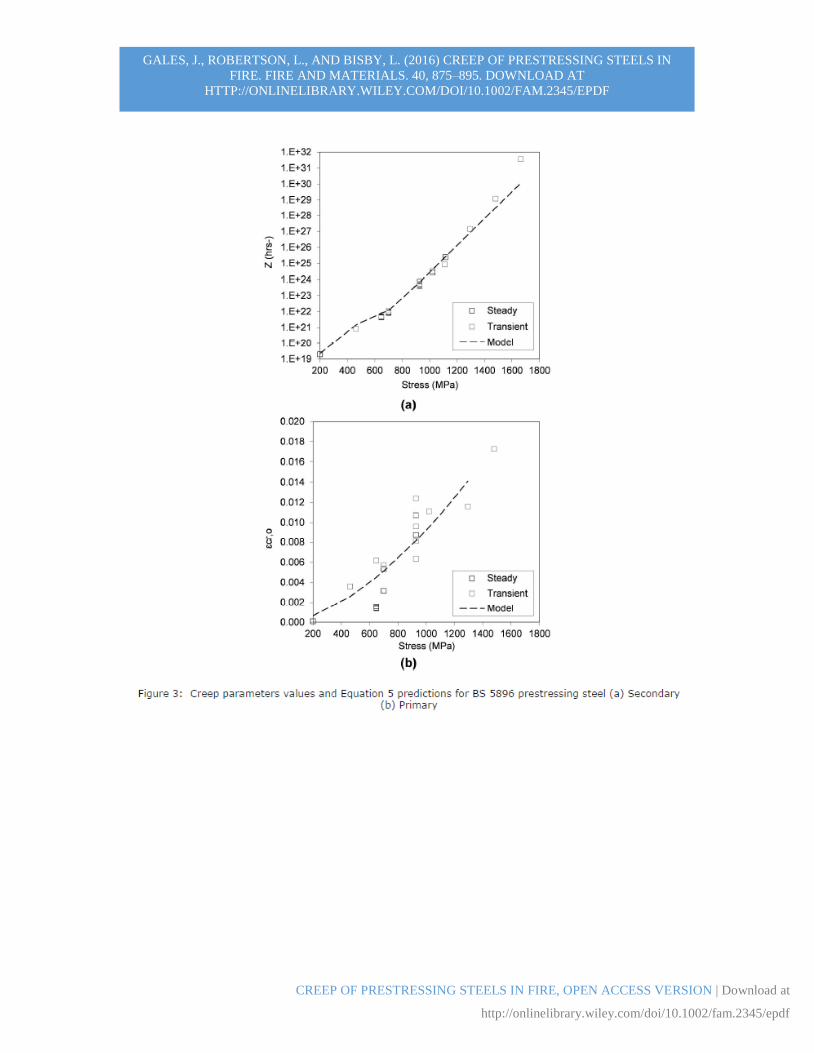
4.2.3 Creep parameters
Table 1(a) summarizes the test conditions used to characterize the BS 5896 prestressing
steel’s high temperature material response. Creep tests were performed at stress levels
between 200 MPa and 1664 MPa at temperatures below 500ºC. Expressions were then
developed to describe creep parameter variation with respect to applied stress, . The
resulting expressions for creep parameters for BS 5896 prestressing steel (for insertion into
the Harmathy [5] model) developed are:
687 MPa < σ < 1300 MPa [5a]
200 MPa < σ < 687 MPa [5b]
[5c]
019.0161002.1 exaeZ b 58107.0 xZ
645.17
0,10072.1 xc d
cr

GALES, J., ROBERTSON, L., AND BISBY, L. (2016) CREEP OF PRESTRESSING STEELS IN
FIRE. FIRE AND MATERIALS. 40, 875–895. DOWNLOAD AT
HTTP://ONLINELIBRARY.WILEY.COM/DOI/10.1002/FAM.2345/EPDF
CREEP OF PRESTRESSING STEELS IN FIRE, OPEN ACCESS VERSION | Download at
http://onlinelibrary.wiley.com/doi/10.1002/fam.2345/epdf
where the units of are MPa and Z are in hrs-1. Equations 5 (a-c) take the same form as
suggested by Harmathy and Stanzak [5] for Z, and cr,o, only with new values for empirical
constants a, b, c, and d. These coefficients were defined based on non-linear least-squares
empirical regressions. The equations above are strictly only valid with Q = 37200K and for
the stated stress ranges for this specific batch of prestressing steel. The Primary creep
variable was derived from poorly reproducible (however small) values. Both steady state
and transient tests were used to construct these equations. Figures 3(a) and 3(b) show the
raw data used to develop Equations 5a-c.
4.3 Tertiary creep behaviour
Equation 2 is traditionally assumed as being valid only to predict Primary and Secondary
creep; it was not developed for Tertiary creep, yet it assumes that knowledge of the creep
developed during the Secondary phase is sufficient to define failure [5][30]. Revisiting
Figure 1, which is based on a real creep test of prestressing steel but with magnitudes
removed for clarity of illustration, the cross-sectional area reduction due to necking during
Tertiary creep can be calculated a posteriori using DIC; the onset is taken herein as the
instant when necking appears within the DIC camera’s field of view. The reduction in
cross-sectional area for this figure was determined at the precise position of necking and at
another location arbitrarily chosen away from the position of necking.
Figure 1 shows the creep curve (cr versus θ) and cross-sectional area reduction at
these two locations for a typical test. Gales et al. [6] previously hypothesized that Tertiary
creep depends on both reductions in material properties and changes in the geometry; this
simply being the engineering strain manifestation of necking. In the current study the
authors hypothesize, using the measured reduced cross-sectional area, that Equation 2 can
be compensated to account for the measured area reduction; and therefore to compensate
for the true stress (provided this changes sufficiently slowly). Two creep tests on BS 5896
steel are used to illustrate this idea. The first is a steady state test performed at 647 MPa
initial stress and 440ºC. Equation 2 was extrapolated with the appropriate Z, and cr,o values
(which would be applicable for true stress). Figure 4 shows the predicted true stress
compensated creep curve, as well as the prediction without compensation. It is clear that
Equation 2 is able to closely predict creep strains provided that the true stress is estimated
correctly based on the necking area a posteriori. A second, more complicated transient test
can also be considered and is also shown in Figure 4. In this case thermal dilation effects
are present which must also be separated. Figure 4 shows the predicted responses; again
the model matches the trends, however with obvious scatter most likely due to the
sensitivity associated with measuring such small displacement and/or the rapid changes in
area (and hence true stress).
Two additional plots are also shown which help to validate this hypothesis while
also demonstrating good repeatability between tests. Figure 5 shows predictions and results
for two transient creep tests at 927 MPa with the compensated model prediction shown.
Figure 6 shows two steady state tests at 647 MPa. All predictions compare well, with
similar error as in Figure 4 (<15% difference between modelled and experimental strain)
and considerable improvements in the accuracy compared to the model without area
GALES, J., ROBERTSON, L., AND BISBY, L. (2016) CREEP OF PRESTRESSING STEELS IN
FIRE. FIRE AND MATERIALS. 40, 875–895. DOWNLOAD AT
HTTP://ONLINELIBRARY.WILEY.COM/DOI/10.1002/FAM.2345/EPDF
CREEP OF PRESTRESSING STEELS IN FIRE, OPEN ACCESS VERSION | Download at
http://onlinelibrary.wiley.com/doi/10.1002/fam.2345/epdf
reduction. These data support the hypothesis that the Harmathy model can be extended for
use in the tertiary creep phase, albeit only once the area reduction is known.
The above suggests a need to perform additional research to study Tertiary creep
and to define an a priori Tertiary creep model without the need to measure the necking
before Tertiary creep can be predicted; this is an ultimate goal for failure analysis of UPT
concrete structures in fire. The following issues also need to be addressed in future
research:
By considering the point at which specimens ‘neck’ in the Tertiary phase and the strains
in this region, it appears possible to model Tertiary creep. However, if specimen area
is taken away from the necking region and used to quantify true stress the model is
unable to predict the Tertiary creep deformation. This suggests that any accurate model
for Tertiary creep must consider volumetric changes near failure.
A more thorough investigation into the sensitivity of the creep equations in modelling
Tertiary creep is needed since stresses increase exponentially during this phase. The
creep model was only intended for use when true stress changes relatively slowly.
The volumetric changes observed during Tertiary creep require better understanding.
On the macro-scale Tertiary creep can be distinguished by physically observing
localized necking. On the micro-scale it is evident that micro-cavities and void
formations play roles.
4.4 Mechanical Behaviour To provide some insight into failure, mechanical tests to failure were performed at various
steady-state temperatures. The strength relationship with temperature obtained for the BS
5896 steel is shown in Figure 7 (loading rate of 2 mm/min). An average ultimate strength
(fpu) at ambient temperature of 2033 ± 11 MPa was obtained, with strength reductions
observed at 100ºC intervals up to 500ºC. Temperatures greater than 500ºC were not
considered, since prestressing steel would rarely be relied on at such high temperatures in
design. High temperature strength tests were repeated twice, showing good repeatability.
The true stresses shown in the figures are based on DIC measurements of reduced cross-
sectional areas. It is clear that true stress increases drastically approaching failure, in much
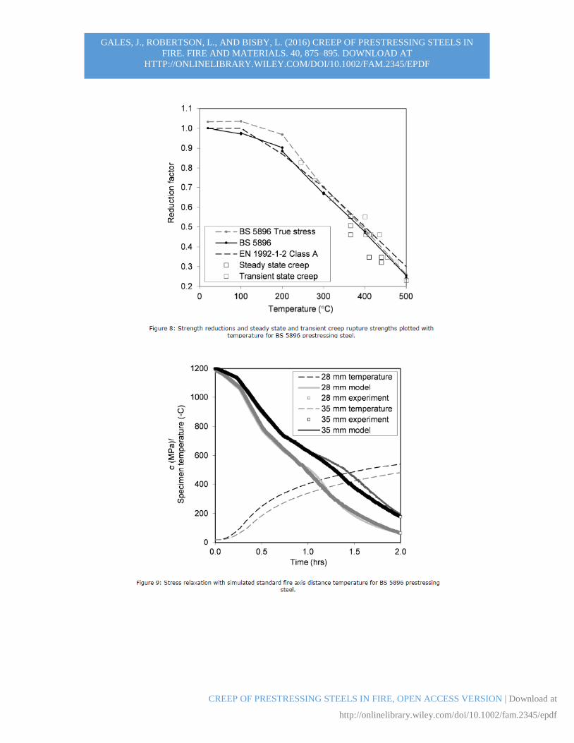
the same way as during Tertiary creep. Figure 8 shows the observed strength reductions
along with those suggested in EN 1992-1-2 [29]. These are based on engineering stress
rather than true stress. Nonetheless, Figure 8 shows that the strength reduction of the BS
5896 steel follows the expected behaviour, with nearly 50% tensile stress loss at
temperatures below 400ºC.
Design code guidance rarely states the rates used in tests (loading or heating rates)
to develop high temperature material property reduction factors. These rates can, however,
be expected to influence the results obtained since failure is inevitably influenced to more
or lesser degree by time-dependent creep. In the steady-state strength tests undertaken for
the current project, a crosshead speed of 2 mm/min was chosen. Had a different
displacement rate been used, say 1 mm/min, the high temperature fpu values would have
been different, resulting in different reduction factors (this was seen when a second 500ºC
test was performed at 1 mm/min and the corresponding high temperature fpu was 12% lower

GALES, J., ROBERTSON, L., AND BISBY, L. (2016) CREEP OF PRESTRESSING STEELS IN
FIRE. FIRE AND MATERIALS. 40, 875–895. DOWNLOAD AT
HTTP://ONLINELIBRARY.WILEY.COM/DOI/10.1002/FAM.2345/EPDF
CREEP OF PRESTRESSING STEELS IN FIRE, OPEN ACCESS VERSION | Download at
http://onlinelibrary.wiley.com/doi/10.1002/fam.2345/epdf
than in tests performed at 2 mm/min). Loading and heating rates should therefore be
reported when high temperature tensile test results presented.
Two additional observations are noteworthy in Figure 8: first, the predominant
heating rate used for transient creep tests (2ºC/min) appears to agree well with material
property reduction factors given in [29], as does the displacement rate of 2 mm/min; and
second, depending on the time of heating and load scenario it is possible to fail the
prestressing steel below the EN 1992-1-2 temperature definition of failure. Additional
research into failure of prestressing steel at high temperature is warranted so that Tertiary
creep and mechanical failures can be accurately distinguished and predicted.
4.5 Validation
A validation exercise was performed to confirm that the BS 5896 prestressing steel creep
parameters developed herein could be satisfactorily used to predict Primary and Secondary
creep response. The new parameters given in Equation 5 were used in conjunction with the
stress relaxation computational code described by Gales et al. [4], which also uses Equation
2 for predicting and modelling creep.
The aforementioned Instron 600LX testing frame and environmental chamber were
used to conduct two stress relaxation tests of BS 5896 prestressing steel to provide raw data
for modelling purposes. Using the heat transfer model described in Bisby and Kodur [32],
the environmental chamber was programmed to simulate the heating exposure for
prestressing steel embedded in a semi-infinite concrete slab and exposed to an ASTM E119
standard fire from below [33]. Two transient heating scenarios were used, representing
predicted heat transfer behaviour for prestressing steel at two concrete cover axis distances,
namely 28 mm and 35 mm. These axis distances represent typical covers required to
achieve fire resistance ratings of 120 minutes in the International Building Code [34] and
EN 1992-1-2 [29], respectively, for ‘continuous’ construction. Five thermocouples (TCs)
were used to characterize the longitudinal profile of temperature of the prestressing steel
for modelling purposes. One TC was placed on the bottom on the environmental chamber
on the prestressing steel, three TCs were equally placed inside the chamber on the
prestressing steel, and one TC was placed on the prestressing steel just outside the top port
of the chamber. The test began at an initial stress level of 1200 MPa (as might be typical
for UPT prestressing steel in a building in practice). The grips were locked in place and the
steel was allowed to relax by thermal deformation and creep.
Figure 9 illustrates the stress relaxation from both tests, along with the predictions
using the computational code [4]; the peak temperature of the prestressing steel is also
given. Less than 50 MPa difference between the predictions and the tests was observed,
thus verifying the new creep parameters.
5. Creep response In practice, the available creep parameters for prestressing steel are widely assumed to
apply to all grades sourced from internationally. However, manufacturing and
microstructural differences may influence creep deformations at high temperature. This
section compares the creep response of “equivalent” grades of prestressing steel sourced
from different locations internationally.
GALES, J., ROBERTSON, L., AND BISBY, L. (2016) CREEP OF PRESTRESSING STEELS IN
FIRE. FIRE AND MATERIALS. 40, 875–895. DOWNLOAD AT
HTTP://ONLINELIBRARY.WILEY.COM/DOI/10.1002/FAM.2345/EPDF
CREEP OF PRESTRESSING STEELS IN FIRE, OPEN ACCESS VERSION | Download at
http://onlinelibrary.wiley.com/doi/10.1002/fam.2345/epdf
5.1 Creep parameters for other prestressing steels
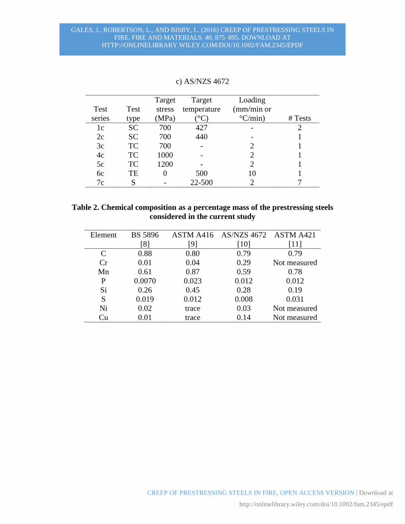
Table 1 describes the tests performed for each of the prestressing steels. Where possible
the testing regime was the same as for the BS 5896 prestressing steel discussed above, and
the general observations already made regarding repeatability, steady state versus transient
testing equivalence, and increases in Z with increases in load level all hold equally.
However, the activation energies for creep, Q, for each specific prestressing steel were
considerably different. As the supply of each specific steel was limited, Q for the ASTM
A416 steel was approximated in this study as 23000K based on equating two transient
creep tests at the same load level but different heating rate. The AS/NZS 4672 steel Q value
was derived from Equation 3 using steady state tests, giving Q = 34350K. Equations 6 and
7 were derived based on an R2 > 0.99 fit with respect to minimum creep rate, Z. These
equations should only be used with the activation energies noted above.
NZS 4672 prestressing steel
700 MPa < σ < 1200 MPa [6a]
[6b]
ASTM A416 prestressing steel
690 MPa < σ < 1000 MPa [7a]
[7b]
The previous equations derived by Harmathy [5], with an activation energy of 30550K for
ASTM A421 [11] prestressing steel are:
172 < σ < 690 MPa [8a]
[8b]
Equations 6 through 8 clearly show that each of these nominally identical prestressing
steels has considerably different derived creep parameters.
5.2 Prestressing steel comparison
Three additional test series were undertaken to more thoroughly compare the different
prestressing steels:
(1) Comparative creep tests – a creep test was performed for each steel at 427ºC at
approximately 35% of the ambient fpu. This allowed the creep response of all three
modern prestressing steel to be compared experimentally for a single, representative
load case. Strength tests were also performed for the AS/NZS 4672 steel for
comparison with the BS 5896 steel, considering both strength and elastic modulus.
(2) Microstructural analysis – all three steels were compared at the microstructural level
(at 100X magnification). Grain structures at ambient and after exposure to steady state
heating were compared for each.
(3) Numerical comparisons – a numerical modelling exercise was performed to construct
predicted creep response curves for each of the steels for a simulated creep test using
015.0141037.4 exaeZ b 72.211
0,1015.1 xc d
cr
0145.08105.2 exaeZ b 2.17
0,101.4 xc d
cr
0145.0131021.8 exaeZ b 67.05
0,1026.9 xc d
cr

GALES, J., ROBERTSON, L., AND BISBY, L. (2016) CREEP OF PRESTRESSING STEELS IN
FIRE. FIRE AND MATERIALS. 40, 875–895. DOWNLOAD AT
HTTP://ONLINELIBRARY.WILEY.COM/DOI/10.1002/FAM.2345/EPDF
CREEP OF PRESTRESSING STEELS IN FIRE, OPEN ACCESS VERSION | Download at
http://onlinelibrary.wiley.com/doi/10.1002/fam.2345/epdf
specific creep parameters in comparison to those proposed by Harmathy and Stanzak
[5] or currently suggested in the literature [20].
5.2.1 Comparative creep tests
Steady state creep tests were conducted at 427ºC (chosen as the assumed critical
temperature [34]) at an approximate initial stress (constant load) of 35% of fpu (about
700MPa). Repeat test were also performed for BS 5896 and AS/NZS 4672 steels. It was
not possible to perform a repeat test for the ASTM A416 steel due to a limited of supply of
this material. The full creep curves (Figure 10) and the normalized creep rates were
compared (Figure 11).
Figure 10 gives the strain versus time results for one creep test for each steel, and
shows that the AS/NZS steel exhibited the least creep, whereas the BS 5896 steel exhibited
the most. This confirms that nominally identical steels may display significantly different
creep behaviour, and that this must be accounted for in analyses where creep plays an
important role (as in tendon rupture predictive modelling).
Figure 11 illustrates the normalized time (the total test time divided by its duration)
with respect to creep rate (with the creep rate determined with respect to each 10%
normalized time interval) for both the BS 5896 and AS/NZS 4672 steels; repeat tests are
included. The AS/NZS steel exhibited a lower creep rate than BS 5896 steel. Both AS/NZS
steel tests lasted for more than 5 hours before failure, whereas the BS 5896 steel tests lasted
less than 1.2 hours until failure and the ASTM A416 lasted 1.4 hours. The AS/NZS steel
thus exhibits higher creep resistance (about 4 times in terms of duration at this load and
temperature) than ‘equivalent’ steels from elsewhere. The current comparison and results
are only for a single stress level; additional research in this area is warranted.
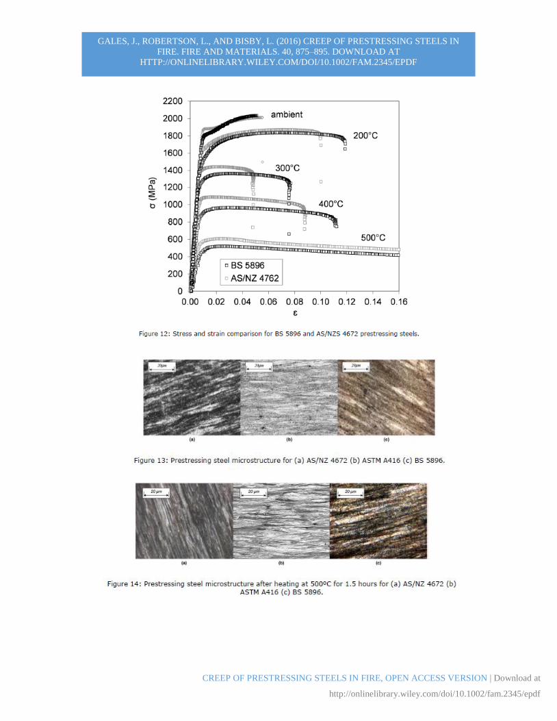
Figure 12 shows a comparison of the strength of BS 5896 and AS/NZS 4672 steels.
Despite yielding equivalent performance at ambient temperature, as expected, the AS/NZS
4672 steel shows obviously greater strength at elevated temperature when compared to the
BS 5896 steel. At 400ºC the BS 5896 steel has an ultimate strength of 965 MPa, whereas
the AS/NZS 4672 specimen has a strength of 1079 MPa. The AS/NZS 4672 steel also
shows lower ultimate strain at higher temperatures in comparison to BS 5896. AS/NZS
4672 showed similar retained elastic modulus as BS 5896.
The high temperature performance of the prestressing steels may be partly
explained by their histories of manufacture, specific alloying, and chemical composition.
Table 2 shows the composition of the prestressing steels used in this study, demonstrating
clear differences in material composition between the steels. Mill certificates for each steel
indicated the proportions of only Carbon, Manganese, Phosphorous, Silicon and Sulphur,
with each being reasonably similar on this basis. Table 2 shows that the steels are subtly
different. For example, the addition of higher chromium and lower sulphur content in the
AS/NZS steel, which was manufactured using an electric arc furnace. Chromium is
typically alloyed to improve resistance to corrosion, but is also known to improve retention
of mechanical properties at high temperature [35]; this improvement for prestressing steel
behaviour in fire with additional chromium has not previously been studied to the
knowledge of the authors. The specimens with higher sulphur contents suggest blast
furnace manufacturing. Since all prestressing steels tested herein were sourced from
GALES, J., ROBERTSON, L., AND BISBY, L. (2016) CREEP OF PRESTRESSING STEELS IN
FIRE. FIRE AND MATERIALS. 40, 875–895. DOWNLOAD AT
HTTP://ONLINELIBRARY.WILEY.COM/DOI/10.1002/FAM.2345/EPDF
CREEP OF PRESTRESSING STEELS IN FIRE, OPEN ACCESS VERSION | Download at
http://onlinelibrary.wiley.com/doi/10.1002/fam.2345/epdf
different mills and fabricated in different countries, since the manufacture of prestressing
steel is known to affect the creep response at ambient temperature [36], and since creep
accelerates at elevated temperature, the manufacturing and alloying history can at least
partly explain the different high temperature creep responses. Differences in AZS/NZ 4672
steel led to a strength increase at high temperature of at least 10% for every temperature
considered, and to a four fold increase in creep times observed at temperatures considered
critical (427°C) in fire under realistic stress levels (700MPa). It is therefore clear that the
creep performance of prestressing steel in fire can neither be assumed on the basis of the
available creep parameters, nor on the basis of mill certificates alone.
5.2.2 Microstructural analysis
The microstructural characteristics of the AS/NZS 4672 and BS 5896 steels before and
after high temperature exposure were considered. Additional micro-structural analysis of
prestressing steel wires (ASTM A416 steel) was previously undertaken by MacLean
[37][38] and is included for comparison. The Micro-structural analysis is of particular
importance with respect to the stability of the prestressing steel’s microstructure – an
assumption that could lend credence to the use of a constant Q for the transient temperature
ranges used in this paper.
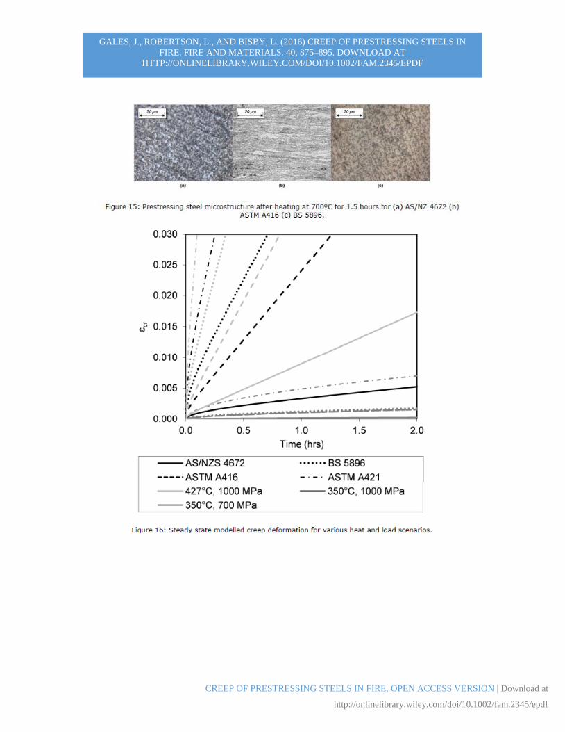
Figures 13 to 15 show micro-structural images for wires at ambient temperature
and after exposure to 500ºC and 700ºC, respectively, for longitudinal sections. Sections
from both unheated prestressing wires and those heated below 500ºC exhibited long, well
defined grains running parallel across the field of view. These grains are a result of the cold
drawing manufacturing process. Pearlitic banding is also evident. This pearlitic banding
disappears after exposure to temperatures above 500ºC. Steel heated to 500°C and 600°C
exhibited a finer grain structure, having less well-defined longitudinal grains. Pearlitic
bands began to dissociate into ferrite and globular iron carbide. By 700ºC the directionality
of the grain structure is lost. Each prestressing steel wire exhibited similar trends at each
temperature. Each structure appeared micro-structurally stable below temperatures of
500ºC. This supports use of the creep parameters applied in the current study, since all
testing was performed below 500ºC. Above 500ºC microstructure changes can be expected
and parameters (such as Q) may be influenced, thus affecting the validity of the creep
theory presented herein.
5.2.3 Predictive numerical modelling
Two numerical modelling predictions were made to compare modern and older creep
parameters (for Primary and Secondary creep only) using equations 1 and 2. This
illustrative comparison is intended to show that the creep model developed for each
prestressing steel predict different levels of creep behaviour under the same loading and
heating conditions. The modelling results are a compilation of preceding creep parameter
equations (equations 6 to 8) used in conjunction with Equation 2. A first comparison
(Figure 16) considers a steady state temperature of 350ºC and loads of 700 and 1000 MPa.
A second comparison (also shown in Figure 16) considers loading of 700 MPa and two
steady state temperatures of 350ºC and 427ºC. In both comparisons, the predictions suggest
that the older prestressing steel would experience the highest creep losses, whereas the
GALES, J., ROBERTSON, L., AND BISBY, L. (2016) CREEP OF PRESTRESSING STEELS IN
FIRE. FIRE AND MATERIALS. 40, 875–895. DOWNLOAD AT
HTTP://ONLINELIBRARY.WILEY.COM/DOI/10.1002/FAM.2345/EPDF
CREEP OF PRESTRESSING STEELS IN FIRE, OPEN ACCESS VERSION | Download at
http://onlinelibrary.wiley.com/doi/10.1002/fam.2345/epdf
AS/NZS steel would exhibit the lowest. This again emphasizes that creep parameters
should strictly only be used with the steel for which they were developed.
6 Recommendations
There are two main reasons that a designer may need to estimate creep of a prestressing
steel at elevated temperatures: (1) to evaluate the potential for prestress relaxation and the
possible consequences for overall structural performance – where maximum tendon stress
losses are desired, and (2) to conservatively predict prestressing steel rupture – where
minimum tendon stress losses are desired. In the event that an estimate of stress relaxation
of prestressing steel is needed to consider fire-degraded shear and flexural capacities of a
UPT concrete slab (which rely on the in-service stress level for capacity estimation), the
creep parameters derived for the BS 5896 prestressing steel could be considered. These
parameters can be used for the full service stress range, and will predict more conservative
relaxation than the parameters derived for other modern prestressing steels in the event that
the prestressing tendons do not rupture during fire. However, if a designer needs to predict
the earliest stress-strength interception (in the absence of more research into Tertiary creep
and mechanical failure) to predict premature tendon rupture, the AS/NZS parameters could
be considered since they will yield a conservative prediction.
In the absence of a statistical study of multiple mill prestressing steels analyzed for
high temperature performance, the authors recommend that designers requiring accurate
creep information should develop their own high temperature creep parameters for specific
prestressing steels. A reasonably limited suite of creep tests may be used to determine new
material input parameters. The minimum number of necessary tests, based on the work
presented in the current paper, is five. These tests would include two steady state creep
tests at the same stress level, but different temperature, and would be used to derive Q,
which can be used to relate time and temperature effects. The chosen stress level should be
between the upper stress level in the expected in-service stress (i.e., about 1200 MPa) and
a lower stress level that the designer would tolerate in the event of high temperature
exposure. This lower bound value may represent the stress loss needed to cause a flexural
or shear failure of the element. The temperatures of these tests must also adhere to three
additional criteria: (1) they should be below 500ºC for prestressing steel; (2) two different
temperatures should be chosen; and (3) the temperatures in conjunction with the stress level
should not cause mechanical yielding before the constant load level is reached. The last
point is necessary to produce θ-εcr creep curves with minimal influences from mechanical
damage at the beginning of the test. EN 1992-1-2 [29] could be used in the absence of new
tensile strength tests. A minimum of three transient tests at different service stress levels
(within the aforementioned stress range), including one stress level equal to one of the two
steady state tests noted above are also needed. It would be preferable to conduct as many
transient tests as possible, at different loads, to accurately characterise the behaviour of the
steel at all relevant stress levels. A repeat transient test at the same sustained stress level as
the steady state test could also be performed to verify the activation energy.
7 Conclusions

GALES, J., ROBERTSON, L., AND BISBY, L. (2016) CREEP OF PRESTRESSING STEELS IN
FIRE. FIRE AND MATERIALS. 40, 875–895. DOWNLOAD AT
HTTP://ONLINELIBRARY.WILEY.COM/DOI/10.1002/FAM.2345/EPDF
CREEP OF PRESTRESSING STEELS IN FIRE, OPEN ACCESS VERSION | Download at
http://onlinelibrary.wiley.com/doi/10.1002/fam.2345/epdf
This research presented herein has provided a number of novel insights and
recommendations regarding creep in prestressing steel. These are summarized as follows:
High temperature Primary and Secondary creep parameters have been developed and
validated and can be used to model creep deformation of a specific BS 5896
prestressing steel over the full credible in-service stress range.
Microscopic study of the three prestressing steels tested herein indicated no observable
microstructural changes with increasing temperature below 500oC. This supports use
of transient creep tests as a means of deriving creep parameters for prestressing steels
and the use of creep models under transient temperature regimes.
Chemical analysis of the three prestressing steels indicated distinct manufacturing
differences for seemingly equivalent prestressing steels that clearly affect high
temperature creep and strength behaviour. Current guidance fails to highlight
variability between different steels despite the influence on high temperature
behaviour.
Guidance has been given for development of case-specific creep parameters other than
those already available. This allows for relatively rapid and economic development of
creep parameters with a minimum suite of five creep tests.
Valuable material behaviour information has been provided that can be used to build
validated numerical models of structural fire experiments on prestressed and post-
tensioned concrete structural elements, and to develop defensible structural fire models;
these are essential to advance towards performance based structural fire engineering
design.
Results showed that existing creep models can be compensated to consider the
‘volumetric’ changes associated with Tertiary creep behaviour. However additional
research is needed to model Tertiary creep a priori. Accurate modelling of Tertiary
creep requires the underlying mechanisms causing necking behaviour of the specimen
at high temperature to be better understood. It has been demonstrated that optical strain
measurement can be used to provide the requisite data for this work.
Despite all prestressing steel specimens having essentially equivalent mechanical
characteristics at ambient temperature, their behaviour at high temperature differed
considerably. Where consideration of creep is known to be important for predicting
structural response (and failure), creep parameters should therefore strictly only be used
with the specific prestressing steel for which they were developed.
Acknowledgements
The authors would like to acknowledge the contributions of Dr Andy Take, Zuzana
Dudorova, Dr Jane Blackford, Kevin MacLean, Ryan Haick, and Dr Andrew Buchanan.
We gratefully acknowledge the support of the Ove Arup Foundation, the UK Royal
Academy of Engineering, the Natural Sciences and Engineering Research Council of
Canada, and Bridon Steel.
References
GALES, J., ROBERTSON, L., AND BISBY, L. (2016) CREEP OF PRESTRESSING STEELS IN
FIRE. FIRE AND MATERIALS. 40, 875–895. DOWNLOAD AT
HTTP://ONLINELIBRARY.WILEY.COM/DOI/10.1002/FAM.2345/EPDF
CREEP OF PRESTRESSING STEELS IN FIRE, OPEN ACCESS VERSION | Download at
http://onlinelibrary.wiley.com/doi/10.1002/fam.2345/epdf
[1] Gales, J., Bisby, L., and Gillie, M. Unbonded Post Tensioned Concrete in Fire: A
Review of Data from Furnace Tests and Real Fires. Fire Safety Journal. 2011; 46
(4):151-163.
[2] Gales, J., Bisby, L., and Gillie, M. Unbonded Post Tensioned Concrete Slabs in Fire –
Part I – Experimental Response of Unbonded Tendons under Transient Localized
Heating. Journal of Structural Fire Engineering.2011; 2 (3):139-154.
[3] Gales, J., Bisby, L., and Gillie, M. Unbonded Post Tensioned Concrete Slabs in Fire –
Part II – Modelling Tendon Response and the Consequences of Localized Heating.
Journal of Structural Fire Engineering. 2011; 2(3):155-172.
[4] Gales, J., Bisby, L., MacDougall, C., and MacLean, K. Transient High-Temperature
Stress Relaxation of Prestressing Tendons in Unbonded Construction. Fire Safety Journal,
2009; 44, 570-579.
[5] Harmathy, TZ., and Stanzak, W. Elevated-Temperature Tensile and Creep Properties
of Some Structural and Prestressing Steels. Fire Test Performance ASTM Special Technical
Publication 464, ASTM, Philadelphia Pa, 1970. 186-207.
[6] Gales, J., Bisby, L., and Stratford, T. New Parameters to Describe High Temperature
Deformation of Prestressing Steel Determined using Digital Image Correlation.
Structural Engineering International. 2012; 22(4): 476-486.
[7] Roberston, L., Dudorova, Z., Gales, J., Vega, E., Stratford, T., Smith, H., Blackford, J.,
and Bisby, L. Micro-structural and Mechanical Characterization of Post-tensioning
Tendons Following Elevated Temperature Exposure. Applications of Structural
Engineering Conference, Prague, CZ, 2013; 474-479.
[8] BSi. Specification for High Tensile Steel Wire and Strands for the Prestressing of
Concrete, BS 5896-12. 2012. British Standards Institution, London.
[9] ASTM A416. Standard Specification for Steel Strand, Uncoated Seven-Wire for
Prestressed Concrete. Rep. No. A416 / A416M-01, American Society for Testing and
Materials, West Conshohocken, PA. 2003.
[10] AS/NZS 4672. Prestressing Strand Standard 4672. Standards Australia New Zealand,
Wellington, NZ. 2007.
[11] ASTM A421. Standard Specification for Uncoated Stress- Relieved Steel Wire for
Prestressed Concrete. Rep. No. A421 / A421M-01, American Society for Testing and
Materials, West Conshohocken, PA. 1965.
[12] Harmathy, TZ., and Lie, TT. Fire Test Standard in the Light of Fire Research. ASTM
STP 464, 85-97.
[13] Bisby, L., Mostafaei, H., Pimienta, P. State of the Art on Fire Resistance of Concrete
Structures: Structure-Fire Model Validation. In NIST-Special Publications: International
R&D Road Map for Fire Resistance of Structures. 2014. 26pp. In press.
GALES, J., ROBERTSON, L., AND BISBY, L. (2016) CREEP OF PRESTRESSING STEELS IN
FIRE. FIRE AND MATERIALS. 40, 875–895. DOWNLOAD AT
HTTP://ONLINELIBRARY.WILEY.COM/DOI/10.1002/FAM.2345/EPDF
CREEP OF PRESTRESSING STEELS IN FIRE, OPEN ACCESS VERSION | Download at
http://onlinelibrary.wiley.com/doi/10.1002/fam.2345/epdf
[14] Gales, J., Bisby, L., Stratford, T., Krajcovic, M. Tests of continuous post-tensioned
concrete slabs under localized fires. Interflam 2013:13th International Conference and
Exhibition on Fire Science and Engineering. Royal Holloway College. 1131-1142.
[15] Gales, J., Bisby L. Deformation and response of continuous and restrained post-
tensioned concrete slabs at high temperatures. Proceedings of the 8th International
Conference on Structures in Fire. Shanghai, China. 305-312.
[16] Gales, J. Unbonded Post-tensioned Concrete Structures in Fire. PhD thesis. University
of Edinburgh. 2013. 348pp.
[17] Bailey, CG., and Ellobody, E. Comparison of Unbonded and Bonded Post-Tensioned
Concrete Slabs under Fire Conditions. The Structural Engineer. October 2009; 87 (19), 23-
31.
[18] Bailey, CG., and Ellobody, E. Fire Tests on Unbonded Post-Tensioned One-way
Concrete Slabs. Magazine of Concrete Research. 2009; 61 (1), 67-76.
[19] Harmathy, TZ. Comprehensive Creep Model. Transactions of the ASME Journal of
Basic Engineering, 1967; 89(3): 496-502.
[20] Purkiss, JA., and Li, Y. Fire Safety Engineering Design of Structures. BH, London,
UK. 2013.
[21] Yao, H., Xuan, F., Wang, Z., and Tu, S. A Review of Creep Analysis and Design
under Multi-axial Stress States. Nuclear Engineering and Design, 2007; 237, 1969-1986.
[22] Smith, W. Principals of Material Science and Engineering. McGraw Hill, NY. 1996.
[23] Williams, SJ., Bache, MR., and Wilshire, B. Recent Developments in Analysis of High
Temperature Creep and Creep Fracture Behaviour. Materials Science and technology.
2010; 26 (11), 1332-1337.
[24] Zener, C., and Hollomon J. Effect of Strain Rate upon Plastic Flow of Steel. Journal
of Applied Physics, 1944; 15-22.
[25] Harmathy, T.Z. Properties of Building Materials. The SFPE Handbook of Fire
Protection Engineering. 1988; 378-391.
[26] Lewinsohn, CA., Bakis, CE., Tressler, RE. Methods of Determining the Temperature
Dependence of Primary Creep. Fiber, Matrix, and Interface properties ASTM STP 1290,
1996; 9-18.
[27] White, DJ., Take, WA., Bolton, MD. Soil Deformation Measurement Using Particle
Image Velocimetry (PIV) and Photogrammetry. Geotechnique. 2003; 53(7), 619-631.
[28] Holdsworth, S. Advances in Assessment of Creep Data during the Past 100 years.
Transactions of the Indian Institute of Metals. 2010; 63 (2-3), 93-99.
[29] CEN. Eurocode 2: Design of Concrete Structures, Parts 1-2: General rules-Structural
fire design, EN 1992-1-2. European Committee for standardization, Brussels. 2004.
GALES, J., ROBERTSON, L., AND BISBY, L. (2016) CREEP OF PRESTRESSING STEELS IN
FIRE. FIRE AND MATERIALS. 40, 875–895. DOWNLOAD AT
HTTP://ONLINELIBRARY.WILEY.COM/DOI/10.1002/FAM.2345/EPDF
CREEP OF PRESTRESSING STEELS IN FIRE, OPEN ACCESS VERSION | Download at
http://onlinelibrary.wiley.com/doi/10.1002/fam.2345/epdf
[30] Williams-Leir, G. Creep of Structural Steel in Fire: Analytical Expressions. Fire and
Materials. 1983; 7(2), 73-78.
[31] Gales, J. Transient High-temperature Prestress Relaxation of Unbonded Prestressing
Tendons for Use in Concrete Slabs. M.Sc. Thesis, Department of Civil Engineering,
Queen’s University, Kingston, On, Canada. 2009; 197 pp.
[32] Bisby, L., and Kodur, V. Evaluation of Fire Endurance of Concrete Slabs Reinforced
with Fiber Reinforced Polymer Bars. ASCE Journal of Structural Engineering. 2005;
131(1), 34-43.
[33] ASTM E119. Test Method E119-12: Standard Methods of Fire Test of Building
Construction and Materials” Rep. No. E119-12, American Society for Testing and
Materials, West Conshohocken, PA 2012.
[34] IBC. International Building Code. International Code Council, USA. 2012.
[35] Malouk, M, and Zaniewski Z. Materials for Civil and Construction Engineers. 3rd
edition, Pearson, 2011; 582 pp.
[36] Clark, N., and Walley, T. Creep of High Tensile Steel Wire. ICE Proceedings. 1953;
2(2). 107-154.
[37] MacLean K. Post-fire Assessment of Unbonded Post-tensioned Concrete slabs: Strand
Deterioration and Prestress Loss. M.Sc Thesis, Department of Civil Engineering, Queen’s
University, Kingston, ON, Canada. 2007.
[38] MacLean, K., Bisby, LA., and MacDougall, CC. Post-fire Assessment of Unbonded
Post-tensioned Slabs: Strand Deterioration and Prestress Loss. ACI-SP 255: Designing
Concrete Structures for Fire Safety, American Concrete Institute, 2008; 10 pp.
GALES, J., ROBERTSON, L., AND BISBY, L. (2016) CREEP OF PRESTRESSING STEELS IN
FIRE. FIRE AND MATERIALS. 40, 875–895. DOWNLOAD AT
HTTP://ONLINELIBRARY.WILEY.COM/DOI/10.1002/FAM.2345/EPDF
CREEP OF PRESTRESSING STEELS IN FIRE, OPEN ACCESS VERSION | Download at
http://onlinelibrary.wiley.com/doi/10.1002/fam.2345/epdf
Table 1: Summary of tests
SC- Steady state creep, TC- Transient state creep, CL- Constant load, TE-thermal
expansion, S- Strength, SR- Stress Relaxation
a) BS 5896
Test
series
Test
type
Target
stress
(MPa)
Target
temperature
(°C)
Loading
(mm/min or
°C/min) # Tests
1a SC 200 480 - 1
2a SC 647 440 - 3
3a SC 700 410 - 1
4a SC 700 427 - 2
5a SC 700 440 - 1
6a SC 927 365 - 1
7a SC 1115 365 - 1
8a SC 1200 365 - 1
9a TC 462 - 2 1
10a TC 647 - 2 1
11a TC 700 - 2 1
12a TC 927 - 1 1
13a TC 927 - 2 4
14a TC 927 - 10 1
15a TC 1020 - 2 1
16a TC 1110 - 2 1
17a TC 1294 - 2 1
18a TC 1480 - 2 1
19a TC 1664 - 2 1
20a TE 0 500 10 3
21a S - 22-500 1, 2 17
22a SR 1200 - variable 2
b) ASTM A416
Test
series
Test
type
Target
stress
(MPa)
Target
temperature
(°C)
Loading
(mm/min or
°C/min) # Tests
1b SC 690 427 - 1
2b TC 690 - 2 1
3b TC 800 - 2 1
4b TC 1000 - 2 2
5b TC 1000 - 10 1
6b CL 1000 - - 1
7b TE 0 500 10 2
8b S - 22,500 2 2
GALES, J., ROBERTSON, L., AND BISBY, L. (2016) CREEP OF PRESTRESSING STEELS IN
FIRE. FIRE AND MATERIALS. 40, 875–895. DOWNLOAD AT
HTTP://ONLINELIBRARY.WILEY.COM/DOI/10.1002/FAM.2345/EPDF
CREEP OF PRESTRESSING STEELS IN FIRE, OPEN ACCESS VERSION | Download at
http://onlinelibrary.wiley.com/doi/10.1002/fam.2345/epdf
c) AS/NZS 4672
Test
series
Test
type
Target
stress
(MPa)
Target
temperature
(°C)
Loading
(mm/min or
°C/min) # Tests
1c SC 700 427 - 2
2c SC 700 440 - 1
3c TC 700 - 2 1
4c TC 1000 - 2 1
5c TC 1200 - 2 1
6c TE 0 500 10 1
7c S - 22-500 2 7
Table 2. Chemical composition as a percentage mass of the prestressing steels
considered in the current study
Element BS 5896
[8]
ASTM A416
[9]
AS/NZS 4672
[10]
ASTM A421
[11]
C 0.88 0.80 0.79 0.79
Cr 0.01 0.04 0.29 Not measured
Mn 0.61 0.87 0.59 0.78
P 0.0070 0.023 0.012 0.012
Si 0.26 0.45 0.28 0.19
S 0.019 0.012 0.008 0.031
Ni 0.02 trace 0.03 Not measured
Cu 0.01 trace 0.14 Not measured