creating the multiplexer layout - uio
TRANSCRIPT
December 1998 3-1
Cell Design Tutorial
3Creating the Multiplexer Layout
In this chapter, you learn to use the Virtuoso® layout editor to create ahierarchical design for a multiplexer by doing the following tasks. You alsocontinue to use basic editing commands and learn some shortcuts.
■ Creating a Hierarchical Layout on page 3-4.
■ Editing the Inverter in Place on page 3-12.
■ Displaying Hierarchy Levels on page 3-17.
■ Placing and Flattening an Instance on page 3-24.
■ Using Path Stitching on page 3-30.
■ Creating Pins on page 3-37.
When you finish this chapter, you will be able to
■ Copy cell instances to create a hierarchical design.
■ View different levels of hierarchy.
■ Edit a cell while viewing it in the context of the surrounding design.
■ Stretch an area.
■ Flatten instances.
■ Use path stitching.
December 1998 3-2
Cell Design TutorialCreating the Multiplexer Layout
■ Create labels.
■ Create pins.
If You Have Not Completed the Previous Chapters
This chapter assumes you have followed the steps in the previous chapters. Ifyou did not follow the steps in the previous chapter but want to go through thischapter, you can copy a completed design from the master library as explainedin the following steps.
If you did follow the steps in the previous chapter you can skip to Creating aHierarchical Layout on page 3-4.
Note: It is possible to run out of resources, such as memory, if you run multiplelayout editors. Before you start the software, you need to check whether thesoftware is already running.
1. To check whether the layout editor is already running, type the following inan xterm window:
ps auxw | grep layout
2. If the layout editor is running, use File – Exit in the CIW to exit thesoftware.
3. To start the layout editor, type the following in an xterm window:
cd ~/cell_design
layoutPlus &
December 1998 3-3
Cell Design TutorialCreating the Multiplexer Layout
4. Choose File – Open.
The Open File form appears.
5. Type the library, cell, and view names as follows:
Library Name master
Cell Name Inv_save
View Name layout
6. Click OK.
The inverter cell from the master library opens.
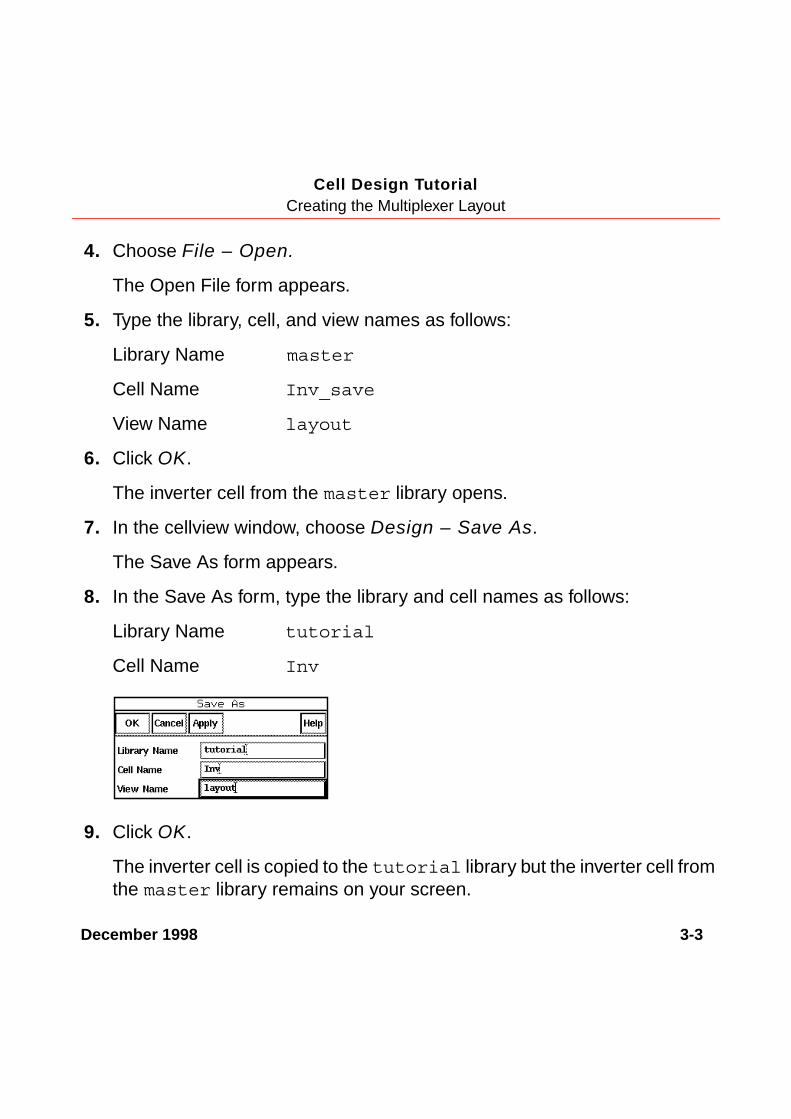
7. In the cellview window, choose Design – Save As.
The Save As form appears.
8. In the Save As form, type the library and cell names as follows:
Library Name tutorial
Cell Name Inv
9. Click OK.
The inverter cell is copied to the tutorial library but the inverter cell fromthe master library remains on your screen.

December 1998 3-4
Cell Design TutorialCreating the Multiplexer Layout
10. To close the inverter cellview from the master library, in the cellviewwindow, choose Window – Close.
You will use the inverter from the tutorial library later in this chapter.
Creating a Hierarchical LayoutIn this chapter, you create a hierarchical design. A hierarchical design is onecontaining instances of other cells. Those cells, in turn, can contain instances ofcells.
You create the multiplexer in this chapter by placing instances of several cellsinside the multiplexer cellview, mux2, as shown in the following figure.
You place the following cells from the tutorial library: mux2_connect,nand2, and Inv, the inverter you created in the previous chapter or just copiedfrom the master library. Most of these cells contain other cells.
Later in this chapter, you flatten the mux2_connect cell, so its contents appearin the top mux2 cellview and it is no longer an instance.
mux2
nand2 Invmux2_connect
ptranA ptranntran ntran
nand2
ptranA ntran
nand2
ptranA ntran
December 1998 3-5
Cell Design TutorialCreating the Multiplexer Layout
In the following sections, you learn to
■ Create the multiplexer layout, mux2.
■ Create and copy the nand instance.
■ Create the inverter instance.
Creating a New Cellview
In this section, you learn to create a layout view for the mux2 cell.
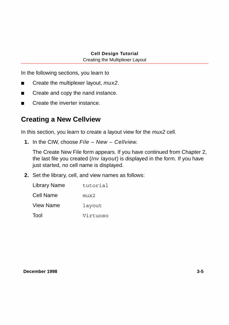
1. In the CIW, choose File – New – Cellview.
The Create New File form appears. If you have continued from Chapter 2,the last file you created (Inv layout) is displayed in the form. If you havejust started, no cell name is displayed.
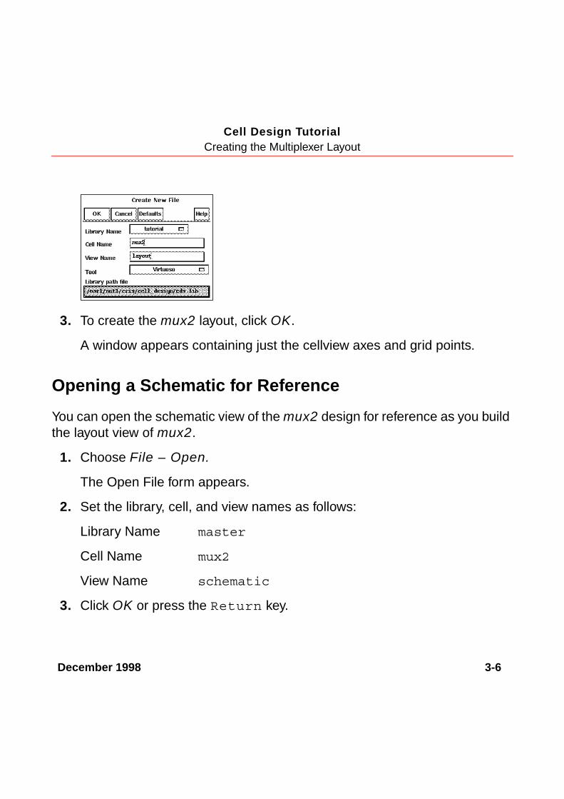
2. Set the library, cell, and view names as follows:
Library Name tutorial
Cell Name mux2
View Name layout
Tool Virtuoso
December 1998 3-6
Cell Design TutorialCreating the Multiplexer Layout
3. To create the mux2 layout, click OK.
A window appears containing just the cellview axes and grid points.
Opening a Schematic for Reference
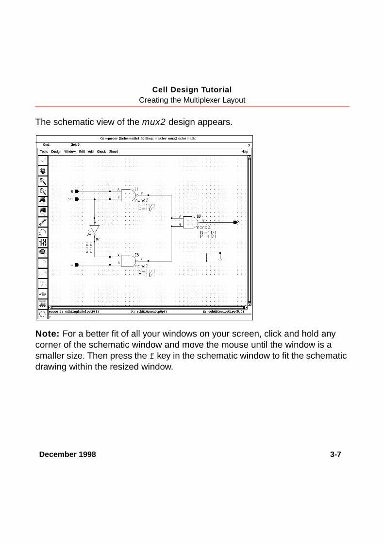
You can open the schematic view of the mux2 design for reference as you buildthe layout view of mux2.
1. Choose File – Open.
The Open File form appears.
2. Set the library, cell, and view names as follows:
Library Name master
Cell Name mux2
View Name schematic
3. Click OK or press the Return key.
December 1998 3-7
Cell Design TutorialCreating the Multiplexer Layout
The schematic view of the mux2 design appears.
Note: For a better fit of all your windows on your screen, click and hold anycorner of the schematic window and move the mouse until the window is asmaller size. Then press the f key in the schematic window to fit the schematicdrawing within the resized window.

December 1998 3-8
Cell Design TutorialCreating the Multiplexer Layout
Creating the First nand2 Instance
You are now ready to place the first instance of the nand2 cell into the mux2cellview.
1. Move the cursor inside the mux2 layout window and press the i key.
The Create Instance form appears. If you have continued from Chapter 2,the last cell you placed (ptransistor) is displayed in the form. If you havejust started, no cell name is displayed.
2. Type the library, cell, and view names as follows:
Library Name master
Cell Name nand2
View Name layout
3. To place the first nand2 cell, click X = 0, Y = 0.
The nand2 cell appears in the mux2 cellview.

December 1998 3-9
Cell Design TutorialCreating the Multiplexer Layout
4. To stop the Instance command, press the Escape key.
The Create Instance form disappears.
5. To fit the design in the window, press the f key.
6. To move to the right of the nand2, start the Pan command by pressing theTab key.
7. Click X = 18.0, Y = 18.0.
Copying the nand2 Instance
You copy the first nand instance to create the second nand instance.
1. To start the Copy command, press the c key.
December 1998 3-10
Cell Design TutorialCreating the Multiplexer Layout
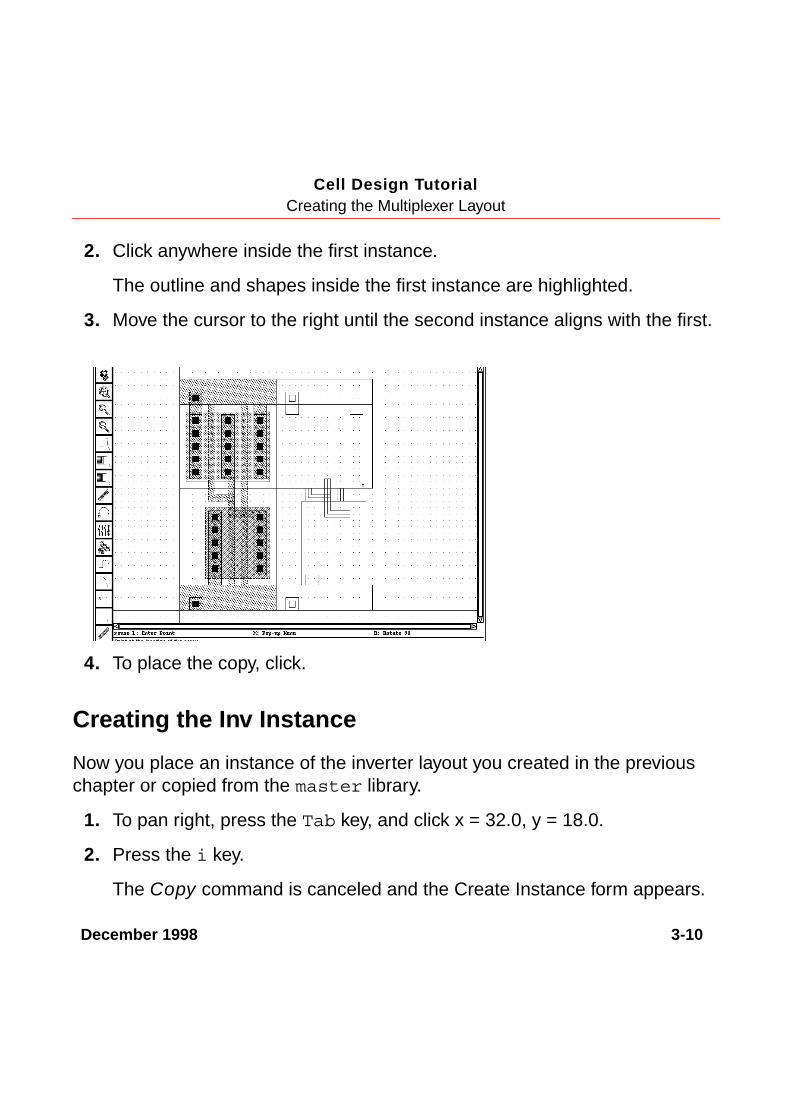
2. Click anywhere inside the first instance.
The outline and shapes inside the first instance are highlighted.
3. Move the cursor to the right until the second instance aligns with the first.
4. To place the copy, click.
Creating the Inv Instance
Now you place an instance of the inverter layout you created in the previouschapter or copied from the master library.
1. To pan right, press the Tab key, and click x = 32.0, y = 18.0.
2. Press the i key.
The Copy command is canceled and the Create Instance form appears.

December 1998 3-11
Cell Design TutorialCreating the Multiplexer Layout
3. In the Create Instance form, type the library, cell, and view names asfollows:
Library Name tutorial
Cell Name Inv
View Name layout
4. You need to mirror the inverter along the X axis. To mirror the inverter, clickSideways.
5. In the cellview, click X = 40, Y = 0 for the instance origin.
6. To stop the Instance command, press the Escape key.
The inverter appears next to the nands.
The inverter is not aligned properly with the nands. You correct this error inthe following section.
The inverter does notalign with the nand.
December 1998 3-12
Cell Design TutorialCreating the Multiplexer Layout
Editing the Inverter in PlaceThe inverter you placed in the previous section does not align properly with thenands. You can correct this error by stretching the top half of the inverter up by1 micron. But you cannot edit the inverter now because you are looking only atan instance of the inverter cell inside the multiplexer.
You could open the inverter cell layout in a separate window and edit the inverterthere, but then you would not be able to see how the inverter aligns with theother instances in the multiplexer.
The Edit in Place command lets you edit the inverter cell while viewing it insidethe multiplexer layout. This way, you can edit the inverter instance as it appearsin this cellview and see how it aligns with the nand next to it.
In the following sections, you edit in place to correct the inverter cell. You learn to
■ Open the inverter cell to edit in place.
■ Stretch the top of the inverter.
■ Return to editing the mux2 cellview.
Opening a Cell to Edit in Place
Open the inverter cell for editing using Edit in Place.
1. Choose Design – Hierarchy – Edit in Place.
The layout editor prompts you to point to a shape in the design to be edited.
2. Click the metal1 polygon at the top or bottom of the inverter.

December 1998 3-13
Cell Design TutorialCreating the Multiplexer Layout
Note: The transistors are pcells (parameterized cells). You cannot editpcells in place because they must be created by compiling (you learn howto compile pcells later in this tutorial). If you accidentally click on a shapeinside one of the pcells, a message says you cannot edit pcells in place.
When you successfully open the inverter using Edit in Place, you might notnotice any change in the display. Look at the window title to see that youare editing the Inv layout.
3. Choose Window – Fit Edit.
The Inv layout data is fitted to the window and the border of the inverter ishighlighted in light brown. This confirms you are editing the inverter cell.You still see the surrounding multiplexer data, but you cannot edit itbecause it is at a different level of the hierarchy.
The title bar showsyou are now editingInv layout.

December 1998 3-14
Cell Design TutorialCreating the Multiplexer Layout
Stretching an Area
Use Stretch to stretch the top of the inverter.
1. Choose Edit – Stretch.
2. To define the area you want to stretch, click X = 29.5, Y = 17.5 and drag thebox to a point above and to the right of the area to be stretched.
Release themouse buttonhere.
To start creating thestretch selection box,click and hold here.

December 1998 3-15
Cell Design TutorialCreating the Multiplexer Layout
3. Release the left mouse button.
The edges you can stretch are highlighted.
The prompt in the CIW reads
Point at the reference point for the stretch
The layout editor often asks for a reference point as you use editingcommands. The reference point is the startpoint for the command; forexample, the starting point from which you move a group of objects. In thiscase, the reference point is the starting point for the stretch.
The boundary of theinstance is still highlightedin light brown.
The edges you canstretch are highlightedin white.

December 1998 3-16
Cell Design TutorialCreating the Multiplexer Layout
4. Click the top edge of the polygon for a reference point. Move the cursor upuntil the edge of the inverter aligns with the nand.
5. To complete the stretch, click.
The inverter and the nand instance now align correctly.
The inverter is still highlighted in light brown to remind you that you areediting this cell, not the multiplexer.
6. To stop the Stretch command, press the Escape key.
Returning to the Multiplexer
While you edit a cell in place, you cannot edit the surrounding data (in this case,the other objects in mux2). When you finish editing the inverter in place, youmust return to editing the multiplexer cell.
Click here to start thestretch.
Drag the edge so italigns with the nand.
December 1998 3-17
Cell Design TutorialCreating the Multiplexer Layout
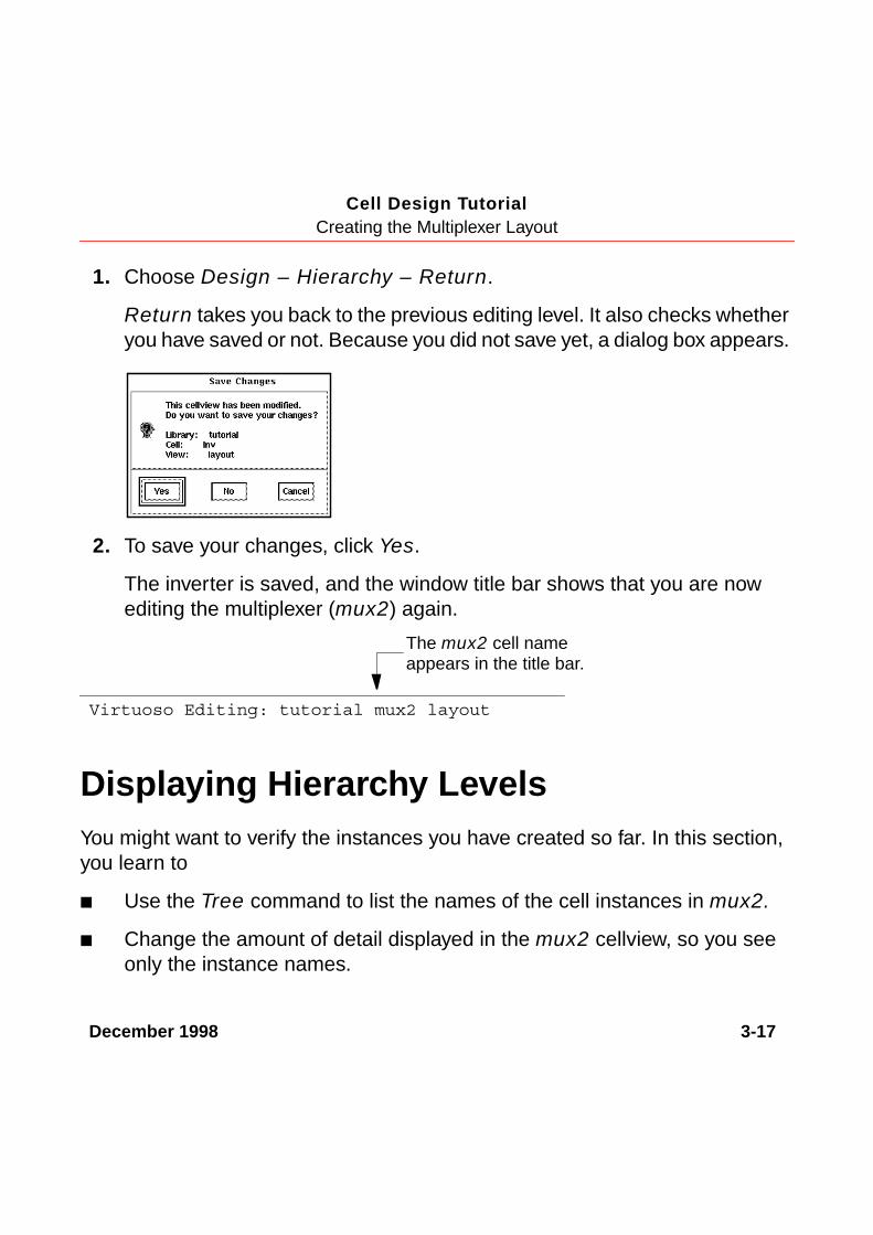
1. Choose Design – Hierarchy – Return.
Return takes you back to the previous editing level. It also checks whetheryou have saved or not. Because you did not save yet, a dialog box appears.
2. To save your changes, click Yes.
The inverter is saved, and the window title bar shows that you are nowediting the multiplexer (mux2) again.
Displaying Hierarchy LevelsYou might want to verify the instances you have created so far. In this section,you learn to
■ Use the Tree command to list the names of the cell instances in mux2.
■ Change the amount of detail displayed in the mux2 cellview, so you seeonly the instance names.
Virtuoso Editing: tutorial mux2 layout
The mux2 cell nameappears in the title bar.

December 1998 3-18
Cell Design TutorialCreating the Multiplexer Layout
Listing the Cells in the Multiplexer
Use the Tree command to list all the cell instances placed in the multiplexer.
1. Choose Design – Hierarchy – Tree.
The Tree form appears.
The Display option lets you choose how much of the hierarchy you want tosee. The top is this cellview and the current cell is the cell you are editing.When you were editing the Inv cell in place, it was the current cell.
Now both the top and current cells are this cellview, mux2.
2. Click OK.

December 1998 3-19
Cell Design TutorialCreating the Multiplexer Layout
A window appears, listing the cells inside the mux2 cellview. The windowdisplayed by Tree is a text window. Commands that list information usuallydisplay the data in a text window.
Tree shows all the hierarchy contained in mux2. It lists all the cell instancesplaced in mux2 and any instances inside those cells. It gives the library,cell, and view name for each instance. It also shows the number ofinstances of a particular cell, in parentheses.
You can use Tree whenever you want to review the levels of hierarchy in adesign.
3. To display the File menu, click File.
You can use the File menu to save the data in the window to a text file orto search through the text.
4. To close the window, choose File – Close Window.
December 1998 3-20
Cell Design TutorialCreating the Multiplexer Layout
Changing Display Levels
At present, you are viewing all the detail in all instances placed inside the mux2cell. You can turn off some of this detail so you see only the outlines of instancesand the master cell name for each instance.
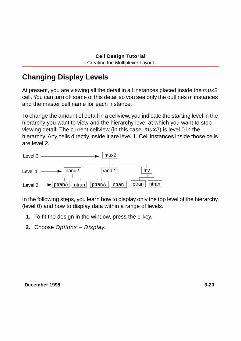
To change the amount of detail in a cellview, you indicate the starting level in thehierarchy you want to view and the hierarchy level at which you want to stopviewing detail. The current cellview (in this case, mux2) is level 0 in thehierarchy. Any cells directly inside it are level 1. Cell instances inside those cellsare level 2.
In the following steps, you learn how to display only the top level of the hierarchy(level 0) and how to display data within a range of levels.
1. To fit the design in the window, press the f key.
2. Choose Options – Display.
Level 0
Level 1
Level 2
mux2
nand2 Inv
ptranA ptranntran ntran
nand2
ptranA ntran
December 1998 3-21
Cell Design TutorialCreating the Multiplexer Layout
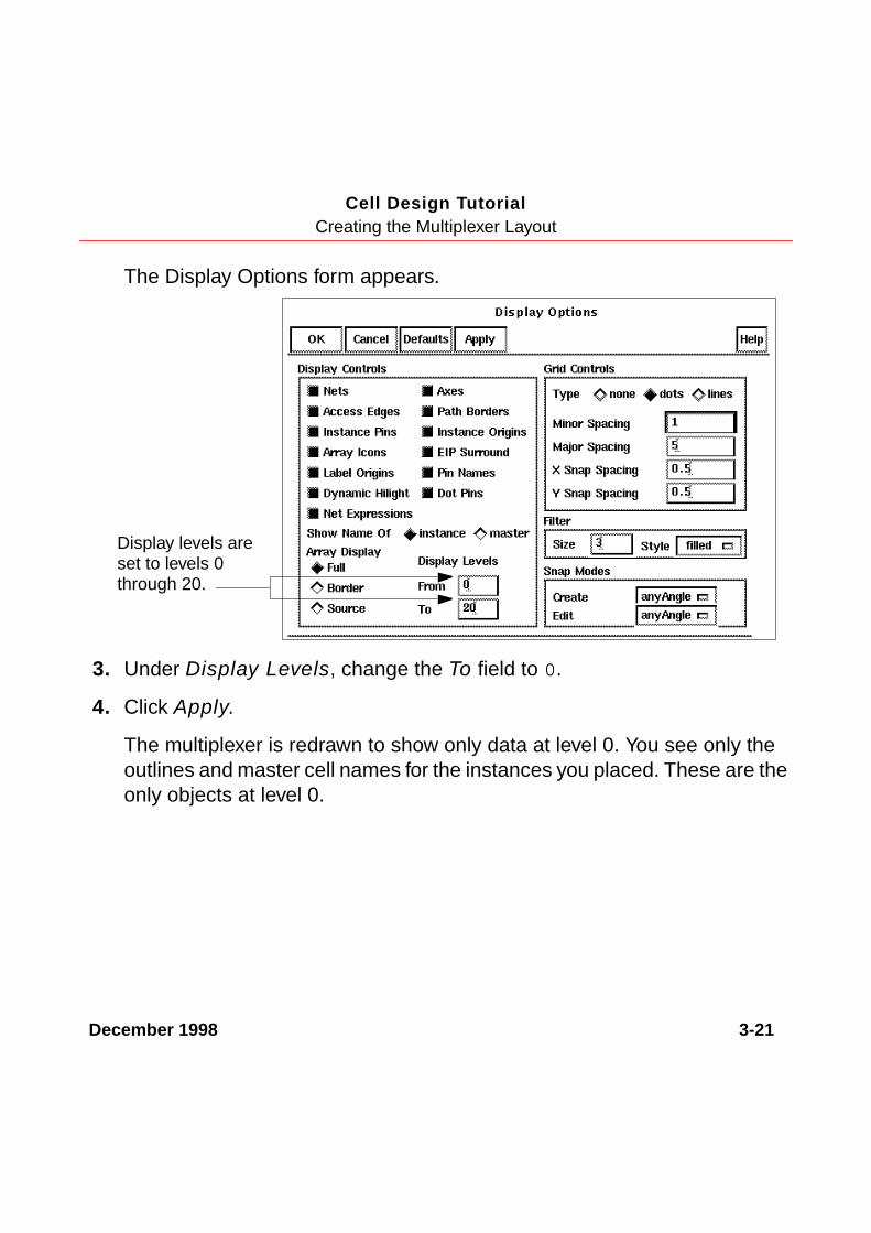
The Display Options form appears.
3. Under Display Levels, change the To field to 0.
4. Click Apply.
The multiplexer is redrawn to show only data at level 0. You see only theoutlines and master cell names for the instances you placed. These are theonly objects at level 0.
Display levels areset to levels 0through 20.

December 1998 3-22
Cell Design TutorialCreating the Multiplexer Layout
The master cell name is not relative to the orientation of the instance; it isjust displayed as large as possible inside the outline.
5. Change the To field to 1.
6. Click Apply.
December 1998 3-23
Cell Design TutorialCreating the Multiplexer Layout
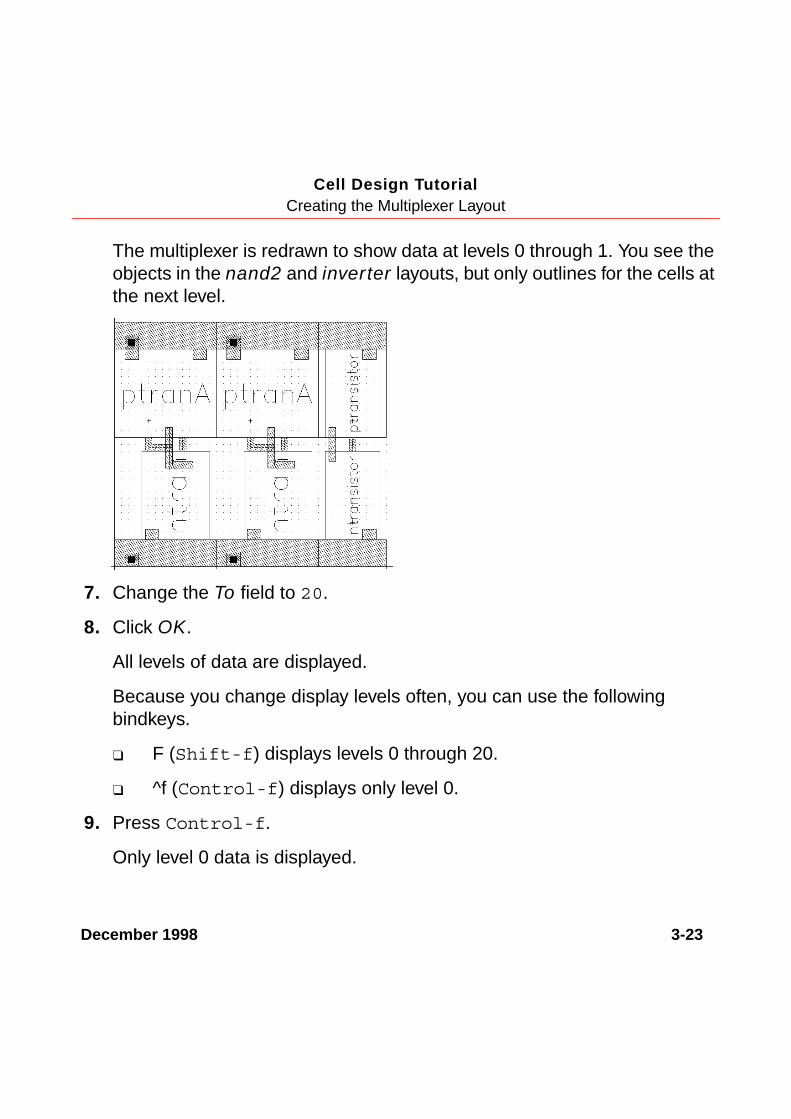
The multiplexer is redrawn to show data at levels 0 through 1. You see theobjects in the nand2 and inverter layouts, but only outlines for the cells atthe next level.
7. Change the To field to 20.
8. Click OK.
All levels of data are displayed.
Because you change display levels often, you can use the followingbindkeys.
❑ F (Shift-f) displays levels 0 through 20.
❑ ^f (Control-f) displays only level 0.
9. Press Control-f.
Only level 0 data is displayed.
December 1998 3-24
Cell Design TutorialCreating the Multiplexer Layout
10. Press Shift-f.
All levels of data are displayed.
Placing and Flattening an InstanceYou still need to place the last nand for the multiplexer. You also need to createthe connections between the instances. The tutorial database contains a layoutcell containing predefined connections for the instances in the multiplexer soyou don’t have to create all the connections yourself. You will create the finalconnections later in this chapter.
Normally, you would create the connections at the top level (level 0). Becauseyou place these connections using a cell instance (level 1), you flatten theinstance after you place it. Flattening the instance moves its contents up to thetop level so it is no longer an instance.
In the following sections, you learn to
■ Copy and place the last nand in the multiplexer.
■ Place the mux2_connect instance containing most of the connections forthe multiplexer.
■ Flatten the mux2_connect instance so it is no longer an instance, movingits contents up one level in the hierarchy.
December 1998 3-25
Cell Design TutorialCreating the Multiplexer Layout
Copying the nand2 Instance Again
Now you copy one of the nand2 instances to the right of the inverter to placethe last nand in the multiplexer. You do this just as you did for the second nandas described in Copying the nand2 Instance on page 3-9. If you feel confident,copy the nand again on your own and skip to the Placing the Connect Cell onpage 3-26.
1. To pan right, press the Tab key and click X = 35.0, y = 18.0.
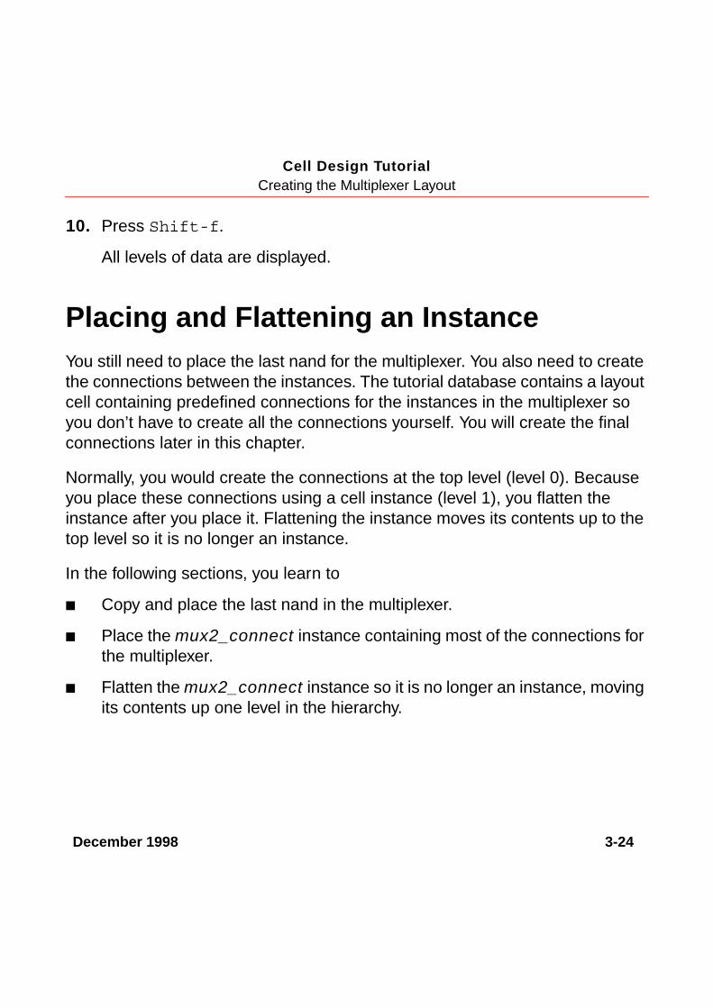
2. To start the Copy command, click the Copy command icon in the iconmenu.
The Copy form appears.
3. Click anywhere inside the second nand2 instance.
The outline and shapes inside the instance are highlighted.
Click the Copycommand icon.

December 1998 3-26
Cell Design TutorialCreating the Multiplexer Layout
4. Move the cursor to the right until the last nand2 aligns with the inverter.
5. To place the copy, click.
6. To stop the Copy command, press the Escape key.
7. To fit the entire design in the multiplexer window, press the f key.
Placing the Connect Cell
Use Instance to place a layout cell containing predefined connections for theinstances in the multiplexer.
December 1998 3-27
Cell Design TutorialCreating the Multiplexer Layout
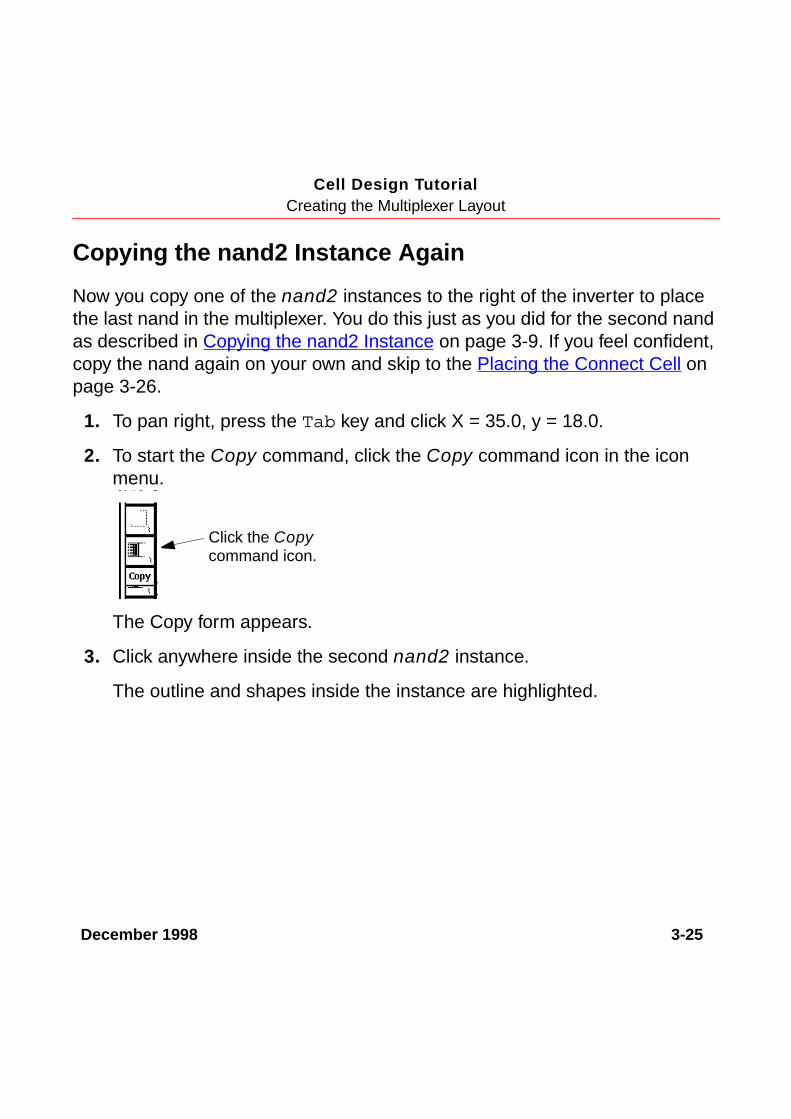
1. To display the Create Instance form, click the Instance command icon inthe icon menu.
The Create Instance form appears.
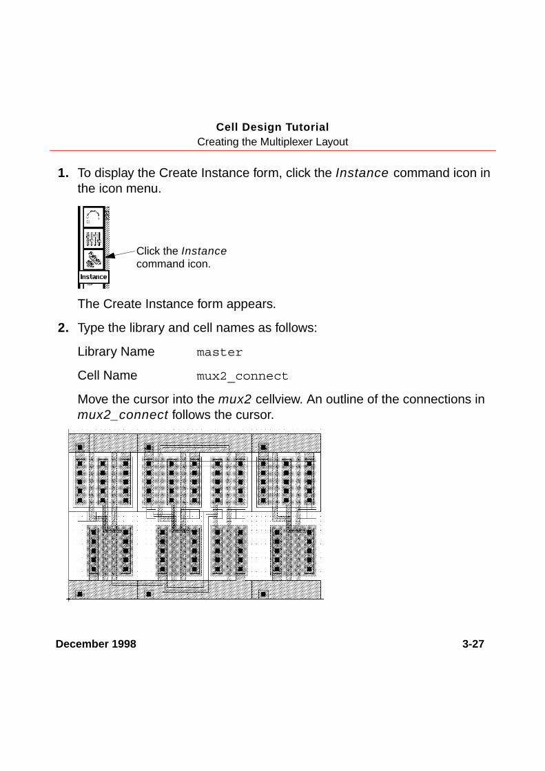
2. Type the library and cell names as follows:
Library Name master
Cell Name mux2_connect
Move the cursor into the mux2 cellview. An outline of the connections inmux2_connect follows the cursor.
Click the Instancecommand icon.

December 1998 3-28
Cell Design TutorialCreating the Multiplexer Layout
3. Move the cursor to X = 0, Y = 0.
The poly1 connections at the top and bottom of the multiplexer shouldalign exactly.
4. To place the mux2_connect cell, click.
5. To stop the Instance command, press the Escape key.
Flattening the Connect Cell
Normally, you would create the connections between the instances in themultiplexer at the top level (level 0); they would not be in a cell. Themux2_connect cell was provided to save you time. You use Flatten to movethe data in mux2_connect up to level 0 so it is no longer an instance.
1. To display outlines of the instances, press Control-f.
It is often easier to select a cell instance while viewing only instanceoutlines.
2. Choose Edit – Hierarchy – Flatten.
The Flatten form appears. You need to move the contents ofmux2_connect up just one level (from level 1 to level 0). The default formsettings are set correctly.
December 1998 3-29
Cell Design TutorialCreating the Multiplexer Layout
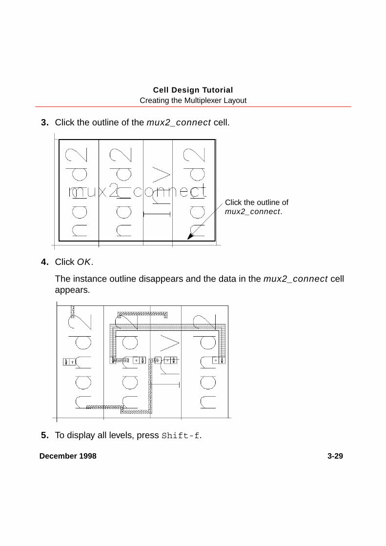
3. Click the outline of the mux2_connect cell.
4. Click OK.
The instance outline disappears and the data in the mux2_connect cellappears.
5. To display all levels, press Shift-f.
Click the outline ofmux2_connect.

December 1998 3-30
Cell Design TutorialCreating the Multiplexer Layout
Saving the Design
It is always a good idea to save your design periodically.
➤ To save your design, press the F2 key.
The multiplexer is saved to disk.
Using Path StitchingNot all the connections for the multiplexer were in the mux2_connect cell youplaced in the previous section. You still need to connect the output of the firstnand2 instance to one of the inputs for the last nand2.
You use Path to create the final connections. You cannot create a path on asingle layer all the way across the multiplexer; so you use path stitching tochange layers within the path. Path stitching automatically changes the pathfrom one layer to another, placing an appropriate contact to connect the twolayers. The Path command chooses the contact for you from the technology file.
In this section, you learn to
■ Turn gravity off so you can create the path.
■ Start the path on the metal1 layer.
■ Switch to the metal2 layer, automatically placing a metal1-to-metal2contact.
■ Switch back to metal1, then to poly1, each time placing contacts.
December 1998 3-31
Cell Design TutorialCreating the Multiplexer Layout
Turning Gravity Off
Snapping the cursor to objects is called gravity. Gravity is turned on by defaultand is helpful when creating instances and devices. In this section, you turngravity off to make it easier to create a path. You can toggle the gravity on andoff using either the Layout Editor Options form or the g bindkey.
➤ To turn gravity off, move the cursor inside the mux2 layout and press the gkey.
December 1998 3-32
Cell Design TutorialCreating the Multiplexer Layout
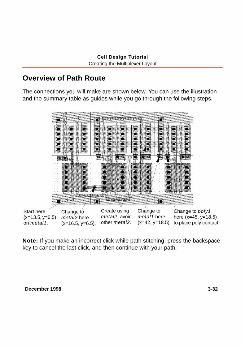
Overview of Path Route
The connections you will make are shown below. You can use the illustrationand the summary table as guides while you go through the following steps.
Note: If you make an incorrect click while path stitching, press the backspacekey to cancel the last click, and then continue with your path.
Start here(x=13.5, y=6.5)on metal1.
Change tometal2 here(x=16.5, y=6.5).
Create usingmetal2; avoidother metal2.
Change tometal1 here(x=42, y=18.5).
Change to poly1here (x=45, y=18.5)to place poly contact.

December 1998 3-33
Cell Design TutorialCreating the Multiplexer Layout
Starting the Path on metal1
1. In the LSW, click the metal1 dg layer.
2. In the cellview window, press the p key.
The Create Path form appears. Notice, the path width is set to 1 micron.This width is defined in the technology file as a property of the metal1layer.
3. To start the path, click X = 13.5, Y = 6.5.
Table 3-1 Summary of Path Route
Number ofpoints
Location Angle Layer Purpose
First x=13.5, y=6.5 orthogonal metal1 Start path
Second x=16.5, y=6.5 orthogonal metal1 Create path
Third x=16.5, y=6.5 orthogonal metal2 Place contact
Fourth x=22.5, y=23.5 L90XFirst metal2 Create path
Fifth x=42, y=18.5 L90XFirst metal2 Create path
Sixth x=42, y=18.5 L90XFirst metal1 Place contact
Seventh x=45, y=18.5 L90XFirst metal1 Create path
Eight x=45, y=18.5 L90XFirst poly1 Place contact
Ninth x=45, y=18.5 L90XFirst poly1 End path
December 1998 3-34
Cell Design TutorialCreating the Multiplexer Layout
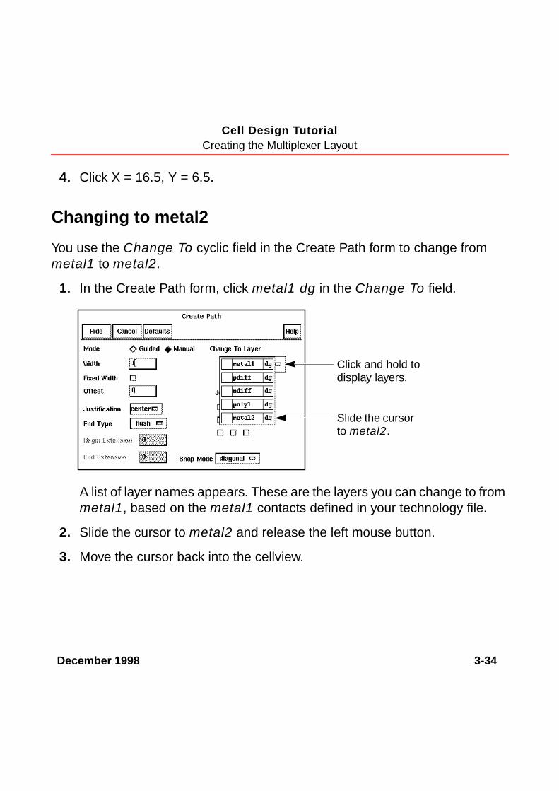
4. Click X = 16.5, Y = 6.5.
Changing to metal2
You use the Change To cyclic field in the Create Path form to change frommetal1 to metal2.
1. In the Create Path form, click metal1 dg in the Change To field.
A list of layer names appears. These are the layers you can change to frommetal1, based on the metal1 contacts defined in your technology file.
2. Slide the cursor to metal2 and release the left mouse button.
3. Move the cursor back into the cellview.
Click and hold todisplay layers.
Slide the cursorto metal2.

December 1998 3-35
Cell Design TutorialCreating the Multiplexer Layout
A metal1-to-metal2 contact appears on top of your cursor.
4. To anchor the contact, click again on X = 16.5, y = 6.5.
The entry layer shown at the top of the LSW changes to metal2. You arenow entering points on metal2. The path width changes to 2 microns, thewidth set in the technology file for the metal2 layer.
5. In the Create Path form, change the Snap Mode to L90XFirst.
6. Move the cursor back to the cellview.
7. Click X = 22.5, Y = 23.5.
8. Click X = 42, Y = 18.5.
Metal1-to-metal2contact (via)
December 1998 3-36
Cell Design TutorialCreating the Multiplexer Layout
Completing the Path
To complete the path, you change the path layer two more times: to metal1 andthen to poly1.
1. In the Create Path form, choose metal1 from the Change To field.
2. Move the cursor back into the cellview.
A metal2-to-metal1 contact appears on top of your cursor.
3. To anchor the contact, click again on X = 42, y = 18.5.
4. Click X = 45, Y = 18.5.
5. In the Create Path form, choose poly1 from the Change To field.
A metal1-to-poly1 contact appears on top of your cursor.
6. To anchor the contact, click again on X = 45, Y = 18.5.
7. To complete the path, check that your cursor is on X = 45, y = 18.5 andpress Return.
The connections for the multiplexer are now complete.
8. To stop the Path command, press the Escape key.
9. To save your design, press the F2 key.
December 1998 3-37
Cell Design TutorialCreating the Multiplexer Layout
Creating PinsNow that all the connections are complete, you need to add some informationused by other Cadence® tools.
You need to add net labels to help you diagnose problems found by the LayoutVersus Schematic (LVS) program. You run LVS in the next chapter.
You also need to create pins. Pins are used by Cadence tools as follows:
■ Pins define the connectivity between hierarchy levels. That is, a pinindicates where this cell can connect to routing or to other instances whenthe cell is placed into a larger design.
■ Pins specify the access directions for Cadence routing tools.
■ The LVS program checks to see if you have placed labels that conflict withthe nets you define for the pins.
In this section, you
■ Create pins and label them.
■ Save the multiplexer design to disk.
About Pins
Pins show what areas of the multiplexer can connect to routing or other cellswhen you place an instance of the mux2 into another design cell.
Note: You create pins coincident with shapes in the instances placed in mux2.If you make a mistake, it is easier to select and correct pins if the instances in

December 1998 3-38
Cell Design TutorialCreating the Multiplexer Layout
mux2 are unselectable. If you need to make instances unselectable during thefollowing steps, click the button next to Inst (Instances) in the LSW so it is empty.
Creating Pins
You will create six pins in the mux2 cellview. The pins have differentcharacteristics. This table summarizes the characteristics of the pins you willcreate in the following exercise.
1. In the LSW, click the metal1 dg layer.
2. Choose Create – Pin.
The Create Symbolic Pin form appears. You will use shape pins in thistutorial, not symbolic pins.
PinInput/Outputtype
Access direction Layer
vdd! I/O top, left, right metal1 dg
gnd! I/O bottom, left, right metal1 dg
A input top, bottom metal2 dg
B input bottom metal2 dg
SEL input bottom metal2 dg
Y output right metal1 dg

December 1998 3-39
Cell Design TutorialCreating the Multiplexer Layout
3. To open the Create Shape Pin form, click the button next to shape pin.
The Create Shape Pin form appears.
4. In the Create Shape Pin form, type the following in the Terminal Namesfield.
vdd! gnd! A B SEL Y
You can type any number of names in the Create Shape Pin or CreateSymbolic Pin form. Each pin you create is assigned the next name, fromleft to right, in the Terminal Names field.
5. To associate the name with the pin, click Create Label.
Click shape pin.
December 1998 3-40
Cell Design TutorialCreating the Multiplexer Layout
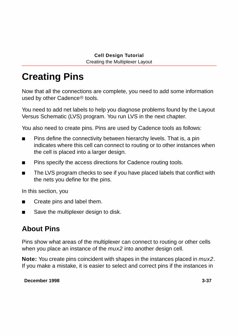
6. Set the access direction to top, left, and right by clicking bottom to turn itoff.
7. Create the rectangle for the vdd! pin coincident with the power line at thetop of the multiplexer.
Type the names ofthe pins you wantto create.
Set the pin accessdirection to top,left, and right.
SetCreateLabel on.
Start the vdd!pin at thiscorner.
Finish thevdd! pinat thiscorner.
The vdd!appearsafter youclick thesecondcorner.

December 1998 3-41
Cell Design TutorialCreating the Multiplexer Layout
The name of the pin (vdd!) appears near the cursor.
A dashed line extends from the first corner of the pin to the name, showingthe pin name is attached to the pin. If you move or delete the pin, theattached label will also be moved or deleted.
8. Move the cursor so the vdd! text appears near the left side of the pin, thenclick.
The name vdd! disappears from the Create Shape Pin form. The first namelisted is now gnd! (the ground pin).
9. In the Create Shape Pin form, turn off the top access direction and turn onthe bottom access direction.
Place the pin name here.
The terminalname for thenext pin youcreate is gnd!(ground).
Set the accessdirection tobottom, left,and right.

December 1998 3-42
Cell Design TutorialCreating the Multiplexer Layout
10. Create the rectangle for the gnd! pin coincident with the ground line at thebottom of the multiplexer.
11. In the LSW, click metal2 dg.
12. In the Create Shape Pin form, set the I/O Type to input.
13. Enter this information in the Create Shape Pin form before you create eachinput pin for terminals A, B, and SEL.
For Pin. . . Set the Access Direction to. . .
A top and bottom
B bottom
SEL bottom
Start thegnd! pin atthis corner.
Finish thegnd! pinat thiscorner.
Place the gnd! pin name here.

December 1998 3-43
Cell Design TutorialCreating the Multiplexer Layout
Use this illustration to determine the location for each pin.
After you create the pins shown in the illustration, the pin form now showsonly one pin to create: the Y pin for the multiplexer output.
14. Click the metal1 dg layer in the LSW.
15. Change the I/O type to output in the Create Shape Pin form.
16. Turn off all access directions except right.
Terminal name = APin layer = metal2Access direction = topand bottom
Terminal name = BPin layer = metal2Access direction = bottom
Terminal name = SELPin layer = metal2Access direction = bottom

December 1998 3-44
Cell Design TutorialCreating the Multiplexer Layout
17. Create the Y output pin as shown below.
Place the Y pin name anywhere near the pin.
18. To stop the Pin command, press the Escape key.
Saving the Design
➤ To save your design, press the F2 key.
The multiplexer is saved to disk.
Closing the mux2 Schematic
Because your design is finished, you can close the mux2 schematic.
➤ To close the mux2 schematic, in the schematic window,choose Window – Close.
Pin layer = metal1Terminal name = YAccess direction = rightI/O Type = output
Finish the Y pin atthis corner.
Start the Y pinat this corner.
December 1998 3-45
Cell Design TutorialCreating the Multiplexer Layout
SummaryIn this section, you learned how to use the layout editor to create hierarchicaldesigns. You also learned more about layout editor create and edit commands.Specifically, you
■ Created a hierarchical layout.
❑ Created instances.
❑ Copied instances.
❑ Mirrored instances.
■ Used Edit in Place.
❑ Opened a lower-level cell for editing.
❑ Returned to the previous level.
❑ Saved during Edit in Place.
■ Stretched an area.
❑ Selected an area.
❑ Used a reference point.
■ Displayed different hierarchy levels.
❑ Displayed a list of cells in the current cellview
❑ Viewed instance outlines and master names only

December 1998 3-46
Cell Design TutorialCreating the Multiplexer Layout
❑ Displayed a range of levels.
❑ Used bindkeys to change display levels.
■ Flattened the hierarchy in one cell.
■ Created paths using path stitching.
❑ Turned gravity off.
❑ Changed layers.
❑ Automatically placed contacts.
■ Created labels.
■ Created pins.
■ Saved the design.
■ Used bindkeys.
❑ Create Instance [i].
❑ Fit All [f].
❑ Pan [Tab].
❑ Copy [c].
❑ Display Levels 0–20 [Shift-f].
❑ Display Levels 0–0 [Control-f].
❑ Gravity toggle [g].
❑ Save [F2].

December 1998 3-47
Cell Design TutorialCreating the Multiplexer Layout
■ Used the icon menu.
❑ Copy.
❑ Create Instance.