crd1611 ds975rd5 v0
TRANSCRIPT

Chipsmall Limited consists of a professional team with an average of over 10 year of expertise in the distribution
of electronic components. Based in Hongkong, we have already established firm and mutual-benefit business
relationships with customers from,Europe,America and south Asia,supplying obsolete and hard-to-find components
to meet their specific needs.
With the principle of “Quality Parts,Customers Priority,Honest Operation,and Considerate Service”,our business
mainly focus on the distribution of electronic components. Line cards we deal with include
Microchip,ALPS,ROHM,Xilinx,Pulse,ON,Everlight and Freescale. Main products comprise
IC,Modules,Potentiometer,IC Socket,Relay,Connector.Our parts cover such applications as commercial,industrial,
and automotives areas.
We are looking forward to setting up business relationship with you and hope to provide you with the best service
and solution. Let us make a better world for our industry!
Contact usTel: +86-755-8981 8866 Fax: +86-755-8427 6832
Email & Skype: [email protected] Web: www.chipsmall.com
Address: A1208, Overseas Decoration Building, #122 Zhenhua RD., Futian, Shenzhen, China

Copyright Cirrus Logic, Inc. 2013(All Rights Reserved)
Cirrus Logic, Inc.http://www.cirrus.com
BottomBottom
Top
CRD1611-8W
CRD1611-8W
8 Watt Reference DesignFeatures
� Quasi-resonant Flyback with Constant-current Output
� Flicker-free Dimming
� Line Voltage 230VAC, ±10%
� Rated Input Power: 8.0W
� Rated Output Power: 6.6W
� Output Voltage: 11.0V to 12.6V
� Efficiency: 83% at 550mA, for 4LEDs in series
� Low Component Count
� Supports Cirrus Logic Product CS1611
General Description
The CRD1611-8W reference design demonstrates the
performance of the CS1611 resonant mode AC/DC
dimmable LED driver IC with a 550mA output driving
4LEDs in series. It offers best-in-class dimmer
compatibility with leading-edge, trailing-edge, and digital
dimmers. The form factor is targeted to fit into many LED
bulb applications (A19, PAR).
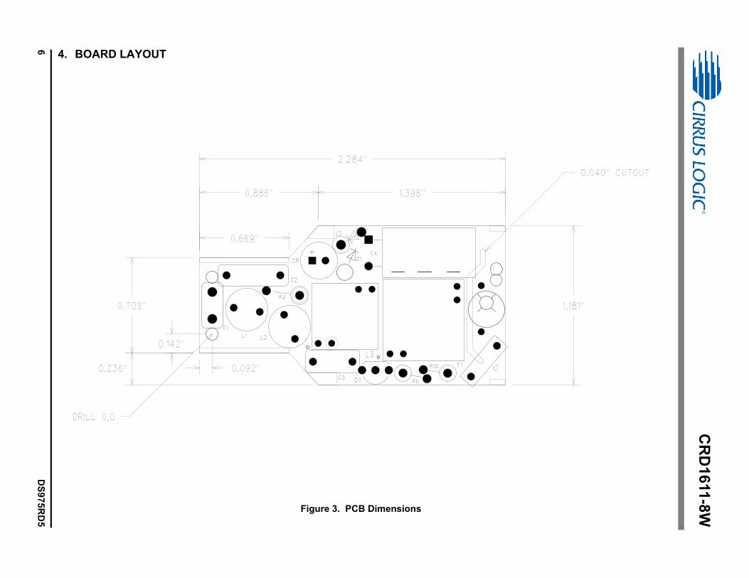
DIMENSIONS (OVERALL)
Length Width Height
For more information, see Figure 3.
ORDERING INFORMATION
CRD1611-8W-Z 8 Watt Reference Design
Supports CS1611
2.284 58mm 1.181 29.9mm 0.652 16.5mm
FEB‘12
DS975RD5
CRD1611-8W
2 DS975RD5
Contacting Cirrus Logic SupportFor all product questions and inquiries contact a Cirrus Logic Sales Representative. To find the one nearest to yougo to www.cirrus.com
IMPORTANT NOTICE
Cirrus Logic, Inc. and its subsidiaries ("Cirrus") believe that the information contained in this document is accurate and reliable. However, the information is subjectto change without notice and is provided "AS IS" without warranty of any kind (express or implied). Customers are advised to obtain the latest version of relevantinformation to verify, before placing orders, that information being relied on is current and complete. All products are sold subject to the terms and conditions of salesupplied at the time of order acknowledgment, including those pertaining to warranty, indemnification, and limitation of liability. No responsibility is assumed by Cirrusfor the use of this information, including use of this information as the basis for manufacture or sale of any items, or for infringement of patents or other rights of thirdparties. This document is the property of Cirrus and by furnishing this information, Cirrus grants no license, express or implied under any patents, mask work rights,copyrights, trademarks, trade secrets or other intellectual property rights. Cirrus owns the copyrights associated with the information contained herein and givesconsent for copies to be made of the information only for use within your organization with respect to Cirrus integrated circuits or other products of Cirrus. This con-sent does not extend to other copying such as copying for general distribution, advertising or promotional purposes, or for creating any work for resale.
CERTAIN APPLICATIONS USING SEMICONDUCTOR PRODUCTS MAY INVOLVE POTENTIAL RISKS OF DEATH, PERSONAL INJURY, OR SEVERE PROP-ERTY OR ENVIRONMENTAL DAMAGE ("CRITICAL APPLICATIONS"). CIRRUS PRODUCTS ARE NOT DESIGNED, AUTHORIZED OR WARRANTED FORUSE IN PRODUCTS SURGICALLY IMPLANTED INTO THE BODY, AUTOMOTIVE SAFETY OR SECURITY DEVICES, LIFE SUPPORT PRODUCTS OR OTHERCRITICAL APPLICATIONS. INCLUSION OF CIRRUS PRODUCTS IN SUCH APPLICATIONS IS UNDERSTOOD TO BE FULLY AT THE CUSTOMER'S RISKAND CIRRUS DISCLAIMS AND MAKES NO WARRANTY, EXPRESS, STATUTORY OR IMPLIED, INCLUDING THE IMPLIED WARRANTIES OF MERCHANT-ABILITY AND FITNESS FOR PARTICULAR PURPOSE, WITH REGARD TO ANY CIRRUS PRODUCT THAT IS USED IN SUCH A MANNER. IF THE CUSTOMEROR CUSTOMER'S CUSTOMER USES OR PERMITS THE USE OF CIRRUS PRODUCTS IN CRITICAL APPLICATIONS, CUSTOMER AGREES, BY SUCH USE,TO FULLY INDEMNIFY CIRRUS, ITS OFFICERS, DIRECTORS, EMPLOYEES, DISTRIBUTORS AND OTHER AGENTS FROM ANY AND ALL LIABILITY, IN-CLUDING ATTORNEYS' FEES AND COSTS, THAT MAY RESULT FROM OR ARISE IN CONNECTION WITH THESE USES.
Cirrus Logic, Cirrus, the Cirrus Logic logo designs, EXL Core, the EXL Core logo design, TruDim, and the TruDim logo design are trademarks of Cirrus Logic, Inc.All other brand and product names in this document may be trademarks or service marks of their respective owners.
IMPORTANT SAFETY INSTRUCTIONS
Read and follow all safety instructions prior to using this demonstration board.
This Engineering Evaluation Unit or Demonstration Board must only be used for assessing IC performance in a laboratory setting. This product is not intended for any other use or incorporation into products for sale.
This product must only be used by qualified technicians or professionals who are trained in the safety procedures associated with the use of demonstration boards.
Risk of Electric Shock
• The direct connection to the AC power line and the open and unprotected boards present a serious risk of electric shock and can cause serious injury or death. Extreme caution needs to be exercised while handling this board.
• Avoid contact with the exposed conductor or terminals of components on the board. High voltage is present on exposed conductor and it may be present on terminals of any components directly or indirectly connected to the AC line.
• Dangerous voltages and/or currents may be internally generated and accessible at various points across the board.
• Charged capacitors store high voltage, even after the circuit has been disconnected from the AC line.
• Make sure that the power source is off before wiring any connection. Make sure that all connectors are well connected before the power source is on.
• Follow all laboratory safety procedures established by your employer and relevant safety regulations and guidelines, such as the ones listed under, OSHA General Industry Regulations - Subpart S and NFPA 70E.
Suitable eye protection must be worn when working with or around demonstration boards. Always comply with your employer’s policies regarding the use of personal protective equipment.
All components and metallic parts may be extremely hot to touch when electrically active.

CRD1611-8W
DS975RD5 3
1. INTRODUCTION
The CS1611 is a 230VAC quasi-resonant flyback mode dimmable LED controller IC. The CS1611 uses a digital con-
trol algorithm that is optimized for high efficiency and >0.9 power factor over an input voltage range (207VAC to
253VAC). The CS1611 integrates a critical conduction mode (CRM) boost converter that provides power factor cor-
rection and dimmer compatibility with a constant output current, quasi-resonant flyback stage. An adaptive dimmer
compatibility algorithm controls the boost stage and dimmer compatibility operation mode to enable flicker-free op-
eration to <2% output current with leading-edge, trailing-edge, and digital dimmers.
The CRD1611-8W board is optimized to deliver low system cost in a high-efficiency, flicker-free, phase-dimmable,
solid-state lighting (SSL) solution for incandescent lamp replacement applications. The feedback loop is closed
through an integrated digital control system within the IC. The variation in switching frequency also provides a
spread-frequency spectrum, thus minimizing the conducted EMI filtering requirements. Protection algorithms such
as output open/short, current-sense resistor open/short, and overtemperature thermistors protect the system during
abnormal conditions. Details of these features are provided in the CS1611 data sheet.
The CRD1611-8W board demonstrates the performance of the CS1611. This reference board has been designed
for an output load of 4LEDs in series at 550mA (12.0V typical).
This document provides the schematic for the board. It includes oscilloscope screen shots that indicate various op-
erating waveforms. Graphs are also provided that document the performance of the board in terms of Efficiency vs.
Line Voltage, Output Current vs. Line Voltage, and Output Current vs. Dim Angle for the CS1611 dimmable LED
controller IC. Extreme caution needs to be exercised while handling this board. This board is to be used by trained
professionals only.

CR
D1
611
-8W
4D
S9
75
RD
5
2. SCHEMATIC
600-00543-Z1_Rev_A3JWJW
SHEETOFSHEET
ENGINEER
DATE
DRAWN BY
PART #
SHEET
4/30/2012
SCH.,CRD1611-8W-Z
1 1
TITLE
SIZE B
INITIAL RELEASEA.0
DATEDESCRIPTIONREV
11/18/11
NOTES: UNLESS OTHERWISE SPECIFIED:
1. ALL RESISTOR VALUES ARE IN OHMS.
CHANGED R21 TO A 10_5 OHM RES. ADDED C12 FOR ASSEMBLY CHANGE A1
ECO
915
ONLY. NOT REFLECTED IN CURRENT PCB AS A C12 FOOTPRINT.12/22/11
917 CHANGED C5 TO EL LO ESRA2 1/6/12
A3959 CHANGED U1 PIN 6 & 7 PINNAMES TO NC 04/30/12
F1 1A
1
+
3
2
-
4
BR1HD04-T
C1
4700pF
C2
0.1UF
C3
0.033UF
L14.7mH
L24.7mH
R1 4.7K
R2 4.7K4
3
2
1
7A
8B
T1RM06-CL01
21
54
L3RM05-CL01
D1
STTH1R06
C4
4.7uFELEC
1BSTA
UX
2IAC
3CLA
MP
4SG
ND
5SOURCE
6NC
7NC
8IP
K
9FB
GA
IN
10EOTP
11FBSENSE
12
GN
D
13GD
14VDD
15FBAUX
16
BSTO
UT
PA
DTH
ERM
U1
CS1611-FSZ
12
D2
STTH1L06A
1 2CY 2200pF12
D3
SS26-TP
R527K1%
D7
S1G-13-F
D4
1N4148W
Z1
SMAZ16-TP16V
C8
2.2uFX7R
R151.50M
R141.50M
R71.50M
R81.50M
R11 22.1K
R1722.1K
R13120K
D5BAV23S-7-F
R10
22 OHM
C9
0.33uFX7R
C6
22uFELEC
R1251 OHM
Q1
ZVN4106FTA
Q2
STD1NK60T4R9 47 OHM
R24
47 OHM
C10
1.0UFX7R
R34.7K
Q3
FQN1N50CTA
R19 47 OHM
R1814.0K
-t NTC
100K
C7
100pFCOG
R20 1K
R2110.5
R235.6K
R2269.8K
S
D
G
Q4
STD1NK80ZT4
C11
47pFC0G
PCB DWG- 240-00543-Z1
ASSY DWG- 603-00543-Z1
SCHEMATIC DWG 600-00543-Z1
LBL SUBASSY PROD ID AND REV
E1
LINE
E2
NEUTRAL
E3
LED+
E4
LED-
C5
100uFELEC
R42K
2W
Z2P6KE350A300V
D6SBR130S3-730V
D8
SBR130S3-730V
R6
2K2W
R162K2W
C12
0.01UFX7R
Figure 1. Schematic

CRD1611-8W
DS975RD5 5
3. BILL OF MATERIALS _ _
Item Rev Description Qty Reference Designator MFG MFG P/N
1 A DIODE RECT 400V 0.8A NPB MINIDIP 1 BR1 DIODES INC HD04-T
2 A CAP 4700PF ±10% 1000V X7R NPb 1206 1 C1 MURATA GRM31BR73A472KW01L
3 A CAP 0.1UF ±5% 400V MTL FLM RAD 1 C2 Panasonic ECQE4104JF
4 A CAP 0.033uF ±10% 400V MTL NPb RAD 1 C3 PANASONIC ECQE4333KF
5 A CAP 4.7uF 450V ±20% NPb RAD 10x20 1 C4 PANASONIC-ECG ECA2WHG4R7
6 A CAP 100uF ±20% 25V EL LO ESR NPb RD 1 C5 PANASONIC EEUFM1E101
7 A CAP 22uF ±20% 35V ELEC NPb RAD 1 C6 PANASONIC EEA-GA1V220H
8 A CAP 100pF ±5% 50V C0G NPb 0603 1 C7 KEMET C0603C101J5GAC
9 A CAP 2.2uF ±10% 25V X7R NPb 0805 1 C8 MURATA GRM21BR71E225KA73L
10 A CAP 0.33UF ±10% 50V X7R NPb 0603 1 C9 TDK C1608X7R1H334K
11 A CAP 1.0uF 10% 25V X7R NPb 0603 1 C10 MURATA GRM188R71E105KA12D
12 A CAP 47pF ±5% 1000V C0G NPb 1206 1 C11 JOHANSON DIELECTRICS 102R18N470JV4E
12a A CAP 0.01uF ±10% 630V X7R NPb 1206 1 C12 MURATA GRM31BR72J103KW01L
13 A CAP 2200PF +80/-20% 2KV CER NPb RAD 1 CY MURATA DEBE33D222ZA2B
14 A DIODE FAST 600V 1A NPb DO-41 1 D1 ST STTH1R06
15 A DIODE ULT FAST 600V 1A NPb SMA 1 D2 ST MICROELECTRONICS STTH1L06A
16 A DIODE SKY RECT 60V 2A NPb DO-214AC 1 D3 MICRO COMMERCIAL(MCC) SS26-TP
17 A DIODE FAST SW 75V 350mW NPb SOD123 1 D4 DIODES INC 1N4148W-7-F
18 A DIODE SWT 250V 0.4A NPb SOT-23 1 D5 DIODES INC BAV23S-7-F
19 A DIODE RECT 30V 1A NPb SOD-323 2 D6 D8 DIODES INC SBR130S3-7
20 A DIODE RECT 400V 1A NPb SMA 1 D7 DIODES INC S1G-13-F
21 A FUSE 1A 250V TLAG NPb RAD 1 F1 LITTLE FUSE 39211000440
22 A IND 4.7mH ±10% 17.6 OHM 350 DIA TH 2 L1 L2 COILCRAFT RFB0807-472L
23 A XFMR 6.8mH ±10% 10KHz NPb TH 1 L3 KUNSHAN EAGERNESS RM05-CL01
24 A THERM 100K OHM ±5% 0.10mA NPb 0603 1 NTC MURATA NCP18WF104J03RB
25 A TRAN MOSFET nCH 60V.2A NPb SOT23-3 1 Q1 DIODES INC ZVN4106FTA
26 A TRAN MOSFET nCH 1.0A 600V NPb DPAK 1 Q2 ST MICROELECTRONICS STD1NK60T4
27 A TRAN MOSFET nCH 0.38A 500V NPb TO92 1 Q3 FAIRCHILD FQN1N50CTA
28 A TRAN MOSFET nCH 1A 800V NPb DPAK 1 Q4 ST MICROELECTRONICS STD1NK80ZT4
29 A RES 4.7k OHM 1/4W ±5% 1206 FILM 2 R1 R2 DALE CRCW1206472J
30 A RES 4.70K OHM 1/10W ±1% NPb 0603 1 R3 PANASONIC ERJ3EKF4701V
31 A RES PWR 2.0K OHM 2W ±5% NPb AXL 3 R4 R6 R16 VISHAY PR02000202001JR500
32 A RES 27K OHM 1/8W ±1% NPb 0805 1 R5 PANASONIC ERJ6ENF2702V
33 A RES 1.50M OHM 1/4W ±1% NPb 1206 4 R7 R8 R14 R15 PANASONIC ERJ8ENF1504V
34 A RES 47 OHM 1/10W ±1% NPb 0603 3 R9 R19 R24 PANASONIC ERJ3EKF47R0V
35 A RES 22.0 OHM 1/10W ±1% NPb 0603 1 R10 PANASONIC ERJ3EKF22R0V
36 A RES 22.1k OHM 1/10W ±1% NPb 0603 2 R11 R17 DALE CRCW060322K1FKEA
37 A RES 51.0 OHM 1/10W ±1% NPb 0603 1 R12 PANASONIC ERJ3EKF51R0V
38 A RES 120K OHM 1/10W ±1% NPb 0603 1 R13 PANASONIC ERJ3EKF1203V
39 A RES 14k OHM 1/10W ±1% NPB 0603 FILM 1 R18 DALE CRCW060314K0FKEA
40 A RES 1k OHM 1/10W ±1% NPb 0603 FILM 1 R20 DALE CRCW06031K00FKEA
41 A RES 10.5 OHM 1/4W ±1% NPb 1206 1 R21 DALE CRCW120610R5FKEA
42 A RES 69.8k OHM 1/10W ±1% NPb 0603 1 R22 DALE CRCW060369K8FKEA
43 A RES 5.6k OHM 1/10W ±5% NPb 0603 FLM 1 R23 DALE CRCW06035K60JNEA
44 A XFMR 14.5mH ±10% 10KHz NPb TH 1 T1 KUNSHAN EAGERNESS RM06-CL01
45 B1 IC CRUS DIMMER LED DRVR NPb SOIC16 1 U1 CIRRUS LOGIC CS1611-FSZ/B1
46 A DIODE ZENER 16V 1W NPb DO-214AC 1 Z1 MICRO COMMERCIAL SMAZ16-TP
47 A DIODE TVS 300V 600W NPb DO-204AC 1 Z2 LITTELFUSE P6KE350A
Figure 2. Bill of Materials
CR
D1
611
-8W
6D
S9
75
RD
5
4. BOARD LAYOUT
Figure 3. PCB Dimensions
1 2
1 2
1
2
1 2
123
1
2
1
2
1 2
45
1 2
3
4
7
8
1
2
12
12
12
12
1
2
CR
D1
611
-8W
DS
975
RD
57
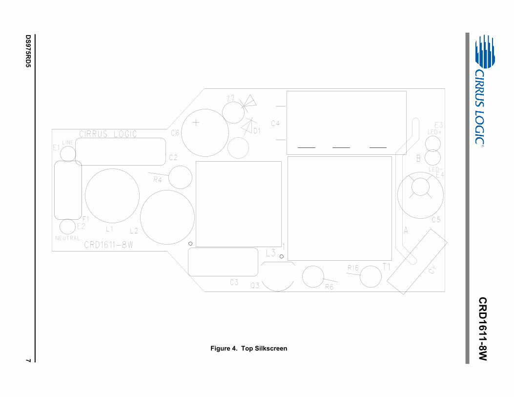
Figure 4. Top Silkscreen

CR
D1
611
-8W
8D
S9
75
RD
5 Figure 5. Bottom Silkscreen
Capacitor C12 added between D7 and R1

CR
D1
611
-8W
DS
975
RD
59
Figure 6. Top Routing

CR
D1
611
-8W
10
DS
975
RD
5 Figure 7. Bottom Routing
CRD1611-8W
DS975RD5 11
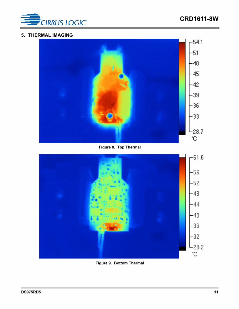
5. THERMAL IMAGING
Figure 8. Top Thermal
Figure 9. Bottom Thermal

CRD1611-8W
12 DS975RD5
6. DIMMER COMPATIBILITY - PAR 16 WITH CS1611 (220V - 240V)
Input Power 7.7W Dimmer Compatibility 972/1008 Efficiency 82.9%
Date 12/20/2011 Power Factor1,6 0.90
Vendor Cirrus Logic IEC-61000-3-2 Compliant (Y/N)3,6 Y
Input Voltage 230V EN55015 Compliant (Y/N) Y
Form Factor PAR 16 Nominal Input Power (W)1,6 7.7
Model # CRD1611-8W Maximum Input Power (W)2,6 8.8
IC CS1611 Output Voltage (V)1,4 11.8
Topology Boost/Flyback Output Current (mA)1,4 540
Isolation (Y/N) Y Output Current Ripple 120Hz (mA)1,5 0
Compatibility Spec. 1.0 Output Power (W)1,6 6.4
Efficiency (%) 82.9
Dimmer Type
Flicker Free
Steady-state
Monotonic
DimmingMax Iout (mA) Min Iout (mA)
Total# of Lamps # of Lamps # of Lamps # of Lamps
1 5 10 1 5 10 1 5 10 1 5 10
Berker - Leading/Trailing Edge Y Y N Y Y N 478 479 476 10 9 220 17
Bticino - Trailing Edge Y Y Y Y Y Y 270 241 212 9 9 10 21
Bull - Leading Edge Y Y Y Y Y Y 476 477 477 9 9 9 24
Busch - Leading Edge Y Y Y Y Y Y 476 477 476 9 9 9 24
Busch - Leading Edge Y Y Y Y Y Y 476 477 476 9 9 9 24
Busch - Trailing Edge Y Y Y Y Y Y 478 479 478 9 9 9 24
Busch - Trailing Edge Y Y Y Y Y Y 478 479 478 9 9 9 24
Chint New - Leading Edge Y Y Y Y Y Y 476 476 477 9 9 9 24
Chisen - Leading Edge Y Y Y Y Y Y 476 476 477 9 9 9 24
Chisen - Leading Edge Y N Y Y Y Y 476 476 477 9 9 9 19
Clipsal - Trailing Edge Y Y Y Y Y Y 476 476 476 9 9 9 24
Clipsal - Trailing Edge Y Y Y Y Y Y 476 476 475 9 9 9 24
Clipsal - Leading Edge Y Y Y Y Y Y 476 476 477 9 9 9 24
CLSEN - Leading Edge Y Y Y Y Y Y 476 476 476 9 8 9 24
Cshyh - Leading Edge Y Y Y Y Y Y 476 475 476 9 9 9 24
Dbang - Leading Edge Y Y Y Y Y Y 476 476 476 15 32 31 21
Elro - Twilight Sensor Y Y Y Y Y Y 475 475 474 0 0 0 24
Elro - Motion Sensor Y Y Y Y Y Y 475 476 474 0 0 0 24
Elro - Twilight Sensor Y Y Y Y Y Y 475 474 474 0 0 0 24
Futina - Leading Edge Y Y Y Y Y Y 476 476 477 9 10 10 24
Gangben - Leading Edge Y Y Y Y Y Y 500 500 500 10 10 10 24
Gira - Leading Edge Y Y Y Y Y Y 477 477 476 11 11 12 24
Jung - Leading/Trailing Edge Y Y Y Y Y Y 478 479 476 9 9 20 23

CRD1611-8W
DS975RD5 13
Notes: 1. Tested at nominal input voltage, nominal input frequency and without a dimmer after soaking for 15 minutes
2. Tested at nominal input voltage, nominal input frequency and with a dimmer after soaking for 15 minutes
3. Compliant with IEC 61000-3-2 Class C < 25W
4. Average
5. Peak-to-peak
6. Measured with Chroma 66202 Power Analyzer
Legrand - Leading/Trailing Edge Y Y Y Y Y Y 476 477 477 9 9 9 24
Leiben - Leading Edge Y Y Y Y Y Y 476 475 476 9 12 12 24
Lonon - Leading Edge Y Y Y Y Y Y 475 475 476 9 9 9 24
Lutron - Leading Edge Y Y Y Y Y Y 476 477 476 9 9 9 24
Lutron - Leading Edge Y Y Y Y Y Y 421 423 420 9 9 9 21
Merten - Leading Edge Y Y Y Y Y Y 476 477 476 9 9 9 24
Merten - Trailing Edge Y Y Y Y Y Y 432 417 400 9 9 9 21
MK - Leading Edge Y Y Y Y Y Y 475 475 476 9 9 9 24
Opus - Leading Edge Y Y Y Y Y Y 476 477 475 27 25 27 21
Opus - Leading Edge Y Y Y Y Y Y 476 477 475 9 9 9 24
OVE - Trailing Edge Y Y N Y Y N 478 470 0 9 10 - 16
Siemens - Leading Edge Y Y Y Y Y Y 476 475 476 9 9 9 24
Songri - Leading Edge Y Y Y Y Y Y 476 475 476 9 12 10 24
T&J - Leading Edge Y Y Y Y Y Y 476 475 476 9 12 9 24
T&J - Leading Edge Y Y Y Y Y Y 475 475 476 10 9 9 24
TCL - Leading Edge Y Y Y Y Y Y 476 475 476 9 9 9 24
TNC - Leading Edge Y Y Y Y Y Y 475 475 476 9 9 9 24
Wuyun - Leading Edge Y Y Y Y Y Y 476 477 474 9 9 9 24
Wuyun - Trailing Edge Y Y Y Y Y Y 478 478 476 9 9 9 24
Overall Total 972
Dimmer Type
Flicker Free
Steady-state
Monotonic
DimmingMax Iout (mA) Min Iout (mA)
Total# of Lamps # of Lamps # of Lamps # of Lamps
1 5 10 1 5 10 1 5 10 1 5 10

CRD1611-8W
14 DS975RD5
7. INDUCTOR CONSTRUCTION
The CRD1611-8W includes a critical conduction mode (CRM) boost converter that provides power factor correction
and dimmer compatibility with a constant output current, quasi-resonant flyback stage. The following sections de-
scribe the boost and flyback inductors installed on the CRD1611-8W.
7.1 Boost Inductor
The CS1611 uses an adaptive dimmer compatibility algorithm to control the boost inductor stage, which guarantees
dimmer compatibility operation plus enables flicker-free operation with leading-edge, trailing-edge, and digital dim-
mers (dimmers with an integrated power supply). The boost auxiliary winding is used for zero-current detection
(ZCD) and supplies power to the CS1611.
Figure 10. Boost Inductor Schematic
7.1.1 Electrical Specifications
Characteristics conditions:
� Operating temperature range: -25 °C to +120 °C (including coil heat)
Notes: 7. Measured across pins 1 and 2.
8. Measured across pins 5 and 4.
Parameter Condition Symbol Min Typ Max Unit
Boost Inductor
Primary Inductance (Note 7) fresonant=10kHz, 0.3V at 20°C LP 6.12 6.8 7.48 mH
Primary DC Resistance (Note 7) tDCR=20°C 12 15 18
Auxiliary DC Resistance (Note 8) tDCR=20°C 0.84 1.05 1.26
2
15
4
400T#37AWG(0.12mm)
22T#37 AWG(0.12 mm)
Primary
Auxillary
CRD1611-8W
DS975RD5 15
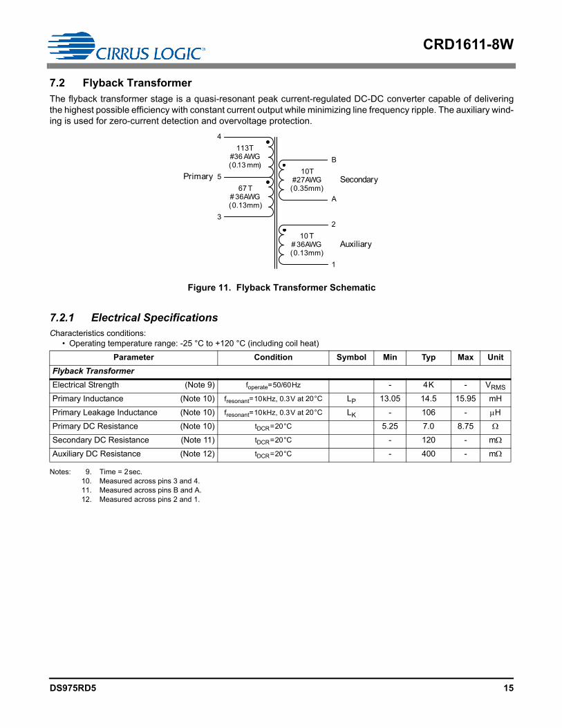
7.2 Flyback Transformer
The flyback transformer stage is a quasi-resonant peak current-regulated DC-DC converter capable of delivering
the highest possible efficiency with constant current output while minimizing line frequency ripple. The auxiliary wind-
ing is used for zero-current detection and overvoltage protection.
Figure 11. Flyback Transformer Schematic
7.2.1 Electrical Specifications
Characteristics conditions:
� Operating temperature range: -25 °C to +120 °C (including coil heat)
Notes: 9. Time = 2sec.
10. Measured across pins 3 and 4.
11. Measured across pins B and A.
12. Measured across pins 2 and 1.
Parameter Condition Symbol Min Typ Max Unit
Flyback Transformer
Electrical Strength (Note 9) foperate=50/60Hz - 4K - VRMS
Primary Inductance (Note 10) fresonant=10kHz, 0.3V at 20°C LP 13.05 14.5 15.95 mH
Primary Leakage Inductance (Note 10) fresonant=10kHz, 0.3V at 20°C LK - 106 - H
Primary DC Resistance (Note 10) tDCR=20°C 5.25 7.0 8.75
Secondary DC Resistance (Note 11) tDCR=20°C - 120 - m
Auxiliary DC Resistance (Note 12) tDCR=20°C - 400 - m
113T#36 AWG(0.13 mm)
67 T# 36AWG(0.13mm)
10 T# 36AWG(0.13mm)
Primary
4
5
3
1
Auxiliary
2
Secondary10T
#27AWG(0.35mm)
B
A

CRD1611-8W
16 DS975RD5
8. PERFORMANCE PLOTS
-0.1
0
0.1
0.2
0.3
0.4
0.5
0.6
20 40 60 80 100 120 140 160 180
Ou
tpu
t C
urr
en
t (A
)
Dim Angle (°)
Figure 12. Typical Output Current vs. Dim Angle
0
2
4
6
8
10
12
20 40 60 80 100 120 140 160 180
Inp
ut
Po
wer
(W)
Dim Angle (°)
Figure 13. Typical Input Power vs. Dim Angle

CRD1611-8W
DS975RD5 17
Figure 14. Output Current vs. Line Voltage
0.00
0.20
0.40
0.60
0.80
1.00
200 210 220 230 240 250 260
Ou
tpu
t C
urr
en
t (A
)
Line Voltage (V)
50
60
70
80
90
200 210 220 230 240 250 260
Eff
icie
nc
y (
%)
Vin (VAC)
Figure 15. Typical Efficiency vs. Line Voltage

CRD1611-8W
18 DS975RD5
Figure 16. Power Factor vs. Line Voltage, 207VAC to 253VAC
0.60
0.70
0.80
0.90
1.00
200 210 220 230 240 250 260
Po
wer
Fa
cto
r
Vin (VAC)

CRD1611-8W
DS975RD5 19
Figure 17. No-dimmer Mode, Startup 230VAC
Figure 18. No-dimmer Mode, Steady-state, 230VAC

CRD1611-8W
20 DS975RD5
Figure 19. Boost FET, Q2, Waveform
Figure 20. Flyback FET, Q4, Waveform

CRD1611-8W
DS975RD5 21
Figure 21. ILED at Maximum Dim Angle, Turn-on Waveforms
Figure 22. ILED at Medium Dim Angle, Turn-on Waveforms

CRD1611-8W
22 DS975RD5
Figure 23. ILED at Minimum Dim Angle, Turn-on Waveforms

CRD1611-8W
DS975RD5 23
9. CONDUCTED EMI
Device Under Test: CRD1611-8W-Z Operating Conditions: NOMNIAL
Test Specification: IEC 61000-3-2 Operator Name: JDW & JCM
Scan Settings (1 Range)
Final Measurement
Detectors: QP, AV Peaks: 25 Meas Time: 1s Acc. Margin: 6dB
Final Measurement Results
Frequencies Receiver Settings
Start Stop Step Res BW M-Time Atten Preamp
150kHz 30MHz 4.5kHz 9kHz (6dB) 10ms Auto Off
TraceFrequency
(MHz)
Level
(dBV)
Limit
(dBV)
Delta Limit
(dB)
Delta Ref
(dB)Comment
1QP 0.15 62.42 66.00 -3.58 N/on
2AV 0.15 51.27 56.00 -4.73 N/on
1QP 0.546 47.18 56.00 -8.82 N/on
* = Limit Exceeded
1 MHz 10 MHz150 kHz 30 MHz
10.0
20.0
30.0
40.0
50.0
60.0
70.0
0.0
80.0
dB V
Limits55022MQP55022MAV
TransducerENV216
TracesPK+AV
Figure 24. Conducted EMI
CRD1611-8W
24 DS975RD5
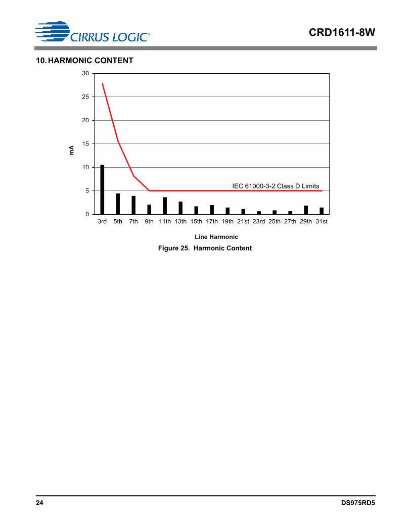
10.HARMONIC CONTENT
0
5
10
15
20
25
30
3rd 5th 7th 9th 11th 13th 15th 17th 19th 21st 23rd 25th 27th 29th 31st
mA
Line Harmonic
IEC 61000-3-2 Class D Limits
Figure 25. Harmonic Content

CRD1611-8W
DS975RD5 25
11.REVISION HISTORY
Revision Date Changes
RD1 DEC 2011 Initial release
RD2 JAN 2012 Content change to BOM, schematic, and bottom silkscreen
RD3 FEB 2012 Content change to features
RD4 MAY 2012 Corrected a typographical error
RD5 FEB 2013 Corrected typographical errors