cranfield university f mortel cranfield …f1-forecast.com/pdf/f1-files/cranfield team f1 -...
TRANSCRIPT
CRANFIELD UNIVERSITY
F MORTEL
CRANFIELD TEAM F1:
THE FRONT WING
SCHOOL OF ENGINEERING
CRANFIELD COLLEGE OF AERONAUTICS
MSc THESIS
CRANFIELD UNIVERSITY
SCHOOL OF ENGINEERING
CRANFIELD COLLEGE OF AERONAUTICS
MSc THESIS
Academic Year 2002-2003
F MORTEL
Cranfield Team F1: The front wing
Supervisor: P A RUBINI
September 2003
This thesis is submitted in partial fulfilment of the requirements for the degree of Master of Science
© Cranfield University 2003. All rights reserved. No part of this publication may be reproduced without the written permission of the copyright owner.
Florent MORTEL iii Cranfield Team F1: The Front Wing
ABSTRACT
Cranfield Formula 1 Team is a group design project composed of five students,
each of them being responsible for the design of one part of the vehicle. The
present thesis deals with the front wing design.
According to the time allowed to do the thesis and to learn the relevant
software to use, three models were built: one is quite simple and is the basis of
the two others. The aim was to design these three models using CAD (Catia V5,
a product from Dassault Systems), to build their meshes using Gridgen (a
product from Pointwise), to simulate the flow with Fluent 6.1 and finally to
visualise it thanks to Fieldview 9.
The main aims of the different models are to deflect the flow from the wheels to
reduce the drag created by the tyres and to create enough downforce taking
care to match the FIA Formula 1 technical regulation. The design focuses on the
endplates to fulfil these objectives.
Having done the CFD parts, the flow pattern was studied and the efficiencies of
the different devices designed were assessed. It appears that the behaviour of
the flow was greatly influenced by the front wheels (which were simulated with
the front wing) as expected and therefore that the design has to take account
of the environment of the front wing. The endplates demonstrate their utilities
as deflectors that are able to suck the flow inboard the wheels. They also show
that they can be additional downforce productive devices. The loads created
there are not huge but are honest compared to the surface used and to the fact
the design tested has been made without optimisation.
Finally, from the results of the simulation and the flow pattern obtained, many
ideas come out to improve the efficiency of the front wing.

Florent MORTEL iv Cranfield Team F1: The Front Wing
ACKNOWLEDGEMENTS
Dr Philip RUBINI
for his CFD advices
Jean-Marie “James” CAVET
for teaching me Gridgen
All my friends from Cranfield University for being who they are:
Audrey, Carine, Caro, Fabie (our fairy), Sophie, Véro,
Charlie, Florent (the tall but smaller one), James, Jérôme,
Markus, Nico, Pierre (for the breaks…), Robin, Seb and Steph.
Florent MORTEL v Cranfield Team F1: The Front Wing
LIST OF CONTENTS
INTRODUCTION ......................................................................................1
I. LITERATURE REVIEW ............................................................................2
1. THE FRONT WING..............................................................................2 2. AIMS AND OBJECTIVES ......................................................................2 3. OVERVIEW OF THE PAST FRONT WING DEVICES ....................................4 4. DESCRIPTION OF THE FLOW AROUND THE FRONT WING .......................10
4.1 Flow over the wing span ..............................................................10 4.2 Flow at the tips...........................................................................11
5. MATCHING THE 2003 FIA FORMULA ONE TECHNICAL REGULATION .........12 CONCLUSION .....................................................................................14
II. MODELS CREATION ...........................................................................15
1. THE DESIGN ...................................................................................15 1.1 The basic Model..........................................................................15 1.2 First Model.................................................................................18 1.3 Second Model.............................................................................19
2. EXPECTED FLOW PATTERN................................................................22 2.1 The multi-element airfoil..............................................................22 2.2 Vertical airfoils ...........................................................................22 2.3 Flow over wheels / Horizontal flat plates ........................................22 2.4 Inclined flat plates ......................................................................24
III. SIMULATION ...................................................................................26
1. MODELLING ......................................................................................26 1.1 Models ......................................................................................26 1.2 Wheel .......................................................................................26
2. GRID GENERATION..............................................................................27 2.1 The boundary layer .....................................................................27 2.2 Building the grid .........................................................................28
3. CFD SIMULATION ...............................................................................30 2.1 The solver .................................................................................30 2.2 The boundary conditions ..............................................................30
Florent MORTEL vi Cranfield Team F1: The Front Wing
IV. ANALYSIS........................................................................................33
1. FRONT WING PERFORMANCE.............................................................33 2. OBSERVED FLOW PATTERN...............................................................35
2.1 The multi-element airfoil..............................................................35 2.2 Vertical airfoils ...........................................................................36 2.3 Flow over wheels / Horizontal flat plates ........................................37 2.4 Inclined flat plates ......................................................................38
3. IMPROVEMENTS TO BE CARRIED OUT.................................................39 3.1 The multi-element airfoil..............................................................39 3.2 Vertical airfoils ...........................................................................39 3.3 Flow over wheels / Horizontal flat plates ........................................40 3.4 Inclined flat plates ......................................................................41
CONCLUSION........................................................................................44
BIBLIOGRAPHY .....................................................................................46
REFERENCES ........................................................................................47
Florent MORTEL vii Cranfield Team F1: The Front Wing
LIST OF FIGURES
Fig. 1: Lotus 49B (1968) [1] .......................................................................4 Fig. 2: Wing failure in 1969.......................................................................5 Fig. 3: McLaren M23-5 (1974) [1] ...............................................................5 Fig. 4: Ferrari 312 T2 (1975) ....................................................................6 Fig. 5: Single element Vs multi-element airfoil[1] ..........................................6 Fig. 6: Ferrari 640 (1989).........................................................................7 Fig. 7: Tyrrell 019 (1990) .........................................................................7 Fig. 8: Benetton B191 (1991)....................................................................8 Fig. 9: McLaren MP4/8 (1993)[3] ................................................................8 Fig. 10: Minardi M195 (1995)[3] .................................................................9 Fig. 11: McLaren MP4/17 (2002) [3] ..........................................................10 Fig. 12: Ferrari F2002 (2002) [3] ..............................................................11 Fig. 13: Jaguar R3 (2002)[6]....................................................................11 Fig. 14: The curved design at the centre of the span ..................................16 Fig. 15: The Basic Model.........................................................................17 Fig. 16: The first Model ..........................................................................18 Fig. 17: The first Model endplate .............................................................19 Fig. 18: The second Model ......................................................................20 Fig. 19: The second Model endplate .........................................................21
Fig. 20: Creating a vortex using the multi-element airfoil suction..................42
Fig. 21: FIA F1 technical regulation requirements......................................... I Fig. 22: Model 2 mesh............................................................................. II Fig. 23: Model 2 mesh along the plane at 0.4m from the leading edge ........... II Fig. 24: Evidence of the endplates efficiency with velocity contours ..............III Fig. 25: Venturi effect near the centre line (Basic model) ............................ IV Fig. 26: Flow around the two-element airfoil.............................................. IV Fig. 27: Pressure distribution at 18cm from the leading edge....................... IV Fig. 28: Pressure distribution at 5 cm from the centre line............................ V Fig. 29: Pressure distribution (including the isobars) around the two-element
airfoil .............................................................................................. V Fig. 30: The first airfoil section feeding the second one ............................... VI
Florent MORTEL viii Cranfield Team F1: The Front Wing
Fig. 31: Top and bottom view showing the pressure distribution on the multi-
element airfoil ................................................................................. VI Fig. 32: Bottom and top view of the front wing with the surface flows colored by
static pressure ................................................................................ VII Fig. 33: Velocity vectors showing the vortex due to the vertical airfoil shape at
20cm from the leading edge (Basic Model / SA)..................................VIII Fig. 34: Velocity vectors showing the flow induced by the suction from the
vertical airfoil (Basic Model / SA) ........................................................ IX Fig. 35: Velocity vectors showing the secondary vortex on Model 1 at 33 cms
from the leading edge........................................................................ X Fig. 36: Pressure distribution from the front and behind views ..................... XI Fig. 37: Pressure distribution at z=0.25m (Model 2) ................................... XI Fig. 38: Evidence of the rotating flow around the wheel ............................. XII Fig. 39: Pressure distribution on wheel surface ......................................... XII Fig. 40: Pressure distribution on wheel surface with isobars........................ XII Fig. 41: Bottom view from Model 1 ........................................................XIII Fig. 42: Pressure distribution around the small NACA 68005 (Model 1)........XIII Fig. 43: Low Pressure due to the secondary vortex (1st Model) ..................XIII Fig. 44: Flow at the trailing edge of the vertical airfoil (Basic model z=0.287m)
................................................................................................... XIV Fig. 45: Upper horizontal flat plate disrupting the flow (Model 2, z=0.287m) XIV Fig. 46: Vortex created by the inclined flat plate (2nd Model).......................XV Fig. 47: Vortex axis ...............................................................................XV Fig. 48: Velocity vectors showing the vortices at 35 cm from the leading edge
(2nd Model) .................................................................................. XVI Fig. 49: Side view showing the low pressure area due to the vortex........... XVII (Model 2) .......................................................................................... XVII Fig. 50: Bottom view of the front wing showing the low pressure area due to
the vortex (Model 2)...................................................................... XVII Fig. 51: Flow rounding the upper tip of the vertical airfoil (Model 2)........... XVII Fig. 52: Pressure distribution along the chord of the inclined flat plate (distance
are measured from the leading edge).............................................. XVIII
Aerospace Dynamics Introduction
Florent MORTEL 1 Cranfield Team F1: The Front Wing
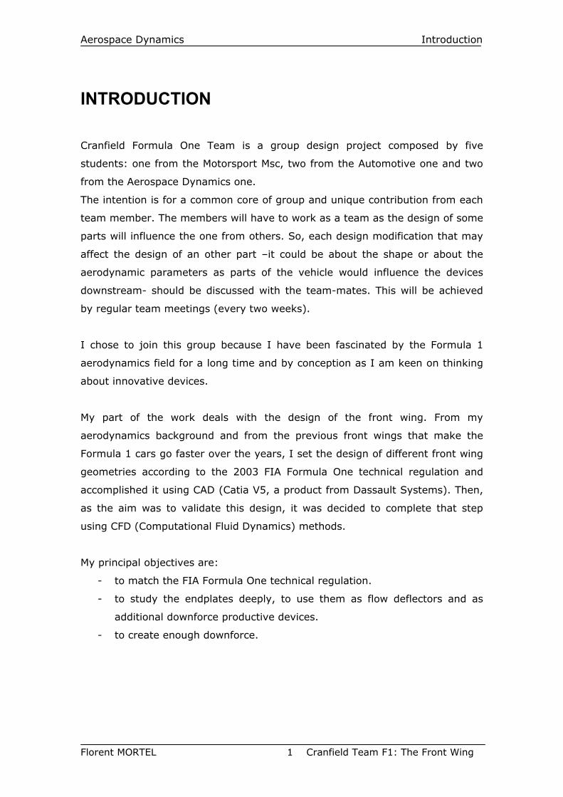
INTRODUCTION
Cranfield Formula One Team is a group design project composed by five
students: one from the Motorsport Msc, two from the Automotive one and two
from the Aerospace Dynamics one.
The intention is for a common core of group and unique contribution from each
team member. The members will have to work as a team as the design of some
parts will influence the one from others. So, each design modification that may
affect the design of an other part –it could be about the shape or about the
aerodynamic parameters as parts of the vehicle would influence the devices
downstream- should be discussed with the team-mates. This will be achieved
by regular team meetings (every two weeks).
I chose to join this group because I have been fascinated by the Formula 1
aerodynamics field for a long time and by conception as I am keen on thinking
about innovative devices.
My part of the work deals with the design of the front wing. From my
aerodynamics background and from the previous front wings that make the
Formula 1 cars go faster over the years, I set the design of different front wing
geometries according to the 2003 FIA Formula One technical regulation and
accomplished it using CAD (Catia V5, a product from Dassault Systems). Then,
as the aim was to validate this design, it was decided to complete that step
using CFD (Computational Fluid Dynamics) methods.
My principal objectives are:
- to match the FIA Formula One technical regulation.
- to study the endplates deeply, to use them as flow deflectors and as
additional downforce productive devices.
- to create enough downforce.
Aerospace Dynamics Literature Review
Florent MORTEL 2 Cranfield Team F1: The Front Wing
I. LITERATURE REVIEW This Literature review is based on the readings made during the thesis but most
of the information provided comes from the readings I have made since 1991
as I have been passionate by Formula 1 since this time. In this way, some
pieces of information are difficult to attribute or reference.
Some of the following front wing improvements quoted have been found too
just by looking at the cars through the history in museums [1], books (as
Ref.[2]) or magazines [3] and by seeing how they have evolved.
1. THE FRONT WING The front wing is usually the first part designed by teams. Failing designing an
efficient front wing may disrupt the whole aerodynamics of a Formula 1 car.
Indeed the balance of the car is determined by the load on the front wing as
the one on the rear wing is rarely modified on the track, the choice of the latter
being determined by the track simulator before coming to the circuit. So the
load on the front wing is required to be easily modified.
Nowadays the front wing is a two or three-element airfoil which is usually not
anymore straight along its span. The main flap is usually a rectangular
planform whereas the aft one could adopt a lot of different shape due to the
flow constraints downstream. Then a Gurney flap may be fixed at the aft flap
trailing-edge to gain some extra downforce. Finally, since the FIA Formula 1
technical regulation has constraint the teams to reduce the front track width of
the cars, wing tips have become very complex due to the wheel-wing tip flow
interaction.
2. AIMS AND OBJECTIVES Formula One teams spent a lot of time and money designing the shape of their
cars because of the importance of aerodynamics. Today the way to design a
Formula One front wing is to try several features using CAD and CFD methods,
to keep the ones that match the performance requirements for a specified track
and then to evaluate the efficiency of the best ones in wind tunnels, the latter
working 24 hours a day.
Aerospace Dynamics Literature Review
Florent MORTEL 3 Cranfield Team F1: The Front Wing
The front wing appeared in Formula One in 1968. It remains quite simple
features with single rectangular airfoil with flat vertical endplates until 1990
when the front wing development started speeding up. This trend has become
impressive since the middle of the nineties and especially since 1998 with the
new generation of front wing tips.
The purpose of this thesis is to design the front wing of a Formula One car
matching the 2003 FIA regulation.
A Formula One car can create downforce up to 1700 kg (2.8 times the mass of
the car) on a low speed sinuous track like Monaco. The front wing contributes
to generate 650kg on such a track at the highest speed the car can perform.
Then the aim of the front wing is to drive the air from its wing tips to the inside
of the front wheels so that the perturbation caused by the latter may be
reduced. This is done because the regulation allows building a front wing larger
than the front track width minus the two tyres width.
The design has been done by thinking up to a design made from scratch and
that may be innovative. This will be designed using CAD software. Then the
model will be meshed and exported to CFD software that will calculate the flow
characteristics around the front wing. Finally the results will be displayed using
flow visualisation software.
So the aim of this thesis is to create a front wing:
- that may generate a load of around 600 kg at 330 km/h.
- that may be able to deflect as air as possible from the wing tip to the
inside of the front wheels.
- to choose two suitable airfoil sections for the main wings.
Aerospace Dynamics Literature Review
Florent MORTEL 4 Cranfield Team F1: The Front Wing
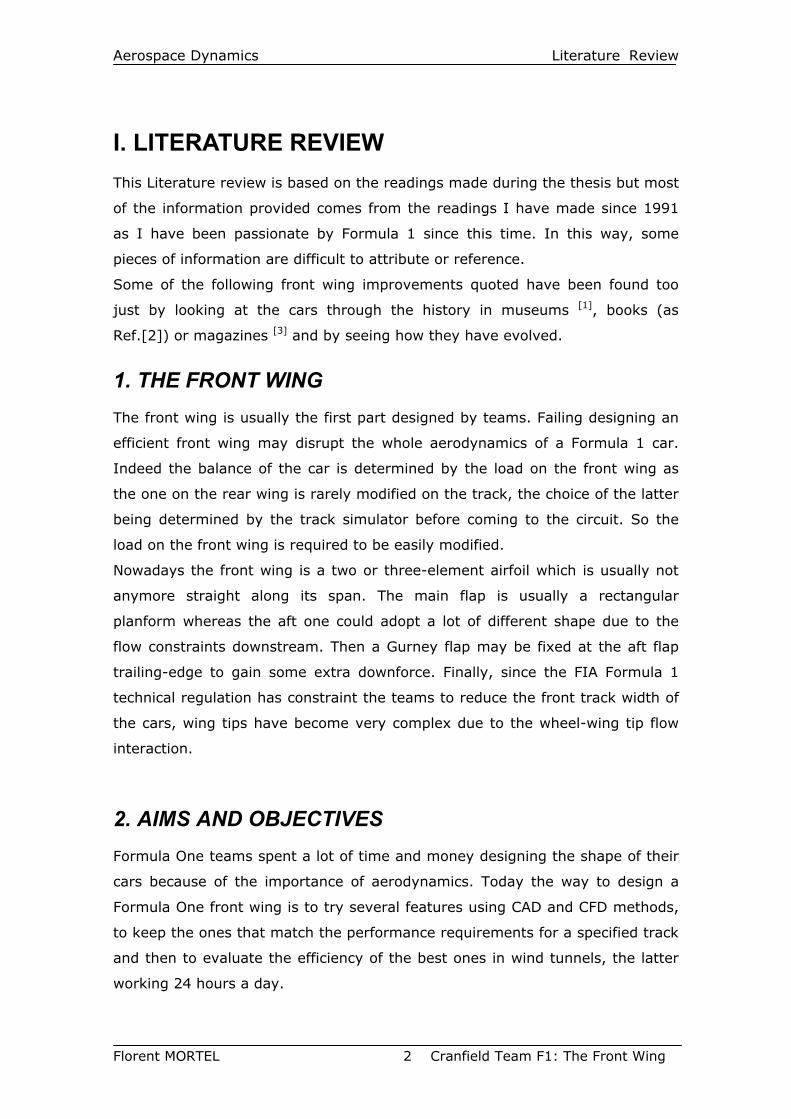
3. OVERVIEW OF THE PAST FRONT WING DEVICES Front wings appeared in Formula One on the Lotus 49B at the Monaco Grand
prix on the 25th of May 1968.
However, the first inverted wing to be used to create downforce in motorsport
was the one installed on the Chaparall 2E in 1966 [4].
Many Formula One constructors began to do the same thing and many wings
flourished on the Formula 1 circus. The wings were fixed on the wheel hubs of
the car to transfer the load directly to the wheels. This allows avoiding
stiffening the springs of the suspension system that might create instability on
undulating tracks. However the wings struts were not enough resistant and
they sometimes broke.
Fig. 1: Lotus 49B (1968) [1]
The CSI (Comité Sportif International) was totally beyond the team’s
improvements. So it did not expect the emergence of the inverted wings.
Moreover the teams went ahead by permitting the pilot to modify the incidence
of the wings thanks to a pedal whether the car was in a corner or in a straight
line.
But in 1969, the CSI modified the regulation:
- by prohibiting the mobile parts.
Aerospace Dynamics Literature Review
Florent MORTEL 5 Cranfield Team F1: The Front Wing
- by prohibiting the fixation of the wings struts on the suspension or wheels
hubs.
- by limiting the wings width and the chassis height to one metre.
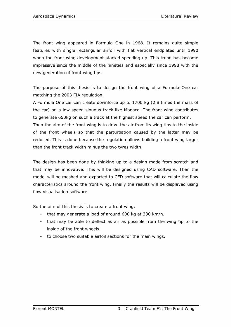
These decisions were taken for safety reasons as many wings struts failures
occur as during the terrible 1969 spanish grand prix with the horrendous crash
of the Lotus of Jochen Rindt and Graham Hill.
The teams then kept the same philosophy to design their front wing: a
rectangular planform shape with endplates varying in shape and size as most of
the aerodynamics improvements dealt with the underbody of the Formula One
car.
Fig. 2: Wing failure in 1969
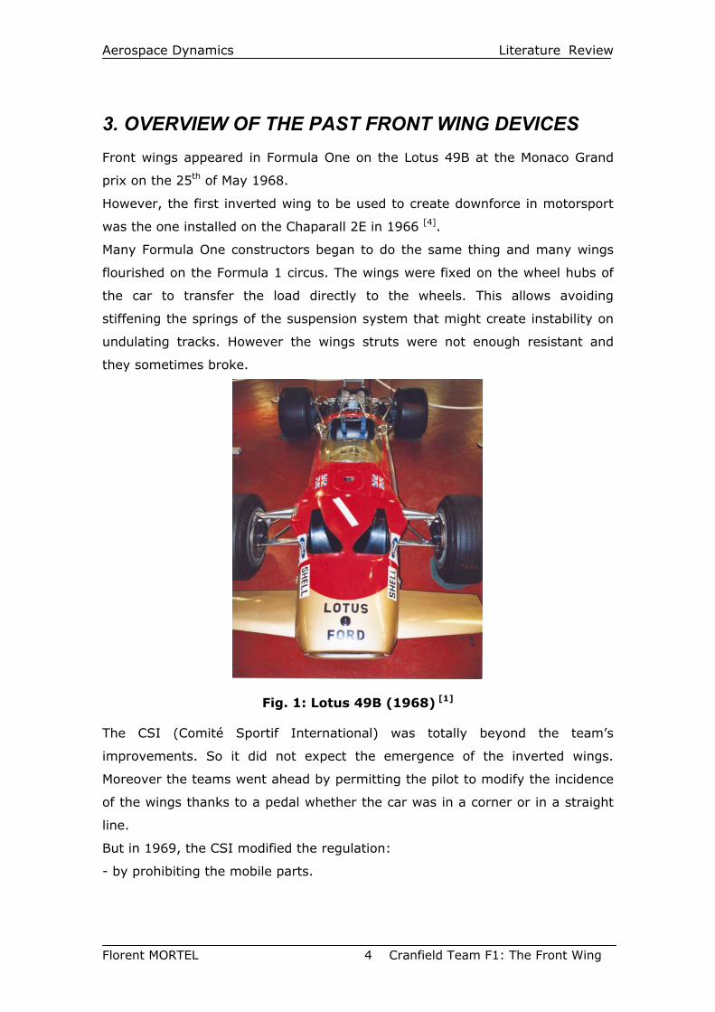
In 1971, a new improvement appeared[5]. Bobby Unser was fed up with the
Dan Gurney’s car which was not quick enough. So he challenged Dan Gurney to
come up with an improvement. The latter tried to fit a small spoiler at the
trailing edge of the rear wing. In 45 minutes, the first Gurney flap was born and
Bobby Unser tried it directly on the track. He was not faster but was surprised
of the car was understeering. This was due to the new high-lift device: the
Gurney flap.
Fig. 3: McLaren M23-5 (1974) [1]
This device is a flat trailing edge flap perpendicular to the chord and that is not
longer that 5% of the chord (some new ones are not flat but are serrated). It
Aerospace Dynamics Literature Review
Florent MORTEL 6 Cranfield Team F1: The Front Wing
has been usually used at the front wing trailing edge to improve the load at the
aft part of the second element (as if it is fixed at the first element, the flow
would be disrupted and would not feed the second element’s lower surface as
well as it should).
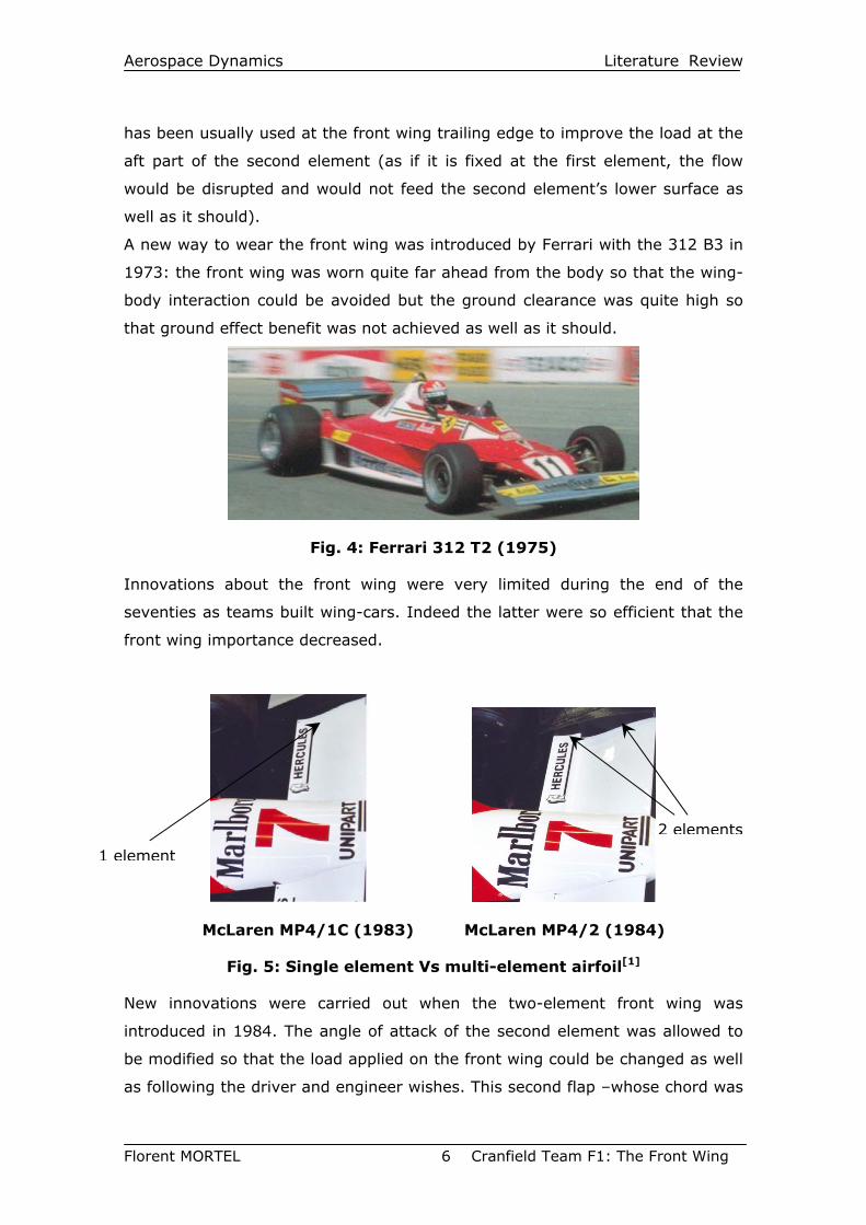
A new way to wear the front wing was introduced by Ferrari with the 312 B3 in
1973: the front wing was worn quite far ahead from the body so that the wing-
body interaction could be avoided but the ground clearance was quite high so
that ground effect benefit was not achieved as well as it should.
Fig. 4: Ferrari 312 T2 (1975)
Innovations about the front wing were very limited during the end of the
seventies as teams built wing-cars. Indeed the latter were so efficient that the
front wing importance decreased.
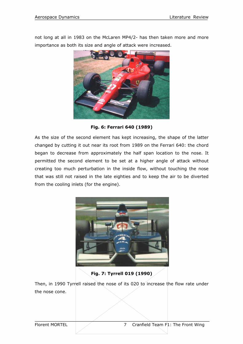
McLaren MP4/1C (1983) McLaren MP4/2 (1984)
Fig. 5: Single element Vs multi-element airfoil[1]
New innovations were carried out when the two-element front wing was
introduced in 1984. The angle of attack of the second element was allowed to
be modified so that the load applied on the front wing could be changed as well
as following the driver and engineer wishes. This second flap –whose chord was
2 elements
1 element
Aerospace Dynamics Literature Review
Florent MORTEL 7 Cranfield Team F1: The Front Wing
not long at all in 1983 on the McLaren MP4/2- has then taken more and more
importance as both its size and angle of attack were increased.
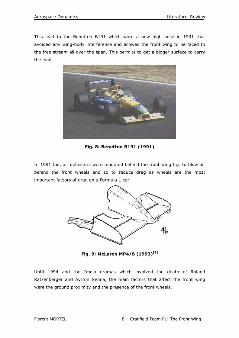
Fig. 6: Ferrari 640 (1989)
As the size of the second element has kept increasing, the shape of the latter
changed by cutting it out near its root from 1989 on the Ferrari 640: the chord
began to decrease from approximately the half span location to the nose. It
permitted the second element to be set at a higher angle of attack without
creating too much perturbation in the inside flow, without touching the nose
that was still not raised in the late eighties and to keep the air to be diverted
from the cooling inlets (for the engine).
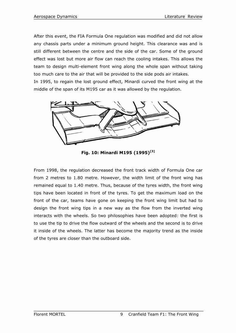
Fig. 7: Tyrrell 019 (1990)
Then, in 1990 Tyrrell raised the nose of its 020 to increase the flow rate under
the nose cone.
Aerospace Dynamics Literature Review
Florent MORTEL 8 Cranfield Team F1: The Front Wing
This lead to the Benetton B191 which wore a new high nose in 1991 that
avoided any wing-body interference and allowed the front wing to be faced to
the free stream all over the span. This permits to get a bigger surface to carry
the load.
Fig. 8: Benetton B191 (1991)
In 1991 too, air deflectors were mounted behind the front wing tips to blow air
behind the front wheels and so to reduce drag as wheels are the most
important factors of drag on a Formula 1 car.
Fig. 9: McLaren MP4/8 (1993)[3]
Until 1994 and the Imola dramas which involved the death of Roland
Ratzenberger and Ayrton Senna, the main factors that affect the front wing
were the ground proximity and the presence of the front wheels.
Aerospace Dynamics Literature Review
Florent MORTEL 9 Cranfield Team F1: The Front Wing
After this event, the FIA Formula One regulation was modified and did not allow
any chassis parts under a minimum ground height. This clearance was and is
still different between the centre and the side of the car. Some of the ground
effect was lost but more air flow can reach the cooling intakes. This allows the
team to design multi-element front wing along the whole span without taking
too much care to the air that will be provided to the side pods air intakes.
In 1995, to regain the lost ground effect, Minardi curved the front wing at the
middle of the span of its M195 car as it was allowed by the regulation.
Fig. 10: Minardi M195 (1995)[3]
From 1998, the regulation decreased the front track width of Formula One car
from 2 metres to 1.80 metre. However, the width limit of the front wing has
remained equal to 1.40 metre. Thus, because of the tyres width, the front wing
tips have been located in front of the tyres. To get the maximum load on the
front of the car, teams have gone on keeping the front wing limit but had to
design the front wing tips in a new way as the flow from the inverted wing
interacts with the wheels. So two philosophies have been adopted: the first is
to use the tip to drive the flow outward of the wheels and the second is to drive
it inside of the wheels. The latter has become the majority trend as the inside
of the tyres are closer than the outboard side.
Aerospace Dynamics Literature Review
Florent MORTEL 10 Cranfield Team F1: The Front Wing
4. DESCRIPTION OF THE FLOW AROUND THE FRONT WING
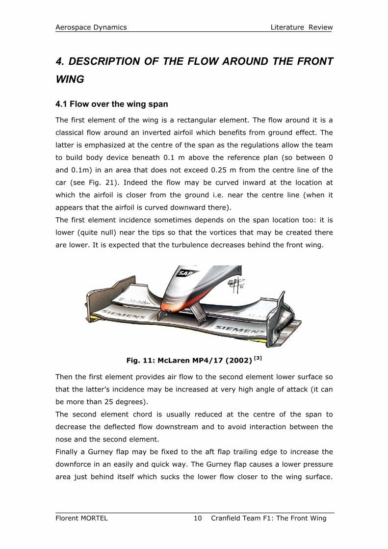
4.1 Flow over the wing span
The first element of the wing is a rectangular element. The flow around it is a
classical flow around an inverted airfoil which benefits from ground effect. The
latter is emphasized at the centre of the span as the regulations allow the team
to build body device beneath 0.1 m above the reference plan (so between 0
and 0.1m) in an area that does not exceed 0.25 m from the centre line of the
car (see Fig. 21). Indeed the flow may be curved inward at the location at
which the airfoil is closer from the ground i.e. near the centre line (when it
appears that the airfoil is curved downward there).
The first element incidence sometimes depends on the span location too: it is
lower (quite null) near the tips so that the vortices that may be created there
are lower. It is expected that the turbulence decreases behind the front wing.
Fig. 11: McLaren MP4/17 (2002) [3]
Then the first element provides air flow to the second element lower surface so
that the latter’s incidence may be increased at very high angle of attack (it can
be more than 25 degrees).
The second element chord is usually reduced at the centre of the span to
decrease the deflected flow downstream and to avoid interaction between the
nose and the second element.
Finally a Gurney flap may be fixed to the aft flap trailing edge to increase the
downforce in an easily and quick way. The Gurney flap causes a lower pressure
area just behind itself which sucks the lower flow closer to the wing surface.
Aerospace Dynamics Literature Review
Florent MORTEL 11 Cranfield Team F1: The Front Wing
The Gurney causes some extra drag as well, but the wing can be run at a
higher angle of attack and so can produce more downforce.
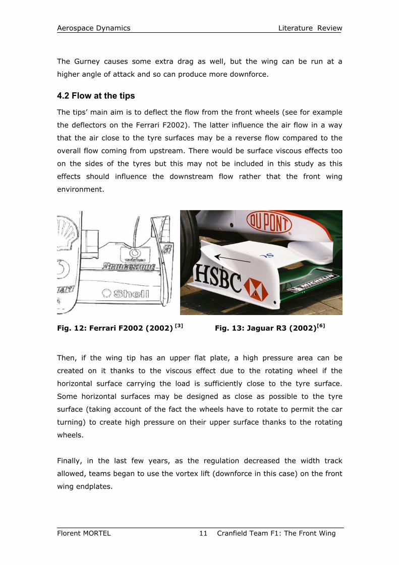
4.2 Flow at the tips
The tips’ main aim is to deflect the flow from the front wheels (see for example
the deflectors on the Ferrari F2002). The latter influence the air flow in a way
that the air close to the tyre surfaces may be a reverse flow compared to the
overall flow coming from upstream. There would be surface viscous effects too
on the sides of the tyres but this may not be included in this study as this
effects should influence the downstream flow rather that the front wing
environment.
Fig. 12: Ferrari F2002 (2002) [3] Fig. 13: Jaguar R3 (2002)[6]
Then, if the wing tip has an upper flat plate, a high pressure area can be
created on it thanks to the viscous effect due to the rotating wheel if the
horizontal surface carrying the load is sufficiently close to the tyre surface.
Some horizontal surfaces may be designed as close as possible to the tyre
surface (taking account of the fact the wheels have to rotate to permit the car
turning) to create high pressure on their upper surface thanks to the rotating
wheels.
Finally, in the last few years, as the regulation decreased the width track
allowed, teams began to use the vortex lift (downforce in this case) on the front
wing endplates.
Aerospace Dynamics Literature Review
Florent MORTEL 12 Cranfield Team F1: The Front Wing
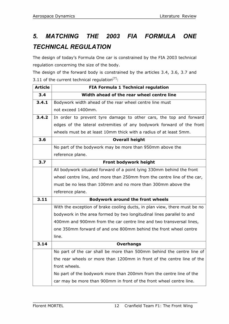
5. MATCHING THE 2003 FIA FORMULA ONE TECHNICAL REGULATION The design of today’s Formula One car is constrained by the FIA 2003 technical
regulation concerning the size of the body.
The design of the forward body is constrained by the articles 3.4, 3.6, 3.7 and
3.11 of the current technical regulation[7]:
Article FIA Formula 1 Technical regulation
3.4 Width ahead of the rear wheel centre line
3.4.1 Bodywork width ahead of the rear wheel centre line must
not exceed 1400mm.
3.4.2 In order to prevent tyre damage to other cars, the top and forward
edges of the lateral extremities of any bodywork forward of the front
wheels must be at least 10mm thick with a radius of at least 5mm.
3.6 Overall height
No part of the bodywork may be more than 950mm above the
reference plane.
3.7 Front bodywork height
All bodywork situated forward of a point lying 330mm behind the front
wheel centre line, and more than 250mm from the centre line of the car,
must be no less than 100mm and no more than 300mm above the
reference plane.
3.11 Bodywork around the front wheels
With the exception of brake cooling ducts, in plan view, there must be no
bodywork in the area formed by two longitudinal lines parallel to and
400mm and 900mm from the car centre line and two transversal lines,
one 350mm forward of and one 800mm behind the front wheel centre
line.
3.14 Overhangs
No part of the car shall be more than 500mm behind the centre line of
the rear wheels or more than 1200mm in front of the centre line of the
front wheels.
No part of the bodywork more than 200mm from the centre line of the
car may be more than 900mm in front of the front wheel centre line.
Aerospace Dynamics Literature Review
Florent MORTEL 13 Cranfield Team F1: The Front Wing
The design of the forward part of the car is also influenced by the front wheels
and the resulting flow around them.
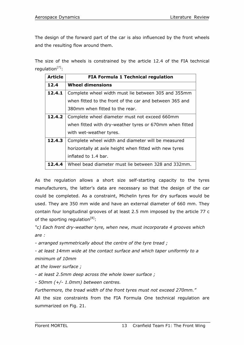
The size of the wheels is constrained by the article 12.4 of the FIA technical
regulation[7]:
Article FIA Formula 1 Technical regulation
12.4 Wheel dimensions
12.4.1 Complete wheel width must lie between 305 and 355mm
when fitted to the front of the car and between 365 and
380mm when fitted to the rear.
12.4.2 Complete wheel diameter must not exceed 660mm
when fitted with dry-weather tyres or 670mm when fitted
with wet-weather tyres.
12.4.3 Complete wheel width and diameter will be measured
horizontally at axle height when fitted with new tyres
inflated to 1.4 bar.
12.4.4 Wheel bead diameter must lie between 328 and 332mm.
As the regulation allows a short size self-starting capacity to the tyres
manufacturers, the latter’s data are necessary so that the design of the car
could be completed. As a constraint, Michelin tyres for dry surfaces would be
used. They are 350 mm wide and have an external diameter of 660 mm. They
contain four longitudinal grooves of at least 2.5 mm imposed by the article 77 c
of the sporting regulation[8]:
“c) Each front dry-weather tyre, when new, must incorporate 4 grooves which
are :
- arranged symmetrically about the centre of the tyre tread ;
- at least 14mm wide at the contact surface and which taper uniformly to a
minimum of 10mm
at the lower surface ;
- at least 2.5mm deep across the whole lower surface ;
- 50mm (+/- 1.0mm) between centres.
Furthermore, the tread width of the front tyres must not exceed 270mm.”
All the size constraints from the FIA Formula One technical regulation are
summarized on Fig. 21.
Aerospace Dynamics Literature Review
Florent MORTEL 14 Cranfield Team F1: The Front Wing
CONCLUSION Considering the history of the front wing, all the devices that have already been
tried and the environment of the front wing, a whole front wing including the
tips will be designed according to the FIA Formula One Regulations.
The history shows us the way to follow as the past is the prologue to the future.
So the designs implemented would be the results of the past front wings but
have to try to bring innovative devices. It would then be assessed using CFD
methods (mesh, flow parameters calculations, visualisation).
Aerospace Dynamics Models Creation
Florent MORTEL 15 Cranfield Team F1: The Front Wing
II. MODELS CREATION The models were designed from scratch. This study focuses on the way to
design the front wing and as the airfoils used for the horizontal multi-element
wing are not current ones, the expected load on the front wing –around 2500N
at 60 m/s- may not be reached even if the aim is to get as close to this amount
as possible.
1. THE DESIGN This part describes the different features contained by the different geometries
built. The reason for designing the models in the way they are and the
expected flow pattern around them are explained is the next section.
1.1 The basic Model
1.1.1 The multi-element airfoil
The basic element of a front wing is of course an airfoil. Nowadays, most of the
teams use two-element airfoils even if some begin to use three-element airfoils
for their front wing.
As I do not get any Formula One airfoil data, I used a GAW-1 airfoil for the first
element as it has been used in the early nineties, the second being an airfoil
section that have been used in an other motorsport area. The first element is
set with an incidence of -1.5 degrees whereas the second one is set at 16
degrees.
The GAW-1 airfoil is designed as a rectangular wing of constant chord -the
aspect ratio from the GAW-1 element being 5.4- whereas the second element
chord is variable: it is shortened as the location is closed from the centre of the
span. This is done to avoid any interaction with the nose witch dimensions are
not already known.
Then, as the FIA Formula One technical regulation allows to decrease the ride
height of any bodywork part at the centre of the span (until 25 cm from the
centre line) to the reference plane, the decision of curving the wings at this
location was taken to take advantage of the ground effect as much as possible.
It should be noted that the ride height is not decreased along the whole length
allowed by the regulation. This has been done to prevent a step in static
Aerospace Dynamics Models Creation
Florent MORTEL 16 Cranfield Team F1: The Front Wing
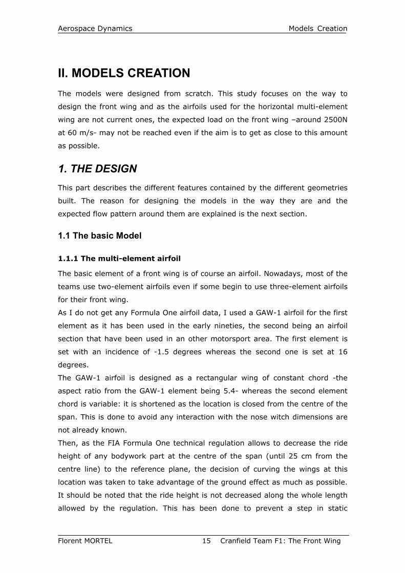
pressure at 25cm from the centre line and to permit the great depression at the
centre of the wing to influence the pressure distribution along the whole span.
Fig. 14: The curved design at the centre of the span
At the tips, it was desired that the first element should be mounted higher to
get a significant gap between its lower surface and the bottom of endplates. To
fulfil this condition, the two elements are sloped along their span from the
location at 25 cm from the centre line (at a height of 10 cm above the
reference plane) to the endplates (at a height of 13.86 cm above the reference
plane). This would prevent the air to round the tip as a great depression would
suck the flow below the wing.
1.1.2 The endplates
The endplates have to be settled, according to the regulation, between 10 cm
and 30 cm above the reference plane. This gap can be occupied by
aerodynamics devices to deflect the flow inboard the wheels and to create
additional downforce.
To deflect the flow, a thin vertical airfoil is introduced. It is referenced as NACA
68005 and is set with an incidence of 12 degrees.
It is a NACA 5-digit airfoil. The primary difference is the use of a different
camber line. In a 5-digit airfoil, 1.5 times the first digit is the design lift
coefficient in tenths, the second and third digits are one-half the distance from
the leading edge to the location of maximum camber in percent of the chord,
and the fourth and fifth digits are the thickness in percent of the chord.
Aerospace Dynamics Models Creation
Florent MORTEL 17 Cranfield Team F1: The Front Wing
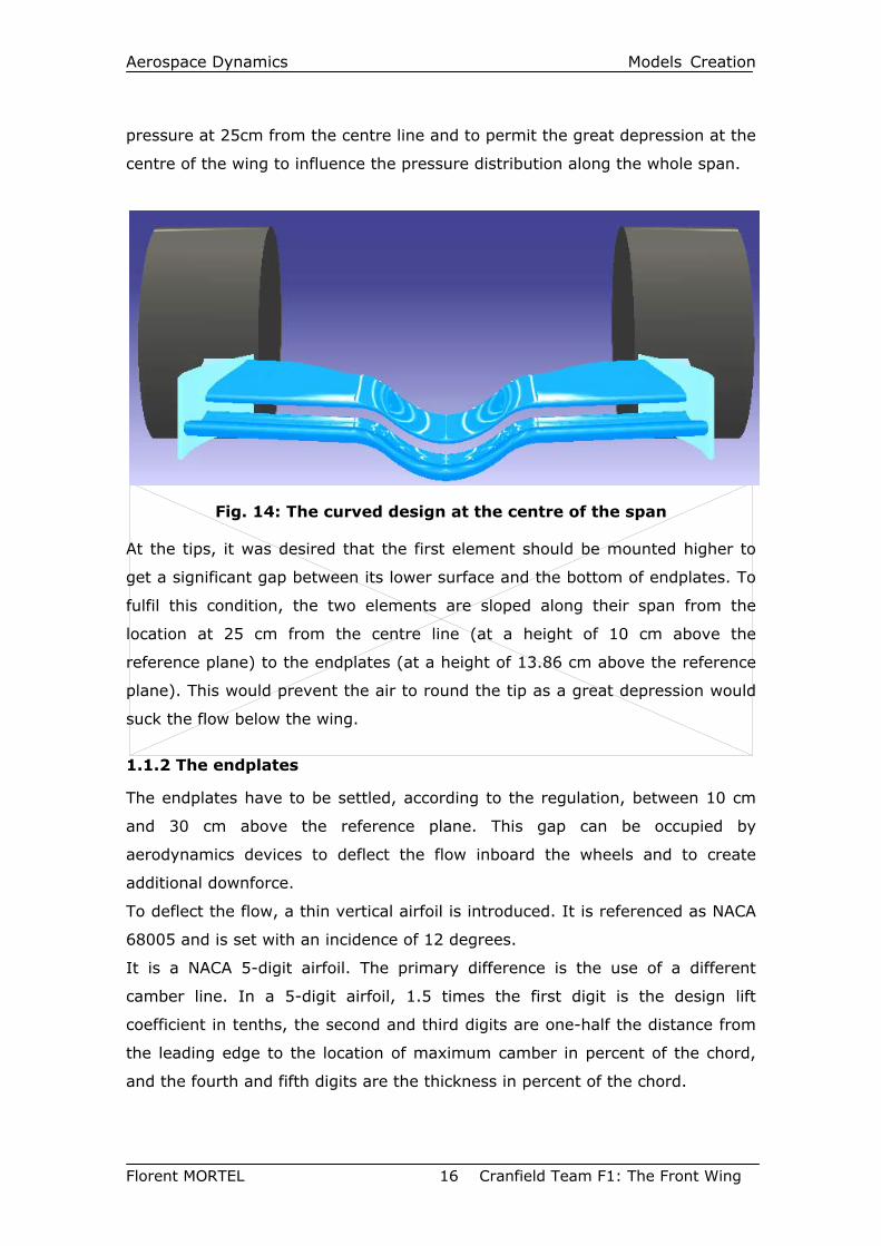
Fig. 15: The Basic Model
So here, the NACA 68005 has a design lift coefficient of 0.8, has the maximum
camber at 0.4c and is 5% thick. Additionally, the first three digits indicate the
mean line used. In this case, the mean line designation is 680.
The data of this section was created using the software “The NACA ordinate
generation program V4.5-F” created by D.Lednincer and simplified by JC
Etiemble.
This vertical airfoil is positioned so that the whole span allowed by the
regulation is used and so that its trailing edge reaches the location at 55 cm
from the centre line i.e. the inner face of the tyre. The flow inboard this vertical
airfoil at its leading edge would of course be deflected inboard. Then, it is
hoped that the flow should remain attached on the upper surface of the NACA
68005. It may be the case even if the stalling angle were reached as the air
would have to round the wheel and so it would feed the upper surface (the
outboard one) with enough air to prevent any separation.
This primary design sets a basic model of the front wing. Two models were born
from the latter so that their efficiency might be compared. Building a basic
geometry also permits to know the influence of the different part of the
different front wings.
Aerospace Dynamics Models Creation
Florent MORTEL 18 Cranfield Team F1: The Front Wing
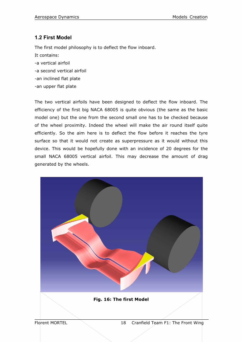
1.2 First Model
The first model philosophy is to deflect the flow inboard.
It contains:
-a vertical airfoil
-a second vertical airfoil
-an inclined flat plate
-an upper flat plate
The two vertical airfoils have been designed to deflect the flow inboard. The
efficiency of the first big NACA 68005 is quite obvious (the same as the basic
model one) but the one from the second small one has to be checked because
of the wheel proximity. Indeed the wheel will make the air round itself quite
efficiently. So the aim here is to deflect the flow before it reaches the tyre
surface so that it would not create as superpressure as it would without this
device. This would be hopefully done with an incidence of 20 degrees for the
small NACA 68005 vertical airfoil. This may decrease the amount of drag
generated by the wheels.
Fig. 16: The first Model
Aerospace Dynamics Models Creation
Florent MORTEL 19 Cranfield Team F1: The Front Wing
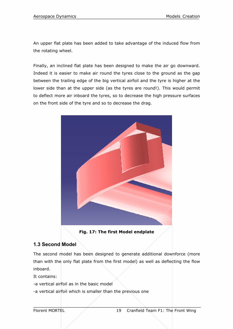
An upper flat plate has been added to take advantage of the induced flow from
the rotating wheel.
Finally, an inclined flat plate has been designed to make the air go downward.
Indeed it is easier to make air round the tyres close to the ground as the gap
between the trailing edge of the big vertical airfoil and the tyre is higher at the
lower side than at the upper side (as the tyres are round!). This would permit
to deflect more air inboard the tyres, so to decrease the high pressure surfaces
on the front side of the tyre and so to decrease the drag.
Fig. 17: The first Model endplate
1.3 Second Model
The second model has been designed to generate additional downforce (more
than with the only flat plate from the first model) as well as deflecting the flow
inboard.
It contains:
-a vertical airfoil as in the basic model
-a vertical airfoil which is smaller than the previous one
Aerospace Dynamics Models Creation
Florent MORTEL 20 Cranfield Team F1: The Front Wing
-a delta flat plate at 12° incidence
-an upper horizontal flat plate
-a lower horizontal flat plate
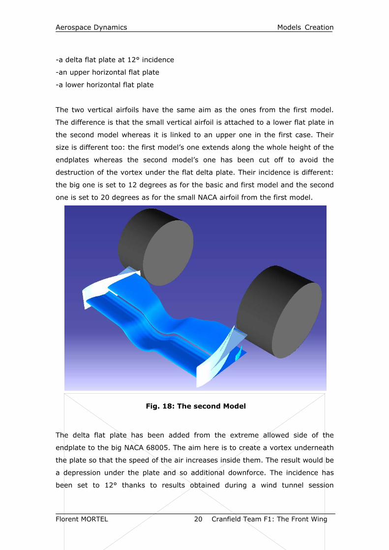
The two vertical airfoils have the same aim as the ones from the first model.
The difference is that the small vertical airfoil is attached to a lower flat plate in
the second model whereas it is linked to an upper one in the first case. Their
size is different too: the first model’s one extends along the whole height of the
endplates whereas the second model’s one has been cut off to avoid the
destruction of the vortex under the flat delta plate. Their incidence is different:
the big one is set to 12 degrees as for the basic and first model and the second
one is set to 20 degrees as for the small NACA airfoil from the first model.
Fig. 18: The second Model
The delta flat plate has been added from the extreme allowed side of the
endplate to the big NACA 68005. The aim here is to create a vortex underneath
the plate so that the speed of the air increases inside them. The result would be
a depression under the plate and so additional downforce. The incidence has
been set to 12° thanks to results obtained during a wind tunnel session
Aerospace Dynamics Models Creation
Florent MORTEL 21 Cranfield Team F1: The Front Wing
attended with a student of the course (It should be noted that the delta wing
used during these tests was not totally flat. So maybe this incidence should be
refined).
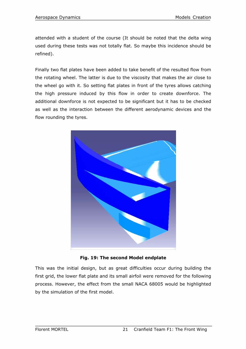
Finally two flat plates have been added to take benefit of the resulted flow from
the rotating wheel. The latter is due to the viscosity that makes the air close to
the wheel go with it. So setting flat plates in front of the tyres allows catching
the high pressure induced by this flow in order to create downforce. The
additional downforce is not expected to be significant but it has to be checked
as well as the interaction between the different aerodynamic devices and the
flow rounding the tyres.
Fig. 19: The second Model endplate
This was the initial design, but as great difficulties occur during building the
first grid, the lower flat plate and its small airfoil were removed for the following
process. However, the effect from the small NACA 68005 would be highlighted
by the simulation of the first model.
Aerospace Dynamics Models Creation
Florent MORTEL 22 Cranfield Team F1: The Front Wing
2. EXPECTED FLOW PATTERN
2.1 The multi-element airfoil
Because of the restrictions due to the FIA F1 technical regulation, the
downforce needed has to be obtained with a limited surface. So, to get the right
balance on the car, introducing a multi–element airfoil is required.
The first element sets a minimum amount of downforce and the second element
is a movable part which angle of attack may be changed. In this way, teams
are able to modify the balance of the car easily during testing sessions and
grand prix.
The second element is used to being set at an angle of attack between 10 and
25 degrees. Separation does not occur as the first element feeds the lower
surface of the second one with the air from its trailing edge.
No vortices are expected to be created with this two-element airfoil as it has
not been set in the design aims of the whole car. Indeed, if a vortex is created
there, it should be used downstream to create low pressure as the speed inside
the core of the vortex would be higher. However, it seems that a flow that
could be as clean as possible (without any vortex) should be expected. To avoid
any vortex, the first element was designed as a rectangular planform and the
modifications of the chord along the span were made smoothly for the second
element. Indeed, if corners had occur along the span of the second element to
decrease the chord, vortices would have been created.
2.2 Vertical airfoils
The aim is to get a thin and quite cambered airfoil which could be set at around
15 degrees without separation. The NACA 68005 is enough thin and is suitable
to deflect the flow quite well without being too cumbersome (which is important
because of the size restriction from the regulation).
2.3 Flow over wheels / Horizontal flat plates
The wheels are the devices that are responsible for the biggest production of
drag: around half the drag of the car. Therefore the aim is to deflect the flow
from the wheels so that the less air reaches the tyre surface.
Aerospace Dynamics Models Creation
Florent MORTEL 23 Cranfield Team F1: The Front Wing
Because of their shape and the fact that they are stuck to the ground, the
wheels create lift[9]. Considering an infinite wide stationary cylinder, the flow
pattern would be the following: the particles of air would be accelerated on the
upper surface and would not be able to go through the lower one as the
cylinder is assumed to be stuck to the ground. The flow would separate at
around 160 degrees from the stagnation point. This means that the flow
remains attached along a great distance and that the pressure coefficient
becomes more negative on the upper surface because of the higher speed
induced: in theory, the speed of air is doubled at 90 degrees from the
stagnation point on the upper surface. This results in additional lift as it is the
upper surface but it results too in additional drag as this negative pressure area
is mostly located behind the middle of the wheel.
Then, as the wheel rotates, the separation point goes forward. This destroys
the original lift generated by the wheel and the drag generated by low pressure
surface too. However drag is very high because of the separated flow behind
the wheel.
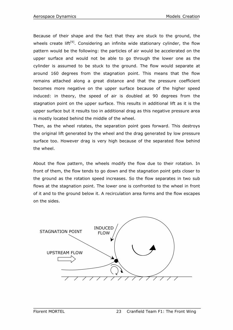
About the flow pattern, the wheels modify the flow due to their rotation. In
front of them, the flow tends to go down and the stagnation point gets closer to
the ground as the rotation speed increases. So the flow separates in two sub
flows at the stagnation point. The lower one is confronted to the wheel in front
of it and to the ground below it. A recirculation area forms and the flow escapes
on the sides.
UPSTREAM FLOW
INDUCED FLOW STAGNATION POINT
Aerospace Dynamics Models Creation
Florent MORTEL 24 Cranfield Team F1: The Front Wing
The aim is to take benefit of this induced flow by adding horizontal flat plates.
The more they are located close to the ground and the wheel, the more
additional downforce generated by the high pressure in this region. Downforce
is there created by the fact the plates in this region would be hit by the air
coming from the top and so, high pressure area would be created on their
upper side.
2.4 Inclined flat plates
Whereas airfoils aim is to maintain the flow attached to generate downforce,
the latter can be produced by making the flow separate. This is done by using
flat plates utilising the vortex lift.
The flow is expected to separate at the leading edge (or apex in our case)
which has to be very sharp. This phenomenon occurs at very high angles of
attack as the flow would remain attached if the plate is not enough sloped.
In our case, the plate is a delta-shaped wing with an external boundary parallel
to the main flow direction (view from the top) and with the internal edge stuck
to the main vertical airfoil surface. Of course, this plate has a negative angle of
attack to create a vortex under the plate.
In our case, the flow would separate along the edge of the plate and develops
on the lower surface. The layers of air would mix and form a free shear layer
that rolls down in a concentrated spiral vortex. Its thickness increases with the
distance to the apex.
This strong vortex induces high speed and low pressure upon the vortex core.
So the low pressure area is located under the flat plate and so downforce is
created. On a traverse section, the pressure reaches a minimum value at the
axis location of the primary vortex. Indeed, the primary vortex born from the
separation of the boundary layer at the side edge of the plate can induce a
secondary vortex.
Such a vortex (the primary one) can burst if the angle of attack is too high and
the burst point moves upstream by increasing it.
However the flat plate used on the second model of the front wing would be
short enough to prevent vortex bursting. But the vortex will certainly be
disrupted by the flow induced by the rotating wheel or by the superpressure in
front of the tyre.
Aerospace Dynamics Models Creation
Florent MORTEL 25 Cranfield Team F1: The Front Wing
The drag penalty of this kind of device is significant and is higher than the one
from an airfoil but it is not really important here as the vortex goes
downstream in the direction of the tyre and may be destroyed by the latter.
Anyway, the drag penalty from this device can not increase the drag
significantly as the tyre already fulfils this “mission”. So the location of this
sloped flat plate is particularly adapted.
Aerospace Dynamics Simulation
Florent MORTEL 26 Cranfield Team F1: The Front Wing
III. SIMULATION
1. Modelling
1.1 Models
The models have been done with Dassault Systems Catia Version 5. A basic
model with the two-element airfoil and the vertical airfoil as an endplate was
first tested as the geometries from the other designs were more complicated.
Then the first and the second model were designed. However, the second
model was truncated as the edges provided by Catia were not suitable for
Gridgen. This problem highlights the huge importance of designing the model
for the grid generation software, so by cleaning the geometry as much as
possible. In this case, the geometry was cleaned but it was not enough. So as
the time allowed did not permit to spend more time on the Dassault Systems
software, the small NACA 68005 and the bottom flat plate were removed. This
is not that important as the efficiency of this kind of small airfoil is included in
the first model.
Half of every model was done for each simulation and they were then
duplicated by symmetry for the flow visualisation.
1.2 Wheel
Real alloy was not designed as it would have been too time consuming because
of its design, the additional mesh refinement it would have required and so the
increased time of simulation.
So for each model, the wheel was designed as a 330 mm diameter and 350 mm
large wheel. These dimensions match the regulation and are the same as the
ones picked by Michelin this year[10].
The wheel was slightly buried of 5 mm to simulate the tyre deflection and give
a consequent contact patch between the tyre and the track. Then this permits
meshing easily as the edges would have been too sharp otherwise. However, a
way to improve the model might have been to replace this sharp corner
(between the tyre tread and the ground) by a fillet.
Finally, the wheel was set without any camber.
Aerospace Dynamics Simulation
Florent MORTEL 27 Cranfield Team F1: The Front Wing
2. Grid Generation The grids were done using Gridgen[11]. The first one for each model was done
without boundary layers as the aim was to carry out an inviscid simulation
before a viscous one.
2.1 The boundary layer
2.1.1 The Y+ parameter
At the wall in a turbulent boundary layer the no-slip condition requires that the
speed is equal to zero at the wall. As the Formula One car average speed is
around 55-60 m.s-1 (around 200 km/h), the Reynolds number dealing with the
front wing are from 106 to 3x10⁶ (depending on the device picked on the front
wing). So the flow would definitely be a turbulent one at the front wing
surfaces.
To investigate the wall region, a characteristic non-dimensional distance from
the wall is introduced. It is called the wall unit (y+) and is defined by:
y+=y.ρ.U τ /µ
with:
ρ= volumic mass of the air (=1.225 kg.m-3)
µ= dynamic viscosity (=1.8x10⁻²)
U τ = (τw/ρ)0.5 which is the friction velocity
The boundary layer may be divided in three parts:
- a laminar sub-layer with y+<5
- the blending region with 5<y+<30
- the log-law region with 30<y+<1000
the first two ones being named “viscous sub-layer” too.
In the laminar sub-layer, the turbulent shear stress is negligible. The shear
stress is essentially but not totally laminar and velocity gradient is determined
by viscosity. In the blending region, viscous and turbulent stresses have similar
magnitude.
And in the log-law region, the flow is still dominated by wall but viscous effects
are now negligible.
Aerospace Dynamics Simulation
Florent MORTEL 28 Cranfield Team F1: The Front Wing
2.1.2 The viscous model mesh requirements
The Spalart-Allmaras model is a low Reynolds number model. It is designed to
be used with grids that resolve the viscous region. The turbulent viscosity is
attenuated in the viscous sub-layer thanks to functions built in the Fluent code.
So to use the Spalart-Allmaras model efficiently, the wall treatment should be
enhanced obtaining a y + value close to 1 although y + values up to 4-5 are
acceptable.
However a coarser mesh should be run properly with the Spalart-Allmaras
model thanks to the log-law which is valid for y + values between 30 and 60.
2.2 Building the grid
Even if building boundary layers with Gridgen is quite simple, doing this on
every surface was quite impossible as the boundary layer’s blocks were
interacting the one with the others. It was so decided to build a boundary layer
just on the two-element airfoil and on the front side of the wheel as it should be
interesting to see the induced flow from the rotating wheel. However, the
resulted grid contains some (at least one!) negative volume. It is certainly due
to a volume built with cells with bad aspect ratio but even if the aspect ratio
range of the grid was largely decreased, the negative volume has never been
found.
To prevent the model from including negative volume(s), the decision was
taken to build a quite coarse grid and then to refine it using the adaptation
tools from Fluent.
So for all the models, after a first k-ε solution, it was determined that y +
values of the cells on the wall boundary were too large and y + adaptation was
used to refine them.
So to get a suitable mesh for the viscous flow calculation, it was decided to
adapt the grid from the inviscid and k-ε viscous solver simulation thanks to the
ability of Fluent to incorporate solution-adaptive refinement of unstructured
mesh. By using solution-adaptive refinement, cells can be added where it is
needed in the mesh, thus enabling the features of the flow field to be better
resolved. This permits too to use the computer resources more efficiently. Here
is the enormous advantage of creating an unstructured mesh: it appeared that
Aerospace Dynamics Simulation
Florent MORTEL 29 Cranfield Team F1: The Front Wing
building a coarse mesh with Gridgen and then refining it with Fluent was the
best method to get a better accuracy where it is needed.
The procedure is the following:
- First, a coarse grid was generated with Gridgen.
- Then it was exported to Fluent.
- A new simulation –which used the k-ε viscous solver- was directly run or
was started using the converged solution from the inviscid one when
needed.
- Then, when it converged, as the k-ε solver interpolates the boundary
layer, the grid was refined using the y+ adaptation method from Fluent.
- Finally the calculation went on using the Spalart-Allmaras viscous solver
which is more suitable for airfoil simulation (or first with the k-ε solver).
Badly, even if the height of the cells along the wall boundary has been reduced
during the refinement process, the refinement provided by the y + adaptation
from Fluent did not allow to get an expected value of y+<5 for the whole
models, or at least for the different front wings because of the restriction of
memory set by the software and by the computer.
For example, an original grid contained around 330000 cells. After a first
refinement, around 200000 cells were added. Although it decreased the y+
values, the latter were still too huge compared to the expected mesh. So a
second refinement was tried but Fluent crashed because of lack of memory
available. This experiment was done at least ones for the three front wings
without any success. Finally, it was decided to keep the coarse grid (with one
adaptation) to get at least a suitable comparison between the different models.
These (one for each model) coarse grids are in fact 500000 to 750000 cells
original grids that are refined once using the adaptation process from Fluent.
These ones make the grids reach around 1200000 cells. Fig. 22 and Fig. 23
show the density of cells on the front wing surface and on the plane at 0.4 m
from the leading edge.
So the meshes used can not be properly done to get the best results with the
Spalart-Allmaras viscous model. The k-ε solver would also be used to compare
the different viscous models.
Aerospace Dynamics Simulation
Florent MORTEL 30 Cranfield Team F1: The Front Wing
3. CFD simulation The CFD simulations were carried out with Fluent 6.1[12]. The latter is a solver
of the Navier-Stokes equations.
2.1 The solver
The first simulations were done using a segregated solver and were inviscid
flow calculations.
2.1.1 Viscous solver
However, the aim was to carry out viscous simulation to get evidence of the
strong impact of both a moving ground and a rotating wheel.
The Spalart-Allmaras viscous solver seemed to be the most suitable solver for
this kind of study. However this viscous solver did not converge for all the
models. So the decision was taken to run the several models first with the
inviscid or k-ε (with standard wall functions and then -sometimes- with the
enhanced one) solver and when it has converged, to switch to the Spalart-
Allmaras one. This was not a real problem as it matches the grid generation
and adaptation refinement strategy. Many attempts were done with k-ε (both
standard and enhanced wall functions, the enhanced one with the pressure
gradients option), k-ω (SST with the transitional flow option) and Spalart-
Allmaras.
The basic model and the second one converged easily with the k-ε viscous
model but did not with the Spalart-Almaras one. Weirdly, it was the reverse
situation for the first model.
2.2.2 Calculation solver
All the calculations were done using a first order SIMPLE model. No attempt
were done with any second order solver as the simulation with the first order
one were already too time consuming because of the size of the mesh used.
2.2 The boundary conditions
Nowadays the average speed of Formula One car over a lap can be from 150
km/h to 240km/h. In this way, a speed of 60 m/s (216km/h) has been set for
the study.
Aerospace Dynamics Simulation
Florent MORTEL 31 Cranfield Team F1: The Front Wing
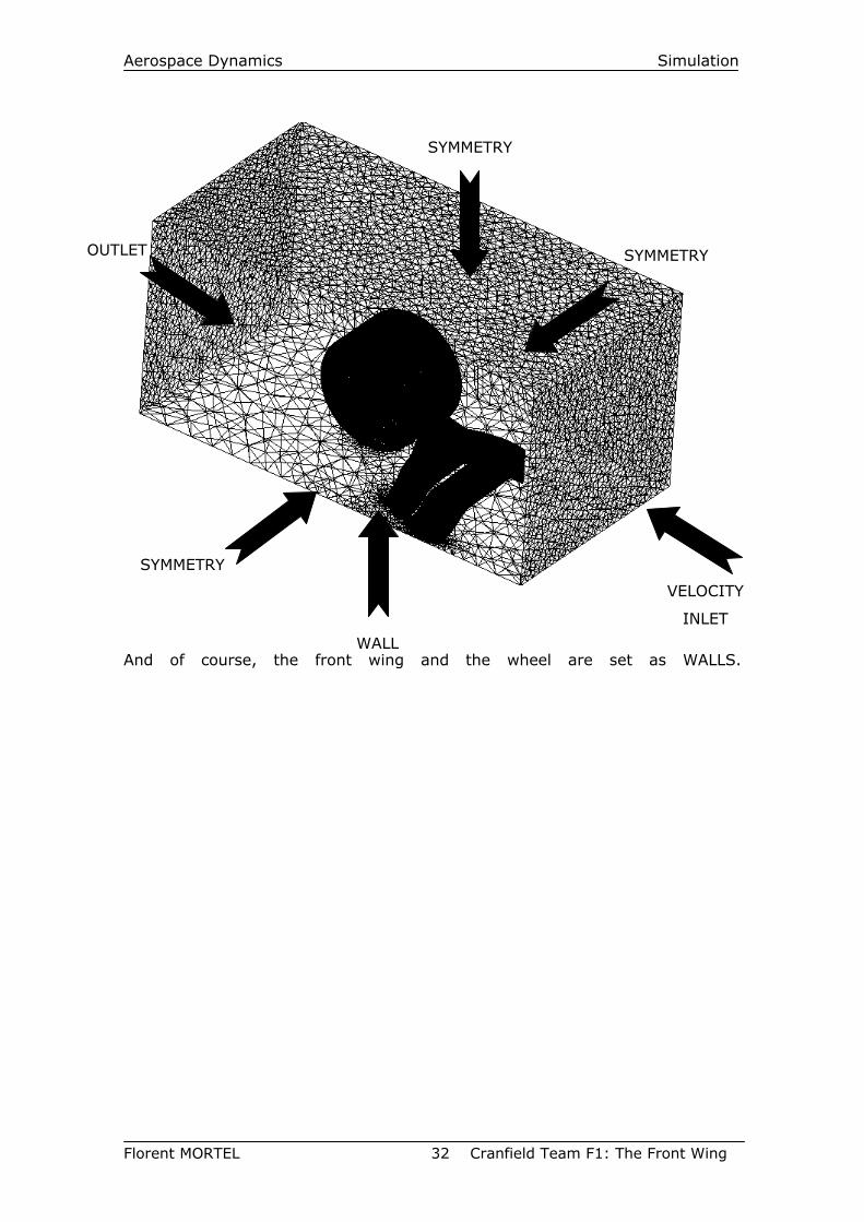
The boundary conditions have been set as follow:
-the inlet of the domain:
The flow upstream of the front wing is not disrupted by the other devices of the
car even if the flow may be disrupted if the car follows another one.
So the inlet was set as “velocity inlet” with an intensity and length scale
turbulence type:
-the airspeed at the entrance is equal to 60 m/s.
-the turbulence intensity is set to 3% which is a standard value
recommended (to get suitable results for the wheel (see the Analysis
part), other turbulence intensity (down to 0.1%) coefficients were tried
but the results did not change as expected).
-the length scale is set to 0.3 m which is the average length of the chord
of the two airfoils from the two-element wing.
-the front wing:
Set as a “wall”, of course…
-the ground:
set as a moving “wall”. Its speed is equal to the air velocity inlet one: 60 m/s.
-the wheel:
set a moving “wall”. The wheel was built as a cylinder and rotates around its
axis at 181.82 rad/s so that it is equal to a speed of 60 m/s on the track.
-the outlet of the domain:
set as “outflow”.
-the sides of the domain:
set as “symmetry”. It is obvious for the side that deals with the centre of the
car as the latter was split into two sections. For the other ones, the fact they
are far enough from the front wing and because of the “symmetry” boundary
characteristics –that are that the velocity vectors are parallel to the flow-
permits to set them as “symmetry” boundaries.
Aerospace Dynamics Simulation
Florent MORTEL 32 Cranfield Team F1: The Front Wing
And of course, the front wing and the wheel are set as WALLS.
SYMMETRY
WALL
VELOCITY
INLET
SYMMETRY
OUTLET SYMMETRY
Aerospace Dynamics Analysis
Florent MORTEL 33 Cranfield Team F1: The Front Wing
IV. ANALYSIS The analysis is based on the flow visualisation provided by Fieldview 8.2 and 9
with the results from Fluent 6.1.
Thanks to Fluent, the CL and CD values were calculated too but they are not the
primary concern of this study whose aim is to get more information about the
flow around the endplates of a Formula One front wing.
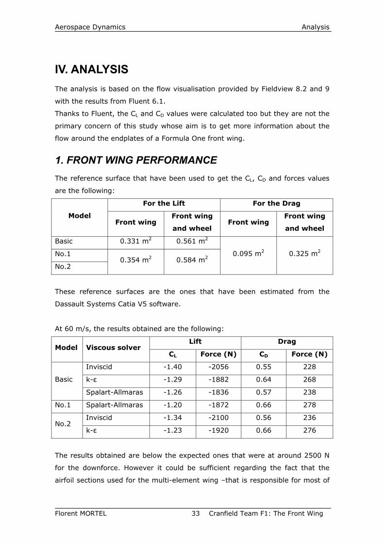
1. FRONT WING PERFORMANCE The reference surface that have been used to get the CL, CD and forces values
are the following:
For the Lift For the Drag
Model Front wing
Front wing
and wheel Front wing
Front wing
and wheel
Basic 0.331 m2 0.561 m2
No.1
No.2 0.354 m2 0.584 m2
0.095 m2 0.325 m2
These reference surfaces are the ones that have been estimated from the
Dassault Systems Catia V5 software.
At 60 m/s, the results obtained are the following:
Lift Drag Model Viscous solver
CL Force (N) CD Force (N)
Inviscid -1.40 -2056 0.55 228
k-ε -1.29 -1882 0.64 268 Basic
Spalart-Allmaras -1.26 -1836 0.57 238
No.1 Spalart-Allmaras -1.20 -1872 0.66 278
Inviscid -1.34 -2100 0.56 236 No.2
k-ε -1.23 -1920 0.66 276
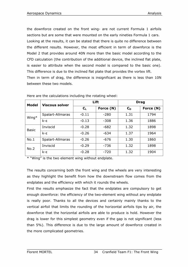
The results obtained are below the expected ones that were at around 2500 N
for the downforce. However it could be sufficient regarding the fact that the
airfoil sections used for the multi-element wing –that is responsible for most of
Aerospace Dynamics Analysis
Florent MORTEL 34 Cranfield Team F1: The Front Wing
the downforce created on the front wing- are not current Formula 1 airfoils
sections but are some that were mounted on the early nineties Formula 1 cars.
Looking at the results, it can be stated that there is quite no difference between
the different results. However, the most efficient in term of downforce is the
Model 2 that provides around 40N more than the basic model according to the
CFD calculation (the contribution of the additional device, the inclined flat plate,
is easier to attribute when the second model is compared to the basic one).
This difference is due to the inclined flat plate that provides the vortex lift.
Then in term of drag, the difference is insignificant as there is less than 10N
between these two models.
Here are the calculations including the rotating wheel:
Lift Drag Model Viscous solver
CL Force (N) CD Force (N)
Spalart-Allmaras -0.11 -280 1.31 1794 Wing*
k-ε -0.13 -308 1.36 1886
Inviscid -0.28 -682 1.32 1898 Basic
k-ε -0.26 -634 1.37 1964
No.1 Spalart-Allmaras -0.26 -676 1.30 1860
Inviscid -0.29 -736 1.32 1898 No.2
k-ε -0.28 -720 1.32 1904
* “Wing” is the two element wing without endplate.
The results concerning both the front wing and the wheels are very interesting
as they highlight the benefit from how the downstream flow comes from the
endplates and the efficiency with which it rounds the wheels.
First the results emphasize the fact that the endplates are compulsory to get
enough downforce: the efficiency of the two-element wing without any endplate
is really poor. Thanks to all the devices and certainly mainly thanks to the
vertical airfoil that limits the rounding of the horizontal airfoils tips by air, the
downforce that the horizontal airfoils are able to produce is hold. However the
drag is lower for this simplest geometry even if the gap is not significant (less
than 5%). This difference is due to the large amount of downforce created in
the more complicated geometries.
Aerospace Dynamics Analysis
Florent MORTEL 35 Cranfield Team F1: The Front Wing
Then the geometries designed with the big vertical airfoil deflect more air from
the wheel so that the drag produced by the latter is reduced compared to what
may be expected.
Therefore the gap in downforce between the second model and the basic one is
much higher than for the only front wing simulation. This difference is mainly
due to the lift the rotation of the wheels creates as the gap between the two
geometries is doubled with the k-ε viscous solver.
2. OBSERVED FLOW PATTERN
2.1 The multi-element airfoil
Thanks to the slope of the two-element airfoil along the span, the flow has
greatly been improved. First the fact of setting a gap between the lower surface
of the first element and the bottom of the vertical airfoil prevents the air from
rounding the endplates as it was expected during the design process. This
avoids the depression to be affected by the air rounding the tip from the high
pressure –the upper surface- to the low pressure –the lower one-. Fig. 24
shows the velocity intensity at the multi-element airfoil surface: velocities are
much higher along the wing span especially at the tip.
Then, the curvature of the wing at the middle of the span allows taking
advantage of the ground effect and so to higher the downforce. The streamlines
are closer to each other in this area. The wing works as a venturi with the
ground and so creates more loads on the front wing (see Fig. 25, 26, 28, 29, 30
and 31). The suction at the centre of the span has an influence along the whole
span on the lower surface as it is shown with the isobars from Fig. 29. Indeed
the air on the lower surface has a trend to curve its path to the inboard
direction much more than the one on the upper surface (see Fig. 32).
Finally, even if this is not the aim of this study and that the two elements of the
front wing has not be made for each other, the GAW-1, the first one, feeds with
air the lower surface of the second element quite well (see Fig. 30).
Aerospace Dynamics Analysis
Florent MORTEL 36 Cranfield Team F1: The Front Wing
2.2 Vertical airfoils
The vertical airfoils definitely help the flow to take an inboard direction.
The flow on the inboard side of the vertical airfoil is of course deflected as it can
not go through the airfoil. However, it is almost deflected upward because of
the high incidence of the main wing second element.
Then the flow on the outboard side of the vertical airfoil is sucked inboard. The
efficiency is highlighted thanks to the simulation provided by the basic model.
This is easily seen on Fig. 33 and Fig. 34 as the velocity vectors take the
inboard direction. However its efficiency is altered by the fact the air has to
round the wheels and because of the superpressure in front of the tyres.
Indeed, although a low pressure area would have been expected on the
outboard side, the latter is ruled by a high pressure area when it gets closer to
its trailing edge because of the proximity of the wheel.
So, air is sucked in the inboard direction from the leading edge of the vertical
airfoil and then, when it gets closer to the wheel, the bypass of the wheel takes
turn and favours this suction.
Although air seems to be well deflected inboard, this trend could be really
improved. Indeed, it can be seen on Fig. 33 and Fig. 34 that air particles
rounds the top tip of the vertical airfoil. Two factors are responsible for this flow
disruption: the depression on the outboard surface of the vertical airfoil and the
overpressure on the upper surface of the multi-element airfoil. Of course, air
particles go from the high to the low pressure and create a wing tip vortex at
the top of the NACA 68005.
Observing this phenomenon, the same flow pattern may have been found at
the bottom of the same airfoil section. But the depression is so important on
the lower surface of the multi-element airfoil that the suction from this location
totally reverse the direction of the vortex, the air particles travelling from the
outboard to the inboard surface of the vertical airfoil (see Fig. 33 and Fig. 34).
Finally one of the vertical airfoil great influences is to prevent the superpressure
from the tyres to extent forward until the surfaces of the two-element airfoil
(see Fig. 37). This allows protecting the loads created by the wing which is not
the case in the wing without any endplate.
Aerospace Dynamics Analysis
Florent MORTEL 37 Cranfield Team F1: The Front Wing
2.3 Flow over wheels / Horizontal flat plates
2.3.1 Wheel
Badly, the viscous solver used did not allow getting suitable results for the flow
induced by the rotating wheels. The rotation of the wheel is simulated (see Fig.
38) but the resulted flow from CFD does not match with the one from some
wind-tunnel tests made by previous research. To catch the separation that
should have occurred, the length scale was reduced as well as the turbulence
intensity but it does not change that much.
However, the pressure distribution (see Fig. 36) obtained shows the reason why
the wheels are responsible for half of the drag of the car: the front of the tyre is
a huge overpressure area –that extends quite far from ahead of the tyre (see
Fig. 37)- whereas the back of it, dominated by recirculated flow, is a low
pressure one retaining the car from moving forward. Fig.39 and Fig. 40 provide
the evidence of the efficiency of the endplates in term of deflection of the flow.
Indeed the distribution of pressure on the inboard side (left on Fig. 39 and Fig.
40) of the tyre shows lower pressure. That means that most of the flow has
been sucked inboard by the endplates.
By comparing the different models, it appears that the Model 2 is more efficient
than the Model 1 in term of drag. Apparently, the small NACA 68005 of the
Model 1 is too close from the wheel and, as its angle of attack is too low, it
forces air to take the direction of the wheel surface rather than deflecting it
from the tyre (see Fig. 41 and Fig. 42). That is the reverse effect from the
expected one.
2.3.2 Model 1
The first Model provides interesting results about its upper flat plate. From the
leading edge of the vertical airfoil to the apex of the upper flat plate, the
behaviour of the flow is of course the same as the basic model one. From this
point to the appearance of the small vertical airfoil, two vortices are created.
The first one, the strongest one is induced by the difference of pressure set by
the vertical airfoil. The second one is a result of the first one: indeed, as the
upper flat plate thickens the vertical airfoil upper tip, the flow rounding the tip
(and creating the first vortex) induces a secondary vortex stuck to the upper
Aerospace Dynamics Analysis
Florent MORTEL 38 Cranfield Team F1: The Front Wing
flat plate. As this creates a low pressure area and so lift instead of downforce
(see Fig. 43), the rounding flow induced by the vertical airfoil has to be
avoided.
2.3.3 Model 2
Fig. 44 and Fig. 45 show the difference between the basic model and the Model
2 velocity profiles at a height of 0.287m near the trailing edge of the vertical
airfoil. Because of the inclined flat plate, the flow is accelerated on the latter’s
upper surface compared to the flow provided by the basic front wing. However
the upper horizontal flat plate disrupts the flow and obliged air to bypass it by
using the side way for some particles of air. This makes the flow intensify the
high pressure on the wheel surface as these particles do not take benefit of
being deflecting inboard of the wheel. For the second model, this small plate
should be removed as well as it would not provide as much downforce as
expected because of its small size.
2.4 Inclined flat plates
As expected, a vortex is created from the apex of the flat plate. So the angle of
attack chosen -12 degrees- is sufficient to generate the resulted vortex and a
flow separation at the leading edge (see Fig. 46, Fig. 47 and Fig. 48). However
the vortex becomes flat close to the plate whereas it keeps its circular form at
its bottom. So maybe the angle of attack might have been increased.
The vortex is rotating under the flat plate and therefore, as the speed of the air
is higher thanks to the rotation of the flow, a low pressure area is created as
expected (see Fig. 49 and Fig. 50). However, the low pressure surface does not
extend until the trailing edge because of the disruption due to the wheel (see
Fig. 52 where the pressure becomes higher and higher when the section gets
closer to the trailing edge). Anyway the delta flat plate creates a low pressure
surface and even if its effect is lowered by the wheel when approaching the
trailing edge, it creates additional downforce and deflects the flow from the
wheel very efficiently. Badly the difference of pressure between the upper and
lower surface of the flat plate is also disrupted by the tip vortex from the
vertical airfoil (see Fig. 48 and Fig. 51).
Aerospace Dynamics Analysis
Florent MORTEL 39 Cranfield Team F1: The Front Wing
3. IMPROVEMENTS TO BE CARRIED OUT This part gives directions to improve the second model or give new direction of
designing the front wing. Some of them do not match each others and so it
would permit to carry out several studies so that they would be compared.
3.1 The multi-element airfoil
First, to carry out studies with better accuracy, it should be better to get data
from recent airfoils used in Formula 1.
The ride height of the front wing was set to 2.5 cm to get as much downforce
as possible. Badly, this height is too low and should be increased to at least 6
cm so that the car would not be too sensitive to the pitch and to the side of the
track when drivers try to get a tight path.
To get a significant gap between the lower surface of the first element and the
bottom of the vertical airfoil from each endplate, the two elements should be
twisted at their tip, keeping the same trailing edge height but so curving the
leading edge to decrease the incidence at the tip locations. This would permit to
help the endplates to prevent the air from rounding the first element tip from
the high to the low pressure by keeping a minimum height of the same first
element so that its ride height should be minimised along quite the whole span.
It would also reduce the difference of pressure close to the tips. This would
increase the ground effect too (and so the downforce) as the ground clearance
will be reduced along most of the span. However, a straight element may be
preferred if the aim is to suck air from outboard (see the end of 3.4)
3.2 Vertical airfoils
First, the small airfoil, even if it has not be tested on the second model, may be
abandoned as it has not shown a great influence on the first model (see Fig. 41
and Fig. 42). Otherwise, if it is kept, its angle of attack may be increased to at
least 30 degrees because of the influence of the wheel and it should be set
ahead so that it would deflect the air flow before reaching the superpressure
area. In this case, the aim of this small airfoil would be to dilute the
superpressure located on the wheels and maybe to decrease drag but it would
Aerospace Dynamics Analysis
Florent MORTEL 40 Cranfield Team F1: The Front Wing
not be significant. This would in fact transfer some drag from the tyre to the
front wing.
To allow more air to be deflected inboard the wheels, the vertical NACA 68005
airfoil should be twisted at its bottom near its trailing edge to increase the gap
between the tyre and this airfoil. A greater amount of air may be deflected in
this gap so that less air would have to hit the tyre and so a gain in drag may be
obtained.
Then, as the air rounding endplates at their bottom (because of the difference
of pressure between the outboard side of the NACA 68005 and the lower
surface of the multi-element airfoil) would not affect the second element that
much, an additional small horizontal airfoil (with a chord of around 10 to 15
cm) may be added at the trailing edge of the endplates on the inboard side to
suck air from the external side of them to the internal one. This would help the
flow to be deflected inboard again, to prevent this air to reach the tyre and so
again to avoid useless drag.
To avoid the wing tip vortex at the top of the vertical airfoil, a winglet may be
added at the top of the vertical airfoil. It should be done inboard (at 0.3 metre
above the reference plane, i.e. at the limit allowed by the regulation or by
following the airfoils’ elements upper surface shape to drive the air) and
outboard.
Finally, it should be interesting to see the difference between a vertical airfoil
curved in the other direction. Of course, the solution may be guessed and so
maybe an adaptive curvature may be chosen by the designer so that he could
produce the low and high pressure area at the place he wishes them.
Therefore, it could be possible to control the vortex at the tips (so at the top
and at the bottom) of the NACA 68005 by playing with the tip curvature of the
vertical airfoil.
3.3 Flow over wheels / Horizontal flat plates
The aim here is to take advantage as much as possible of this high pressure
zone even if does not seem that easy.
Aerospace Dynamics Analysis
Florent MORTEL 41 Cranfield Team F1: The Front Wing
A flat plate should be designed from the top of the vertical airfoil to the
downstream and outboard limit allowed by the regulation (something that looks
like the upper flat plate from the first geometry designed). In this way, air
rounding the vertical airfoil by the top would be limited and taking advantage of
the induced flow from the rotating wheel would still be possible. Therefore it
would not disrupt the inclined flat plate and its resulted vortex if the height of
this one is reduced as described in one of the following part.
3.4 Inclined flat plates
As the vortex becomes flat when it gets close to the lower surface of the
inclined flat plate, it should be tested by a higher angle of attack. Therefore
maybe the fact that the vortex core is closer to the plate induces higher speed
(and so a lower pressure area) next to the lower surface as the core is closer to
the surface. However, the vortex might get slower because of the friction next
to the lower surface of the flat plate.
Then, as the vortex flow is disrupted by the flow from the rotating wheel and
that the latter induces high pressure area at both upper and lower surface of
the flat plate, the downforce created by the flat plate would be risen if it was
set closer to the ground as the wheel is further at this location (as it is round!).
However, it should not be too close as the suction from the multi-element airfoil
may destroy the vortex. To keep the depression of the multi-element airfoil
from bursting the vortex, the vertical airfoil may be curved outboard at its
bottom so that the suction from the multi-element wing will not affect the
vortex (the same principle as the one from Fig. 20).
Another way to improve this device would be to higher the vortex size. To
perform this improvement, the flat plate leading edge should extent in width.
This would imply to cut the vertical airfoil just upon the upper surface of the
first element of the two-element wing. However, this will not alleviate the
downforce provided by the multi-element airfoil too much as it would only
affect the superpressure upon it. The design would have to be smooth as the
aim is to prevent the formation of vortices but the one from the flat plate.
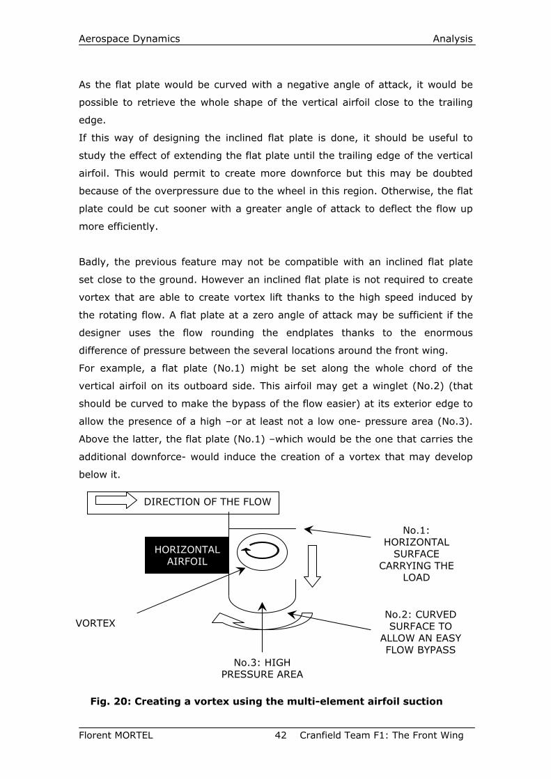
Aerospace Dynamics Analysis
Florent MORTEL 42 Cranfield Team F1: The Front Wing
As the flat plate would be curved with a negative angle of attack, it would be
possible to retrieve the whole shape of the vertical airfoil close to the trailing
edge.
If this way of designing the inclined flat plate is done, it should be useful to
study the effect of extending the flat plate until the trailing edge of the vertical
airfoil. This would permit to create more downforce but this may be doubted
because of the overpressure due to the wheel in this region. Otherwise, the flat
plate could be cut sooner with a greater angle of attack to deflect the flow up
more efficiently.
Badly, the previous feature may not be compatible with an inclined flat plate
set close to the ground. However an inclined flat plate is not required to create
vortex that are able to create vortex lift thanks to the high speed induced by
the rotating flow. A flat plate at a zero angle of attack may be sufficient if the
designer uses the flow rounding the endplates thanks to the enormous
difference of pressure between the several locations around the front wing.
For example, a flat plate (No.1) might be set along the whole chord of the
vertical airfoil on its outboard side. This airfoil may get a winglet (No.2) (that
should be curved to make the bypass of the flow easier) at its exterior edge to
allow the presence of a high –or at least not a low one- pressure area (No.3).
Above the latter, the flat plate (No.1) –which would be the one that carries the
additional downforce- would induce the creation of a vortex that may develop
below it.
VORTEX
HORIZONTAL AIRFOIL
No.1: HORIZONTAL
SURFACE CARRYING THE
LOAD
No.2: CURVED SURFACE TO
ALLOW AN EASY FLOW BYPASS
DIRECTION OF THE FLOW
No.3: HIGH PRESSURE AREA
Fig. 20: Creating a vortex using the multi-element airfoil suction
Aerospace Dynamics Analysis
Florent MORTEL 43 Cranfield Team F1: The Front Wing
To conclude, if new studies from this work are carried out, it may be interesting
too to get several models as it was done here to be able to assess the efficiency
of each device.
This chapter “Improvements to be carried out” shows many ways to create new
models. Of course, the list of ideas listed here is not exhaustive. This means
that there are still many ways to improve the front wing and that many studies
will still be carried out.
Aerospace Dynamics Conclusion
Florent MORTEL 44 Cranfield Team F1: The Front Wing
CONCLUSION This thesis includes three main steps: designing geometries, meshing them and
analysing them.
The design part which is very interesting was complicated to carry out.
However the link between the design part and the mesh part has to be done
carefully. Indeed the design has to be often modified to clean the geometries so
that no extra and useless edges may occur in the grid generation software. This
makes the meshing step easier and it becomes a gain of time during the grid
generation process which is the longer to carry out. Then, the simulation runs
after picking the right solvers and settings. Finally the analysis permits to
confirm the design, to modify it, to improve and to find new devices that would
be used to undertake another loop.
The loop carried out in this thesis deals with three geometries. The first one
assessed the contribution of the vertical airfoil that is present in the two other
geometries as well. The vertical airfoil permits to deflect air from the front
wheels and so to reduce the drag. It also prevents the superpressure from the
wheel to extent until the multi-element airfoil surfaces which is the most
important downforce creating device.
The low curvature of the multi-element horizontal airfoil was assessed and the
gain due to the ground effect appears to be quite important.
Then the Model 1 was built to evaluate the small vertical NACA 68005 close to
the wheel. This airfoil is not useful as the flow already rounds the wheel by
itself at this location. So if this device remains, it should be attached forward on
the front wing and should get a higher angle of attack to divert air more than
the wheel does.
Finally, additionally to deflect the air from the wheels, the Model 2 endplates
create downforce thanks to the vortex (negative) lift created by the inclined flat
plate. The expected additional load has been created even if it was hoped to be
bigger.
Aerospace Dynamics Conclusion
Florent MORTEL 45 Cranfield Team F1: The Front Wing
This study permits to run simple front wing shapes with CFD, to assess them
and to imply new design. Although the FIA Formula 1 technical regulation sets a
lot of constraints, maybe the latter is the engine of aerodynamics research in
Formula 1.
Aerospace Dynamics Bibliography
Florent MORTEL 46 Cranfield Team F1: The Front Wing
BIBLIOGRAPHY Renaud de Laborderie, Jean-Louis Moncet and Giorgio Piola, (March 1991 to
March 2003). Revue de détails in Sport-Auto No 351 to No 500. Emap France,
Paris.
Katz J., (1995). Race Car Aerodynamics: Designing for Speed. Bentley
Publishers, Cambridge (USA).
Mortel F., (2002). L’aérodynamique dans l’automobile. Memoir for the U.T.B.M.
(University of Technology of Belfort-Montbéliard). Citing Internet ressources
(WWW document). http://site.voila.fr/mortelfl/ht02.pdf (accessed 15th may
2003)
Katz J., (1985). Investigation of Negative Lifting Surfaces Attached to an Open-
Wheel Racing Car Configuration. SAE Report No 850283.
Fackrell J.E. and Harvey J.K., (1974). The aerodynamics of an Isolated Road
Wheel in Proceedings of the Second Symposium on Aerodynamics of Sports
and Competition Automobiles, (1975). Collection of AIAA papers by Pershing
Bernard, Western Periodicals Co., North Hollywood, CA.
Stapleford W. R. and Carr G. W., (1970). Aerodynamic characteristics of
exposed rotating wheels, Reports MIRA/AIC-1970/2.
Katz J. and Largman R., (1989). Experimental study of the aerodynamic
interaction between an enclosed-wheel racing-car and its rear wing in
Transactions of the ASME-Journal of Fluids Engineering, vol. 111, no. 2, p. 154-
159, 1989. American Society of Mechanical Engineers, New York.
Katz J., (1995). High-lift wing design for race-car applications in The Journal of
Passengers cars vol.104 part 2, SAE Paper 951976. Los Angeles.
Aerospace Dynamics References
Florent MORTEL 47 Cranfield Team F1: The Front Wing
REFERENCES 1. Florent MORTEL. Photographies made at Donington Park Museum. 17th
February 2003.
2. Pierre Ménard, (2000). The Great Encyclopedia of Formula 1, 1950-
1999: 50 years of Formula 1. London, Constable and Robinson.
Or : Pierre Ménard, (1999). La grande encyclopédie de la formule 1,
1950-1999: 50 ans de Formule 1. Chronosports Editeur.
3. Renaud de Laborderie, Jean-Louis Moncet and Giorgio Piola, (March 1991
to March 2003). Revue de détails in Sport-Auto No 351 to No 496. Emap
France, Paris.
4. Jean-Eric Raoul (August 2003). La mémoire de Sport-Auto: Jim Hall.
Sport-Auto No 499. Emap France, Paris.
5. Howard K. (September 2000). Gurney Flap. Edition of Motorsport
magazine , England. Cited in: Dan Gurney’s All American Drivers Online
(WWW document) http://www.allamericanracers.com/gurney_flap.html
(accessed 14th may 2003).
6. Florent MORTEL. Photography made at Cranfield University. May 2003.
7. FIA 2003 Formula One Technical Regulations.
FEDERATION INTERNATIONALE DE L'AUTOMOBILE
8, Place de la Concorde - 75008 Paris - France
8. FIA 2003 Formula One Sporting Regulations.
FEDERATION INTERNATIONALE DE L'AUTOMOBILE
8, Place de la Concorde - 75008 Paris – France
Aerospace Dynamics References
Florent MORTEL 48 Cranfield Team F1: The Front Wing
9. Fackrell J.E. and Harvey J.K., (1974). The aerodynamics of an Isolated
Road Wheel in Proceedings of the Second Symposium on Aerodynamics
of Sports and Competition Automobiles, (1975). Collection of AIAA
papers by Pershing Bernard, Western Periodicals Co., North Hollywood,
CA.
10. Tyre for dry surface (“grooved tyre”). Cited in: Michelin F1 web site
(WWW document).
http://www.michelinf1.com/content/xml/pneu_popup1_en.xml
(accessed in june 2003)
11. Pointwise, Inc.-Fort Worth, Texas–United States of America. Gridgen
User Manual. Accessed on line.
12. Fluent Europe Ltd-Sheffield business park-Europa link-Sheffield-S9 1XU-
England, (2003). Fluent 6.0 User’s Guide. Accessed on Cranfield
University web site.
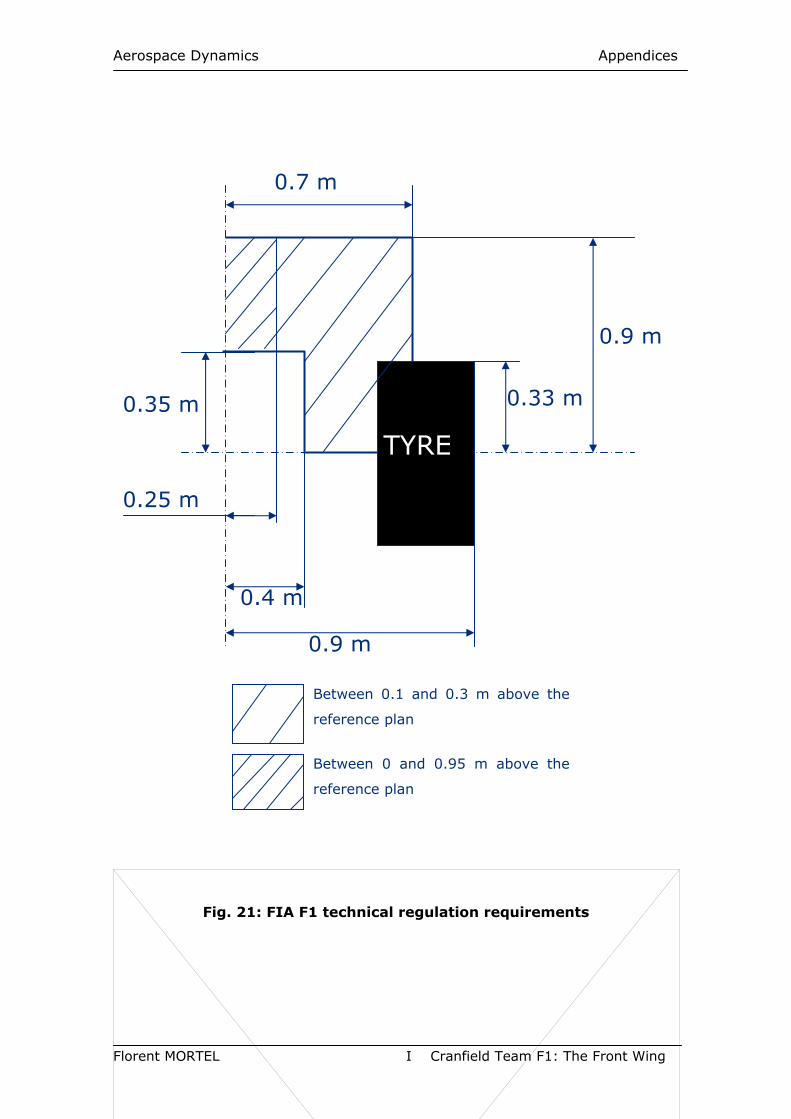
Aerospace Dynamics Appendices
Florent MORTEL I Cranfield Team F1: The Front Wing
Fig. 21: FIA F1 technical regulation requirements
0.9 m
0.9 m
TYRE
0.7 m
0.4 m
0.33 m 0.35 m
0.25 m
Between 0.1 and 0.3 m above the
reference plan
Between 0 and 0.95 m above the
reference plan
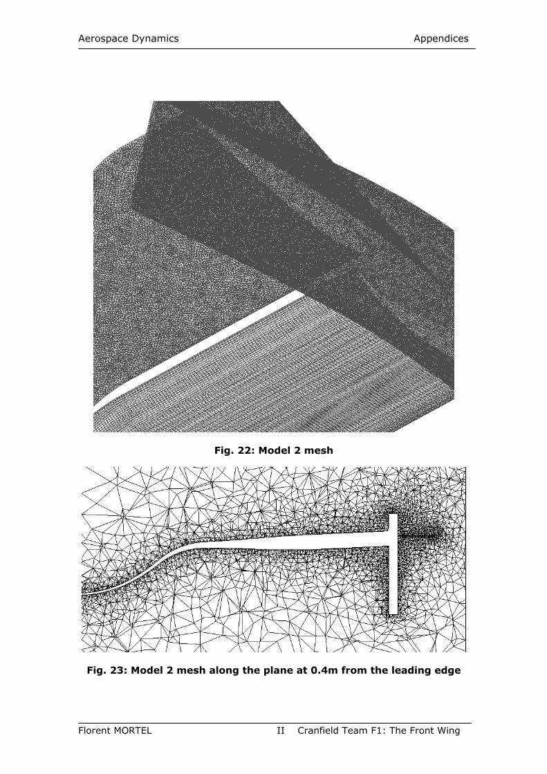
Aerospace Dynamics Appendices
Florent MORTEL II Cranfield Team F1: The Front Wing
Fig. 22: Model 2 mesh
Fig. 23: Model 2 mesh along the plane at 0.4m from the leading edge
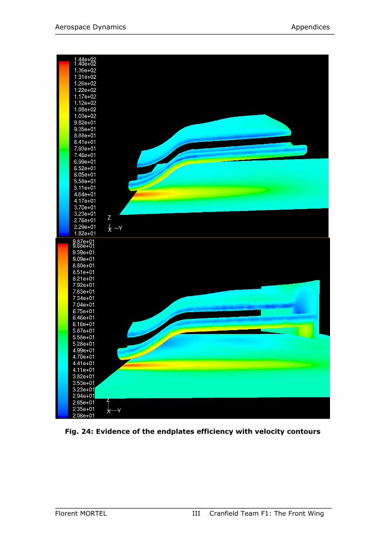
Aerospace Dynamics Appendices
Florent MORTEL III Cranfield Team F1: The Front Wing
Fig. 24: Evidence of the endplates efficiency with velocity contours
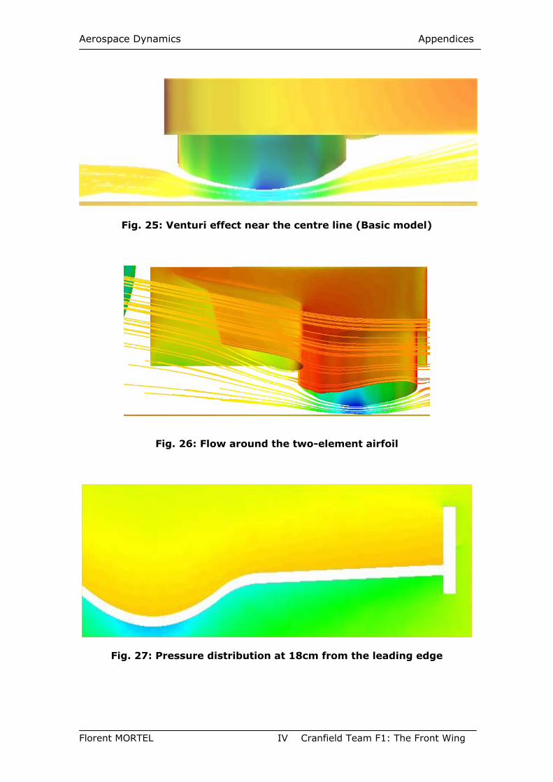
Aerospace Dynamics Appendices
Florent MORTEL IV Cranfield Team F1: The Front Wing
Fig. 25: Venturi effect near the centre line (Basic model)
Fig. 26: Flow around the two-element airfoil
Fig. 27: Pressure distribution at 18cm from the leading edge
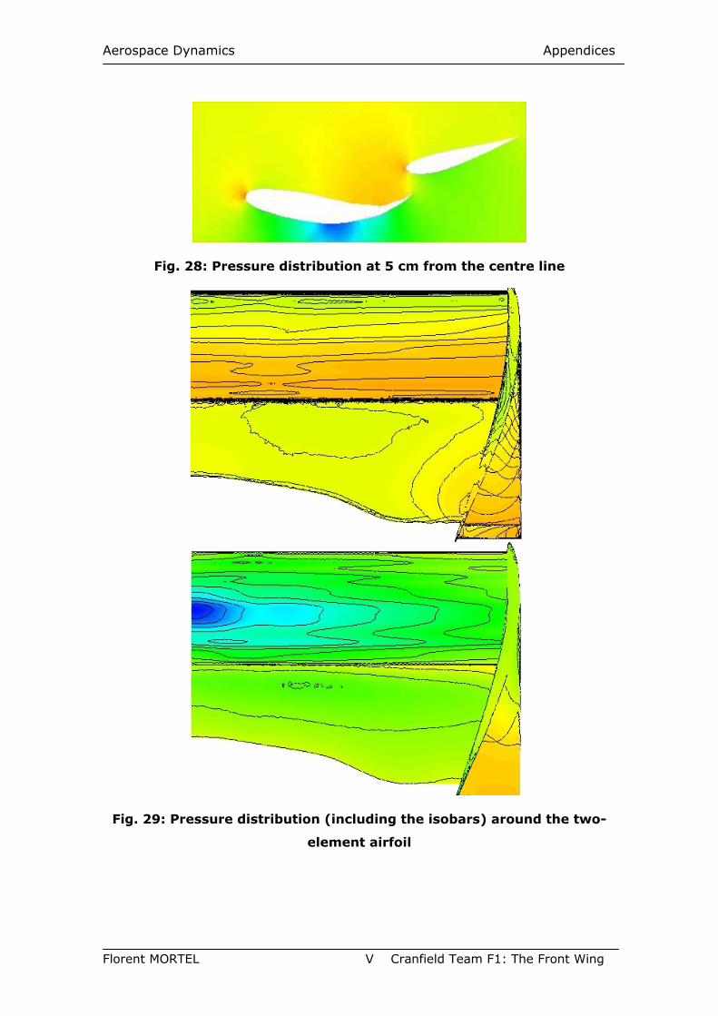
Aerospace Dynamics Appendices
Florent MORTEL V Cranfield Team F1: The Front Wing
Fig. 28: Pressure distribution at 5 cm from the centre line
Fig. 29: Pressure distribution (including the isobars) around the two-
element airfoil
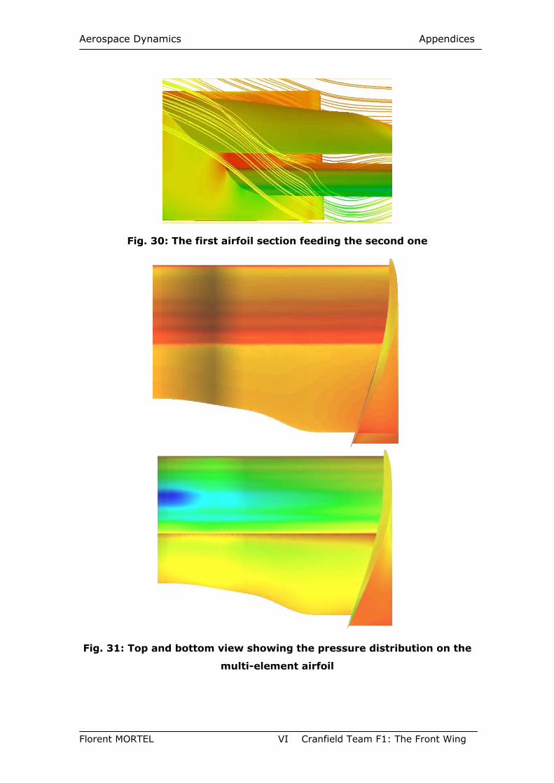
Aerospace Dynamics Appendices
Florent MORTEL VI Cranfield Team F1: The Front Wing
Fig. 30: The first airfoil section feeding the second one
Fig. 31: Top and bottom view showing the pressure distribution on the
multi-element airfoil
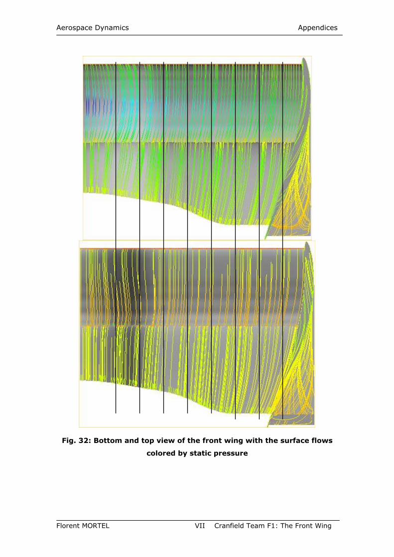
Aerospace Dynamics Appendices
Florent MORTEL VII Cranfield Team F1: The Front Wing
Fig. 32: Bottom and top view of the front wing with the surface flows
colored by static pressure
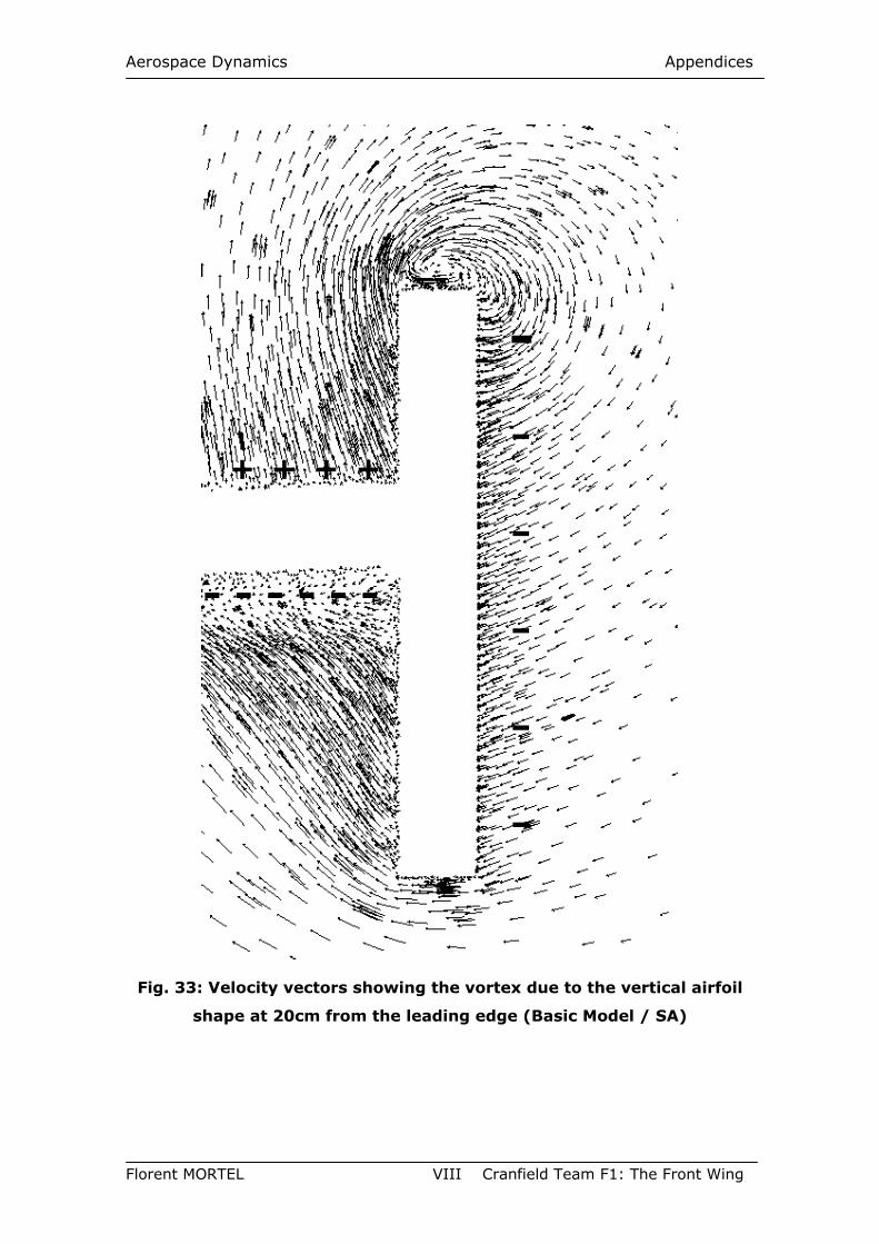
Aerospace Dynamics Appendices
Florent MORTEL VIII Cranfield Team F1: The Front Wing
Fig. 33: Velocity vectors showing the vortex due to the vertical airfoil
shape at 20cm from the leading edge (Basic Model / SA)
+ + + +
- - - - - -
-
-
-
-
-
-
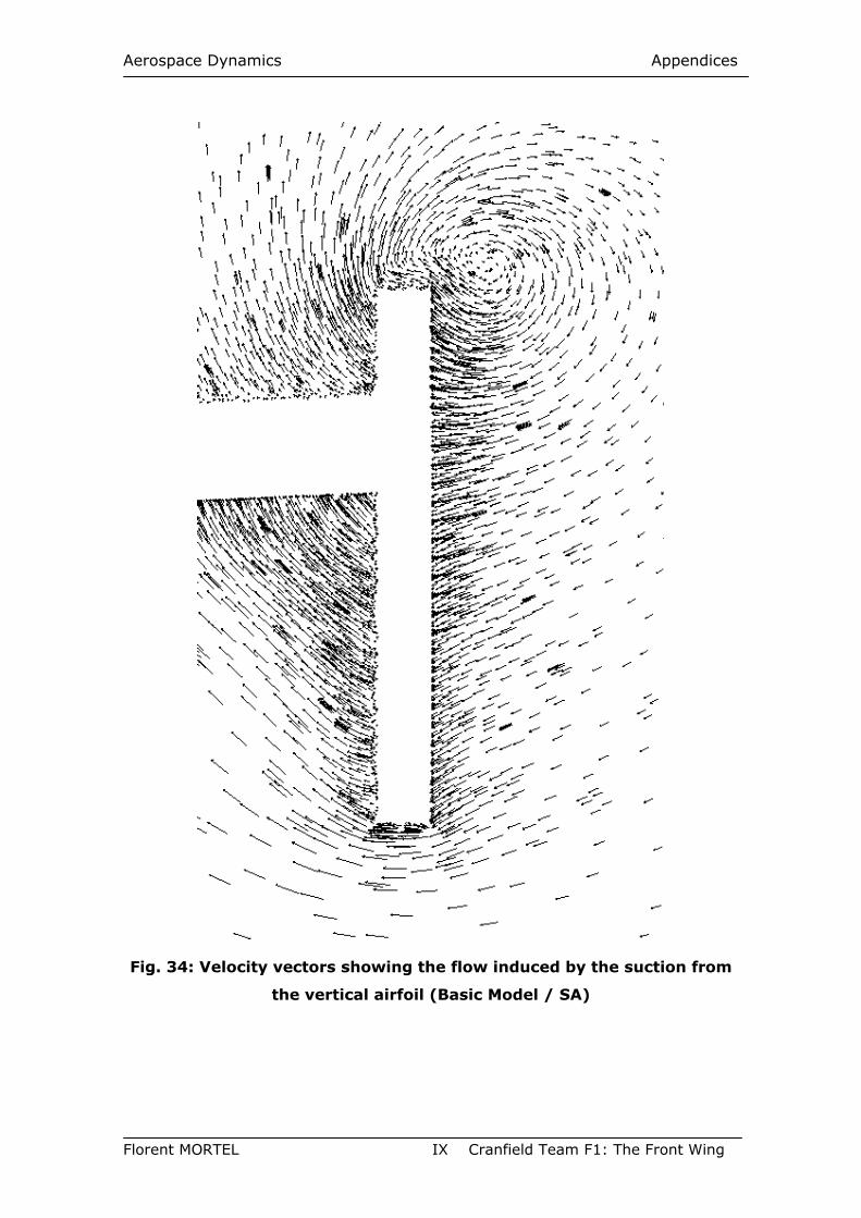
Aerospace Dynamics Appendices
Florent MORTEL IX Cranfield Team F1: The Front Wing
Fig. 34: Velocity vectors showing the flow induced by the suction from
the vertical airfoil (Basic Model / SA)
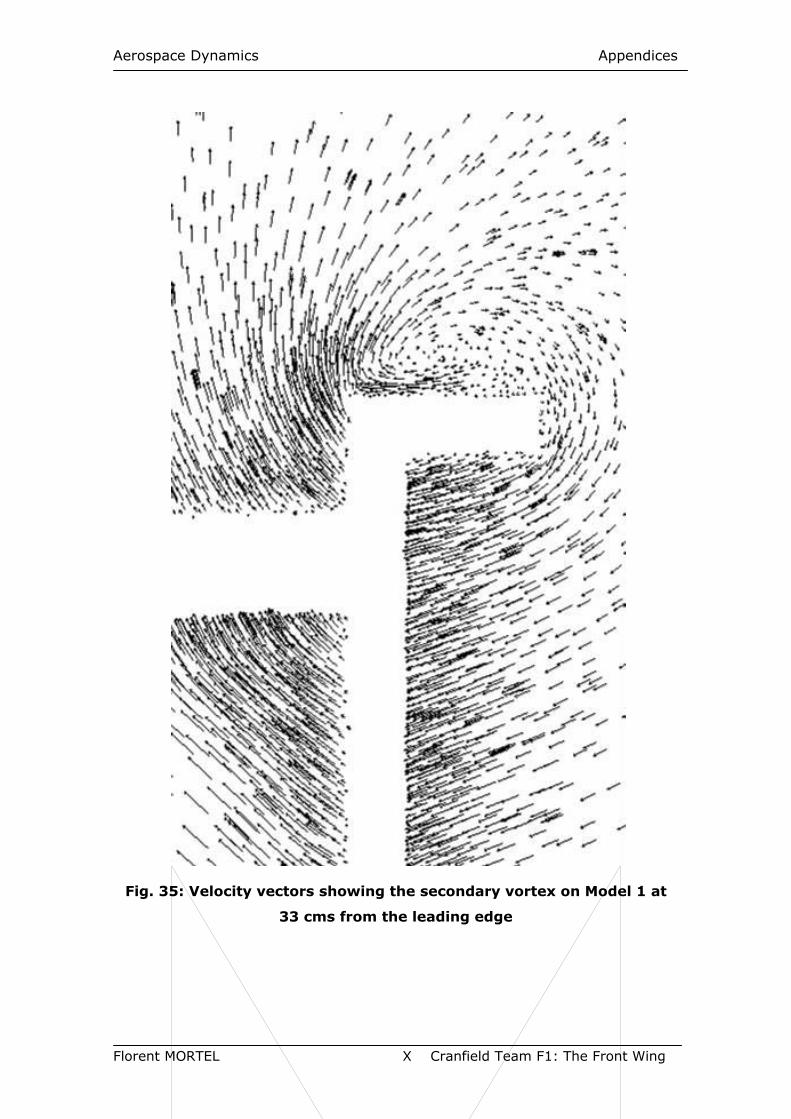
Aerospace Dynamics Appendices
Florent MORTEL X Cranfield Team F1: The Front Wing
Fig. 35: Velocity vectors showing the secondary vortex on Model 1 at
33 cms from the leading edge
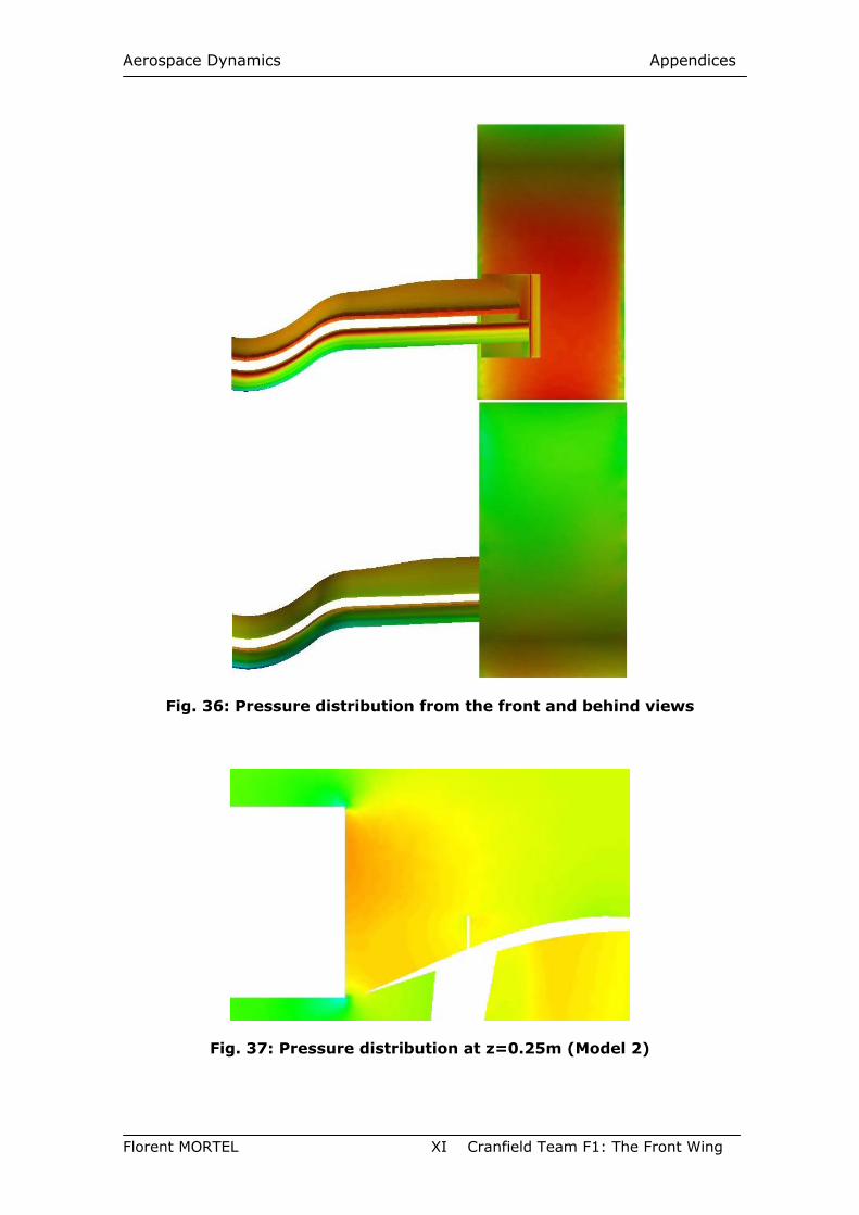
Aerospace Dynamics Appendices
Florent MORTEL XI Cranfield Team F1: The Front Wing
Fig. 36: Pressure distribution from the front and behind views
Fig. 37: Pressure distribution at z=0.25m (Model 2)
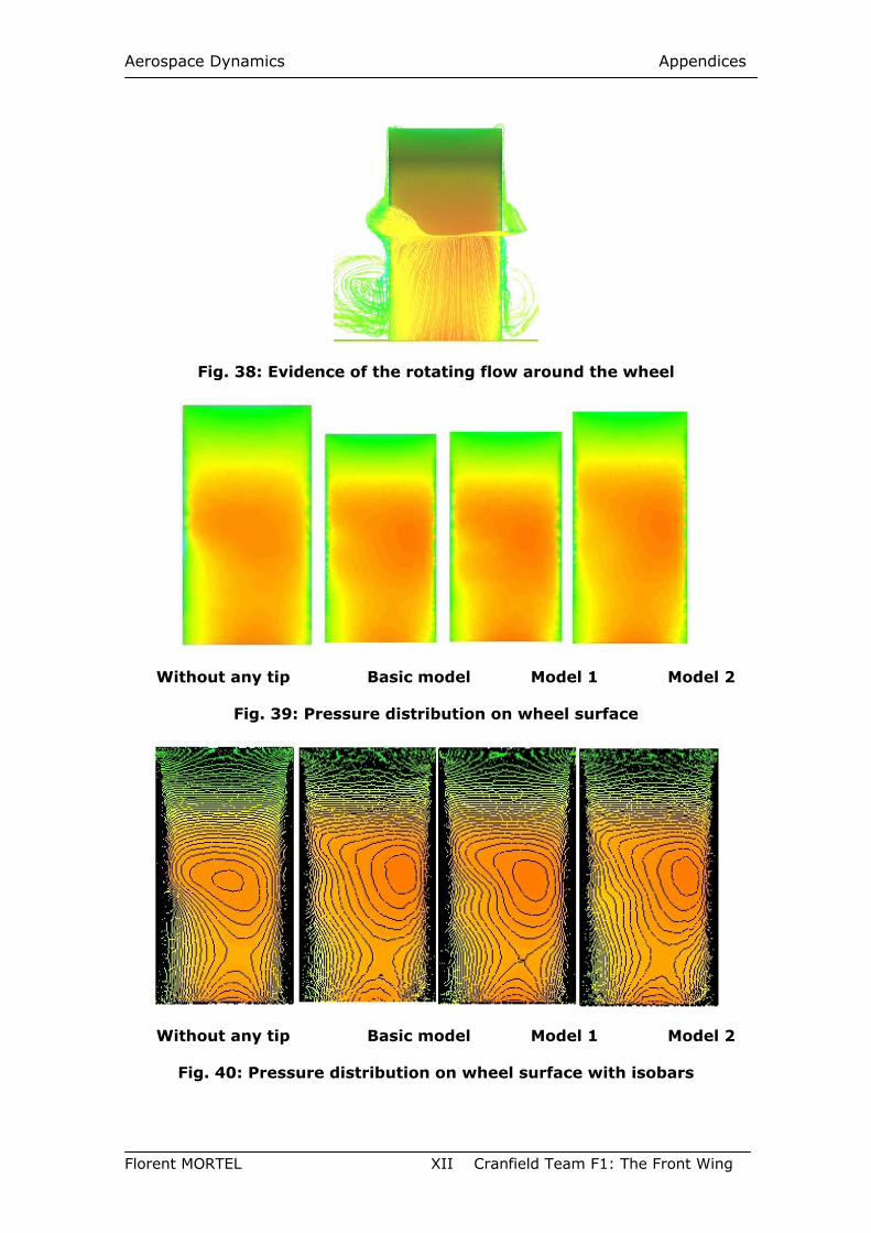
Aerospace Dynamics Appendices
Florent MORTEL XII Cranfield Team F1: The Front Wing
Fig. 38: Evidence of the rotating flow around the wheel
Without any tip Basic model Model 1 Model 2
Fig. 39: Pressure distribution on wheel surface
Without any tip Basic model Model 1 Model 2
Fig. 40: Pressure distribution on wheel surface with isobars
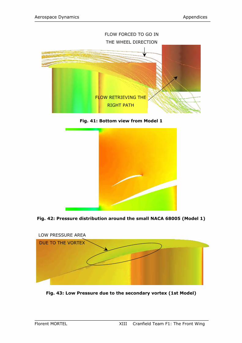
Aerospace Dynamics Appendices
Florent MORTEL XIII Cranfield Team F1: The Front Wing
Fig. 41: Bottom view from Model 1
Fig. 42: Pressure distribution around the small NACA 68005 (Model 1)
Fig. 43: Low Pressure due to the secondary vortex (1st Model)
FLOW FORCED TO GO IN
THE WHEEL DIRECTION
FLOW RETRIEVING THE
RIGHT PATH
LOW PRESSURE AREA
DUE TO THE VORTEX
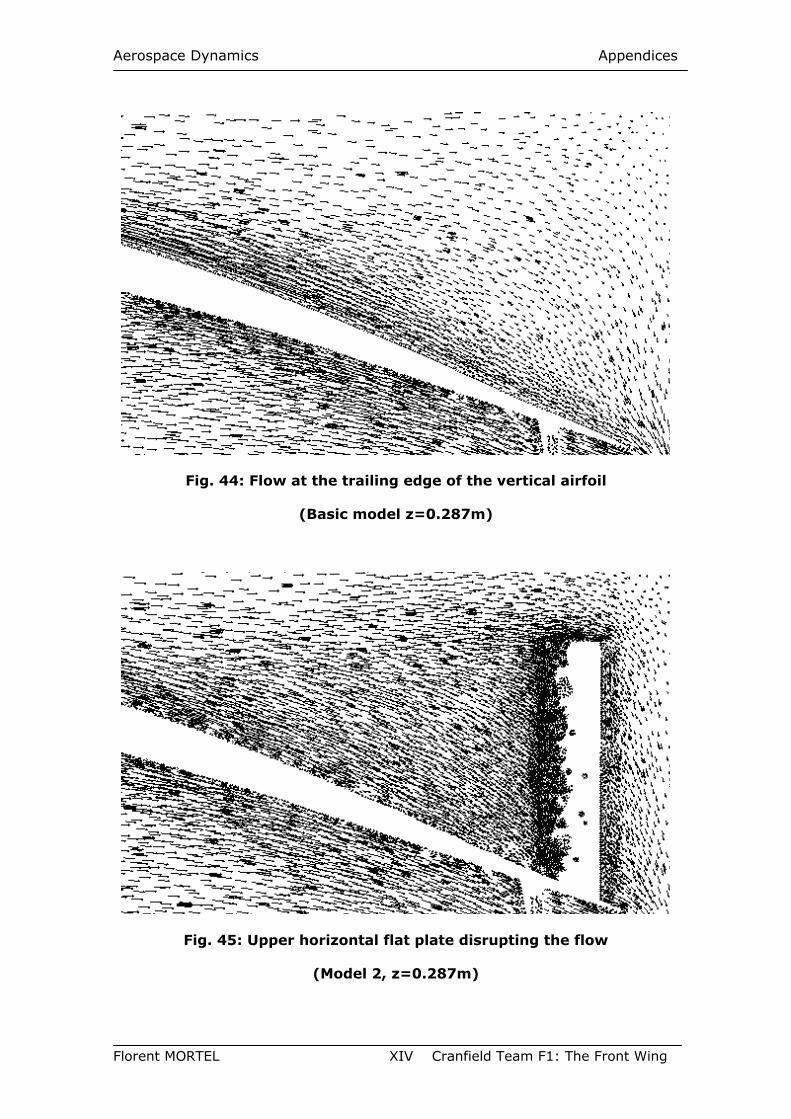
Aerospace Dynamics Appendices
Florent MORTEL XIV Cranfield Team F1: The Front Wing
Fig. 44: Flow at the trailing edge of the vertical airfoil
(Basic model z=0.287m)
Fig. 45: Upper horizontal flat plate disrupting the flow
(Model 2, z=0.287m)
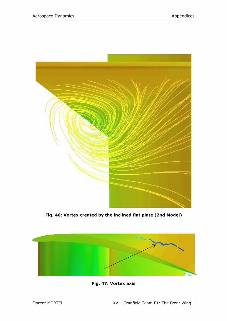
Aerospace Dynamics Appendices
Florent MORTEL XV Cranfield Team F1: The Front Wing
Fig. 46: Vortex created by the inclined flat plate (2nd Model)
Fig. 47: Vortex axis
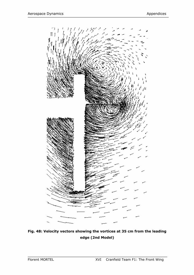
Aerospace Dynamics Appendices
Florent MORTEL XVI Cranfield Team F1: The Front Wing
Fig. 48: Velocity vectors showing the vortices at 35 cm from the leading
edge (2nd Model)
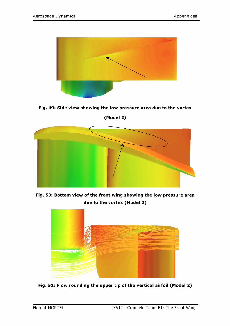
Aerospace Dynamics Appendices
Florent MORTEL XVII Cranfield Team F1: The Front Wing
Fig. 49: Side view showing the low pressure area due to the vortex
(Model 2)
Fig. 50: Bottom view of the front wing showing the low pressure area
due to the vortex (Model 2)
Fig. 51: Flow rounding the upper tip of the vertical airfoil (Model 2)
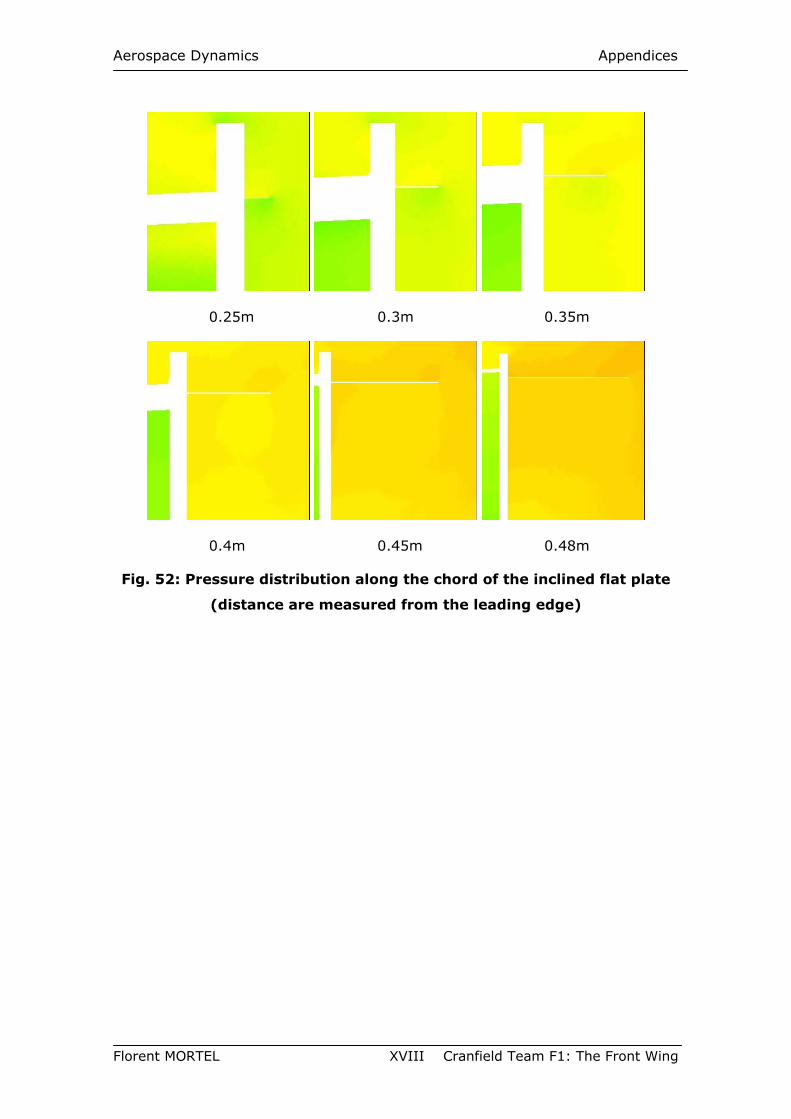
Aerospace Dynamics Appendices
Florent MORTEL XVIII Cranfield Team F1: The Front Wing
0.25m 0.3m 0.35m
0.4m 0.45m 0.48m
Fig. 52: Pressure distribution along the chord of the inclined flat plate
(distance are measured from the leading edge)