crane control class 6121 - the electric … field resistor limits no load hoisting speed to 250% of...
TRANSCRIPT

CR
AN
E C
ON
TR
OL
C
LA
SS
612
1
Crane Control Class 6121
Catalog
17
CONTENTS
Description . . . . . . . . . . . . . . . . . . . . . . . . . . . . . . . . . . . . . . . . . . . . . . . . . . . . .PageGeneral Information and Pricing . . . . . . . . . . . . . . . . . . . . . . . . . . . . . . . . . . . . . . . . 44Controller Modifications and Application Data . . . . . . . . . . . . . . . . . . . . . . . . . . . . . 48Wiring Diagrams . . . . . . . . . . . . . . . . . . . . . . . . . . . . . . . . . . . . . . . . . . . . . . . . . . . . 54Application Data . . . . . . . . . . . . . . . . . . . . . . . . . . . . . . . . . . . . . . . . . . . . . . . . . . . . 56Dimensions and Weights . . . . . . . . . . . . . . . . . . . . . . . . . . . . . . . . . . . . . . . . . . . . . 58Rectified DC Constant Potential HWR Hoist Control . . . . . . . . . . . . . . . . . . . . . . . . 60DC Mill Auxiliary Control . . . . . . . . . . . . . . . . . . . . . . . . . . . . . . . . . . . . . . . . . . . . . . 62
Crane Control Class 6121Frontline® DC Crane Control
CR
AN
E C
ON
TR
OL
C
LA
SS
612
1
© 2003 The Electric Controller & Mfg. Co., LLC All Rights Reserved
4401/17
GENERAL INFORMATION AND PRICING
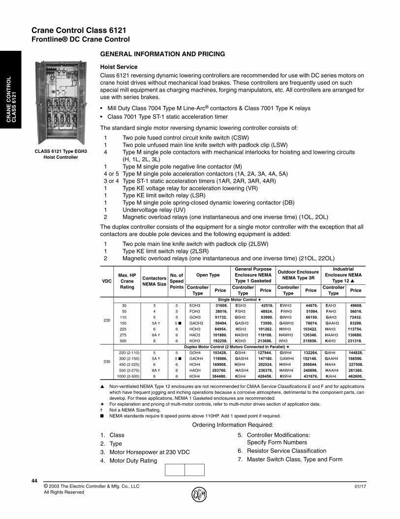
Hoist ServiceClass 6121 reversing dynamic lowering controllers are recommended for use with DC series motors on crane hoist drives without mechanical load brakes. These controllers are frequently used on such special mill equipment as charging machines, forging manipulators, etc. All controllers are arranged for use with series brakes.
• Mill Duty Class 7004 Type M Line-Arc® contactors & Class 7001 Type K relays• Class 7001 Type ST-1 static acceleration timer
The standard single motor reversing dynamic lowering controller consists of:
1 Two pole fused control circuit knife switch (CSW)1 Two pole unfused main line knife switch with padlock clip (LSW)4 Type M single pole contactors with mechanical interlocks for hoisting and lowering circuits
(H, 1L, 2L, 3L)1 Type M single pole negative line contactor (M)4 or 5 Type M single pole acceleration contactors (1A, 2A, 3A, 4A, 5A)3 or 4 Type ST-1 static acceleration timers (1AR, 2AR, 3AR, 4AR)1 Type KE voltage relay for acceleration lowering (VR)1 Type KE limit switch relay (LSR)1 Type M single pole spring-closed dynamic lowering contactor (DB)1 Undervoltage relay (UV)2 Magnetic overload relays (one instantaneous and one inverse time) (1OL, 2OL)
The duplex controller consists of the equipment for a single motor controller with the exception that all contactors are double pole devices and the following equipment is added:
1 Two pole main line knife switch with padlock clip (2LSW)1 Type KE limit switch relay (2LSR)2 Magnetic overload relays (one instantaneous and one inverse time) (21OL, 22OL)
▲ Non-ventilated NEMA Type 12 enclosures are not recommended for CMAA Service Classifications E and F and for applications which have frequent jogging and inching operations because a corrosive atmosphere, detrimental to the component parts, can develop. For these applications, NEMA 1 Gasketed enclosures are recommended.
a For explanation and pricing of multi-motor controls, refer to multi-motor drives section of application data.✝ Not a NEMA Size/Rating.■ NEMA standards require 6 speed points above 110HP. Add 1 speed point if required.
Ordering Information Required:
VDCMax. HP Crane Rating
Contactors NEMA Size
No. of Speed Points
Open TypeGeneral Purpose Enclosure NEMA Type 1 Gasketed
Outdoor Enclosure NEMA Type 3R
Industrial Enclosure NEMA
Type 12 ▲Controller
TypePrice
Controller Type
PriceController
TypePrice
Controller Type
Price
230
Single Motor Control a
35 3 5 EOH3 31608. ESH3 42516. EWH3 44676. EAH3 49608.
55 4 5 FOH3 38016. FSH3 48924. FWH3 51084. FAH3 56016.
110 5 5 GOH3 51732. GSH3 63990. GWH3 66150. GAH3 72432.
150 5A ✝ 5 ■ GAOH3 59494. GASH3 73590. GAWH3 76074. GAAH3 83298.
225 6 6 HOH3 84954. HSH3 101262. HWH3 103422. HAH3 113754.
275 6A ✝ 6 HAO3 101880. HASH3 118108. HAWH3 120348. HAAH3 130680.
500 8 6 KOH3 192258. KSH3 213696. WH3 215856. KAH3 231318.
230
Duplex Motor Control (2 Motors Connected In Parallel) a
220 (2-110) 5 5 GOH4 103428. GSH4 127944. GWH4 132264. GAH4 144828.
300 (2-150) 5A ✝ 5 ■ GAOH4 118986. GASH4 147180. GAWH4 152148. GAAH4 166596.
450 (2-225) 6 6 HOH4 169908. HSH4 202524. HWH4 206844. HAH4 227508.
550 (2-275) 6A ✝ 6 HAOH 203760. HASH4 236376. HAWH4 240696. HAAH4 261360.
1000 (2-500) 8 6 KOH4 384480. KSH4 426456. KWH4 431676. KAH4 462600.
1. Class
2. Type 3. Motor Horsepower at 230 VDC4. Motor Duty Rating
5. Controller Modifications:Specify Form Numbers
6. Resistor Service Classification
7. Master Switch Class, Type and Form
CLASS 6121 Type EGH3 Hoist Controller

Crane Control Class 6121Frontline® DC Crane Control
CR
AN
E C
ON
TR
OL
C
LA
SS
612
1
4501/17 © 2003 The Electric Controller & Mfg. Co., LLC
All Rights Reserved
PRICING INFORMATION AND APPLICATION DATA
Hoist Service
A complete set of motor control equipment consists of a controller, separately mounted Tab-Weld® resistors, and a master switch. The following tables are for selecting the resistors and master switches used with Class 6121 Hoist controllers.
★ It is recommended that hoist resistors be selected based on the 1/2 hour motor horsepower rating unless specified otherwise.† For resistors mounted in racks – refer to Class 6715.■ Duplex controllers require two sets of resistors, one set for each motor.● Class 162 is recommended for standard crane duty.
Class 172 is recommended for severe crane duty.Consult factory for other NEMA Classes.For explanation of NEMA Resistor Classifications – refer to Class 6715 Application Data.
▲ Teaser field resistor limits no load hoisting speed to 250% of motor rated speed. No modification of the controller is required.
Accessories
Brakes . . . . . . . . . . . . . . . . . . . . . . . . . . . . . . . . . . . . . . . . . . . . . . . . . . . . . . . . . . . . . . . . . . . . . . . . . . . . . . . see Class 5010 or 5015
Manual-Magnetic Disconnect Switch . . . . . . . . . . . . . . . . . . . . . . . . . . . . . . . . . . . . . . . . . . . . . . . . . . . . . . . . . . . . . . .see Class 6140YOUNGSTOWN® Power Limit Switch . . . . . . . . . . . . . . . . . . . . . . . . . . . . . . . . . . . . . . . . . . . . . . . . . . . . . . . . . . . . . .see Class 6170
Tab-Weld® Resistor Selection Table ★ †
Maximum HP Rating Single Motor ■
Price Price AdditionsNEMA Class ●
Teaser Field Resistor ▲162-DL 172-DL
5 8784. 8784. 5490.7-1/2 7560. 7560. 3690.10 6246. 6588. 3690.
15 6660. 7254. 1890.20 7110. 8928. 1890.25 7560. 10584. 1890.
30 8784. 12294. 1890.35 10080. 14112. 1890.40 11268. 15768. 1890.
45 12546. 17568. 3060.50 13806. 19332. 3060.60 16182. 22662. 3060.
65 17514. 24516. 3060.70 18702. 26190. 3690.75 19980. 27972. 3690.
90 23616. 33066. 3690.100 26136. 36594. 3690. 135 34776. 48690. 6030.
150 38448. 53820. 6030.200 50832. 71172. 7560.250 64692. 90576. 10530.
275 70830. 99162. 11970.300 76950. 107730. 11970.325 83286. 116604. 13140.
375 95634. 133902. 13140.500 129376. 181152. 22860.
Master Switch Selection Table
Class 9004 VM or CM NEMA 1 Enclosed
Drive Speed Points Control TypeVM CM
Type Price Type Price
Hoist5 W VG12 5550. GG12 6426.
6 W VG16 8638. CG16 9330.
Modifications
Description Optional Feature Form LetterPrice Addition
VM CM
Spring Return to Off Point S 888. 888.
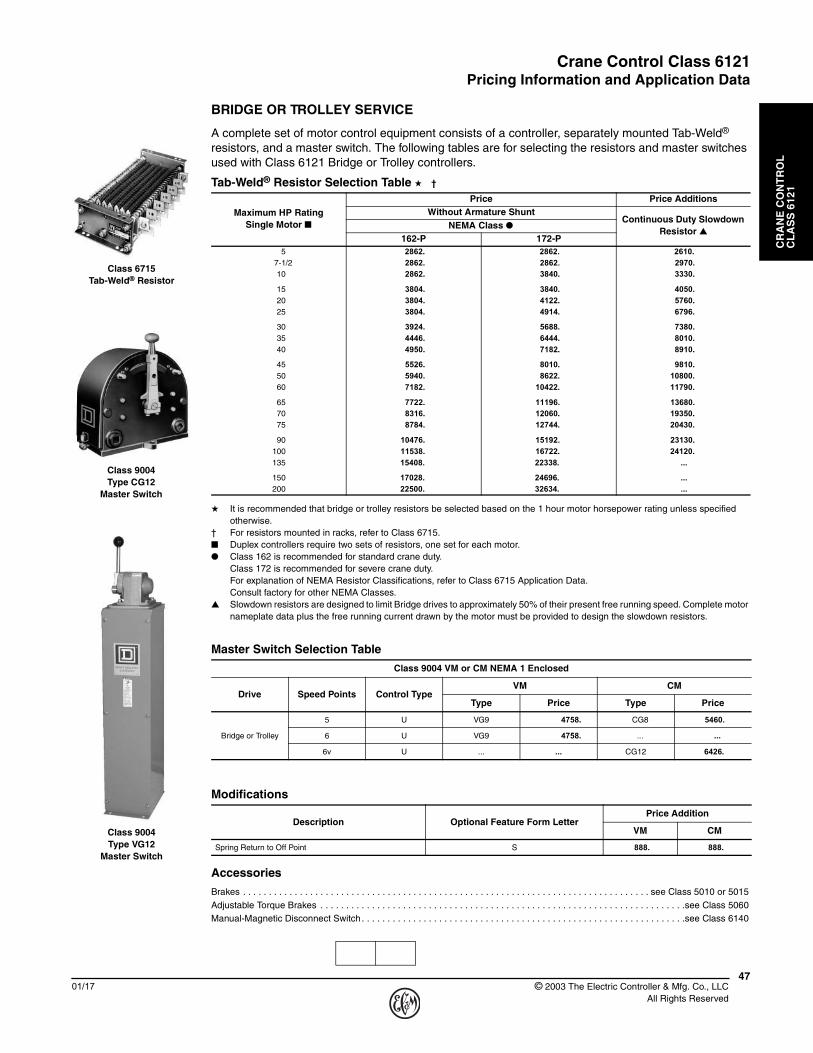
Class 6715Tab-Weld® Resistor
Class 9004Type CG12
Master Switch
Class 9004Type VG12
Master Switch
Crane Control Class 6121Frontline® DC Crane Control
CR
AN
E C
ON
TR
OL
C
LA
SS
612
1
© 2003 The Electric Controller & Mfg. Co., LLC All Rights Reserved
4601/17
GENERAL INFORMATION AND PRICING
Bridge or Trolley Service
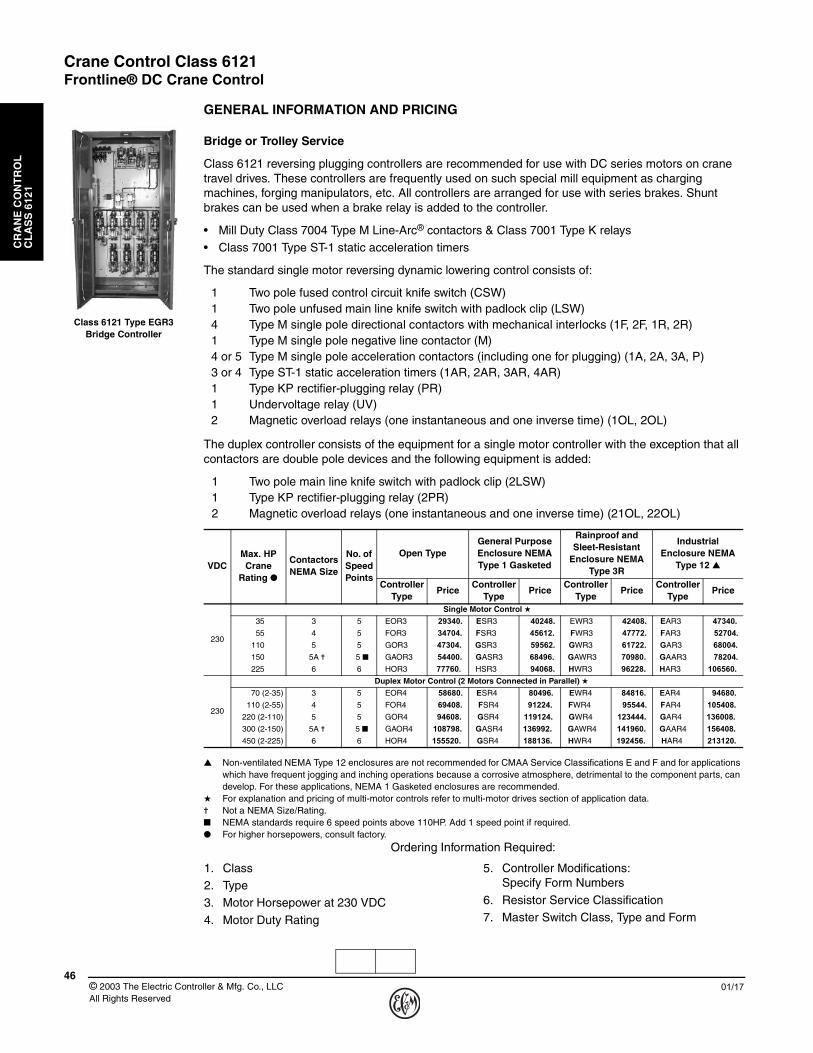
Class 6121 reversing plugging controllers are recommended for use with DC series motors on crane travel drives. These controllers are frequently used on such special mill equipment as charging machines, forging manipulators, etc. All controllers are arranged for use with series brakes. Shunt brakes can be used when a brake relay is added to the controller.
• Mill Duty Class 7004 Type M Line-Arc® contactors & Class 7001 Type K relays• Class 7001 Type ST-1 static acceleration timers
The standard single motor reversing dynamic lowering control consists of:
1 Two pole fused control circuit knife switch (CSW)1 Two pole unfused main line knife switch with padlock clip (LSW)4 Type M single pole directional contactors with mechanical interlocks (1F, 2F, 1R, 2R)1 Type M single pole negative line contactor (M)4 or 5 Type M single pole acceleration contactors (including one for plugging) (1A, 2A, 3A, P)3 or 4 Type ST-1 static acceleration timers (1AR, 2AR, 3AR, 4AR)1 Type KP rectifier-plugging relay (PR)1 Undervoltage relay (UV)2 Magnetic overload relays (one instantaneous and one inverse time) (1OL, 2OL)
The duplex controller consists of the equipment for a single motor controller with the exception that all contactors are double pole devices and the following equipment is added:
1 Two pole main line knife switch with padlock clip (2LSW)1 Type KP rectifier-plugging relay (2PR)2 Magnetic overload relays (one instantaneous and one inverse time) (21OL, 22OL)
▲ Non-ventilated NEMA Type 12 enclosures are not recommended for CMAA Service Classifications E and F and for applications which have frequent jogging and inching operations because a corrosive atmosphere, detrimental to the component parts, can develop. For these applications, NEMA 1 Gasketed enclosures are recommended.
★ For explanation and pricing of multi-motor controls refer to multi-motor drives section of application data.✝ Not a NEMA Size/Rating.■ NEMA standards require 6 speed points above 110HP. Add 1 speed point if required.● For higher horsepowers, consult factory.
Ordering Information Required:
VDCMax. HP Crane
Rating ●
Contactors NEMA Size
No. of Speed Points
Open TypeGeneral Purpose Enclosure NEMA Type 1 Gasketed
Rainproof and Sleet-Resistant
Enclosure NEMA Type 3R
Industrial Enclosure NEMA
Type 12 ▲
Controller Type
PriceController
TypePrice
Controller Type
PriceController
TypePrice
230
Single Motor Control ★
35 3 5 EOR3 29340. ESR3 40248. EWR3 42408. EAR3 47340.
55 4 5 FOR3 34704. FSR3 45612. FWR3 47772. FAR3 52704.
110 5 5 GOR3 47304. GSR3 59562. GWR3 61722. GAR3 68004.
150 5A ✝ 5 ■ GAOR3 54400. GASR3 68496. GAWR3 70980. GAAR3 78204.
225 6 6 HOR3 77760. HSR3 94068. HWR3 96228. HAR3 106560.
230
Duplex Motor Control (2 Motors Connected in Parallel) ★
70 (2-35) 3 5 EOR4 58680. ESR4 80496. EWR4 84816. EAR4 94680.
110 (2-55) 4 5 FOR4 69408. FSR4 91224. FWR4 95544. FAR4 105408.
220 (2-110) 5 5 GOR4 94608. GSR4 119124. GWR4 123444. GAR4 136008.
300 (2-150) 5A ✝ 5 ■ GAOR4 108798. GASR4 136992. GAWR4 141960. GAAR4 156408.
450 (2-225) 6 6 HOR4 155520. GSR4 188136. HWR4 192456. HAR4 213120.
1. Class2. Type 3. Motor Horsepower at 230 VDC
4. Motor Duty Rating
5. Controller Modifications:Specify Form Numbers
6. Resistor Service Classification7. Master Switch Class, Type and Form
Class 6121 Type EGR3 Bridge Controller
Crane Control Class 6121Pricing Information and Application Data
CR
AN
E C
ON
TR
OL
C
LA
SS
612
1
4701/17 © 2003 The Electric Controller & Mfg. Co., LLC
All Rights Reserved
BRIDGE OR TROLLEY SERVICE
A complete set of motor control equipment consists of a controller, separately mounted Tab-Weld® resistors, and a master switch. The following tables are for selecting the resistors and master switches used with Class 6121 Bridge or Trolley controllers.
★ It is recommended that bridge or trolley resistors be selected based on the 1 hour motor horsepower rating unless specified otherwise.
† For resistors mounted in racks, refer to Class 6715.■ Duplex controllers require two sets of resistors, one set for each motor.● Class 162 is recommended for standard crane duty.
Class 172 is recommended for severe crane duty.For explanation of NEMA Resistor Classifications, refer to Class 6715 Application Data. Consult factory for other NEMA Classes.
▲ Slowdown resistors are designed to limit Bridge drives to approximately 50% of their present free running speed. Complete motor nameplate data plus the free running current drawn by the motor must be provided to design the slowdown resistors.
Accessories
Brakes . . . . . . . . . . . . . . . . . . . . . . . . . . . . . . . . . . . . . . . . . . . . . . . . . . . . . . . . . . . . . . . . . . . . . . . . . . . . . . . see Class 5010 or 5015
Adjustable Torque Brakes . . . . . . . . . . . . . . . . . . . . . . . . . . . . . . . . . . . . . . . . . . . . . . . . . . . . . . . . . . . . . . . . . . . . . . .see Class 5060Manual-Magnetic Disconnect Switch . . . . . . . . . . . . . . . . . . . . . . . . . . . . . . . . . . . . . . . . . . . . . . . . . . . . . . . . . . . . . . .see Class 6140
Tab-Weld® Resistor Selection Table ★ †
Maximum HP Rating Single Motor ■
Price Price AdditionsWithout Armature Shunt
Continuous Duty Slowdown Resistor ▲
NEMA Class ●162-P 172-P
5 2862. 2862. 2610.7-1/2 2862. 2862. 2970.10 2862. 3840. 3330.
15 3804. 3840. 4050.20 3804. 4122. 5760.25 3804. 4914. 6796.
30 3924. 5688. 7380.35 4446. 6444. 8010.40 4950. 7182. 8910.
45 5526. 8010. 9810.50 5940. 8622. 10800.60 7182. 10422. 11790.
65 7722. 11196. 13680.70 8316. 12060. 19350.75 8784. 12744. 20430.
90 10476. 15192. 23130.100 11538. 16722. 24120.135 15408. 22338. ...
150 17028. 24696. ...200 22500. 32634. ...
Master Switch Selection Table
Class 9004 VM or CM NEMA 1 Enclosed
Drive Speed Points Control TypeVM CM
Type Price Type Price
Bridge or Trolley
5 U VG9 4758. CG8 5460.
6 U VG9 4758. ... ...
6v U ... ... CG12 6426.
Modifications
Description Optional Feature Form LetterPrice Addition
VM CM
Spring Return to Off Point S 888. 888.
Class 6715Tab-Weld® Resistor
Class 9004Type CG12
Master Switch
Class 9004Type VG12
Master Switch
Crane Control Class 6121Pricing Information and Application Data
CR
AN
E C
ON
TR
OL
C
LA
SS
612
1
© 2003 The Electric Controller & Mfg. Co., LLC All Rights Reserved
4801/17
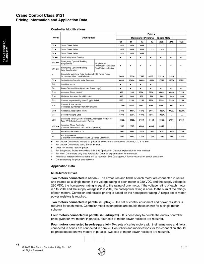
■ For Duplex Controllers multiply all prices by two with the exceptions of forms, D7, B10, B11.★ For Duplex Controllers using Series Brakes.● Does not include resistor prices.▲ For Bridge and Trolley controllers only. See Application Data for explanation of form number.❒ For Hoist Controllers only. See Application Data for explanation of form number.✝ Additional master switch contacts will be required. See Catalog 9004 for correct master switch and price.◆ Consult factory for price and delivery.
Application Data
Multi-Motor Drives
Two motors connected in series – The armatures and fields of each motor are connected in series and treated as a single motor. If the voltage rating of each motor is 230 VDC and the supply voltage is 230 VDC, the horsepower rating is equal to the rating of one motor. If the voltage rating of each motor is 115 VDC and the supply voltage is 230 VDC, the horsepower rating is equal to the sum of the ratings of both motors. Controller and resistor pricing is based on the horsepower rating. A single set of motor power resistors is required.
Two motors connected in parallel (Duplex) – One set of control equipment and power resistors is required for each motor. Controller modification prices are double those shown for a single motor scheme.
Four motors connected in parallel (Quadruplex) – It is necessary to double the duplex controller price given for two motors in parallel. Four sets of motor power resistors are required.
Four motors connected in series-parallel – Two sets of series motors with their armatures and fields connected in series are connected in parallel. Controllers and modifications for this connection should be priced based on two motors in parallel. Two sets of motor power resistors are required.
Controller Modifications
Form Description
Price ■
Maximum HP Rating — Single Motor
35 55 110 150 225 275 500
B1 ▲ Shunt Brake Relay 3312. 3312. 3312. 3312. 3312. ... ...
B3 ▲ Shunt Brake Relay 3312. 3312. 3312. 3312. 3312. ... ...
B4 ▲ Shunt Brake Relay 3312. 3312. 3312. ... ... ... ... ...
B9 ▲● Service Dynamic Braking ◆ ◆ ◆ ◆ ◆ ◆ ◆
B10 ▲●Emergency Dynamic Braking, Single Point Single Motor
Two Motors in ParallelTwo Motors in Series
◆ ◆ ◆ ◆ ◆ ◆ ◆
B11 ▲●Emergency Dynamic Braking, Auto Deceleration
D1Substitute Main Line Knife Switch with DC Rated Fuses for Unfused Main Line Knife Switch 5640. 6556. 7546. 8176. 11926. 13320. ... .
D7 ★ Series Brake Transfer Knife Switches 6408. 10404. 14688. 14694. 27072. 29536. 33792.
E19 Low Headroom ◆ ◆ ◆ ◆ ... ... ...
G8 Power Terminal Board (Includes Power Lugs) ◆ ◆ ◆ ◆ ◆ ◆ ◆
G15 Ammeter Shunt, 100MV 936. 1260. 3024. 3226. 4860. 4860. 7128.
G16 Miniature Ammeter Panel Mounted 900. 900. 900. 900. 900. 900. 900.
G22 Cabinet Inspection Light and Toggle Switch 2250. 2250. 2250. 2250. 2250. 2250. 2250.
H18Cabinet Space HeaterControlled by Interlock from M Contactor 1980. 1980. 1980. 1980. 1980. 1980. 1980.
M3 ✝ Additional Acceleration Point 3492. 4104. 5472. 6144. 8334. 9720. 16308.
M4 Second Plugging Step 4392. 5004. 6372. 7044. 9234. ... ...
M24Substitute Type SSI Time Current Acceleration Module for Type ST-1 Static Acceleration Timers 3150. 3150. 3150. 3150. 3150. 3150. 3150.
M52 ▲●Armature Shunt Contactor (Controls Slowdown for Floor/Cab Operation)
2106. 2718. 4086. 4686. 6948. ... ...
R1 ❒ Auto-Stop Rectifier Circuit 2490. 2490. 2820. 2820. 3736. 3736. 3736.
Y17Arc Suppressors (Required on Pendant and Radio Operated Controllers)
3240. 3240. 3240. 3240. 3240. 3240. 3240.

Crane Control Class 6121Controller Modifications
CR
AN
E C
ON
TR
OL
C
LA
SS
612
1
4901/17 © 2003 The Electric Controller & Mfg. Co., LLC
All Rights Reserved
Special Panel Construction
Several types of factory assembled and unitized constructions are available. Consult factory for price and delivery.
Standard controllers come equipped with the components listed. Special features to be added to standard controllers are identified by Form number. Most of these modifications are self-explanatory. Others, however, require some additional explanation.
Forms B1, B3, and B4 cover various shunt brake relay applications. These modifications are for Bridge and Trolley controllers only and in each case a double-pole, 25-ampere brake relay is supplied. The three modifications differ from each other in the way the relay is wired and controlled. Each is as follows:
B1: Relay connected in parallel with main (M) contactor coil. With this arrangement, the shunt brake will set whenever the master switch is moved to the off point.
B3: Relay controlled from external push button, foot switch, etc. This arrangement allows the shunt brake to be manually applied by the crane operator whenever necessary.
B4: Relay connected in parallel with undervoltage relay. The arrangement allows the shunt brake to set only when the main disconnect for the crane is opened or upon power failure.
Form B9, Service dynamic braking, is used for decelerating travel drives under normal operation. Service dynamic braking is occasionally used in place of plugging on a travel drive. The common arrangement is to use an initiating switch in conjunction with the electric adjustable torque or hydraulic brake pedal such that initial depression of the brake pedal provides service dynamic braking and further depression actuates the adjustable torque or hydraulic brake. Service dynamic braking assists the adjustable torque or hydraulic brake.
Form B10 covers emergency dynamic braking. Emergency dynamic braking is used to decelerate crane travel drives, such as high speed bridge drives and manned trolleys and is automatically applied upon power failure or when an overload relay trips. Emergency dynamic braking provides a simple, reliable means for braking to a stop bridge drives of cranes, or manned trolleys of ore and coal bridges, etc. Emergency dynamic braking is applied in about 1/5 the time required to set a shunt brake. The motors are converted to self-excited generators to provide retarding torque. Braking is not dependent on an outside source of power. The circuits for single step emergency dynamic braking are shown for the various motor connections.
INITIATINGCONTACT
DB
RE
S
1R
2F2R
TF
1F
3A P2A 1A
M
+ PR
ITE
MASTER SWITCH
–+
M
DB
TF
TF
DB
P 2F 1R
LSW2OL
INST
1OL
SERIESFIELD
R5ARM
R1ACCEL RES
LSWR4 R2R3
DB
Service Dynamic Braking for Single Series Motor

Crane Control Class 6121Controller Modifications
CR
AN
E C
ON
TR
OL
C
LA
SS
612
1
© 2003 The Electric Controller & Mfg. Co., LLC All Rights Reserved
5001/17
Emergency Dynamic Braking For A Single Motor – The motor is connected as self-excited generator by using a silicon rectifier bridge around the motor series field. Braking is equally effective in each direction.
Emergency Dynamic Braking For Two Motors Connected In Series – The same circuit as for a single motor is used. The armatures and fields of the two motors are permanently connected in series and are treated as a single motor.
Emergency Dynamic Braking For Two Motors Connected In Parallel – The circuit shows the simple arrangement whereby the fields and the armatures of the two series motors are cross-connected to insure self-excitation for positive emergency dynamic braking from either direction of travel. Two sets of double-pole dynamic braking contactors are used.
C1+PR
1R
2R 2F
1F 3A P2A 1A
M
ITE
RES
SS
–+ LSW
2OL
INST
1OL
SERIES
(IF USED)
SERIESFIELD BRAKE
R5ARM
VR
R1ACCEL RES
LSWR4 R3 R2
R7R6DYN BRK'G RES
2DB
1DB
Emergency Dynamic Braking for Single Motor
1R
1R
2R
2R
2F
2F
1F
1F
M
M
ITE
ITE
–+ LSW
12OL
22OL
INST
INST
11OL
21OL
SERIES
SERIES
FIELD
FIELD
ARM
ARM
VR
ACCEL RES
ACCEL RES
LSW
DYN BRK'G RES
DYN BRK'G RES
3DB
4DB
2DB
1DB
Emergency Dynamic Braking for 2 Motors in Parallel

Crane Control Class 6121Controller Modifications
CR
AN
E C
ON
TR
OL
C
LA
SS
612
1
5101/17 © 2003 The Electric Controller & Mfg. Co., LLC
All Rights Reserved
Emergency Dynamic Braking For Four Motor Drives – For four motors connected in parallel, two sets of cross-connected motors are connected in parallel to provide dynamic braking for all four motors. For this motor connection, the controller modification is priced by doubling the price given for two motors in parallel.
When four motors are connected in series parallel, that is, when two sets of motors with their armatures and fields connected in series are connected in parallel, emergency dynamic braking should be priced based on the controller modification for two motors connected in parallel.
Form B11 covers graduated emergency dynamic braking with automatic deceleration. The automatic deceleration provides a faster stop than single step deceleration from high speed without wheel slippage.
Graduated Emergency Dynamic Braking with Automatic Deceleration for a Single Motor – An additional voltage relay (2VR) and a spring closed contactor (3DB) with its main contacts shorting out a portion of the dynamic braking resistor are added to the circuit for single step emergency dynamic braking. The two voltage relays (1VR and 2VR) are used to insure proper operation of the 3DB contactor. The generated armature voltage keeps the 3DB contactor energized until the motor speed is decreased sufficiently to provide a smooth deceleration. When the 3DB contactor closes, the value of the dynamic braking resistance is decreased, and increased braking torque is provided to stop the drive.
1VR2VR
3DB
1VR
2VR1DB
2sec. T.C.
1R
2R 2F
1F 4A P3A 2A 1A
M
RES
+PR
ITE
–+ LSW
2OL
INST
1OLSERIESFIELD
R6ARM
R1ACCEL RES
LSWR2R3R4R5
R8R7DYN BRK'G RES
3DB
2DB
1DB
Graduated Emergency Dynamic Braking with Automatic Deceleration for a Single Motor.

Crane Control Class 6121Controller Modifications
CR
AN
E C
ON
TR
OL
C
LA
SS
612
1
© 2003 The Electric Controller & Mfg. Co., LLC All Rights Reserved
5201/17
Graduated Emergency Dynamic Braking with Automatic Deceleration for Multi-Motor Drives –For two motors connected in series, the fields of each motor are connected in series inside the rectifier bridge and are treated as a single motor.
The circuit for two motors connected in parallel is essentially the same as that for two motors in parallel with single step dynamic braking except for the addition of two voltage relays, 1VR and 2VR, and two normally closed contactors, 5DB and 6DB. The voltage relays and the normally closed contactors are operated based on the generated armature voltage of one motor, but control the braking of both motors. The two contactors are adjusted to reclose together as the motors decelerate. This reclosure shorts out part of the dynamic braking resistor, maintaining deceleration torque.
For Quadruplex connections where four motors are connected in parallel, it is necessary to double the controller modification price shown for two motors in parallel.
For four motors used in a series-parallel connection, graduated emergency dynamic braking should be priced based on the controller modification price for two motors connected in parallel.
Form D7 lists series brake transfer knife switches for use on duplex controllers. For single motor operation, these knife switches connect both series brakes in series with one motor to permit operating the drive without having to manually release one brake.
Form M4 lists a second plugging step. An additional plugging relay (2PR) and an additional plugging contactor (2P) are supplied. A second plugging step is recommended for heavy cranes, such as ladle crane bridge drives or high speed cranes such as ore bridge trolleys or high speed bridge drives. Two steps of plugging provide faster slowdown without spinning the wheels.
Form M24 provides time delay acceleration proportional to motor current.
+ -
1VR
2VR
5DB
6DB
1VR
1VR
RES1
RES3
ARES
ARES
2VR
2VR
2DB
3DB
1R8
1R7
2R7
5DB
6DB
1R6
2R62R8
4DB
1DB
4AR
MOV
RECT
(1.2 SEC)
11R
12R
11R
12F
12F12R
11F
11FP
P
3A
3A
2A4A
4A
DB RES #1
DB RES #2
2A
1A
1A
M
M
2PR
1PR
+
+
+
-
1LSW
INST.
11OL
12OL
22OL
123 124
1A1
2A1
1A2
2A2
1S1
2S1SERIES
SERIES
#2
#1
FIELD
FIELD
ARM
ARM
#1
#2
#1 ACCEL RES
#2 ACCEL RES
2LSW
1LSW
21
INST.
OL
2LSW2S2
1S2
121
1R1
2R1
1R2
2R2
1R3
2R3
1R41R5
2R42R5
1R6
2R6I.T.E
I.T.E
120
Graduated Emergency Dynamic Braking for Two Motors in Parallel
Crane Control Class 6121Application Data
CR
AN
E C
ON
TR
OL
C
LA
SS
612
1
5301/17 © 2003 The Electric Controller & Mfg. Co., LLC
All Rights Reserved
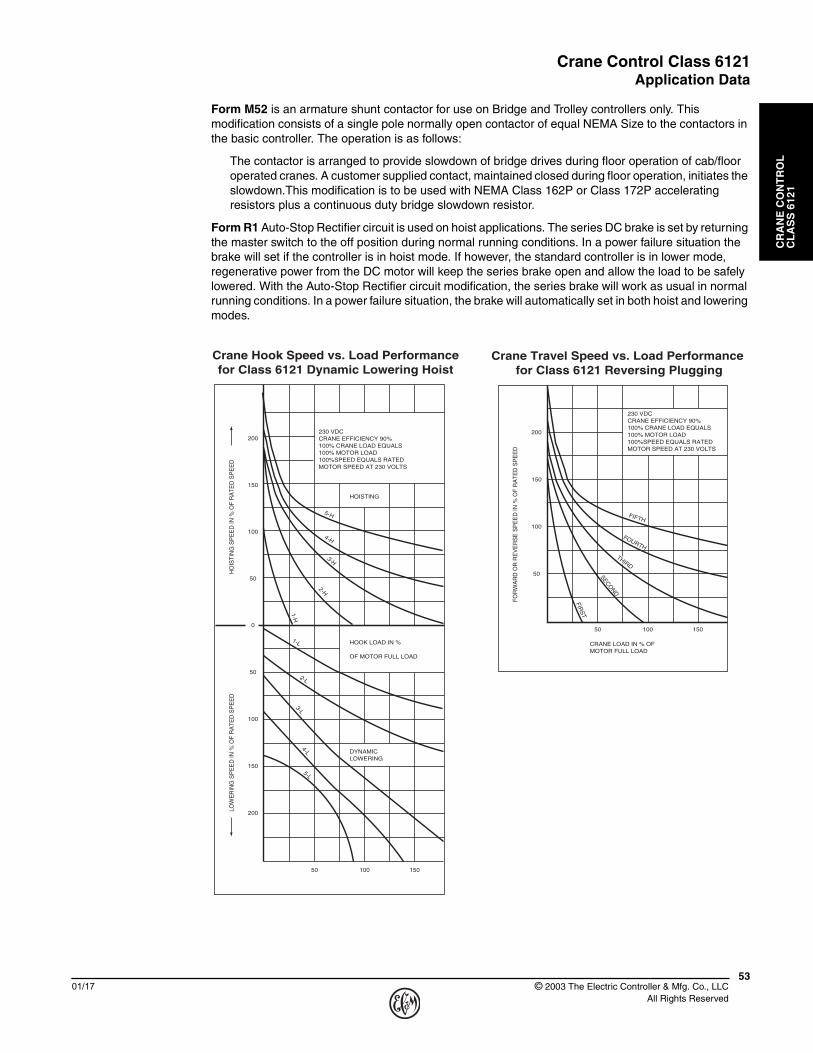
Form M52 is an armature shunt contactor for use on Bridge and Trolley controllers only. This modification consists of a single pole normally open contactor of equal NEMA Size to the contactors in the basic controller. The operation is as follows:
The contactor is arranged to provide slowdown of bridge drives during floor operation of cab/floor operated cranes. A customer supplied contact, maintained closed during floor operation, initiates the slowdown.This modification is to be used with NEMA Class 162P or Class 172P accelerating resistors plus a continuous duty bridge slowdown resistor.
Form R1 Auto-Stop Rectifier circuit is used on hoist applications. The series DC brake is set by returning the master switch to the off position during normal running conditions. In a power failure situation the brake will set if the controller is in hoist mode. If however, the standard controller is in lower mode, regenerative power from the DC motor will keep the series brake open and allow the load to be safely lowered. With the Auto-Stop Rectifier circuit modification, the series brake will work as usual in normal running conditions. In a power failure situation, the brake will automatically set in both hoist and lowering modes.
0
50
100
150
200
50
100
150
200
1-L
5-H
4-H
3-H
2-H
1-H
2-L
3-L4-L
5-L
200
150
100
50
50 100 150
50 100 150
FIFTH
FOURTH
THIRD
SECOND
FIRS
T
230 VDCCRANE EFFICIENCY 90%100% CRANE LOAD EQUALS100% MOTOR LOAD100%SPEED EQUALS RATEDMOTOR SPEED AT 230 VOLTS
CRANE LOAD IN % OFMOTOR FULL LOAD
FOR
WA
RD
OR
RE
VE
RS
E S
PE
ED
IN %
OF
RA
TED
SP
EE
D
Crane Travel Speed vs. Load Performance for Class 6121 Reversing Plugging
Crane Hook Speed vs. Load Performancefor Class 6121 Dynamic Lowering Hoist
LOW
ER
ING
SP
EE
D IN
% O
F R
ATE
D S
PE
ED
HO
ISTI
NG
SP
EE
D IN
% O
F R
ATE
D S
PE
ED
HOOK LOAD IN %
OF MOTOR FULL LOAD
HOISTING
DYNAMICLOWERING
230 VDCCRANE EFFICIENCY 90%100% CRANE LOAD EQUALS100% MOTOR LOAD100%SPEED EQUALS RATEDMOTOR SPEED AT 230 VOLTS
Crane Control Class 6121Wiring Diagrams
CR
AN
E C
ON
TR
OL
C
LA
SS
612
1
© 2003 The Electric Controller & Mfg. Co., LLC All Rights Reserved
5401/17
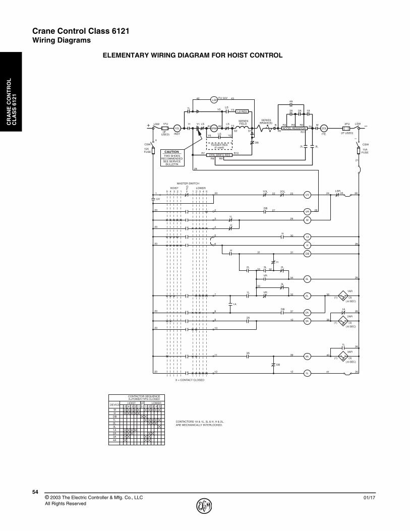
ELEMENTARY WIRING DIAGRAM FOR HOIST CONTROL
42
Y5
A2A1H Y1 LS LS
(IF USED)(IFUSED)
1FU 2FU
OFF12345 1 2 3 4 5
CONTACTOR SEQUENCEX=POWER TIPS CLOSED
HOIST LOWER
4A
MH
DB1L2L3L1A2A3A
DEVICE
20
29
CAUTION
UV
VR
M
1A
H
DB
3L
2L
2A
3A
4A
1L
LSR2OL1OL
1L
H
2L
3L
VR
1A
DB
H
H
2L 3L
VR
1L
DB
2A
3A
1L
(1) (3)
3AR
(1) (3)
2AR
(1) (3)
1AR
H
1A
DB
1
2
3
4
5
6
31 31
27
30
22 23
28
24
28
21
33
33
32
34
7
8
9
35 36
38
37
10
10
11
12
39
12
40
41
X = CONTACT CLOSED
20
20
20
20
20
20
TWO SHOESRECOMMENDED
SEE SERVICEBULLETIN
ARM
SERIESFIELD
1OL
INST
1LLS RES
LSY3
Y4
LSRPU 55V
LSY6 Y2
DB
ACCEL RESISTOR
R7 R10
R9R8
SERIESBRAKE(S)
B
R5
DYN. BRK'G RES
TEASER RES(if used)
R1R2R3R4
4A
3A 2A 1A
M
3L2L
2OL
ITE
43
UV
5 4 3 2 1 1 2 3 4 5HOIST LOWERO
FF
MASTER SWITCH
(.6 SEC)
(.6 SEC)
(.6 SEC)
S1S2 R11
LSW
+CSW
FUSE15A
LSW
–
2625
26
26
26
26
26
FUSE15A
CSW
CONTACTORS 1A & 1L, 3L & H, H & 2L,ARE MECHANICALLY INTERLOCKED.
–+

Crane Control Class 6121Wiring Diagrams
CR
AN
E C
ON
TR
OL
C
LA
SS
612
1
5501/17 © 2003 The Electric Controller & Mfg. Co., LLC
All Rights Reserved
ELEMENTARY WIRING DIAGRAM FOR BRIDGE OR TROLLEY CONTROL
CONTACTORS 1R & 1F, 1F & 2R, 2R & 2FARE MECHANICALLY INTERLOCKED.
5 4 3 2 1 1 2 3 4 5
1F2F1R2RMP
1A2A3A
X= POWER TIPS CLOSED
REVERSE FORWARDOFF
CONTACTOR SEQUENCE
DEVICE
1R
2F
1A2A P3A
R1 R5
R4 R2 R3
ACCEL RESISTOR
SERIESFIELD
1OL
INST
1F 1R
2F2RA2
A1
41+
42
S2S1 M 2OL
ITE
LSW
(IF USED)
1FU
ARM
PR
LSW
(IF USED)
2FU
+ –
36 37
35
33
31
40
29
34
32
23
25
27 40
40
40
40
20
2
3
4
5
6
7
8
20
1
20
20
20
FUSE15A
CSW
FUSE15A
CSW
4 55 3 2 1 1 2 3 4REVERSE FORWARD
FFO
MASTER SWITCH
UV
1R
1F
2R
2F
P
M
3A
2A
1A
2OL 10L
2F
1R
PR
2A
1A
P
M
21
30
22
24
28
26
UV
X = CONTACT CLOSED
(3)
(3)
(3)
(1)
(1)
(1)
(.6 SEC)
(.6 SEC)
(.6 SEC)
3AR
2AR
1AR
(3)
(3)
(3)
(1)
(1)
SERIESBRAKE
(IF USED)+ –

Crane Control Class 6121Application Data
CR
AN
E C
ON
TR
OL
C
LA
SS
612
1
© 2003 The Electric Controller & Mfg. Co., LLC All Rights Reserved
5601/17
APPROXIMATE NUMBER OF SEPARATELY MOUNTED STANDARD CLASS 6715 TAB-WELD® RESISTOR SECTIONS FURNISHED WITH CLASS 6121 CONTROLLERS
This tabulation is based on Square D resistor designs for use with Class 6121 controllers only. This tabulation is for typical drive loading and may vary for any specific application.
▲ Does not include YOUNGSTOWN® power limit switch resistor. Refer to Class 6170.● Does not include acceleration resistor.
Standard Class 6715 Tab-Weld® Resistor Section
Maximum HP Rating
Single Motor (230V)
Hoist ▲ Bridge Or Trolley
162-DL 172-DL Teaser FieldWithout Armature Shunt Continuous
Duty Slowdown Resistor ●162-P 172-P
5 5 5 3 1 1 17-1/2 4 4 2 1 1 1
10 3 3 2 1 2 1
15 3 3 1 2 2 220 3 4 1 2 3 325 4 6 1 2 3 4
30 5 7 1 3 3 435 6 8 1 3 4 540 6 10 1 3 4 5
45 8 11 2 4 5 650 8 11 2 4 6 660 10 15 2 4 6 7
65 11 15 2 4 6 870 11 14 2 5 7 1175 11 17 2 6 7 11
90 13 17 2 6 9 13100 16 19 2 6 9 13135 20 30 4 9 12 ...
150 21 28 4 10 12 ...200 28 38 5 13 19 ...250 34 44 7 16 21 ...
275 43 53 8 18 24 ...300 43 53 8 19 26 ...325 43 56 8 20 28 ...
375 48 62 8 23 32 ...500 75 97 14 32 44 ...
Dual Dimensions inchesmmWeight – 35 lbs (16 kg)
6152
6152
25635
0.7519
0.7519
26.5673
2.564
2.564
2.1354
0.3810
(4) 3/8 DIA.MTG. HOLE
11279
Crane Control Class 6121Application Data
CR
AN
E C
ON
TR
OL
C
LA
SS
612
1
5701/17 © 2003 The Electric Controller & Mfg. Co., LLC
All Rights Reserved
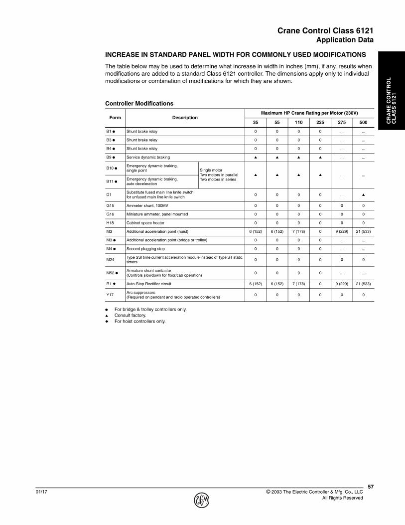
INCREASE IN STANDARD PANEL WIDTH FOR COMMONLY USED MODIFICATIONS
The table below may be used to determine what increase in width in inches (mm), if any, results when modifications are added to a standard Class 6121 controller. The dimensions apply only to individual modifications or combination of modifications for which they are shown.
● For bridge & trolley controllers only.▲ Consult factory.◆ For hoist controllers only.
Controller Modifications
Form DescriptionMaximum HP Crane Rating per Motor (230V)
35 55 110 225 275 500
B1 ● Shunt brake relay 0 0 0 0 ... ...
B3 ● Shunt brake relay 0 0 0 0 ... ...
B4 ● Shunt brake relay 0 0 0 0 ... ...
B9 ● Service dynamic braking ▲ ▲ ▲ ▲ ... ...
B10 ●Emergency dynamic braking, single point Single motor
Two motors in parallelTwo motors in series
▲ ▲ ▲ ▲ ... ...
B11 ●Emergency dynamic braking, auto deceleration
D1Substitute fused main line knife switch for unfused main line knife switch
0 0 0 0 ... ▲
G15 Ammeter shunt, 100MV 0 0 0 0 0 0
G16 Miniature ammeter, panel mounted 0 0 0 0 0 0
H18 Cabinet space heater 0 0 0 0 0 0
M3 Additional acceleration point (hoist) 6 (152) 6 (152) 7 (178) 0 9 (229) 21 (533)
M3 ● Additional acceleration point (bridge or trolley) 0 0 0 0 ... ...
M4 ● Second plugging step 0 0 0 0 ... ...
M24Type SSI time current acceleration module instead of Type ST static timers
0 0 0 0 0 0
M52 ●Armature shunt contactor (Controls slowdown for floor/cab operation)
0 0 0 0 ... ...
R1 ◆ Auto-Stop Rectifier circuit 6 (152) 6 (152) 7 (178) 0 9 (229) 21 (533)
Y17Arc suppressors (Required on pendant and radio operated controllers)
0 0 0 0 0 0

Crane Control Class 6121Approximate Dimensions and Weights
CR
AN
E C
ON
TR
OL
C
LA
SS
612
1
© 2003 The Electric Controller & Mfg. Co., LLC All Rights Reserved
5801/17
SINGLE MOTOR CONTROL STANDARD FLOOR MOUNTED CONTROLLERS
▲ Dimensions are for a 5 speed point controller. NEMA standards require 6 speeds above 110HP. Refer to Form M3 for increase in panel width.
Drive Maximum HP (230V)
Open Type Enclosed Type
H W C Net Weight lbs (kg) H W D Net Weight
lbs (kg)
Hoist
3568
172733838
12305
500 (227.3)68
172733
83815
381700 (318.2)
5568
172733838
12305
500 (227.3)68
172733
83815
381700 (318.2)
150 ▲78
198138965
15381
700 (318.2)78
198138
96517
432900 (409.1)
27572
182972
182921
5331300 (590.9)
721829
721829
23584
1800 (818.2)
50090
228699
251525
6352600 (1181.8)
902286
992515
27686
3700 (1681.8)
Bridge or
Trolley
3568
172733838
12305
500 (227.3)68
172733
83815
381700 (318.2)
5568
172733838
12305
500 (227.3)68
172733
83815
381700 (318.2)
150 ▲78
198138965
15381
700 (318.2)78
198138
96517
432900 (409.1)
22572
182972
182921
5331200 (545.5)
721829
721829
23584
1500 (681.8)
Dual Dimensions inchesmm
––
++
INCOMINGLINE TERMINAL
W
4 4 3
4
C
H
W
H
W+
2.5
D
0.5
D+REQUIRED
CLEARANCE TO NEAREST
CONDUCTING SURFACE
CONTROL TERMINAL
BOARD
CONTROL TERMINAL
BOARD
0.62516
MTG. BOLTHOLES
251
64
376
13
102 102 76
102
0.256
Open Type Enclosed Type

Crane Control Class 6121Approximate Dimensions and Weights
CR
AN
E C
ON
TR
OL
C
LA
SS
612
1
5901/17 © 2003 The Electric Controller & Mfg. Co., LLC
All Rights Reserved
DUPLEX MOTOR CONTROL STANDARD FLOOR MOUNTED CONTROLLERS
◆ Two control panels are required. Dimensions are given for each except:The Size 5A hoist, which has one panel 56" (1422 mm) wide and the second at 45" (1143 mm) wide.The Size 6 and 6A hoists, which have one panel 72" (1829 mm) wide, and one at 78" (1981 mm) wide.
Drive Maximum HP (230V)
Open Type Enclosed Type
H W C Net Weight lbs (kg) H W D Net Weight
lbs (kg)
Hoist
70 (2-35)68
172766
167612
3051000 (453.6)
681727
661676
15381
1000 (453.6)
110 (2-55)68
172766
167612
3051000 (453.6)
681727
661676
15381
1000 (453.6)
220 (2-110)78
198177
195615
3811400 (635.0)
781981
771956
17432
1800 (818.2)
300 (2-150)◆ 78
198156/45
1422/114315
3811100 (500.0)
781981
56/451422/1143
17432
1420 (645.5)
450 (2-225) ◆ 72
182972/78
1829/198121
5331300 (590.9)
721829
72/781829/1981
23584
1800 (818.2)
550 (2-275) ◆ 72
182972/78
1829/198121
5331300 (590.9)
721829
72/781829/1981
23584
1800 (818.2)
1000 (2-500) ◆
902286
992515
25635
2600 (1181.8)90
228699
251527
6863700 (1681.8)
Bridge or
Trolley
70 (2-35)68
172766
167612
3051000 (453.6)
681727
661676
15381
1400 (635.0)
110 (2-55)68
172766
167612
3051000 (453.6)
681727
661676
15381
1400 (635.0)
300 (2-150)78
198177
195615
3811400 (635.0)
781981
771956
17432
1800 (818.2)
450 (2-225) ◆ 72
182972
182921
5331200 (545.5)
721829
721829
23584
1800 (818.2)
Dual Dimensions inchesmm
––
++
W
C
H
W
H
W+
D
D+
REQUIRED CLEARANCE TO NEAREST
CONDUCTING SURFACE
CONTROL TERMINAL
BOARD
CONTROL TERMINAL
BOARD
4 4 3
4
2.5
0.5
0.62516
MTG. BOLTHOLES
251
64
376
13
102 102 76
102
0.256INCOMING
LINE TERMINAL
Open Type Enclosed Type

Crane Control Class 6121Rectified DC Constant Potential HWR Hoist Control
CR
AN
E C
ON
TR
OL
C
LA
SS
612
1
© 2003 The Electric Controller & Mfg. Co., LLC All Rights Reserved
6001/17
GENERAL INFORMATION AND PRICING
HWR hoist control is recommended for use with DC series motors on AC powered cranes requiring the speed range, accuracy and dependability of a DC powered crane hoist controller. Typically, 230 VDC rated motors are applied at either 230 VDC, 300 VDC, or 360 VDC.
The complete HWR Hoist Control system consists of:
1 Class 6121 DC reversing dynamic lowering controller1 Set of Class 6715 Tab-Weld® resistors1 Class 9004 Master switch
1 Rectifier power supplyConsult factory for price and delivery.
▲ For resistors mounted in racks - refer to Class 6715.● Class 162 is recommended for standard crane duty. Class 172 is recommended for severe crane duty.
For explanation of NEMA Resistor Classifications- refer to Class 6715 Application Data.a Resistor pricing based on 300 VDC rectifier output. For 360 VDC applications, consult factory.
Tab-Weld® Resistor Selection Table ▲
Maximum HP CraneRating @230 VDC
NEMA Class ●
162-DL a 172-DL a
5 11358. 15912.
7-1/2 9558. 13392.
10 9558. 13392.
15 9144. 12798.
20 10818. 15156.
25 12474. 17460.
30 14304. 19854.
35 16002. 22392.
40 17658. 24732.
45 20628. 28872.
50 22392. 31356.
60 25722. 36018.
65 27575. 38286.
70 29880. 41832.
75 31662. 44334.
90 36756. 51462.
100 40284. 56394.
135 54720. 76608.
150 59850. 83790.
200 78732. 110232.
250 101106. 141552.
275 111132. 155592.
300 119700. 167580.
325 129744. 181638.
375 147042. 205866.
Crane Control Class 6121Rectified DC Constant Potential HWR Hoist Control
CR
AN
E C
ON
TR
OL
C
LA
SS
612
1
6101/17 © 2003 The Electric Controller & Mfg. Co., LLC
All Rights Reserved
APPLICATION DATA
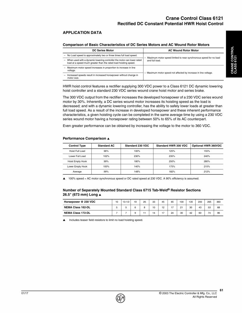
HWR hoist control features a rectifier supplying 300 VDC power to a Class 6121 DC dynamic lowering hoist controller and a standard 230 VDC series wound crane hoist motor and series brake.
The 300 VDC output from the rectifier increases the developed horsepower of a 230 VDC series wound motor by 30%. Inherently, a DC series wound motor increases its hoisting speed as the load is decreased; and with a dynamic lowering controller, has the ability to safely lower loads at greater than full load speed. As a result of the increase in developed horsepower and these inherent performance characteristics, a given hoisting cycle can be completed in the same average time by using a 230 VDC series wound motor having a horsepower rating between 50% to 65% of its AC counterpart.
Even greater performance can be obtained by increasing the voltage to the motor to 360 VDC.
▲ 100% speed = AC motor synchronous speed or DC rated speed at 230 VDC. A 90% efficiency is assumed.
▲ Includes teaser field resistors to limit no load hoisting speed.
Comparison of Basic Characteristics of DC Series Motors and AC Wound Rotor Motors
DC Series Motor AC Wound Rotor Motor
– No Load speed is approximately two or three times full load speed.– Maximum motor speed limited to near synchronous speed for no load
and full load.– When used with a dynamic lowering controller the motor can lower rated load at a speed much greater than the rated load hoisting speed.
– Maximum motor speed increases in proportion to increase in line voltage.
– Maximum motor speed not affected by increase in line voltage.– Increased speeds result in increased horsepower without change in
motor size.
Performance Comparison ▲
Control Type Standard AC Standard 230 VDC Standard HWR 300 VDC Optional HWR 360VDC
Hoist Full Load 96% 100% 125% 155%
Lower Full Load 102% 230% 235% 240%
Hoist Empty Hook 99% 180% 250% 280%
Lower Empty Hook 100% 140% 175% 215%
Average 99% 148% 182% 212%
Number of Separately Mounted Standard Class 6715 Tab-Weld® Resistor Sections 26.5" (673 mm) Long ▲
Horsepower @ 230 VDC 10 13-1/2 19 26 33 45 65 100 135 200 265 360
NEMA Class 162-DL 5 5 6 8 10 12 17 21 30 43 53 68
NEMA Class 172-DL 7 7 9 11 14 17 24 30 42 60 74 96

Crane Control Class 6121DC Mill Auxiliary Control
CR
AN
E C
ON
TR
OL
C
LA
SS
612
1
© 2003 The Electric Controller & Mfg. Co., LLC All Rights Reserved
6201/17
GENERAL INFORMATION
DC mill auxiliary controllers are recommended for use with DC series, shunt, or compound wound motors. They are frequently used on steel mill auxiliary drives such as screwdowns, tables, sideguards, shears, and similar applications. Mill auxiliary controllers can have continuous ratings as well as intermittent and they typically include one less acceleration point than crane drives.
• Mill Duty Class 7004 Type M Line-Arc® contactors & Class 7001 Type K relays• Class 7001 Type ST-1 static acceleration timers
Five basic control types are available. The equipment supplied as standard on each of these controllers is listed below:
Reversing Plugging (RP) Control
1 Two pole fused control circuit knife switch (CSW)
1 Two pole unfused main line knife switch with padlock clip (LSW)
1 Surge suppressor for motor shunt field protection (included on panels used with shunt or compound wound motors only)
4 Type M single pole directional contactors with mechanical interlocks (1F, 2F, 1R, 2R)
3 or 4 Type M single pole acceleration contactors (including one for plugging) (1A, 2A, 3A, P)
2 or 3 Type ST-1 static acceleration timers (1AR, 2AR, 3AR)
1 Type M single pole negative line contactor (M)
1 Type KP rectifier-plugging relay (PR)
1 Undervoltage relay (UV)
2 Magnetic overload relays (one instantaneous and one inverse time) (1OL, 2OL)
Reversing Plugging Dynamic Braking (RPD) Control
Includes the same equipment as the reversing plugging (RP) controller, but with the addition of:
1 Type M single pole spring-closed dynamic braking contactor (DB)
Non-Reversing (NR) Control
1 Two pole fused control circuit knife switch (CSW)
1 Two pole unfused main line knife switch with padlock clip (LSW)
1 Surge suppressor for motor shunt field protection (included on panels used with shunt or compound wound motors only)
1 Type M single pole positive line contactor (1M)
1 Type M single pole negative line contactor (2M)
2 or 3 Type M single pole acceleration contactors (1A, 2A, 3A)
2 or 3 Type ST-1 static acceleration timers (1AR, 2AR, 3AR)
1 Undervoltage relay (UV)
2 Magnetic overload relays (one instantaneous and one inverse time) (1OL, 2OL)
Non-Reversing Dynamic Braking (NRD) Control
Includes the same equipment as the non-reversing (NR) controller, but with the addition of:
1 Type M single pole spring-closed dynamic braking contactor (DB)
Consult factory for price and delivery.
Crane Control Class 6121DC Mill Auxiliary Control
CR
AN
E C
ON
TR
OL
C
LA
SS
612
1
6301/17 © 2003 The Electric Controller & Mfg. Co., LLC
All Rights Reserved
GENERAL INFORMATION
Reversing Non-Plugging Dynamic Braking (RNPD) Control
1 Two-pole fused control circuit knife (CSW)
1 Two-pole unfused main line knife switch with padlock clip (LSW)
1 Surge suppressor for motor shunt field protection (included on panels used with shunt orcompound wound motors only)
4 Type M single-pole directional contactors with mechanical interlocks (1F, 2F, 1R, 2R)
2 or 3 Type M single-pole acceleration contactors (including one for plugging) (1A, 2A, 3A)
2 or 3 Type ST-1 static acceleration timers (1AR, 2AR, 3AR)
1 Type M single-pole negative line contactor (M)
1 Type M single-pole spring-closed dynamic braking contactor (DB)
1 Type KE non-plugging relay (NP)
1 Undervoltage relay (UV)
2 Magnetic overload relays (one instantaneous and one inverse time) (1OL, 2OL)
Duplex Motor Control – 2 Motors Connected in Parallel
The duplex controller consists of the equipment for a single motor controller with the exception that all contactors are double pole devices and one additional main line knife switch and two overload relays are added to the controller.
Crane Control Class 6121
CR
AN
E C
ON
TR
OL
C
LA
SS
612
1
© 2003 The Electric Controller & Mfg. Co., LLC All Rights Reserved
6401/17