crackerbox - model boat kits props ... - · pdf file1 zipp manufacturing abox crackerbox impba...
TRANSCRIPT
1
Z I P P M A N U FA C T U R I N G
ABox Crackerbox
IMPBA / NAMBA Legal Crackerbox
A Zippkits R/C Boat
Building Instructions 2014 JMP Hobby Group LLC – Saint Paul, Indiana
www.zippkits.com
Toll Free (866) 922-ZIPP

2
The Zippkits ABox Crackerbox was developed from a very successful series of Crackerbox kits.
We made improvements and redesigns through the years.
The ABox is a culmination of all of our design tricks and is by far our best Crackerbox.
It is based on the full size APBA Crackerbox (the “A” in ABox), and retains the sweet lines of the
Crackerbox while being our easiest to build kit ever.
This new hull also performs better than all of our other Crackerbox designs, and is currently legal in all
Crackerbox racing classes.
Going fast is easy for a Crackerbox, due to its nearly flat bottom. Turning is the real issue. Most cracker boxes have to slow for the turns. Our other cracker boxes were no exception. This new design turns like it is on rails, and shows no tendency to roll or flip in the turns. We really love this new ABox!
Take the time to read this entire manual, so that you are familiar with all the buildings steps and their
proper order. Take your time; make sure you understand everything before you do it and you will be
rewarded with an impressive running hull…
Note that the pictures in this manual may be of a different boat to better illustrate a point.
This kit is not a toy. Although R/C boating is a fun and rewarding hobby, it can be dangerous if not
done with common sense and safety in mind. Just about anyone should be able to build this kit, but it
should not be operated by children without close adult supervision.
The manufacturer assumes no liability for damages or other loss in the use of this product, as we have no control over the construction or end use of this product.

3
Tools and supplies needed to build
Sanding blocks with 80 and 150 grit paper
Drill with 1/16 and 3/32 bits
Square
Flat file
Round (3/16) file
5/16 and 3/8 open end wrenches
FLAT Workbench
Hex ball drivers
Flat work surface
Medium CA glue and accelerator
Good quality 30 minute epoxy
Epoxy finishing resin or Klass Kote Epoxy
Spring clamps, paper clamps, c clamps, etc.
Razor blade or X-Acto knife
Masking tape
Waxed paper
Wood filler
Primer
Paint

4
Additional items needed to
complete
Gasoline engine
5 inch mounts (Zipp 3409)
.250 Collet for engine (Zipp 3446 or 3426)
.250 24 inch cable w/welded stub shaft (Zipp 3444)
Tuned pipe or canister muffler (check the rules)
2 channel surface radio with 1 standard and 1 heavy duty servo (100 in/oz minimum)
Throttle pushrod (Zipp 3462)
Rudder pushrod (Zipp 3463)
2 pushrod seals (Zipp 3404 or 3422)
16-24 ounce fuel tank and tubing (gasoline compatible)
.250 strut (Zipp 3421)
.250 drive dog (Zipp 3442)
670 prop (Zipp 4016)
Prop nuts (Zipp 3450)
Cable grease
Large rudder ( Zipp 3414)
3 feet large silicone tubing (Zipp 3461)
12 inch length of 11/32 brass tubing (Zipp 3453)
36 inch length of 5/16 brass tubing (Zipp 3452)
Floatation (pool noodles, foam, etc.)
Transom turn fin (Zipp3410)

5
Let’s identify the parts so that we can easily find them when needed. Mark the parts that are inside other
parts.
1/8 plywood parts:

6

7
1/4 plywood parts
Do an inventory of all the parts, to be sure that everything is there. If anything is missing or
damaged, contact us as soon as possible, so that we can get replacements to you quickly.
Work Surface
We recommend that you use a straight, flat work surface.
Minimum size would be at least 24 by 48 inches.
Your work surface should be able to take screws or nails (this eliminates the kitchen table…)
Every critical component on this hull depends on a straight, flat surface.
Do whatever it takes to get this done.
8
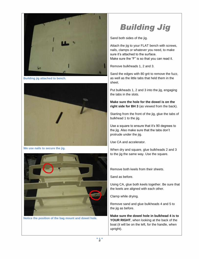
Building jig attached to bench.
We use nails to secure the jig.
Notice the position of the bag mount and dowel hole.
Building Jig
Sand both sides of the jig.
Attach the jig to your FLAT bench with screws,
nails, clamps or whatever you need, to make
sure it’s attached to the surface.
Make sure the “F” is so that you can read it.
Remove bulkheads 1, 2 and 3.
Sand the edges with 80 grit to remove the fuzz,
as well as the little tabs that held them in the
sheet.
Put bulkheads 1, 2 and 3 into the jig, engaging
the tabs in the slots.
Make sure the hole for the dowel is on the
right side for BH 3 (as viewed from the back).
Starting from the front of the jig, glue the tabs of
bulkhead 1 to the jig.
Use a square to ensure that it’s 90 degrees to
the jig. Also make sure that the tabs don’t
protrude under the jig.
Use CA and accelerator.
When dry and square, glue bulkheads 2 and 3
to the jig the same way. Use the square.
Remove both keels from their sheets.
Sand as before.
Using CA, glue both keels together. Be sure that
the keels are aligned with each other.
Clamp while drying.
Remove sand and glue bulkheads 4 and 5 to
the jig as before.
Make sure the dowel hole in bulkhead 4 is to
YOUR RIGHT, when looking at the back of the
boat (it will be on the left, for the handle, when
upright).

9
Keel halves before laminating.
Keel and engine rails installed.
Keel glued to the face of BH 1. Be sure it’s square.
Find the two ¼ ply engine rails. Sand them
smooth with 80.
Clamp a piece of wood to the back of BH 5 for
the next few steps.
Check the fit of the engine rails into bulkheads
3, 4 and 5.
One engine rail has a relief for the carb. This
goes on your left side (right side when the boat
is turned over)
If ok, glue them in (the big end goes forward).
Use 30 minute epoxy for the engine rails.
The keel should be dry by now.
Check the fit of the keel into bulkheads 1, 2 and
3.
If ok, glue it in, making sure the keel is centered
on bulkhead 1. Use a square to be sure that the
keel is in the center of bulkhead 1.
This kind of looks like a boat, doesn’t it?
Take a break, and give the glue a little while to
completely cure.
Now is the time to glue in the keel jig supports
to the front of the jig.
These keep the keel from bending or twisting as
we attach the chines.
Glue these to the jig only, not the keel.
Put several rubber bands around them to hold
the keel in place. The rubber bands should go
under the keel.
Next, we will install the chines. Make sure you
follow along closely, as these are very important
to the final shape.
Using CA, glue one of the top (closest to the
bench, remember the boat is upside down)
chines to the notch in bulkhead 5.

10
Keel jig supports. Note rubber band.
Fitting top chine in place.
Top chines meet at nose.
Be sure that the chines are glued in so that
they match the angle of the bulkhead tops.
You can lay it in the notch on bulkhead 4 while
the glue dries; just don’t glue it to 4 yet.
Hit the glue joint with accelerator. Hold it in
place for 60 seconds or so.
When you are sure the glue is cured, glue to
bulkhead 4.
Hit that with accelerator, hold for 30 seconds or
so, then move ahead to 3, then 2, then 1.
Do not glue the chine to the keel yet.
The reason for gluing, holding for a few
seconds, then moving forward is because the
shape of the chine changes as you move
forward. Doing it this way, the glue has not
completely cured, and can be “adjusted” a little,
as you bend the chine to the next bulkhead. If
you waited until each glue joint was completely
cured before moving on to the next one, the
chine would take on a straight, angular look,
instead of the smooth curve it should.
Now you get to glue yourself to the boat! Try not
to…
Using CA, put glue on the ends of the two top
chines.
Squeeze both chines together at the tip of the
keel.
Make sure that both are even, and fit into the
notch on the top of the keel.
Hit the joint with accelerator, and hold for a
minute or so.
Try not to glue your fingers to the chines! If you
do, it could be rather embarrassing to have your
wife try to free you. She will use that story for
life!
11
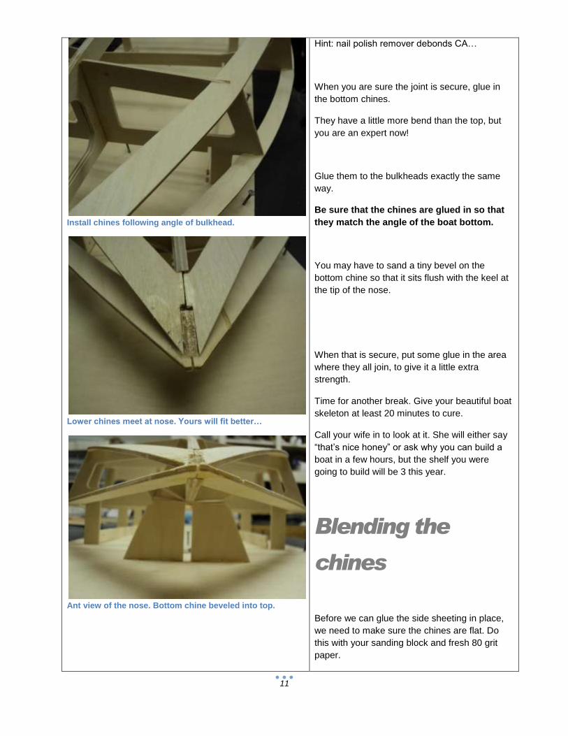
Install chines following angle of bulkhead.
Lower chines meet at nose. Yours will fit better…
Ant view of the nose. Bottom chine beveled into top.
Hint: nail polish remover debonds CA…
When you are sure the joint is secure, glue in
the bottom chines.
They have a little more bend than the top, but
you are an expert now!
Glue them to the bulkheads exactly the same
way.
Be sure that the chines are glued in so that
they match the angle of the boat bottom.
You may have to sand a tiny bevel on the
bottom chine so that it sits flush with the keel at
the tip of the nose.
When that is secure, put some glue in the area
where they all join, to give it a little extra
strength.
Time for another break. Give your beautiful boat
skeleton at least 20 minutes to cure.
Call your wife in to look at it. She will either say
“that’s nice honey” or ask why you can build a
boat in a few hours, but the shelf you were
going to build will be 3 this year.
Blending the
chines
Before we can glue the side sheeting in place,
we need to make sure the chines are flat. Do
this with your sanding block and fresh 80 grit
paper.

12
Using sanding block to blend chines.
Make all edges flat.
Use lots of clamps.
Sand the chines, using your sanding block to
blend them at the front.
Check to see if your sanding block sits flat on
the chines at all points. If it does not, the side
sheeting won’t either. The front of the chines will
need a fair bit of blending. The rear will need
very little.
When the chines have been sanded and
blended, it’s time to start the side sheeting.
Dry clamp the side sheeting in place.
We use lots of large size paper clamps.
You can buy these at your local office supply
store. Get about 24 if you can…
Clamp and adjust the sheeting so that it
overhangs an equal amount on the top and
bottom. Leave a little hanging off of bulkhead 5
as well.
When it looks good, make a reference mark
somewhere that is easy to see. I make it
between 3 and 4.
Mark a line on the chine and the sheeting, so
that you can align the marks quickly when
gluing.
Remove the clamps.
Label the front inside of the side sheeting.
Using 30 minute epoxy, mix up about 1/2 ounce.
Stir very well.
Using a small stick or acid brush, coat the
chines and bulkhead edges. Work quickly.
Make sure that all surfaces that will touch the
sheeting are coated. Try not to use so much
that it runs all over. Brush epoxy on the front 6
inches or so of the side, to help strengthen the
high stress nose area.

13
Brushing epoxy onto edges with cut down brush.
Front of side sheeting coated with epoxy.
Don’t clamp this area until last. Then clamp carefully.
Align the marks and start clamping, adjusting
the sheeting for equal overlap on the top and
bottom.
Do not put any clamps between bulkheads 3
and 4. This is a long span, and should be
clamped last. Be very careful when clamping
this area. Don’t bend or twist the chines in this
area.
Clamp thoroughly, but be careful not to distort
the chines.
Using a new mixing container and applicator, do
the other side. Be sure to test fit again. You may
have to trim the front tip of the first side, so the
second side fits.
Allow to cure at least 3 hours.
Use whatever you need to hold things together.
After the side sheeting has cured, sand the rear
of BH 5. Sand any of the engine rails that
protrude.
Use 30 minute epoxy to attach the transom to
BH 5.
The transom should be flush top and bottom.
Any overhang should be at the sides.
Clamp and allow to cure.

14
Clamps in rear.
Transom clamped in place.
Side sheeting sanded flush at nose.
Bottom Sheeting
When the glue is fully cured on the side
sheeting, sand the side sheeting to match the
angle and contour of the chines and bulkheads.
Use your sanding block with fresh 80 grit to
match the angle of the bulkheads. Also, lightly
sand half of the keel at the same time, so that
the bottom sheet lays flat on the structure. Do
not change the shape of the keel, just match the
angle.
The keel will have a slight “V” shape when you
are done.
Be very careful not to sand the keel too
much, or the bottom will not fit!
Make a mark in the exact center of bulkheads 4
and 5. Make this mark on the edge, so that you
know how far to glue the sheeting.
Test fit the bottom sheeting in place. It should
cover exactly half of the keel. Also, sand a
gradually increasing bevel on the inside (center)
edge, so that both sheets will meet squarely.
Make sure the front is accurately aligned with
the center of the keel and that there is some
overlap at the rear (1/16 inch is plenty).
When satisfied with the fit, make an alignment
mark on the bottom sheeting and the keel.
Cut about 8 pieces of wide tape, and set aside.
Mix about 1/2 ounce of 30 minute epoxy.
Using a small stick or acid brush, coat the
chines and bulkheads where the bottom
sheeting will contact. Work quickly.
Also coat half of the keel and one engine rail.
Brush epoxy onto the first 6 inches of the front
of the sheet, to help the glue joint here.
15
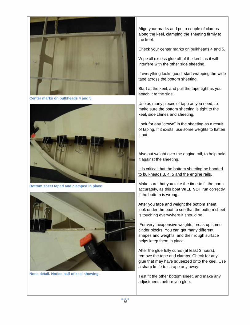
Center marks on bulkheads 4 and 5.
Bottom sheet taped and clamped in place.
Nose detail. Notice half of keel showing.
Align your marks and put a couple of clamps
along the keel, clamping the sheeting firmly to
the keel.
Check your center marks on bulkheads 4 and 5.
Wipe all excess glue off of the keel, as it will
interfere with the other side sheeting.
If everything looks good, start wrapping the wide
tape across the bottom sheeting.
Start at the keel, and pull the tape tight as you
attach it to the side.
Use as many pieces of tape as you need, to
make sure the bottom sheeting is tight to the
keel, side chines and sheeting.
Look for any “crown” in the sheeting as a result
of taping. If it exists, use some weights to flatten
it out.
Also put weight over the engine rail, to help hold
it against the sheeting.
It is critical that the bottom sheeting be bonded
to bulkheads 3, 4, 5 and the engine rails.
Make sure that you take the time to fit the parts
accurately, as this boat WILL NOT run correctly
if the bottom is wrong.
After you tape and weight the bottom sheet,
look under the boat to see that the bottom sheet
is touching everywhere it should be.
For very inexpensive weights, break up some
cinder blocks. You can get many different
shapes and weights, and their rough surface
helps keep them in place.
After the glue fully cures (at least 3 hours),
remove the tape and clamps. Check for any
glue that may have squeezed onto the keel. Use
a sharp knife to scrape any away.
Test fit the other bottom sheet, and make any
adjustments before you glue.
16
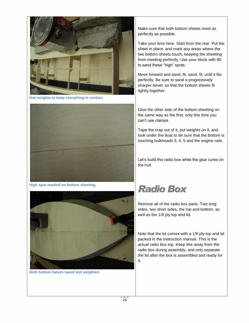
Use weights to keep everything in contact.
High spot marked on bottom sheeting.
Both bottom halves taped and weighted.
Make sure that both bottom sheets meet as
perfectly as possible.
Take your time here. Start from the rear. Put the
sheet in place, and mark any areas where the
two bottom sheets touch, keeping the sheeting
from meeting perfectly. Use your block with 80
to sand these “high” spots.
Move forward and sand, fit, sand, fit, until it fits
perfectly. Be sure to sand a progressively
sharper bevel, so that the bottom sheets fit
tightly together.
Glue the other side of the bottom sheeting on
the same way as the first, only this time you
can’t use clamps.
Tape the crap out of it, put weights on it, and
look under the boat to be sure that the bottom is
touching bulkheads 3, 4, 5 and the engine rails.
Let’s build the radio box while the glue cures on
the hull.
Radio Box
Remove all of the radio box parts: Two long
sides, two short sides, the top and bottom, as
well as the 1/8 ply top and lid.
Note that the kit comes with a 1/8 ply top and lid
packed in the instruction manual. This is the
actual radio box top. Keep this away from the
radio box during assembly, and only separate
the lid after the box is assembled and ready for
it.

17
Radio box sides glued together.
Joining sides.
Bottom glued in place.
The top with lid and the regular top look
identical, but they are not interchangeable.
If you mix them up, you will have a worthless
radio box.
Sand all the parts smooth with 80.
Lay a piece of plastic wrap or waxed paper on
your bench.
Using CA, glue the two small sides to the two
long sides.
The small sides go between the long ones.
Use a square.
Put glue on the edges, and join the two box
halves on the bench.
Lightly sand the bottom of the box.
Note that the bottom is about a half inch too
wide.
This overhang is used to screw the box in place.
Glue on the bottom. Be sure to leave a ¼ inch
overhang on each side of the box.
Lightly sand the top.
Glue the radio box top on.
This is the 1/8 inch Birch top without lid.
Take a break for a few minutes, so that the
radio box glue joints can cure.
Using 80 grit, sand the overhang on the top and
bottom so that it’s flush with the sides.
Sand the top with 180 or 220 grit paper on a
block.
18
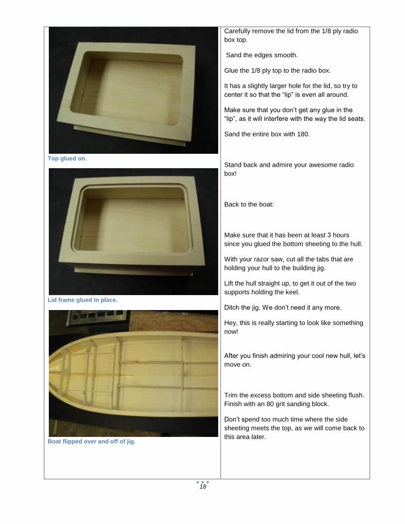
Top glued on.
Lid frame glued in place.
Boat flipped over and off of jig.
Carefully remove the lid from the 1/8 ply radio
box top.
Sand the edges smooth.
Glue the 1/8 ply top to the radio box.
It has a slightly larger hole for the lid, so try to
center it so that the “lip” is even all around.
Make sure that you don’t get any glue in the
“lip”, as it will interfere with the way the lid seats.
Sand the entire box with 180.
Stand back and admire your awesome radio
box!
Back to the boat:
Make sure that it has been at least 3 hours
since you glued the bottom sheeting to the hull.
With your razor saw, cut all the tabs that are
holding your hull to the building jig.
Lift the hull straight up, to get it out of the two
supports holding the keel.
Ditch the jig. We don’t need it any more.
Hey, this is really starting to look like something
now!
After you finish admiring your cool new hull, let’s
move on.
Trim the excess bottom and side sheeting flush.
Finish with an 80 grit sanding block.
Don’t spend too much time where the side
sheeting meets the top, as we will come back to
this area later.
19
Installing spines. Hole goes forward.
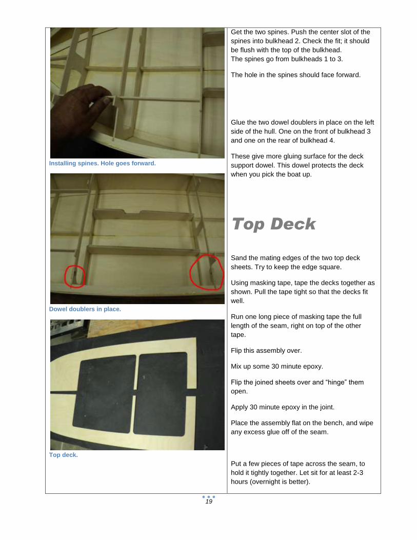
Dowel doublers in place.
Top deck.
Get the two spines. Push the center slot of the
spines into bulkhead 2. Check the fit; it should
be flush with the top of the bulkhead.
The spines go from bulkheads 1 to 3.
The hole in the spines should face forward.
Glue the two dowel doublers in place on the left
side of the hull. One on the front of bulkhead 3
and one on the rear of bulkhead 4.
These give more gluing surface for the deck
support dowel. This dowel protects the deck
when you pick the boat up.
Top Deck
Sand the mating edges of the two top deck
sheets. Try to keep the edge square.
Using masking tape, tape the decks together as
shown. Pull the tape tight so that the decks fit
well.
Run one long piece of masking tape the full
length of the seam, right on top of the other
tape.
Flip this assembly over.
Mix up some 30 minute epoxy.
Flip the joined sheets over and “hinge” them
open.
Apply 30 minute epoxy in the joint.
Place the assembly flat on the bench, and wipe
any excess glue off of the seam.
Put a few pieces of tape across the seam, to
hold it tightly together. Let sit for at least 2-3
hours (overnight is better).
20
“Hinge” glue method.
Top deck taped together until cured.
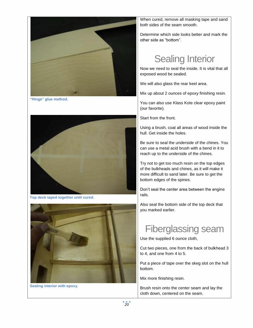
Sealing interior with epoxy.
When cured, remove all masking tape and sand
both sides of the seam smooth.
Determine which side looks better and mark the
other side as “bottom”.
Sealing Interior Now we need to seal the inside. It is vital that all
exposed wood be sealed.
We will also glass the rear keel area.
Mix up about 2 ounces of epoxy finishing resin.
You can also use Klass Kote clear epoxy paint
(our favorite).
Start from the front.
Using a brush, coat all areas of wood inside the
hull. Get inside the holes.
Be sure to seal the underside of the chines. You
can use a metal acid brush with a bend in it to
reach up to the underside of the chines.
Try not to get too much resin on the top edges
of the bulkheads and chines, as it will make it
more difficult to sand later. Be sure to get the
bottom edges of the spines.
Don’t seal the center area between the engine
rails.
Also seal the bottom side of the top deck that
you marked earlier.
Fiberglassing seam Use the supplied 6 ounce cloth,
Cut two pieces, one from the back of bulkhead 3
to 4, and one from 4 to 5.
Put a piece of tape over the skeg slot on the hull
bottom.
Mix more finishing resin.
Brush resin onto the center seam and lay the
cloth down, centered on the seam.

21
Fiberglass on center seam.
Almost invisible with epoxy.
Trim building tabs. We love the flush cut saw for this.
The cloth goes between bulkheads 3 and 4,
then another piece between 4 and the transom.
This cloth reinforces the center seam area and
must not be left out.
Brush in a coat of resin, so that the cloth is
completely wetted.
Continue coating the inside with finishing resin.
If you need to mix more, use a new container
and brush. If you don’t, the old resin will mess
with the new resin, and create a problem. Trust
me…
After you are 100% sure that all exposed wood
inside the hull has been coated, let it sit
overnight.
Now is also a good time to seal the servo
mounts, deck dowel and radio box.
Repeat this process for a second coat. You will
notice that this coat uses far less epoxy, as it
doesn’t have to soak in to the wood like the first
coat.
Sand the underside of the deck with 180 before
laying on the second coat.
After the hull and deck sealer has had a chance
to cure, let’s get the hull ready for the top
sheeting.
Trim the building tabs, and sand the bulkheads
flush with the sides and chines.
Remove the tape from the skeg slot.
Glue the deck support dowel in place.
Use your plane to shave the sides to the same
level as the bulkheads and chines.

22
Deck support dowel glued in.
Aft dowel doubler detail.
Flotation installed. You will have to leave out some to clear the fuel bag. (Zippkits VBox shown).
Do this the same way you did the bottom.
Use 80 grit to finish it up. Be sure not to round
the edges.
Floatation
Now is the time to put floatation in the hull.
DO NOT OMIT THIS STEP! Without floatation
YOU WILL LOSE YOUR BOAT!
You can use white, pink or blue foam, pool
noodles, plastic bottles, almost anything that
floats.
Stay away from spray in foam; it has too many
disadvantages for this use.
If you use blocks of foam, make them as big as
you can.
You can get pool noodles at the dollar store or
Wally World.
Be sure the floatation will not interfere with the
top sheeting.
A boat stand is a good idea at this point.
You can make a boat stand out of PVC pipe or
wood.
If you wish, you can make the mount for your
gas bag now, while the deck is off.
We provided a hole at the right side of BH3 for
this purpose.
Use a spring loaded hook or a strong magnet to
hold the front of your bag.
Let’s get this puppy closed up!

23
Mounting your fuel bag before the deck is on is easier.
Tape all around the top deck and check everywhere.
Tape and weights are the only sure way to bond the deck.
Top Sheeting
Cut about 20 pieces of wide tape for the next
steps.
A shipping tape dispenser works very well for
this.
Mix about 1 ounce of 30 minute epoxy.
Using a stick or acid brush, coat the tops of the
bulkheads, chines and spines with epoxy.
Work quickly.
Start taping the deck down.
Align and tape the center of the deck at
bulkhead 3.
Then align and tape at the nose, then center of
the transom.
Start taping the sides.
Tape tightly.
Check all around to make sure that the deck is
tight against the top of the hull.
Continue adding tape until the entire deck is in
contact all the way around. Check the transom
from behind, and add tape if needed. Check
bulkhead 3 as well. When everything looks
good, add weights to the deck center area.
Allow to cure overnight.
24
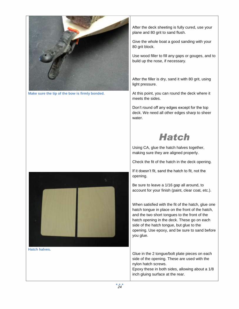
Make sure the tip of the bow is firmly bonded.
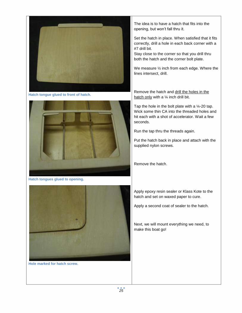
Hatch halves.
After the deck sheeting is fully cured, use your
plane and 80 grit to sand flush.
Give the whole boat a good sanding with your
80 grit block.
Use wood filler to fill any gaps or gouges, and to
build up the nose, if necessary.
After the filler is dry, sand it with 80 grit, using
light pressure.
At this point, you can round the deck where it
meets the sides.
Don’t round off any edges except for the top
deck. We need all other edges sharp to sheer
water.
Hatch Using CA, glue the hatch halves together,
making sure they are aligned properly.
Check the fit of the hatch in the deck opening.
If it doesn’t fit, sand the hatch to fit, not the
opening.
Be sure to leave a 1/16 gap all around, to
account for your finish (paint, clear coat, etc.).
When satisfied with the fit of the hatch, glue one
hatch tongue in place on the front of the hatch,
and the two short tongues to the front of the
hatch opening in the deck. These go on each
side of the hatch tongue, but glue to the
opening. Use epoxy, and be sure to sand before
you glue.
Glue in the 2 tongue/bolt plate pieces on each
side of the opening. These are used with the
nylon hatch screws.
Epoxy these in both sides, allowing about a 1/8
inch gluing surface at the rear.
25
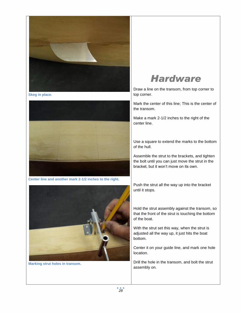
Hatch tongue glued to front of hatch.
Hatch tongues glued to opening.
Hole marked for hatch screw.
The idea is to have a hatch that fits into the
opening, but won’t fall thru it.
Set the hatch in place. When satisfied that it fits
correctly, drill a hole in each back corner with a
#7 drill bit.
Stay close to the corner so that you drill thru
both the hatch and the corner bolt plate.
We measure ½ inch from each edge. Where the
lines intersect, drill.
Remove the hatch and drill the holes in the
hatch only with a ¼ inch drill bit.
Tap the hole in the bolt plate with a ¼-20 tap.
Wick some thin CA into the threaded holes and
hit each with a shot of accelerator. Wait a few
seconds.
Run the tap thru the threads again.
Put the hatch back in place and attach with the
supplied nylon screws.
Remove the hatch.
Apply epoxy resin sealer or Klass Kote to the
hatch and set on waxed paper to cure.
Apply a second coat of sealer to the hatch.
Next, we will mount everything we need, to
make this boat go!

26
Hatch screwed in place.
Servo mount parts.
Assembled servo mount.
Radio:
Find the 4 pieces of ¼ inch ply, and the 2 servo
mount bases.
These are the servo mounts.
The two larger ¼ inch ply blocks go with the
large base and vice versa.
Using CA, glue one of the ¼ ply pieces flush
with the end of the base.
Use a piece of waxed paper or cling wrap on the
bench, so the part doesn’t become a permanent
part of your bench…
Set your servo on its side in the servo mount.
Check the position of the other ¼ ply piece.
Most servos will have this flush with the end of
the base. Adjust yours as needed.
You may need to cut one of the ¼ ply pieces to
clear your servo wire. If so, take off only enough
to clear.
Remove the servo and glue the other ply piece
in place with CA.
Once cured, put the servo back in place and
check that the servo is a tiny bit taller than the
height of the ¼ ply blocks. If not, sand the tops
of the blocks until they are about 1/32 inch lower
than the servo.
Put the servo strap in place and drill 1/16 pilot
holes in the ¼ ply. Be careful to drill straight.
Repeat for the other servo.

27
Servo mount ready to go.
Seal the radio box, inside and out.
Skeg slot relieved for skeg.
Grab the radio box, and coat the inside and
outside with finishing resin or Klass Kote.
Be careful not to get any buildup in the lip,
where the lid seats. It will make it impossible for
the lid to seal properly. To get inside the upper
part, bend an acid brush about 120 degrees,
and it works very well.
You can seal the inside, top and all four sides of
the outside in one session.
Also seal the servo mounts and straps.
Allow to cure overnight.
When cured, seal with a second coat.
Center Skeg We have provided a slot for the skeg in the
bottom sheeting.
Check to see that the skeg fits properly. If not,
find out why and correct it. You will have to
relieve one side of the skeg slot, as the skeg
has a fillet on one side because it is structural
aluminum.
If all is well, pull the skeg out, and set aside. It
will be epoxied in place just before painting.
28
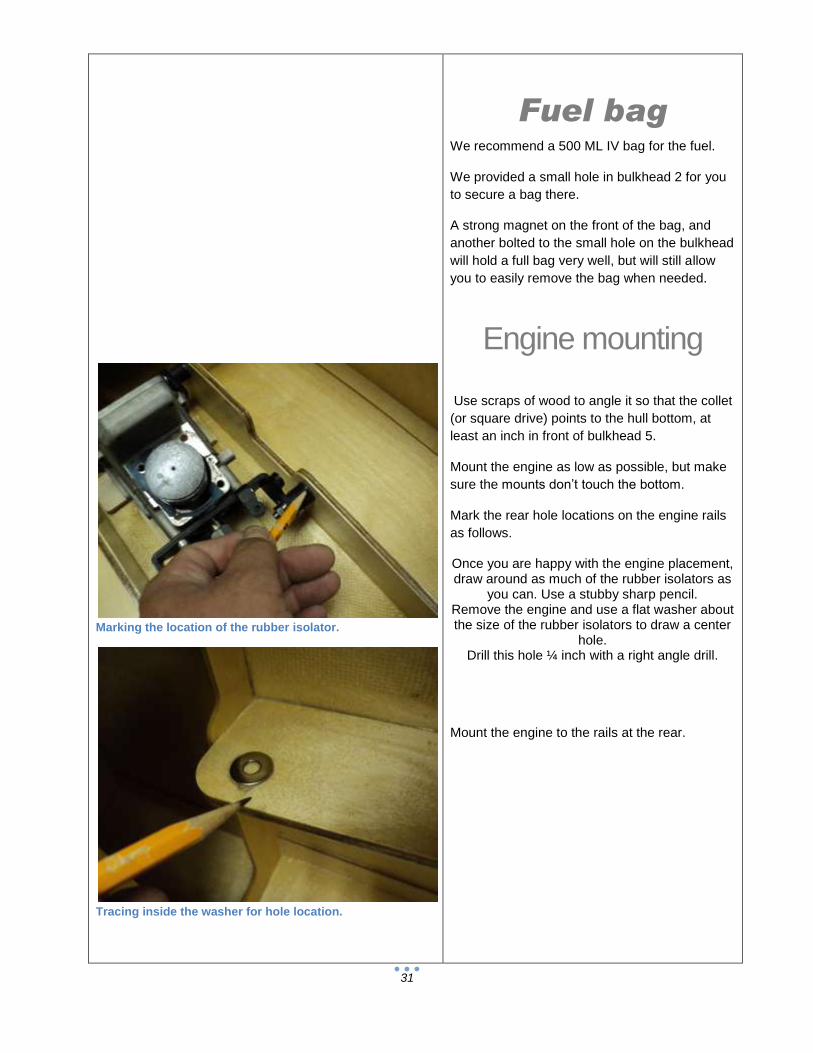
Skeg in place.
Center line and another mark 2-1/2 inches to the right.
Marking strut holes in transom.
Hardware Draw a line on the transom, from top corner to
top corner.
Mark the center of this line; This is the center of
the transom.
Make a mark 2-1/2 inches to the right of the
center line.
Use a square to extend the marks to the bottom
of the hull.
Assemble the strut to the brackets, and tighten
the bolt until you can just move the strut in the
bracket, but it won’t move on its own.
Push the strut all the way up into the bracket
until it stops.
Hold the strut assembly against the transom, so
that the front of the strut is touching the bottom
of the boat.
With the strut set this way, when the strut is
adjusted all the way up, it just hits the boat
bottom.
Center it on your guide line, and mark one hole
location.
Drill the hole in the transom, and bolt the strut
assembly on.

29
Strut mounted to transom.
Rudder and strut mounted.
Measuring 3-3/4 from center for inside of trim tab.
Check to see that the strut is aligned with your
reference line, and mark the other three holes.
Drill the transom and install the three bolts and
nuts.
Assemble the rudder to the brackets.
Mount it the same way you did the strut, aligning
the rudder blade to your reference line, 2-1/2
inches to the right of center.
The top of the rudder bracket and the top of the
strut bracket should be the same.
The rudder should extend at least 2-1/2 inches
below the bottom of the hull.
Trim Tabs Mount your trim tabs to the transom so that they
are flush or just a hair up from the bottom. No
more than 1/16 inch above the bottom
Also mount them so that they are 3-3/4 inches
from the center of the hull.
Turn fin The turn fin should be mounted on the extreme right side of the transom, above the trim tabs. Make sure the fin is 90 degrees to the bottom. It will be canted outward with the hull level.
The turn fin should extend about 2-1/2 inches below the bottom of the hull.

30
All transom hardware mounted.
Drive dog and prop in place.
Shaft filed for drive dog set screw.
Turn fin 90 degrees to bottom. Bottom angle exaggerated for clarity.
Flex cable prep
Get the flex cable, drive dog, prop and prop nut.
Put the drive dog on the stub shaft, then the
prop.
Engage the drive dog into the prop, and slide
this assembly back until the prop covers about
half of the threads on the stub shaft. Tighten the
drive dog set screw.
Mark the stub shaft at the front of the drive dog.
Remove the dog and prop.
Measure 3/16 inch back from your line, and file
a flat spot, about 1/8 inch wide and 1/16inch
deep.
This is for the set screw. File off any burrs, and
put the drive dog back on, tightening the set
screw into the flat.
Center of Gravity
Mount engine as far forward as possible!
The CG should be 34 to 36 percent forward of
the transom.
This would be 13-1/2 to 16 inches.
31
Marking the location of the rubber isolator.
Tracing inside the washer for hole location.
Fuel bag We recommend a 500 ML IV bag for the fuel.
We provided a small hole in bulkhead 2 for you
to secure a bag there.
A strong magnet on the front of the bag, and
another bolted to the small hole on the bulkhead
will hold a full bag very well, but will still allow
you to easily remove the bag when needed.
Engine mounting
Use scraps of wood to angle it so that the collet
(or square drive) points to the hull bottom, at
least an inch in front of bulkhead 5.
Mount the engine as low as possible, but make
sure the mounts don’t touch the bottom.
Mark the rear hole locations on the engine rails
as follows.
Once you are happy with the engine placement, draw around as much of the rubber isolators as
you can. Use a stubby sharp pencil. Remove the engine and use a flat washer about the size of the rubber isolators to draw a center
hole. Drill this hole ¼ inch with a right angle drill.
Mount the engine to the rails at the rear.

32
Engine mounted.
Drill bit shows position of shaft.
Stuffing tube in place.
Put a ¼ inch drill bit in the collet. Block up the
front of the engine, and mark the rails as before.
Make sure the drill bit is pointing to the center of
the boat, and at least an inch in front of
bulkhead 5. Also use it to determine the exact
location of the hole for the stuffing tube in the
hull bottom.
Remove the engine and drill the front mounting
holes.
Remove all the hardware.
Bolt the engine back in, using all 4 mounts.
Mark the location of the hole for the stuffing
tube.
Cover the engine to keep dust out of it.
Stuffing tube
Drill a 3/8 hole, about ½ inch behind your mark
for the stuffing tube. Use a round file to elongate
this hole to match the angle of the engine.
To get the exact angle, you can wrap masking
tape on the drill, and slide the 11/32 stuffing
tube over that, to get it centered.
Note that this tube is not the 5/16 shaft tube,
this is the stuffing tube that the shaft tube fits
into. Got it?
We like to use a stuffing tube with any boat with
an exposed shaft tube. If you hit something and
damage the shaft tube, it is easily replaced.
When the hole is opened up properly, the 11/32
stuffing tube will slide onto the drill bit and tape
without interference.
33
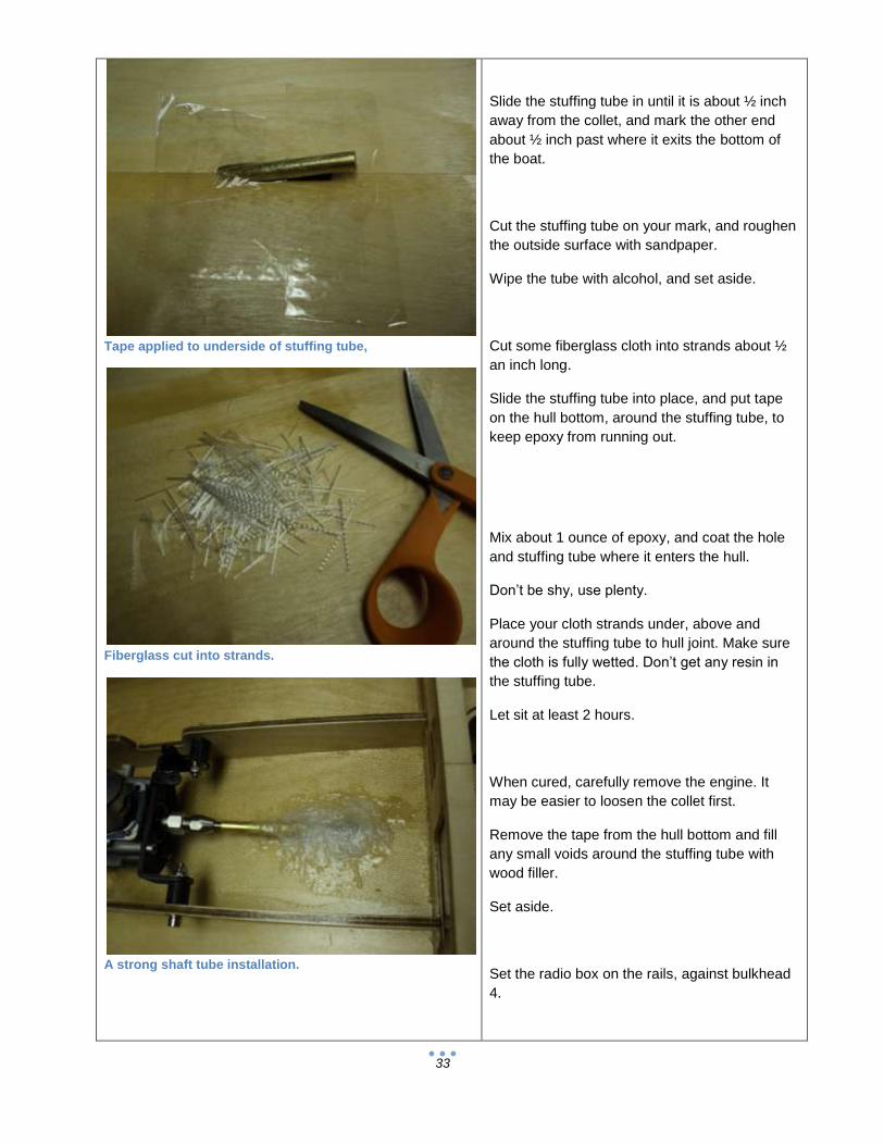
Tape applied to underside of stuffing tube,
Fiberglass cut into strands.
A strong shaft tube installation.
Slide the stuffing tube in until it is about ½ inch
away from the collet, and mark the other end
about ½ inch past where it exits the bottom of
the boat.
Cut the stuffing tube on your mark, and roughen
the outside surface with sandpaper.
Wipe the tube with alcohol, and set aside.
Cut some fiberglass cloth into strands about ½
an inch long.
Slide the stuffing tube into place, and put tape
on the hull bottom, around the stuffing tube, to
keep epoxy from running out.
Mix about 1 ounce of epoxy, and coat the hole
and stuffing tube where it enters the hull.
Don’t be shy, use plenty.
Place your cloth strands under, above and
around the stuffing tube to hull joint. Make sure
the cloth is fully wetted. Don’t get any resin in
the stuffing tube.
Let sit at least 2 hours.
When cured, carefully remove the engine. It
may be easier to loosen the collet first.
Remove the tape from the hull bottom and fill
any small voids around the stuffing tube with
wood filler.
Set aside.
Set the radio box on the rails, against bulkhead
4.
34
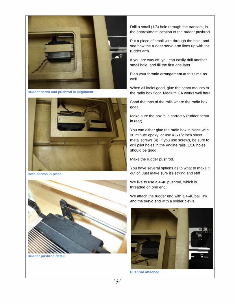
Rudder servo and pushrod in alignment.
Both servos in place.
Rudder pushrod detail.
Drill a small (1/8) hole through the transom, in
the approximate location of the rudder pushrod.
Put a piece of small wire through the hole, and
see how the rudder servo arm lines up with the
rudder arm.
If you are way off, you can easily drill another
small hole, and fill the first one later.
Plan your throttle arrangement at this time as
well.
When all looks good, glue the servo mounts to
the radio box floor. Medium CA works well here.
Sand the tops of the rails where the radio box
goes.
Make sure the box is in correctly (rudder servo
in rear).
You can either glue the radio box in place with
30 minute epoxy, or use #2x1/2 inch sheet
metal screws (4). If you use screws, be sure to
drill pilot holes in the engine rails. 1/16 holes
should be good.
Make the rudder pushrod.
You have several options as to what to make it
out of. Just make sure it’s strong and stiff
We like to use a 4-40 pushrod, which is
threaded on one end.
We attach the rudder end with a 4-40 ball link,
and the servo end with a solder clevis.
Pushrod attached.
35
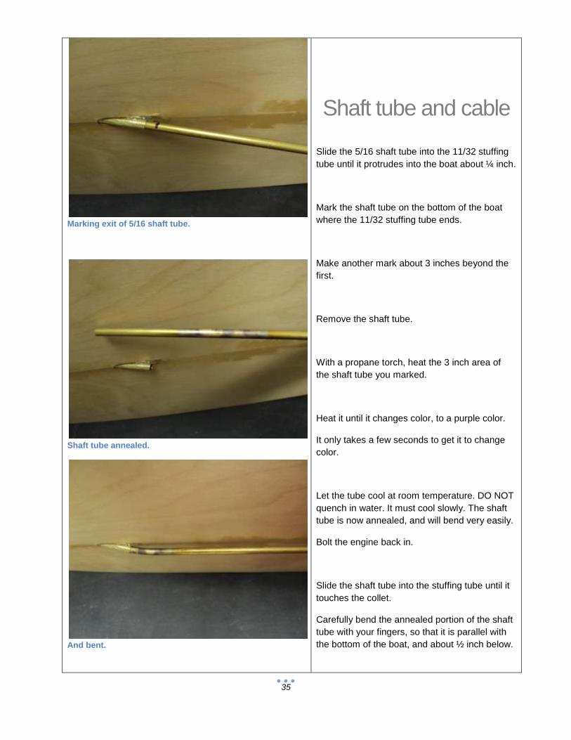
Marking exit of 5/16 shaft tube.
Shaft tube annealed.
And bent.
Shaft tube and cable
Slide the 5/16 shaft tube into the 11/32 stuffing
tube until it protrudes into the boat about ¼ inch.
Mark the shaft tube on the bottom of the boat
where the 11/32 stuffing tube ends.
Make another mark about 3 inches beyond the
first.
Remove the shaft tube.
With a propane torch, heat the 3 inch area of
the shaft tube you marked.
Heat it until it changes color, to a purple color.
It only takes a few seconds to get it to change
color.
Let the tube cool at room temperature. DO NOT
quench in water. It must cool slowly. The shaft
tube is now annealed, and will bend very easily.
Bolt the engine back in.
Slide the shaft tube into the stuffing tube until it
touches the collet.
Carefully bend the annealed portion of the shaft
tube with your fingers, so that it is parallel with
the bottom of the boat, and about ½ inch below.

36
Marking depth of shaft tube inside strut.
Shaft tube installed.
Rear portion of shaft tube annealed.
Put the long end of the brass tube into the strut.
Push it all the way in and make a mark on the
brass tube at the front of the strut.
Remove the strut and measure how far it went
into the strut. Write this down.
Bolt the strut on with 2 bolts. Make sure you can
adjust the strut freely.
Set the strut so that its centerline is about ½
inch below the bottom of the boat, and parallel.
Adjust the shaft tube so that it is aligned with the
strut. You can turn the tube slightly in the
stuffing tube, so that it’s next to the strut.
Make a mark where the front of the strut is, and
remove the tube.
Make another mark back from your first, using
the measurement you wrote down earlier.
Cut the shaft tube here, and file the end smooth.
Remove the strut, slide the shaft tube into the
stuffing tube and slide the strut onto the end of
the shaft tube. It should easily bolt to the
transom.
If not, find out why and correct it.
When satisfied with the shaft tube, mark the
front and cut it to the same (distance from the
collet) as the stuffing tube. File any burrs.
You may also want to anneal the rear of the
tube, slightly forward of the strut nose.
This makes strut adjustments easier as you can
slightly bent the shaft tube here when you make
strut angle changes.
Reinstall the strut and shaft tube (again?).
Loosen the collet and slide your assembled flex
shaft in until it bottoms out in the collet. Do this
several times, and make sure it goes in all the
way (at least about ¾ of an inch).

37
Measuring flex shaft.
Leave a gap at the rear for flex shaft “wind up”.
Exhaust and plumbing detail.
Tighten the collet slightly with two wrenches.
Measure the distance from the back of the strut
to the front of the drive dog. Subtract 1/4 inch
from your measurement.
We want the shaft ¼ inch too long.
Remove the cable assembly and cut the cable
by the amount you just determined.
To cut the cable, use a motor tool with a cut off
disk, and file or grind the end smooth.
Put the cable back in and there should be a 1/4
inch gap between the strut and drive dog.
You must have this ¼ gap when running, as the
cable will “wrap up” and get shorter in use.
Exhaust Plan the exhaust carefully. It usually must exit
the transom to be legal.
We use a 3 inch offset 90 degree header and
tuned pipe.
Be sure that your pipe is mounted firmly near
the outlet.
Never pull a pipe to one side to mount it. Even if
you only put a little side pressure on the pipe
when mounting, it can leak water into the pipe
and kill performance.
38
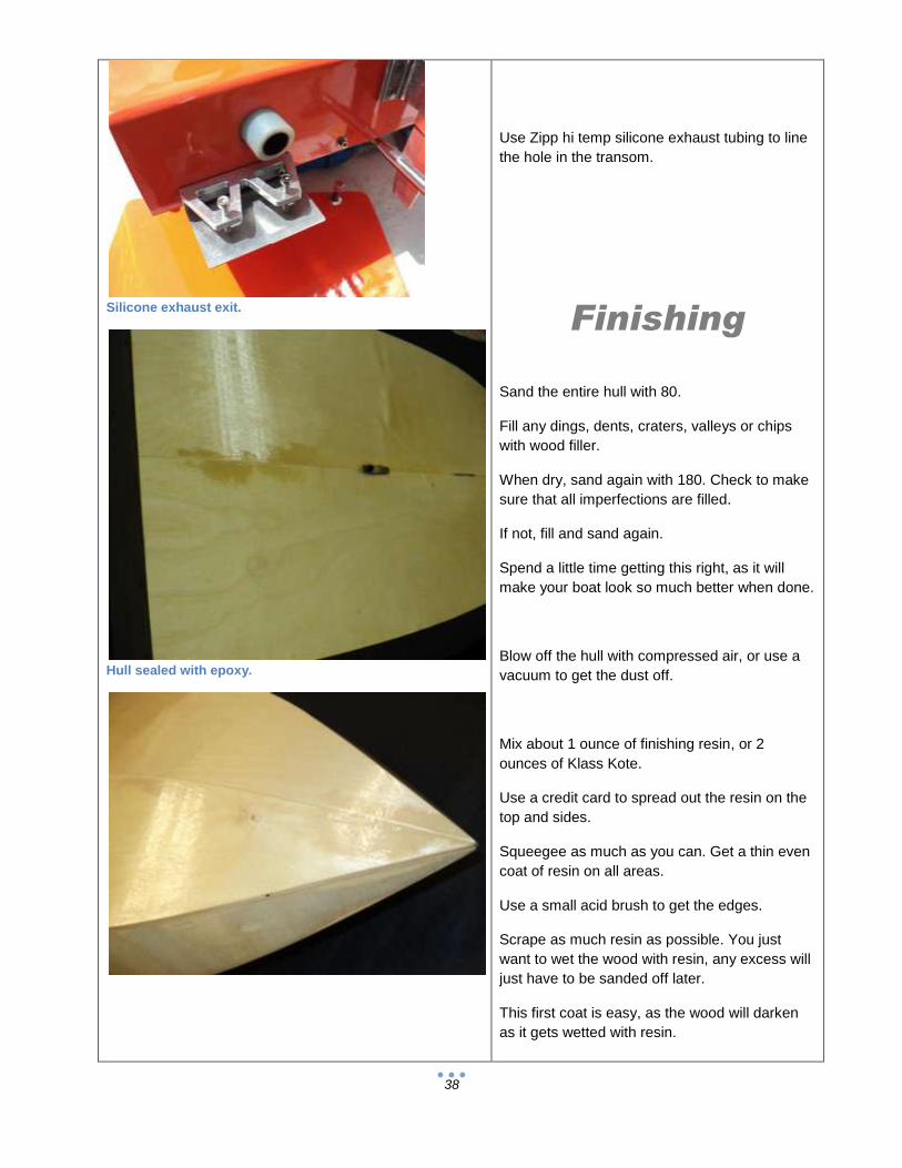
Silicone exhaust exit.
Hull sealed with epoxy.
Use Zipp hi temp silicone exhaust tubing to line
the hole in the transom.
Finishing
Sand the entire hull with 80.
Fill any dings, dents, craters, valleys or chips
with wood filler.
When dry, sand again with 180. Check to make
sure that all imperfections are filled.
If not, fill and sand again.
Spend a little time getting this right, as it will
make your boat look so much better when done.
Blow off the hull with compressed air, or use a
vacuum to get the dust off.
Mix about 1 ounce of finishing resin, or 2
ounces of Klass Kote.
Use a credit card to spread out the resin on the
top and sides.
Squeegee as much as you can. Get a thin even
coat of resin on all areas.
Use a small acid brush to get the edges.
Scrape as much resin as possible. You just
want to wet the wood with resin, any excess will
just have to be sanded off later.
This first coat is easy, as the wood will darken
as it gets wetted with resin.
39
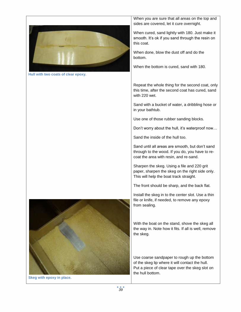
Hull with two coats of clear epoxy.
Skeg with epoxy in place.
When you are sure that all areas on the top and
sides are covered, let it cure overnight.
When cured, sand lightly with 180. Just make it
smooth. It’s ok if you sand through the resin on
this coat.
When done, blow the dust off and do the
bottom.
When the bottom is cured, sand with 180.
Repeat the whole thing for the second coat, only
this time, after the second coat has cured, sand
with 220 wet.
Sand with a bucket of water, a dribbling hose or
in your bathtub.
Use one of those rubber sanding blocks.
Don’t worry about the hull, it’s waterproof now…
Sand the inside of the hull too.
Sand until all areas are smooth, but don’t sand
through to the wood. If you do, you have to re-
coat the area with resin, and re-sand.
Sharpen the skeg. Using a file and 220 grit
paper, sharpen the skeg on the right side only.
This will help the boat track straight.
The front should be sharp, and the back flat.
Install the skeg in to the center slot. Use a thin
file or knife, if needed, to remove any epoxy
from sealing.
With the boat on the stand, shove the skeg all
the way in. Note how it fits. If all is well, remove
the skeg.
Use coarse sandpaper to rough up the bottom
of the skeg lip where it will contact the hull.
Put a piece of clear tape over the skeg slot on
the hull bottom.

40
Bottom view of skeg mounted.
Mix up some 30 minute epoxy, about ½ ounce.
Coat the edges of the skeg slot and the bottom
of the skeg lip with epoxy.
Push the skeg into the slot, piercing the tape as
you do so. Put epoxy all around the edges of
the skeg, inside the boat. Don’t coat the top of
the lip, as you may need to remove the skeg at
some point.
Before the epoxy cures, sight from behind the
boat, and see if the skeg is straight. If it is tilted
to one side, put a piece of waxed paper over the
skeg and epoxy, and use a weight to hold the
skeg straight.
You can also prop something against the skeg
under the boat.
Let this sit for at least 3 hours.
If you ever need to remove the skeg, use a heat
gun or propane torch to warm the aluminum,
then simply tap it out from the bottom with a
block of wood. Heat softens the epoxy.
Once the skeg is fully cured, wipe the hull down
with alcohol. Use a tack cloth lightly to remove
any dust.
Tape over the skeg with masking tape, so it
doesn’t get paint on it.
Also mask the openings in the hull from primer
overspray.
Spray a light coat of primer. Let this flash for a
few minutes, and spray a heavy coat on.
Let sit overnight.
When the primer is dry, use icing or body filler to
fill any nicks or surface imperfections.
When dry, wet sand with 400 on a rubber block.
Install water lines.

41
If you are happy with the surface, spray on another
medium coat of primer.
When dry, wet sand with 600 or 800.
Watch out for the sharp skeg…
Use compressed air or a vacuum to remove the dust on
the inside and outside of the hull.
Wipe down the entire boat with alcohol.
Use a tack cloth to lightly wipe all surfaces.
Spray your color coats.
When cured, wet sand with 800+ and clear coat
the entire hull.
Make sure the clear is completely cured before final
assembly.
To apply your decals, wipe the area with alcohol and
allow to dry before applying decals.
Final assembly
Before you bolt anything to the hull, give it a good coat of
paste wax.
Put the boat on your stand. This is where it will live, when
it’s not in the water.
Install the engine.
Install the shaft tube.
Install the strut, pushing the end of the shaft tube all the
way in. Leave the strut loose in the brackets.
Install the rudder assembly
Install the sharpened and balanced prop and prop nut on
the flex shaft.
Install the fuel bag and fuel lines.
Install the bulkhead fittings and water outlets.
Install exhaust.
Push the threaded end of the rudder and throttle
pushrods through the big end of the pushrod
seals.
Attach both ends of the pushrods, making sure
the seals are on the outside of the radio box.
Install your antenna.
Setup Adjust the strut so that its center is exactly ½
inch below the bottom of the hull and about 1
degree negative (the prop end of the strut is
slight lower).
Grease the flex cable.
Slide the cable through the strut, into the engine
collet.
Leave a ¼ inch gap between the drive dog and
strut.
Tighten the collet.
Wrap your receiver, failsafe and battery pack in
foam rubber.
Mount the switch.
Turn the transmitter on first, then the receiver.
Make sure the trims are centered.
Put the rudder servo arm on. It should be
parallel with the servo and 90 degrees to the
pushrod. Use the sub trim function, if your radio
has it. If not, get it as close as you can.
If you are going to run the boat on the stand,
take the prop off, but leave the shaft connected
to the engine. This will help to “break in” the
strut bushings.
42
Attach the rudder to the pushrod. Is the rudder straight? If
not, adjust the clevis or ball link until it is.
Be sure to put the screw in the servo arm…
Adjust the throttle so that the carb is wide open when you
pull the trigger all the way back, and closed when you
push the trigger forward.
When the engine is running, you can use the throttle trim
to set the idle speed.
Take the time to get this right. It’s no fun running your
boat onto the shore because the engine won’t shut off…
Make sure all your water lines are firmly attached. Use
those teeny little tie wraps at each fitting.
Running
If you are using a new engine, you should run it on the
stand before going to the pond.
This will do several things; It will allow the engine to
loosen up a little, making starting a simple matter, as well
as get YOU familiar with its starting and running
characteristics.
When new, the engines are very tight, and starting is
difficult at best.
You will need to supply cooling water to the engine and
exhaust while running on the stand.
You can make a nice little unit with a garden hose valve
and nozzle. Epoxy a piece of 5/32 brass tubing to the
nozzle and you are ready.
Adjust the water flow so that there is a stream of water
about 2 inches coming from the outlets.
Now is the time to check all water connections for leaks.
Under no circumstances should you ever run a marine
engine for an extended time without cooling water.
At the pond
Make sure your transmitter and receiver
batteries are fresh, or fully charged.
Do a range check with your transmitter antenna
down or select low power, and note the
distance. You should do a range check every
day that you run. Should a problem arise, you
can fix it before you damage anything.
Tape the lid on the radio box with radio box
tape, or use Scotch Plastic Tape. Regular tape
leaves a residue.
Make sure that your prop is sharp and
balanced.
Make sure the trim tabs are flush, and not up or
down. Use a small straightedge to check.
Make sure all screws and nuts are tight.
Fill the fuel bag; turn on your transmitter, then
receiver.
Wiggle the rudder so you know it works, and
then start the engine.
Don’t rev the engine much, as there is no load
on the prop until it’s in the water.
To launch, have a helper drop the boat in level.
You can give it a little gas as it gets to the water,
but not too much. Most people don’t like getting
sprayed with water…
Let the engine warm up for 30 seconds or so
before giving it full throttle.
Drive past yourself, and make sure you have a
stream of cooling water.
43
If you don’t see any cooling water, bring it in
pronto! Fix this before you cook things…
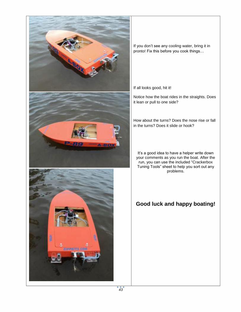
If all looks good, hit it!
Notice how the boat rides in the straights. Does
it lean or pull to one side?
How about the turns? Does the nose rise or fall
in the turns? Does it slide or hook?
It’s a good idea to have a helper write down your comments as you run the boat. After the
run, you can use the included “Crackerbox Tuning Tools” sheet to help you sort out any
problems.
Good luck and happy boating!

44
Cracker Box tuning tools
Strut: Depth- Lower to loosen the boat, higher to wet the boat. Imagine that the prop wants to always ride at the same depth in the water. If you lower the prop, you are lifting the boat out of the water. The reverse is true for raising the strut; it lowers the boat in the water. Strut: Angle- Negative to push the bow down, positive to push the stern down. This is a course ride angle adjustment. Small changes in the strut angle make large changes in ride attitude. Trim Tabs: Inner- Use these for fine adjustment of the ride attitude, as well as to control torque and prop walk. Outer- use these for fine adjustments to turns. Rudder: Trim- Use this to make the boat go straight. The rudder should be parallel to the hull centerline. Anything less will rob speed. If you have to trim left, it’s probably prop walk. Rudder: angle- Use this to control the nose in turns. Kicking the bottom of the rudder forward will cause the nose to rise in the turns. Kicking the bottom back will cause the nose to drop in the turns. It only takes a little; 5 degrees either way would be too much for most hulls. Turn fin: This is mounted to the right side of the transom, and 90 degrees to the bottom of the hull. Make sure that there is never any fin area forward of the pivot bolt (kick it back slightly). CG: This is the longitudinal (fore and aft) balance of the hull. Monos are usually 30-35 percent of the hull length, from the transom. This is the pivot point for turning. A forward CG keeps the hull wetter, preventing blowovers. Limits absolute top speed due to drag. An aft CG keeps the hull out of the water, and usually blows over with very high speed. That’s why they call it a “balance” point… Prop: The prop is very important to speed, as well as overall handling of the boat. You can (and should) experiment with many props, lifting and non lifting, to get the best speed and handling from your boat. Always sharpen and balance your props! A sharp prop helps reduce “prop walk”, and a balanced one usually stays together! Skeg: The skeg should be sharpened on the right side only. This makes the boat
pull slightly to the left, reducing or eliminating the need for right rudder trim.
45
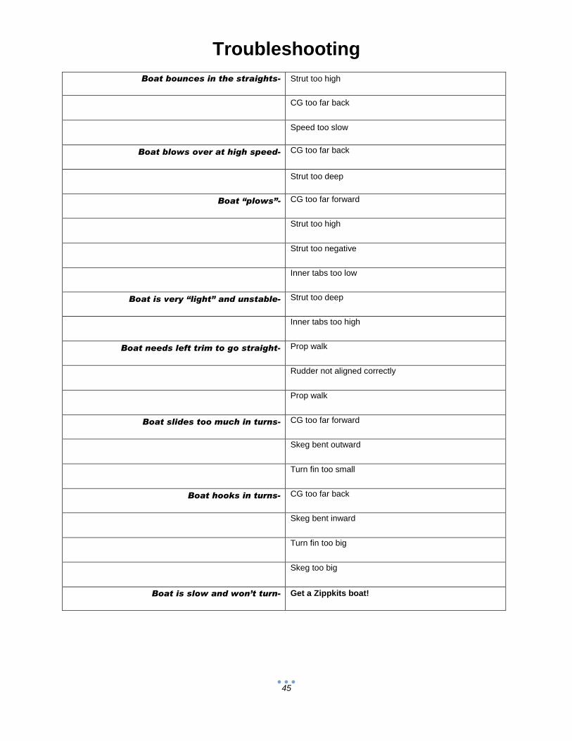
Troubleshooting
Boat bounces in the straights- Strut too high
CG too far back
Speed too slow
Boat blows over at high speed- CG too far back
Strut too deep
Boat “plows”- CG too far forward
Strut too high
Strut too negative
Inner tabs too low
Boat is very “light” and unstable- Strut too deep
Inner tabs too high
Boat needs left trim to go straight- Prop walk
Rudder not aligned correctly
Prop walk
Boat slides too much in turns- CG too far forward
Skeg bent outward
Turn fin too small
Boat hooks in turns- CG too far back
Skeg bent inward
Turn fin too big
Skeg too big
Boat is slow and won’t turn- Get a Zippkits boat!
46
ABox Initial setup:
Set strut 1 degree negative with bottom, and the prop centerline at ½ inch below the bottom.
The strut will almost touch the bottom at this setting.
Use the Zipp 670 prop (or a Prather 270).
Trim tabs should be about 1/16 inch higher than the bottom of the hull bottom.
Set the tabs parallel to the bottom with a ruler or straight edge (they will be 1/16 from the
ruler).
Run the boat, and adjust the strut so that the boat is fast, and runs slightly nose up. The boat
should ride so that you can just see the bottom skeg in the straights.
If the boat starts to fly, move the strut up 1/16 at a time until it doesn’t.
Adjust the strut depth and angle to get the boat running well. Don’t touch the tabs until the
strut is set…
When you have the hull running nice in the straights, it’s time to get the turns working.
When you adjust the trim tabs, remember that they are very sensitive. ¼ turn will be noticeable.
Look at how the boat turns. Does it hop and roll in the turns? If so, drop the right outer tab ½
turn, and try again.
What you want to see is the entire right side of the hull in the water when it turns. This is very
evident if you watch where the water breaks from the hull as you go into a turn. It should
quickly move forward as you deflect the rudder.
Reduce the rudder throw until the boat will just turn on the buoys, and then increase it a little
bit.
You will never need any more than this, and too much can flip the boat easily.
Once you get the turns working, use the two center tabs (together) to adjust the hull’s
ride from day to day, as conditions require. If in doubt, make it wet. The water is NEVER
calm when there are 5 or 6 other boats out there.
If you use a stinger (surface) drive, you will probably use a larger prop, but the rest of
the adjustments should be done the same way. Take the time to get everything right
and you will be rewarded with an incredible running Crackerbox!

47
Driving Your ABox
The ABox is one of the easiest driving Crackerboxes available.
It is however, still a Crackerbox.
They love to go fast, but hate to turn. They are known to be unpredictable at times…
Ours turns very well, and is predictable if you follow these tips:
1) Setup your boat so that it is not on the ragged edge.
This may look impressive, but you will never finish a race.
Most racing organizations have this silly rule that you must finish before you can win.
Trim for a slightly “wet” ride.
2) Ease into the turns.
When you turn this boat, it quickly slows down on its own.
If you are going very fast and turn quickly, the boat will not have slowed enough to
make a sharp turn and will do spectacular barrel rolls.
To turn correctly, give a tiny bit of right rudder to slow the boat just before you make a
full turn.
This will slow the boat slightly, and allow you to feed in more rudder.
It only takes a little bit of rudder to do this, and you will quickly learn how to manage
the running attitude this way.
If the conditions get a little rough and your boat is starting to fly, you can “blip” right
rudder to calm it down in the straights.
3) Practice!
This is really the only way to get good at anything.
Try to run in any condition (windy, hot, cold, crowded water) so that you know exactly
how the boat will react in these situations.

48
Additional information
Jim’s RC Boat Dock Website
www.jrcbd.com
Excellent forum for information on gas R/C boats
Bonzi Sports Website
www.bonzisports.com Source for Zenoah engines and accessories
IMPBA Website
www.impba.net
National Model Boating Organization
NAMBA Website
www.namba.com
National Model Boating Organization