crack tip position determination using infrared...
TRANSCRIPT
Crack Tip Position Determination Using Infrared Thermography and Digital Image Correlation
by P. Čanžar**, Z. Tonković*, I. Boras* and S. Švaić*
*Faculty of Mechanical Engineering and Naval Architecture, Univ. of Zagreb, I. Lučića 5, Zagreb, Croatia, {zdenko.tonkovic, ivanka.boras, martin.surjak, janos.kodvanj, srecko,svaic}@fsb.hr **Končar – Electrical Engineering Institute, Fallerovo šetalište 22, Zagreb, Croatia, [email protected]
Abstract
This paper presents an experimental and numerical study of the crack initiation and propagation in the nodular cast iron grade EN-GJS-400-18-LT. Therein, non-contact Digital Image Correlation is used to study the development of the tensile damage along the crack path and to identify the crack tip position. Based on the experimental results, a new three-dimensional constitutive model is proposed to simulate the low-cycle fatigue behaviour of considered material. Within the framework of numerical investigations the cyclic plasticity model together with the damage initiation and evolution criteria are applied to study the fatigue damage in the compact tension specimen near the notch and the crack tip. The computational procedure accuracy is verified by comparing the computed results with the real experimental data. After successful application of the digital image correlation technique to identify the crack tip position, the next step is to investigate the development of the dissipated energy along the crack path using the infrared thermography.
1. Introduction
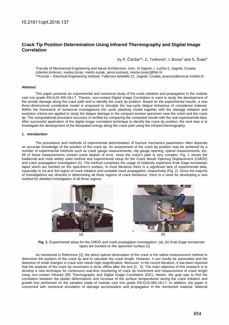
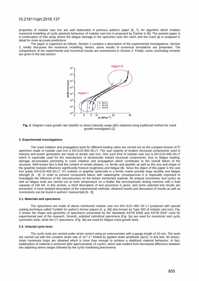
The procedures and methods of experimental determination of fracture mechanics parameters often depends on accurate knowledge of the position of the crack tip. An assessment of the crack tip position may be achieved by a number of experimental methods such as crack gauge measurements, clip gauge opening, optical measurements, etc. All of these measurements contain some degree of error, since the crack's path is very complex. Fig. 1 shows the traditional and most widely used method and experimental setup for the Crack Mouth Opening Displacement (CMOD) and crack propagation investigation [1]. The method comprises the usage of relatively expensive Krak Gage konstantan tapes which are bonded on the specimen’s surface. In most literature there is a significant lack of experimental data, especially in 1st and 3rd region of crack initiation and unstable crack propagation, respectively (Fig. 2). Since the majority of investigations are directed in determining all three regions of crack behaviour, there is a need for developing a new method for detailed investigation of all three regions.
(a) (b)
Fig. 1. Experimental setup for the CMOD and crack propagation investigation: (a), (b) Krak-Gage konstantan
tapes are bonded on the specimen surface [1]
As mentioned in Reference [2], the direct optical observation of the crack is the safest measurement method to determine the position of the crack tip and to calculate the crack length. However, it can hardly be automated and the detection of small changes in crack size needs high magnification. Moreover, in the recent literature, it has been reported that the analysis of the crack tip movement is done offline after the test [3 - 5]. The main objective of this research is to develop a new technique for continuous real-time monitoring of crack tip movement and measurement of crack length using non-contact Infrared (IR) Thermography and Digital Image Correlation (DIC). Herein, the goal was to find the correlation between the plastic deformations and increase of the surface temperatures during the crack initiation and growth test performed on the samples made of nodular cast iron grade EN-GJS-400-18-LT. In addition, the paper is concerned with numerical simulation of damage accumulation and propagation in the mentioned material. Material
10.21611/qirt.2016.137
854
properties of nodular cast iron are well elaborated in previous authors' paper [6, 7]. An algorithm which enables numerical modelling of cyclic plasticity behaviour of nodular cast iron is proposed by Čanžar in [8]. The present paper is a continuation of that study where the fatigue damage in the specimen near the notch and the crack tip is analysed in detail for more accurate predictions.
The paper is organized as follows. Section 2 contains a description of the experimental investigations. Section 3, briefly discusses the numerical modelling. Herein, some results of numerical simulations are presented. The comparisons of the experimental and numerical results are summarized in Section 4. Finally, some concluding remarks are given in the last section.
Fig. 2. Diagram crack growth rate (da/dN) vs stress intensity range (ΔK) obtained using traditional method for crack growth investigation [1]
2. Experimental investigations
The crack initiation and propagation tests for different loading ratios are carried out on the compact tension (CT) specimen made of nodular cast iron is EN-GJS-400-18-LT. The vast majority of modern structural components used in industry and power generation are made of ductile cast iron. One such kind of nodular cast iron is EN-GJS-400-18-LT which is especially used for the manufacture of dynamically loaded structural components. Due to fatigue loading, damage accumulates preceding in crack initiation and propagation which contributes to the overall failure of the structure. Well known fact is that the content of certain phases, i.e. ferritic and pearlitic as well as the size and shape of the graphite nodules influences significantly fracture toughness and fatigue life. Since the object of this paper is the cast iron grade EN-GJS-400-18-LT, it’s nodules or graphite spheroids in a ferritic matrix provide large ductility and fatigue strength [6 - 8]. In order to prevent component failure with catastrophic consequences it is especially important to investigate the influence of the microstructure on the before mentioned material. All uniaxial (monotonic and cyclic) as well as fatigue tests are carried out at room temperature on a Walter Bai servohydraulic testing machine with a load capacity of ±50 kN. In this section, a short description of test procedure is given, and some selected test results are presented. A more detailed description of the experimental methods, obtained results and discussion of results as well as conclusions can be found in authors' manuscripts [6 - 8]. 2.1. Materials and specimens
The specimens are made of above mentioned nodular cast iron EN−GJS−400−18−LT produced with special casting technique called Tundish (in author’s former papers (e. g. [6]) also known as Type 300 of nodular cast iron). Fig. 3 shows the shape and geometry of specimens prescribed by the standards ASTM E606 and ASTM E647 used for experimental part of the research. Smooth, polished cylindrical specimens (Fig. 3a) are used for monotonic and cyclic symmetric tests, while the CT specimens, (Fig. 3b) are used for fatigue crack growth tests. 2.3. Uniaxial cycle tests
The cyclic tests are carried under strain control using an extensometer with a gauge length of 10 mm. The tests are carried out with the constant strain rate of 10-3 s-1 limited by applied strain amplitude (Δε/2). In this test, 40 stress–strain hysteresis loops are obtained which is more than enough to achieve a stabilized material behaviour. In fact, stabilization of material is achieved after approximately 15 cycles, which was evident from decreased difference between two adjoining stress ranges followed by the cyclic hardening phenomena.
region III
region I
10.21611/qirt.2016.137
855
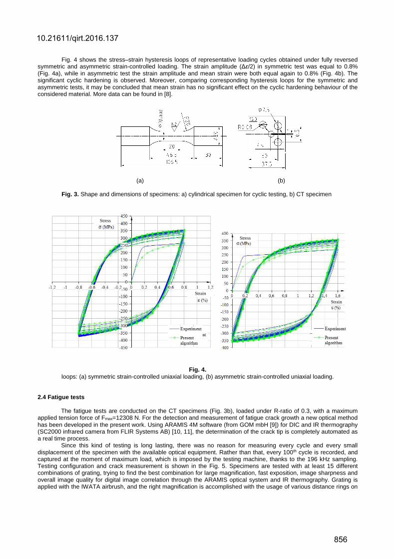
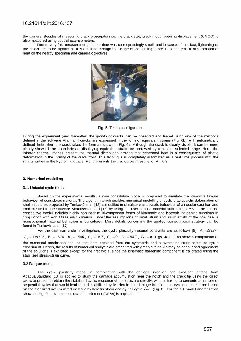
Fig. 4 shows the stress–strain hysteresis loops of representative loading cycles obtained under fully reversed symmetric and asymmetric strain-controlled loading. The strain amplitude (Δε/2) in symmetric test was equal to 0.8% (Fig. 4a), while in asymmetric test the strain amplitude and mean strain were both equal again to 0.8% (Fig. 4b). The significant cyclic hardening is observed. Moreover, comparing corresponding hysteresis loops for the symmetric and asymmetric tests, it may be concluded that mean strain has no significant effect on the cyclic hardening behaviour of the considered material. More data can be found in [8].
(a) (b)
Fig. 3. Shape and dimensions of specimens: a) cylindrical specimen for cyclic testing, b) CT specimen
Fig. 4.
loops: (a) symmetric strain-controlled uniaxial loading, (b) asymmetric strain-controlled uniaxial loading. 2.4 Fatigue tests
The fatigue tests are conducted on the CT specimens (Fig. 3b), loaded under R-ratio of 0.3, with a maximum applied tension force of Fmax=12308 N. For the detection and measurement of fatigue crack growth a new optical method has been developed in the present work. Using ARAMIS 4M software (from GOM mbH [9]) for DIC and IR thermography (SC2000 infrared camera from FLIR Systems AB) [10, 11], the determination of the crack tip is completely automated as a real time process.
Since this kind of testing is long lasting, there was no reason for measuring every cycle and every small displacement of the specimen with the available optical equipment. Rather than that, every 100th cycle is recorded, and captured at the moment of maximum load, which is imposed by the testing machine, thanks to the 196 kHz sampling. Testing configuration and crack measurement is shown in the Fig. 5. Specimens are tested with at least 15 different combinations of grating, trying to find the best combination for large magnification, fast exposition, image sharpness and overall image quality for digital image correlation through the ARAMIS optical system and IR thermography. Grating is applied with the IWATA airbrush, and the right magnification is accomplished with the usage of various distance rings on
Stress
Strain
Strain
Stress
10.21611/qirt.2016.137
856
the camera. Besides of measuring crack propagation i.e. the crack size, crack mouth opening displacement (CMOD) is also measured using special extensometers.
Due to very fast measurement, shutter time was correspondingly small, and because of that fact, lightening of the object has to be significant. It is obtained through the usage of led lighting, since it doesn’t emit a large amount of heat on the nearby specimen and camera objectives.
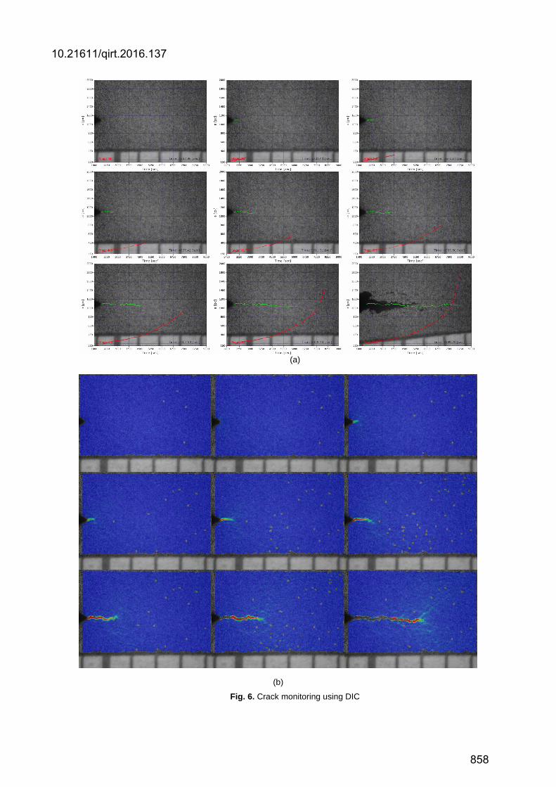
Fig. 5. Testing configuration During the experiment (and thereafter) the growth of cracks can be observed and traced using one of the methods defined in the software Aramis. If cracks are expressed in the form of equivalent strains (Fig. 6b), with automatically defined limits, then the crack takes the form as shown in Fig. 6a. Although the crack is clearly visible, it can be more clearly shown if the boundaries of displaying equivalent strain are narrowed by a custom selected range. Here, the infrared thermal images present the thermal distribution proving that generated heat is a consequence of plastic deformation in the vicinity of the crack front. This technique is completely automated as a real time process with the scripts written in the Python language. Fig. 7 presents the crack growth results for R = 0.3.
3. Numerical modelling
3.1. Uniaxial cycle tests Based on the experimental results, a new constitutive model is proposed to simulate the low-cycle fatigue
behaviour of considered material. The algorithm which enables numerical modelling of cyclic elastoplastic deformation of shell structures proposed by Tonković et al. [12] is modified to simulate elastoplastic behaviour of a nodular cast iron and implemented in the software Abaqus/Standard [13] by using the user-defined material subroutine UMAT. The applied constitutive model includes highly nonlinear multi-component forms of kinematic and isotropic hardening functions in conjunction with Von Mises yield criterion. Under the assumptions of small strain and associativity of the flow rule, a nonisothermal material behaviour is considered. More details concerning the applied computational strategy can be found in Tonković et al. [17].
For the cast iron under investigation, the cyclic plasticity material constants are as follows [8]: 1 =59927A ,
2 139713A = , 1 1574B = , 2 1566B = , 1 18.7C = , 2 0C = , 1 84.7D = , 2 0D = . Figs. 4a and 4b show a comparison of
the numerical predictions and the test data obtained from the symmetric and a symmetric strain-controlled cyclic experiment. Herein, the results of numerical analysis are presented with green circles. As may be seen, good agreement of the solutions is exhibited except for the first cycle, since the kinematic hardening component is calibrated using the stabilized stress-strain curve. 3.2 Fatigue tests
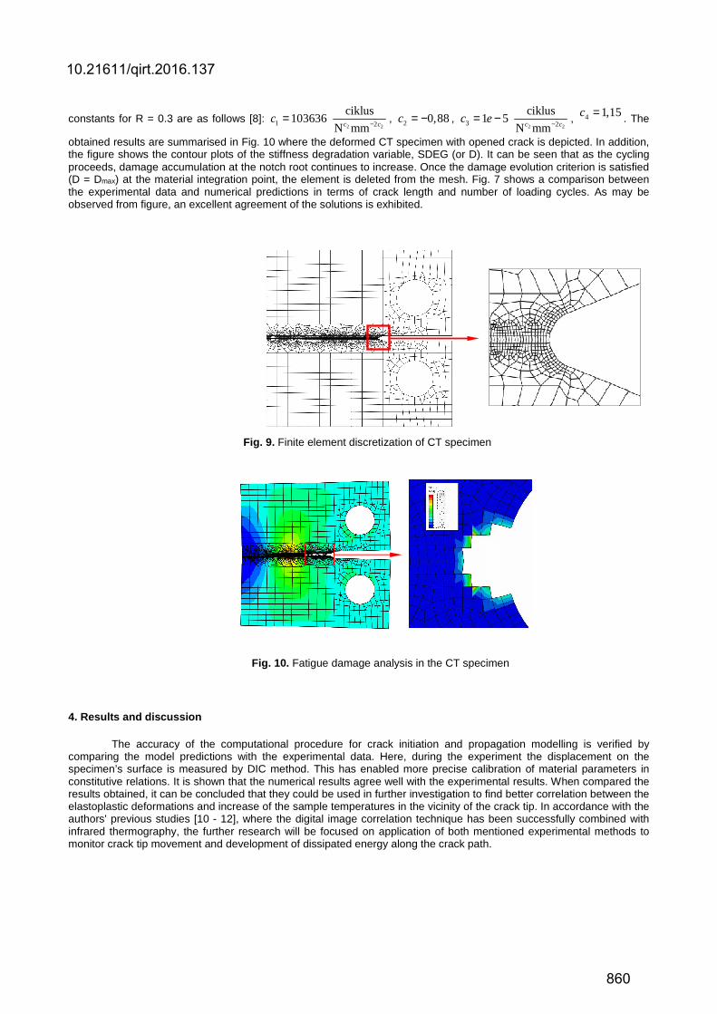
The cyclic plasticity model in combination with the damage initiation and evolution criteria from Abaqus/Standard [13] is applied to study the damage accumulation near the notch and the crack tip using the direct cyclic approach to obtain the stabilized cyclic response of the structure directly, without having to compute a number of sequential cycles that would lead to such stabilized cycle. Herein, the damage initiation and evolution criteria are based on the stabilized accumulated inelastic hysteresis strain energy per cycle, w∆ , (Fig. 8). For the CT model discretization shown in Fig. 9, a plane stress quadratic element (CPS4) is applied.
10.21611/qirt.2016.137
857
(a)
(b)
Fig. 6. Crack monitoring using DIC
10.21611/qirt.2016.137
858
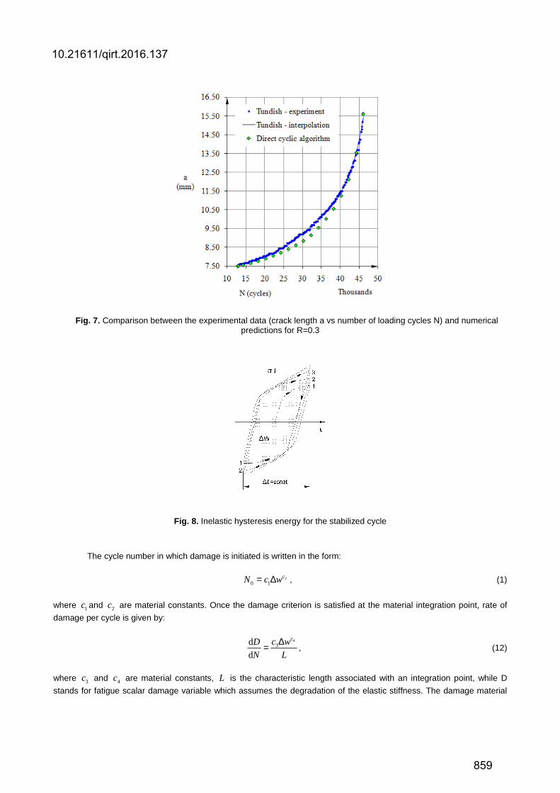
Fig. 7. Comparison between the experimental data (crack length a vs number of loading cycles N) and numerical predictions for R=0.3
Fig. 8. Inelastic hysteresis energy for the stabilized cycle
The cycle number in which damage is initiated is written in the form:
20 1
cN c w= ∆ , (1)
where 1c and 2c are material constants. Once the damage criterion is satisfied at the material integration point, rate of
damage per cycle is given by:
4
3dd
cc wD
N L
∆= , (12)
where 3c and 4c are material constants, L is the characteristic length associated with an integration point, while D
stands for fatigue scalar damage variable which assumes the degradation of the elastic stiffness. The damage material
10.21611/qirt.2016.137
859
constants for R = 0.3 are as follows [8]: 2 21 2
ciklus10363
N6
mmc cc −= , 2 0,88c = − ,
2 23 2
ciklu
mm1
s
N5
c cec −−= , 4 1,15c = . The
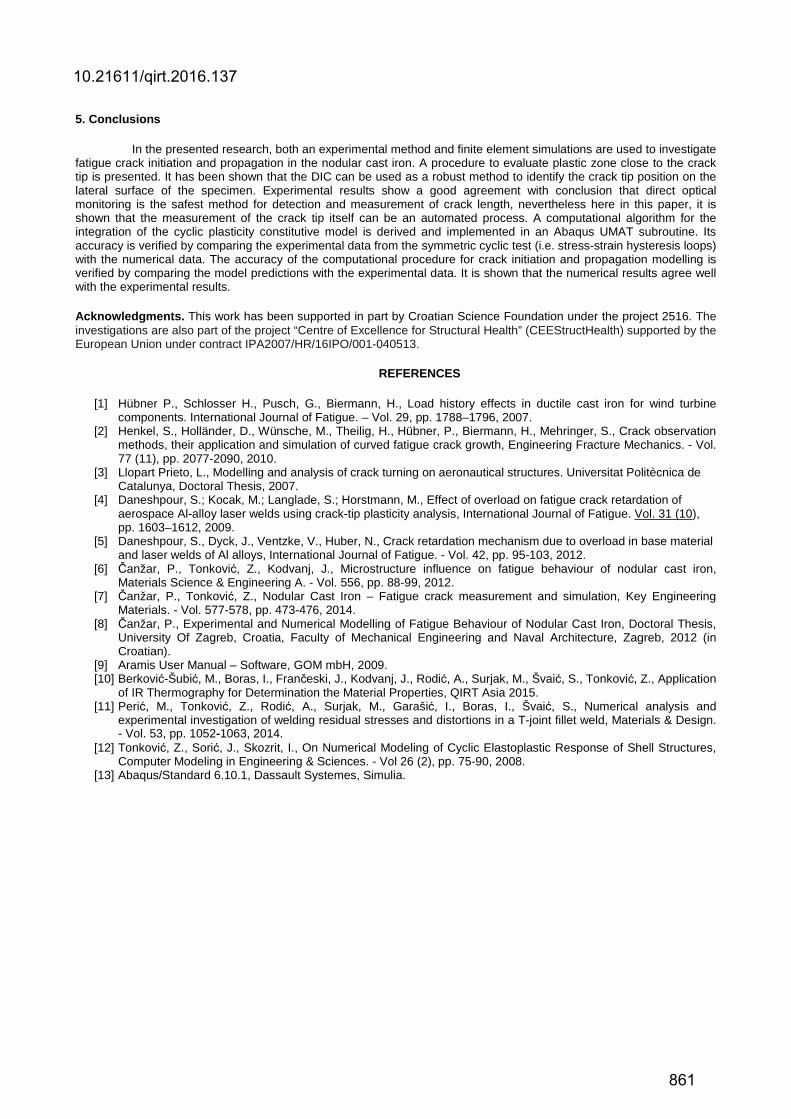
obtained results are summarised in Fig. 10 where the deformed CT specimen with opened crack is depicted. In addition, the figure shows the contour plots of the stiffness degradation variable, SDEG (or D). It can be seen that as the cycling proceeds, damage accumulation at the notch root continues to increase. Once the damage evolution criterion is satisfied (D = Dmax) at the material integration point, the element is deleted from the mesh. Fig. 7 shows a comparison between the experimental data and numerical predictions in terms of crack length and number of loading cycles. As may be observed from figure, an excellent agreement of the solutions is exhibited.
Fig. 9. Finite element discretization of CT specimen
Fig. 10. Fatigue damage analysis in the CT specimen
4. Results and discussion
The accuracy of the computational procedure for crack initiation and propagation modelling is verified by comparing the model predictions with the experimental data. Here, during the experiment the displacement on the specimen’s surface is measured by DIC method. This has enabled more precise calibration of material parameters in constitutive relations. It is shown that the numerical results agree well with the experimental results. When compared the results obtained, it can be concluded that they could be used in further investigation to find better correlation between the elastoplastic deformations and increase of the sample temperatures in the vicinity of the crack tip. In accordance with the authors' previous studies [10 - 12], where the digital image correlation technique has been successfully combined with infrared thermography, the further research will be focused on application of both mentioned experimental methods to monitor crack tip movement and development of dissipated energy along the crack path.
10.21611/qirt.2016.137
860
5. Conclusions
In the presented research, both an experimental method and finite element simulations are used to investigate fatigue crack initiation and propagation in the nodular cast iron. A procedure to evaluate plastic zone close to the crack tip is presented. It has been shown that the DIC can be used as a robust method to identify the crack tip position on the lateral surface of the specimen. Experimental results show a good agreement with conclusion that direct optical monitoring is the safest method for detection and measurement of crack length, nevertheless here in this paper, it is shown that the measurement of the crack tip itself can be an automated process. A computational algorithm for the integration of the cyclic plasticity constitutive model is derived and implemented in an Abaqus UMAT subroutine. Its accuracy is verified by comparing the experimental data from the symmetric cyclic test (i.e. stress-strain hysteresis loops) with the numerical data. The accuracy of the computational procedure for crack initiation and propagation modelling is verified by comparing the model predictions with the experimental data. It is shown that the numerical results agree well with the experimental results.
Acknowledgments. This work has been supported in part by Croatian Science Foundation under the project 2516. The investigations are also part of the project “Centre of Excellence for Structural Health” (CEEStructHealth) supported by the European Union under contract IPA2007/HR/16IPO/001-040513.
REFERENCES
[1] Hübner P., Schlosser H., Pusch, G., Biermann, H., Load history effects in ductile cast iron for wind turbine components. International Journal of Fatigue. – Vol. 29, pp. 1788–1796, 2007.
[2] Henkel, S., Holländer, D., Wünsche, M., Theilig, H., Hübner, P., Biermann, H., Mehringer, S., Crack observation methods, their application and simulation of curved fatigue crack growth, Engineering Fracture Mechanics. - Vol. 77 (11), pp. 2077-2090, 2010.
[3] Llopart Prieto, L., Modelling and analysis of crack turning on aeronautical structures. Universitat Politècnica de Catalunya, Doctoral Thesis, 2007.
[4] Daneshpour, S.; Kocak, M.; Langlade, S.; Horstmann, M., Effect of overload on fatigue crack retardation of aerospace Al-alloy laser welds using crack-tip plasticity analysis, International Journal of Fatigue. Vol. 31 (10), pp. 1603–1612, 2009.
[5] Daneshpour, S., Dyck, J., Ventzke, V., Huber, N., Crack retardation mechanism due to overload in base material and laser welds of Al alloys, International Journal of Fatigue. - Vol. 42, pp. 95-103, 2012.
[6] Čanžar, P., Tonković, Z., Kodvanj, J., Microstructure influence on fatigue behaviour of nodular cast iron, Materials Science & Engineering A. - Vol. 556, pp. 88-99, 2012.
[7] Čanžar, P., Tonković, Z., Nodular Cast Iron – Fatigue crack measurement and simulation, Key Engineering Materials. - Vol. 577-578, pp. 473-476, 2014.
[8] Čanžar, P., Experimental and Numerical Modelling of Fatigue Behaviour of Nodular Cast Iron, Doctoral Thesis, University Of Zagreb, Croatia, Faculty of Mechanical Engineering and Naval Architecture, Zagreb, 2012 (in Croatian).
[9] Aramis User Manual – Software, GOM mbH, 2009. [10] Berković-Šubić, M., Boras, I., Frančeski, J., Kodvanj, J., Rodić, A., Surjak, M., Švaić, S., Tonković, Z., Application
of IR Thermography for Determination the Material Properties, QIRT Asia 2015. [11] Perić, M., Tonković, Z., Rodić, A., Surjak, M., Garašić, I., Boras, I., Švaić, S., Numerical analysis and
experimental investigation of welding residual stresses and distortions in a T-joint fillet weld, Materials & Design. - Vol. 53, pp. 1052-1063, 2014.
[12] Tonković, Z., Sorić, J., Skozrit, I., On Numerical Modeling of Cyclic Elastoplastic Response of Shell Structures, Computer Modeling in Engineering & Sciences. - Vol 26 (2), pp. 75-90, 2008.
[13] Abaqus/Standard 6.10.1, Dassault Systemes, Simulia.
10.21611/qirt.2016.137
861