crack identification in rods and beams under uncertain
TRANSCRIPT

Crack identification in rods and beams under uncertain boundary conditions
Michele Dilenaa, Marta Fedele Dell’Ostea, Antonino Morassia,∗,
aUniversita degli Studi di Udine, Dipartimento Politecnico di Ingegneria e Architettura, via Cotonificio 114, 33100 Udine, Italy
Abstract
This paper deals with the inverse problem of identifying a crack in a rod in axial vibration with partially unknown end conditionsfrom a minimum number of resonant frequency variations. It is assumed that the crack is small and is modelled by an elastic springacting along the rod axis. A first set of results concerns a uniform bar with both ends restrained by means of elastic springs havingunknown flexibility. Under the hypothesis that the flexibility caused by the crack is small and of the same order of the flexibilityof the elastic end constraints, it is shown that the inverse problem can be formulated in terms of the variations of the first threenatural frequencies measured from the undamaged bar under ideal condition of fixed ends. It is proved that knowledge of this setof eigenfrequency variations can uniquely determine the overall flexibility induced by the end conditions, and the position (up tosymmetry) and severity of the crack, by means of closed form expressions. The identification method can be also applied to axialvibrations of uniform cantilevers with elastically restrained end condition, and to transversely vibrating uniform beams either underelastic transverse support at both ends or under cantilever end conditions. The method was verified by numerical simulation and, inthe case of the cantilever in bending vibration, by experimental data. Numerical analysis allowed to study in detail some singularsituations occurring in the mathematical formulation of the inverse problem and to test the robustness of the method to errors onthe data.
Keywords:Crack, Identification, Unknown boundary conditions, Rods, Beams, Natural frequencies, Inverse problems
1. Introduction
In this paper we are concerned with the identification of a sin-gle open crack in a beam by natural frequency measurements.This topic has been the object of extensive research in the lastthree decades and, therefore, it is not easy to draw a completebibliographic overview. Here, we limit ourselves to mentionsome of the contributions from which the interested reader cancertainly obtain more information. Adams et al. wrote at theend of ’70s the paper [1], which is considered the pioneeringwork on crack identification in beams from natural frequencydata. They proved that, in case of localized and small dam-age, the ratio between the variation of two natural frequenciesdepends on the position of the damage only, not on its inten-sity. This property was subsequently extended by Hearn andTesta [10] and used for the implementation of a damage de-tection strategy in beam-like structures. Vestroni and Capecchideveloped in a series of papers [23], [4], [24] a method for theidentification of localized damage, such as cracks or notches, inbeam structures based on the minimization of an objective func-tion constructed with the differences between the experimentalvalues of the natural frequencies and their counterparts obtained
∗Corresponding author. Phone: (+39) 0432 558739; fax: (+39) 0432558700
Email addresses: [email protected] (Michele Dilena),[email protected] (Marta Fedele Dell’Oste),[email protected] (Antonino Morassi)
from a numerical model of the system. The procedure involvesa first stage in which the damage is to be located, and a subse-quent stage in which its intensity is estimated. Sinha et al. [22]proposed simplified models of cracked beams for which appro-priate identification procedures mainly based on optimizationproblems were set. Khiem and Toan developed in [12] a methodfor the identification of multiple cracks in transversely vibrat-ing uniform beams with clamped ends. The procedure is basedon the so-called crack scanning method, recently proposed bythe same authors, and on an improved Rayleigh’s quotient typetechnique for calculating the crack induced changes in the natu-ral frequencies. The detection of concentrated damage in morecomplex structures, such as parabolic arches or frames, by mea-sured frequency variations has been approached in the papersby Pau et al. [17], [9]. Caddemi and Calio [2], [3] have re-cently developed a multiple crack damage identification proce-dure in beams based on closed form solutions of the free vibra-tion problem. The method makes use both of natural frequencydata and pointwise mode shape information.
A closer analysis of the literature leads to the conclusion thatmost of the papers on damage identification in beam structuresby frequency measurements are based on variational approach.This class of techniques allows one to deal with systems of highcomplexity (beams of variable profile under general set of endconditions, for example), but the approach has several draw-backs. They are mainly connected with the non-convexity ofthe error function and, as a consequence, with the appearanceof several local and global minima. Basic questions such as how
Preprint submitted to International Journal of Mechanical Sciences August 14, 2017
many natural frequency data are necessary to ensure uniquenessof the solution, at least in local sense, are rarely discussed in theliterature and are mainly still open.
A different line of research was initiated by Narkis in themiddle of ’90s. In his paper [15], Narkis indicated certain con-ditions on a minimal set of measured natural frequencies whichallow to determine uniquely the position of a small open crackin a uniform beam under axial or bending vibration with bothends free or pinned, respectively. Following Freund and Her-rmann [8], the crack was modelled by means of a suitable elas-tic link connecting the two portions of beam adjacent to thedamage. By linearizing the explicit expression of the character-istic equation of the damaged system in a neighborhood of theundamaged configuration, Narkis proved that the knowledge ofthe first order variation in the first two natural frequency in-duced by the crack can uniquely locate the crack by means ofclosed form expression. The result by Narkis was subsequentlyextended and generalized to other sets of end conditions byMorassi [14], who also obtained an explicit expression of theseverity of the crack in terms of a suitable pair of natural fre-quencies. The perturbative approach used by Morassi was dif-ferent from that of Narkis and, following Hearn and Testa [10],it was essentially based on the determination of an explicit ex-pression of the first order derivative of the natural frequencieswith respect to the damage severity in terms of quantities ofthe undamaged configuration of system. The uniqueness of thecrack location in symmetric beams was resolved by Dilena andMorassi [6], who suggested to include appropriate anti-resonantfrequency measurements in the input data.
The above-mentioned methods by Narkis [15], Morassi [14]and Dilena-Morassi [6] have been applied up to now to beamsin axial or bending vibration under ideal boundary conditions,namely for beams with free, pinned or clamped ends. As faras we are aware, and despite the elastic constraints often rep-resent a more realistic description of the boundary conditionsof the real structural systems, studies on the identification ofdamage in beams with elastic constraints are rather rare. Werefer, for example, to the contributions by Chondros and Di-marogonas [5], Ismail et al. [11], Sinha et al. [22]. In theseworks, the identification of damage - typically an open crack ina beam - is carried out separately from the determination of theelastic constants involved in the boundary condition descrip-tion. Chondros and Dimarogonas [5] placed the crack exactlyat the clamped end of a cantilever. Ismail et al. [11] estimatedpreliminarily the elastic support of a cantilever before proceed-ing to the identification of the damage. The same approach wasfollowed by Sinha et al. [22]. The only paper that, at the bestof our knowledge, contemplates simultaneously crack identi-fication and boundary condition identification was authored byNarkis and Elmalah [16]. The authors considered a transverselyvibrating uniform cantilever that, under operating conditions,shows a simultaneous flexibility of the clamped support and theoccurrence of an open small crack in an interior cross-section.Under the assumption that the frequency variations caused bythe weakening of the clamped end and that produced by thecrack are small and of the same order, the authors showed thatthe crack position can be determined, without knowing exactly
the boundary condition and the severity of damage, by mea-suring the variations in the first three natural frequencies of thecantilever.
In this paper we shall extend and generalize in several di-rections the results by Narkis and Elmalah. Our main goal isto determine a minimal set of natural frequency measurementsthat can guarantee the unique (where possible) determinationof both the crack position and severity in the presence of elasticend supports with unknown stiffness. As in [16], we shall as-sume that the frequency variations produced by weakening theboundary conditions and those produced by the crack are smalland of the same order. In Section 2.1 we shall consider the axialvibrations of a uniform beam with a single crack and with bothends elastically restrained with unknown stiffness. In Theorem2.1 we shall show that knowledge of the variations in the firstthree natural frequencies allows to uniquely determine the posi-tion of the crack (up to symmetry) and its severity by means ofclosed form expressions. An extension of this result to the caseof one free end and one elastically restrained end is presentedin Theorem 2.2. The case of bending vibrations for a uniformbeam with a small open crack and both ends supported by elas-tic constraints is considered in Section 2.2 (Theorem 2.3).
Our analysis is based on a suitable generalization of the crackidentification method introduced in [14]. In the case of elasti-cally restrained end conditions with unknown flexibility, how-ever, the identification procedure becomes more involved thanthe case with ideal end conditions, and the analysis requires anew, specific treatment. One distinguish feature of our resultsis the determination of closed form expressions of the unknownparameters in terms of frequency variations. Another charac-teristic is the inability to estimate the flexibility of each endelastic constraint, since only the global support flexibility canbe determined. Moreover, the analysis shows the presence offew singular situations in which one or more unknown quan-tities either cannot be identified or cannot be uniquely deter-mined. These cases generally involve special positions of thecrack and may have some relevance in the practical applicationof the method, as they may lead to inaccurate estimations of theunknown physical quantities. This is evidenced in the numeri-cal and experimental simulations illustrated in Section 3.
2. Identification: Theory
2.1. Axial vibrations of rodsThe infinitesimal, free, undamped longitudinal vibration of
a thin uniform fixed-fixed rod, with radial frequency ωn andamplitude un = un(z), is governed by the eigenvalue problem
EAu′′n + λnρun = 0, z ∈ (0, `) (1)un(0) = 0, (2)un(`) = 0. (3)
Here, E is the Young’s modulus of the material, A denotes thecross-sectional area, and ρ is the mass per unit length. Thelength of the rod is ` and λn = ω2
n is the eigenvalue associatedto the nth eigenfunction un = un(z), n ≥ 1. Hereinafter, f ′(z)denotes the first derivative of the function f = f (z).
2

Problem (1)–(3) is considered as the reference eigenvalueproblem of the supported rod. It is assumed that, during ser-vice, the rod is simultaneously affected by the degradation ofthe ideal constraint at the ends z = 0 and z = `, and by the oc-currence of localized damage - a crack - at the cross-section ofabscissa zd ∈ (0, `). The boundary condition at each end is mod-elled by means of an elastic spring reacting along the axis direc-tion connecting each end to the fixed support. The end springshave stiffness K0 > 0 at z = 0 and K` > 0 at z = `. Followingan approach commonly adopted in damage identification, thecrack at zd is assumed to remain open during vibration and it ismodelled by inserting a translational elastic spring, of stiffnessK > 0, at the damaged cross-section. The value of K can beexpressed in terms of the geometry of the cracked cross-sectionand the properties of the material, see, for example, [8].
Under the above assumptions, the free longitudinal vibrationof the cracked rod with elastically restrained ends (in brief, theperturbed rod) is governed by the eigenvalue problem
EAu′′n + λnρun = 0, z ∈ (0, zd) ∪ (zd, `), (4)K0un(0) = EAu′n(0), (5)K[[un(zd)]] = EAu′n(zd), (6)[[u′n(zd)]] = 0, (7)K`un(`) = −EAu′n(`), (8)
where (λn, un(z)) is the nth perturbed eigenpair, n ≥ 1, and[[ f (zd)]] = limz→z+
df (z) − limz→z−d f (z). The eigenvalue prob-
lem (4)–(8) coincides with the reference problem (1)–(3) as,simultaneously, K0, K` and K tend to infinity.
In this paper we shall consider rods in which the deviationof the end condition from the ideal case (e.g., perfect support)is small, namely the flexibility K−1
0 , K−1` at both the end elastic
supports is small and of the same order of smallness. More-over, also the flexibility K−1 induced by the crack is assumedto be small, and of the same order of smallness of the supportflexibility. Under the above assumptions, the inverse problemconsists in determining the flexibility of the supports, the loca-tion and severity of the damage by measuring the variations inthe first three natural frequencies of the rod from the referenceto the perturbed configuration.
By adapting the perturbation approach proposed in [13], thefirst order change in the nth eigenvalue δλn = λn − λn is givenby
δλn = −N2
n (zd)K
−N2
n (0)K0
−N2
n (`)K`
, (9)
where
Nn(z) = EAu′n(z), z ∈ (0, `), (10)
is the axial force associated to the nth eigenfunction of the un-perturbed system, normalized as
∫ `
0 ρu2n(z)dz = 1. A direct cal-
culation shows that
λn =EAρ`2 (nπ)2, un(z) =
√2ρ`
sin(nπ
z`
), n ≥ 1. (11)
By writing (9) for n = 1, 2, 3 we obtain the following system ofthree nonlinear equations in the unknowns ξ, s and F :
C1 = ξ cos2(πs) + F , (12)C2 = ξ cos2(2πs) + F , (13)C3 = ξ cos2(3πs) + F , (14)
where
ξ =EA/`
K, F =
EA`
(1
K0+
1K`
), s =
zd
`(15)
and
Cn = −δλn
2λn, Cn > 0. (16)
Two remarks on the system (12)–(14) are in order. First, therelative eigenvalue shifts δλn
λnare equally affected by the end
conditions and, in addition, the effect of the flexibility at theleft and right end is not distinguishable by frequency measure-ments. Second, if (s, ξ,F ) is a solution to (12)–(14), then also(1 − s, ξ,F ) solves (12)–(14). This latter property is a conse-quence of the symmetry of the unperturbed configuration withrespect to z = `
2 , and it suggests to assume
s ∈(0,
12
]. (17)
Our first result is as follows.
Theorem 2.1. The knowledge of {δλi}3i=1 determines uniquely
the unknowns s, ξ,F , with s satisfying (17), by means of closedform expressions.
The proof of Theorem 2.1 is based on two main steps. In Step1, the system (12)–(14) is reduced to a second degree polyno-mial equation on a suitable trigonometric function of the dam-age location. In Step 2, a careful study of the solutions of thispolynomial equation concludes the proof.
We start with Step 1. By introducing the auxiliary variable
x = cos(2πs) ∈ [−1, 1), (18)
system (12)–(14) becomes2C1 = ξ(1 + x) + 2F , (19)C2 = ξx2 + F , (20)2C3 = ξ(2x − 1)2(1 + x) + 2F . (21)
Combining the pair of equations (19)–(20) and (20)–(21), wecan eliminate the unknown F , obtaining the reduced system inthe unknowns ξ and x:{
C1 = ξ(2x + 1)(x − 1), (22)C2 = ξ4x(1 + x)(x − 1), (23)
where
C1 = 2(C2 −C1), (24)
3

C2 = 2(C3 −C1). (25)
If C1 = 0, then (22) gives x = − 12 , and the crack is uniquely
localized at
s =13. (26)
If C2 = 0, then (23) gives either x = 0 or x = −1, and the crackis localized respectively at
s =14
or s =12. (27)
In both cases, the flexibilities ξ and F can be uniquely deter-mined by (19)–(21). When C1 = 0, the two equations (19), (20)are linearly dependent and it is necessary to include the thirdequation (21) in the analysis. By inserting x = − 1
2 in (19) and(21), we obtain the linear system 2C1 =
ξ
2+ 2F , (28)
2C3 = 2ξ + 2F , (29)
which has the unique solution
ξ =43
(C3 −C1), F =4C1 −C3
3. (30)
When C2 = 0 and x = 0, from (19), (20) one finds
ξ = 2(C1 −C2), F = C2. (31)
Finally, if C2 = 0 and x = −1, then
ξ = C2 −C1, F = C1. (32)
To complete the discussion of the singular cases, let us noticethat conditions C1 = C2 = 0 can be also attained in the limitwhen s tends to 0+ or, equivalently, when x → 1−. In fact, bycontinuity, equations (22) and (23) show that both C1 and C2simultaneously tend to 0 as x → 1−, and equations (19)–(21)coincide, namely, (ξ + F ) = C1 = C2 = C3. This means thatthe individual value of ξ and F remains unknown, and only theglobal flexibility (ξ +F ) can be determined when the crack ap-proaches the support. We will see in the section of applicationsthat this condition seriously affects the accuracy of the identifi-cation.
Suppose now that C1C2 , 0. Then, the ratio C2/C1 does notdepend on ξ, e.g.,
C2
C1=
4x(1 + x)1 + 2x
, (33)
and we obtain the following second degree polynomial equationin x:
4C1x2 + 2(−C2 + 2C1)x − C2 = 0, (34)
having the two distinct real solutions
x1 =14
(C2
C1− 2
)−
√4 +
(C2
C1
)2 , (35)
x2 =14
(C2
C1− 2
)+
√4 +
(C2
C1
)2 , (36)
with x1 < x2. Expressions (35), (36) suggest that the study ofthe ratio C2
C1as a function of the damage location is useful in
the present problem. It is convenient to rewrite C1 and C2 asfunctions of the new variable
t = cos2(πs), t ∈ [0, 1), (37)
namely
C1(t) = 2ξ(1 − t)(1 − 4t), (38)
C2(t) = 16ξt(1 − t)(1 − 2t). (39)
The behavior of C1(t) and C2(t) is sketched in Figure 1 for ξ >0, whereas the graph of the quotient
C2(t)C1(t)
=8t(1 − 2t)
1 − 4t, t ∈ [0, 1), (40)
is shown in Figure 2. By (35) and (36), it is easy to see that
ifC2
C1< 0, then x1 < −1 (41)
and
ifC2
C1>
83, then x2 > 1. (42)
Therefore, in both cases only one solution of the pair {x1, x2}
is admissible, namely either x2 or x1 in case (41) or in case(42), respectively. In other words, if either s ∈
(14 ,
13
)or s ∈(
13 , s∗ = 1
πarccos
(1√
6
)' 0.366
), the position of the crack can
be uniquely determined. At this stage, the flexibilities ξ and Fcan be evaluated uniquely using, e.g., (22) and, then, (19).
Let now examine the case in which the crack is located onthe first quarter of the rod, e.g.,
s ∈(0,
14
), that is t = cos2(πs) ∈
(12, 1
), (43)
and let us try to determine the flexibility ξ of the damage byusing equation (22):
C1(t) = −ξ(1 + 2x1(t(s)))(1 − x1(t(s))), (44)
where x1 is given in (35). We want to show that the flexibilityξ in (44) turns out to be negative and, therefore, the solution x1is not admissible or, equivalently, the damage location is againdetermined uniquely in
(0, 1
4
)by using the second solution x2.
If t ∈(
12 , 1
), then Figure 1(a) shows that C1(t)
ξ< 0 in
(12 , 1
).
Then, to find the contradiction it is enough to show that theright hand side of (44) is positive, that is (note that 1 − x1 ≥ 0)
x1(t) < −12
when t ∈(
12, 1
). (45)
4

Putting η =C2(t)C1(t) , from Figure 2 we deduce that η ∈
(0, 8
3
)when
t ∈(
12 , 1
), and it is easy to show that (45) leads to
14
(η − 2 −
√4 + η2
)< −
12, (46)
that is
η <
√4 + η2, (47)
which is obviously always true. We conclude that (45) holdsand, therefore, the left hand side of (44) is negative whereas theright hand side is positive, which is the desired contradiction.
Finally, the above discussion can be repeated to prove thatalso when
s ∈(s∗,
12
), (48)
the identification of the crack position is unique. In brief, con-dition (48) implies t ∈
(0, 1
6
). Then, from Figure 2 we deduce
that η =C2(t)C1(t) ∈
(0, 8
3
), and the solution x1 leads to negative
stiffness. The proof of Theorem 2.1 is complete.
The analysis presented above can be extended to include an-other set of end conditions, which is of importance in practicalapplications, namely the clamped-free rod or cantilever. Un-der the assumptions introduced at the beginning of this section,and using the same notation, the perturbed rod is elastically re-strained (ER) at the left end at z = 0, whereas the right end, atz = `, is free. The longitudinal vibration of the cantilever witha crack of flexibility 1
K at z = zd is governed by an eigenvalueproblem as in (4)–(8), with the exception of the end conditionat z = ` which is replaced by the Neumann end condition
(uCn )′(`) = 0. (49)
Hereinafter, (λCn , u
Cn = uC
n (z)) is the nth eigenpair of the per-turbed rod, n ≥ 1. The unperturbed eigenpairs have the explicitexpression
λCn =
EAρ`2
(π
2(2n − 1)
)2, uC
n (z) =
√2ρ`
sin(π
2(2n − 1)
z`
),
(50)
n ≥ 1, and, as above, the flexibilities K−10 , K−1 are assumed to
be small and of the same order of smallness. By writing (9) forn = 1, 2, 3, we obtain the nonlinear system
CC1 = ξ cos2(
π
2s) + F C , (51)
CC2 = ξ cos2(
3π2
s) + F C , (52)
CC3 = ξ cos2(
5π2
s) + F C , (53)
where ξ, s, s ∈ (0, 1), are as in (15) and
F C =EA`
1K0, CC
n = −δλC
n
2λCn, (54)
with δλCn = λC
n − λCn , n ≥ 1. In this case, it is convenient to
introduce the position variable
xC = cos(πs) ∈ (−1, 1). (55)
Then, system (51)–(53) takes the form2CC
1 = ξ(1 + xC) + 2F C , (56)2CC
2 = ξ(1 + xC)(2xC − 1)2 + 2F C , (57)2CC
3 = ξ(1 + xC)(1 + 2xC − 4(xC)2)2 + 2F C . (58)
Subtracting (56) from (57) and (58) side by side, we obtain{CC
1 = ξ(1 + xC)((2xC − 1)2 − 1), (59)CC
2 = ξ(1 + xC)((1 + 2xC − 4(xC)2)2 − 1), (60)
where we have defined the quantities CC1 , CC
2 as
CC1 = 2(CC
2 −CC1 ), (61)
CC2 = 2(CC
3 −CC1 ). (62)
We distinguish two main cases, depending on the value ofCC
1 . If CC1 = 0, then by (59) and recalling that xC ∈ (−1, 1),
we have xC = 0, and the crack is located at mid-span, e.g.,s = 1
2 . Replacing xC = 0 in (56)–(58), it is easy to see thatonly the ”global” flexibility (ξ + 2F ) can be determined, e.g.,(ξ + 2F ) = 2CC
1 = 2CC2 = 2CC
3 , the individual values ξ andF being unknowns. Moreover, by repeating the analysis de-veloped above for the ER rod, two additional singular caseswith C1 = C2 = 0 occur as the crack approaches either the left(s → 0+, or xC → 1−) or the right (s → 1−, or xC → −1+) endof the rod. In the first case, we have CC
1 = CC2 = CC
3 = ξ + F C
and the individual value of each flexibility remains unknown,whereas in the second case we obtain CC
1 = CC2 = CC
3 = F C ,and the estimate of ξ is missing. As before, it is expected thatthis indeterminacy will influence the numerical implementationof the identification method.
We shall now consider the case CC1 , 0. Forming the quotient
CC2 /C
C1 , it turns out that the position variable xC
1 satisfies thesecond degree polynomial equation
(0 <)(xC)2 =14
+CC
2
CC1
, (63)
that is
xC1 = −
√14
+CC
2
CC1
(< 0), xC2 =
√14
+CC
2
CC1
(> 0). (64)
Now we shall prove that one of the two solutions (64) can al-ways be excluded. To show this we insert the expression of CC
1in (59), and we test it for xC = xC
1 and xC = xC2 . Recalling that
xC ∈ (−1−1), it should be noticed that the factor ((2xC−1)2−1)on the right hand side of (59) takes positive or negative valueswhen it is evaluated for xC = xC
1 or for xC = xC2 , respectively.
Therefore, if CC1 < 0, then the solution xC
1 should be excluded,since ξ must be a positive quantity. Similarly, when CC
1 > 0 thenthe solution xC
2 is discarded. In conclusion, only one solution of
5

the pair (64) remains and, since the function x = x(s) = cos(πs)is one-to-one from (0, 1) into (−1, 1), the crack is uniquely lo-calized. Finally, the flexibility ξ of the crack can be determineduniquely using (59). Once s and ξ have been uniquely identi-fied, also F C can be uniquely determined.
In conclusion, we have proved the following result for the ERcracked cantilever.
Theorem 2.2. The knowledge of {δλCi }
3i=1 determines uniquely
the unknowns s, ξ,F C , for s ∈ (0, 1) \ { 12 }, by means of closedform expressions. If s = 1
2 , then the crack can be localizeduniquely, but only the global flexibility (ξ + 2F C) can be deter-mined.
2.2. Bending vibrations of beamsThe first model that we shall consider is a uniform, thin, elas-
tic Euler-Bernoulli beam under non-perfect end supports, andwith an open crack at the cross-section of abscissa zd ∈ (0, `),where ` is the length of the beam. Each support of the beam ismodelled by inserting a vertical elastic spring, acting transver-sally with respect to the beam axis, and with stiffness K0 and K`
at the end z = 0 and z = `, respectively. The crack is modelledby inserting a localized rotational spring of stiffness K at thecracked cross-section, see, for example, [8]. The infinitesimal,undamped, free bending vibration, of radian frequency
õn and
amplitude vn = vn(z), is governed by the eigenvalue problem
EIv′′′′n − µnρvn = 0, z ∈ (0, zd) ∪ (zd, `), (65)v′′n (0) = 0, (66)K0vn(0) = −EIv′′′n (0), (67)[[vn(zd)]] = 0, (68)K[[v′n(zd)]] = EIv′′n (zd), (69)[[v′′n (zd)]] = 0, (70)[[v′′′n (zd)]] = 0, (71)K`vn(`) = EIv′′′n (`), (72)v′′n (`) = 0, (73)
where E is the Young’s modulus of the material, I is the mo-ment of inertia of the cross-section, and ρ is the mass per unitlength. The eigenpairs {µn, vn(z)}∞n=1 of the reference beam, e.g.,the beam simply supported at the ends and without damage,can be obtained as limit of the problem (65)–(73) as, simulta-neously, K0, K` and K tend to infinity. We have
µn =EIρ`4 (nπ)4, vn(z) =
√2ρ`
sin(nπ
z`
), n ≥ 1. (74)
As in previous section, we assume that the elastically supportedcracked beam is a perturbation of the reference beam, that is weassume K−1
0 , K−1` , K−1 small and of the same order of smallness.
Following [13], the first order change in the eigenvalue δµn,δµn = µn − µn, induced by the damage and by the flexibility ofthe end conditions is given by
δµn = −M2
n(zd)K
−T 2
n (0)K0
−T 2
n (`)K`
, (75)
where Mn(z) = −EIv′′n (z), Tn(z) = −EIv′′′n (z) is the bending mo-ment and the shear associated to the normalized eigenfunctionvn(z), respectively.
The diagnostic problem consists in determining the positionand the severity of the crack, and the flexibility of the supports,by minimal eigenfrequency data. Replacing the expressions ofMn(z) and Tn(z) in (75), and writing this equation for n = 1, 2, 3,we obtain
B1 = ζ sin2(πs) + G, (76)B2 = ζ sin2(2πs) + 4G, (77)B3 = ζ sin2(3πs) + 9G, (78)
where
ζ =EI/`
K, G = π2 EI
`3
(1
K0+
1K`
), s =
zd
`(79)
and
Bn = −δµn
2µn, Bn > 0. (80)
By the symmetry of the reference system, if (s, ζ,G) is a solu-tion to (76)–(78), then also (1− s, ζ,G) solves (76)–(78). There-fore, in what follows we shall assume
s ∈(0,
12
]. (81)
With the position variable
y = cos(2πs) ∈ [−1, 1), (82)
the system (76)–(78) becomes2B1 = ζ(1 − y) + 2G, (83)B2 = ζ(1 − y2) + 4G, (84)2B3 = ζ(1 − 4y3 + 3y) + 18G. (85)
Using the first two equations (83)–(84) we can express G interms of the remaining unknowns, and we obtain the reducedsystem{
B1 = ζ(1 − y)2, (86)B2 = 2ζ(1 − y)2(2 + y), (87)
where
B1 = 4B1 − B2, (88)
B2 = 9B1 − B3. (89)
If either B1 = 1 or B2 = 0, then y = 1 and the crack is locatedat s = 0. Therefore, unknowns ζ and y disappear in equations(83)–(85), and only the global boundary flexibility G can bedetermined.
If, conversely, y , 1 then we can form the quotient B2/B1and find
B2
B1= 2(2 + y), (90)
6

that is the unknown y is uniquely determined as
y =B2 − 4B1
2B1. (91)
Since the function y = y(s) = cos(2πs) is one-to-one from(0, 1
2
]to [−1, 1), the position of the crack is uniquely determined in(0, 1
2
]. Once y is known, equations (83), (84) can be used, for
example, to determine ζ and G.We have proved the following result.
Theorem 2.3. The knowledge of {δµCi }
3i=1 determines uniquely
the unknowns s, ζ,G, for s ∈(0, 1
2
], by means of closed form
expressions.
We conclude the section by considering the inverse problemposed above for a cracked cantilever with non-perfect clampedend condition at the left end z = 0. We will see that the analysisof this case is more complicated and no closed form solutionsare available.
Assume that the transverse displacement at z = 0 is hin-dered and the rotation of the end cross-section is contrasted bya rotational linearly elastic spring with stiffness K0. The crackis modelled as above. The infinitesimal bending vibration ofthe perturbed cantilever is governed by the eigenvalue problem(65)–(73), in which the end conditions (66), (67) and (72), (73)at z = 0 and z = `, respectively, are replaced by
vCn (0) = 0, K0 (vC
n )′(0) = EI (vCn )′′(0), (92)
(vCn )′′(`) = 0, (vC
n )′′′(`) = 0. (93)
The eigenvalues of the perturbed and reference beam are de-noted by {µC
n }∞n=1 and {µC
n }∞n=1, respectively. Assuming K−1
0 , K−1
small and of the same order of smallness, the analysis in [13]shows that
δµn = −(MC
n (zd))2
K−
(MCn (0))2
K0. (94)
If vCn = vC
n (z) is an eigenfunction of the reference cantilever withthe left end clamped and the right end free, then MC
n = MCn (z) =
−EI(vCn )′′(z) is an eigenfunction of the same cantilever with re-
versed end conditions. It follows that the end value (MCn (0))2
can be expressed as
(MCn (0))2 = 4µC
nEI`, (95)
where the normalization condition∫ `
0 ρ(vCn (z))2dz = 1 has been
taken into account [18]. Writing (94) for n = 1, 2, 3 we obtain
B′1 = ζ(MC
1 (s))2
µC1
+ 4G′, (96)
B′2 = ζ(MC
2 (s))2
µC2
+ 4G′, (97)
B′3 = ζ(MC
3 (s))2
µC3
+ 4G′, (98)
where ζ and s are as in (79) and
B′n = −δµC
n
µCn, G′ =
EI`K0
. (99)
Subtracting (96) from (97) and from (98), and dividing theobtained equations side-by-side, the possible positions of thecrack are the solutions of the equation
B′3 − B′1B′2 − B′1
=(MC
3 (s))2(µC3 )−1 − (MC
1 (s))2(µC1 )−1
(MC2 (s))2(µC
2 )−1 − (MC1 (s))2(µC
1 )−1≡ f (s), (100)
where s ∈ (0, 1) and the difference B′2 −B′1 is supposed not van-ish. Equation (100) can be used to locate the crack for given(measured) value of the ratio B′3−B′1
B′2−B′1. In fact, the possible po-
sitions of the crack are the abscissae of the intersection pointsbetween the function Y = f (s) and the straight line Y =
B′3−B′1B′2−B′1
.The expression of the function f (s) is universal, that is holdsfor all the uniform cantilevers of length `. However, the studyof the qualitative behavior of f (s) it seems not easy to per-form, since it involves the differences of the squared bendingmoments weighted with the inverse of eigenvalues. Postponingthe general study of f (s) to future work, in the section of appli-cations we shall investigate on the numerical solutions of (100)in some specific cases.
3. Identification: Applications
In this section, numerical applications of the identificationmethod are presented, both for longitudinal and bending vibra-tions. For the sake of simplicity, we shall consider a uniformrod or beam with unitary values of the physical parameters, i.e.,E = A = I = ` = ρ = 1. The identification problem is formu-lated by using pseudo-experimental frequency data, that is res-onant frequencies are obtained by solving the direct eigenvalueproblem in referential and perturbed configuration for differentflexibilities of the support and different position and severity ofthe crack.
Simulations performed with noise-free data shall be pre-sented in the next two subsections 3.1 and 3.2. It should benoticed, however, that even in these cases an intrinsic error ispresent on the frequency data, since the higher order terms onK−1, K−1
0 , K−1` are neglected in the first order Taylor series ap-
proximation (9).To test the robustness of the method to errors on the data, in
Subsection 3.3 the exact eigenvalue shift δλn has been perturbedas follows
δλerrn = δλn(1 + τ), (101)
where τ is a Gaussian variable with vanishing mean and stan-dard deviation σ given by σ = Π/3. Here, the number Π
is the maximum error admitted on the eigenvalue shift, andsimulations have been performed for values of Π equal to0.05, 0.10, 0.20, corresponding to errors up to 5%, 10%, 20%,respectively.
7

3.1. Axial vibrations of rods
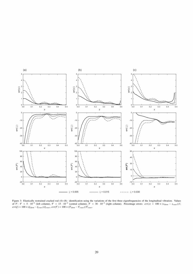
The first series of simulations has been developed for the ERcracked rod (4)–(8). Figure 3 shows the results of identifica-tion varying the position s of the crack in the interval
(0, 1
2
]and for selected flexibility values ξ, F of the crack and of theelastic support, respectively. The flexibilities ξ and F havethe same order of magnitude and each subfigure in Figure 3shows three graphs corresponding to ξ = 5 · 10−3, 15 · 10−3,30 · 10−3. The three columns of Figure 3 refer to results ob-tained for F = 5 · 10−3, 15 · 10−3, 30 · 10−3, from the left tothe right, respectively. The values of F correspond to relativeeigenvalue shifts δλn/λn, n = 1, 2, 3, of about 1%, 3%, 5% ofthe unperturbed value, respectively, whereas the three levels ofdamage severity ξ cause relative eigenvalue shifts up to 1%,3%, 5%, for the first three vibration modes. These percentagechanges are typical of small levels of damage.
Identification errors on damage position are of order of fewpoints per cent. The discrepancy increases as the crack ap-proaches the support and as the severity of the damage in-creases. The determination of the flexibilities ξ and F is lessaccurate, with errors up to 10 − 15% for damage locations ∈
(110 ,
12
). When the crack is approaching the support, the
estimates become very inaccurate and the identification of theflexibilities is seriously compromised. This behavior is a conse-quence of the singular conditions discussed in Section 2.1 and,specifically, it depends on the lack of estimates of the individualvalues of ξ and F when the crack is very closed to the elasticsupport. Numerical simulations suggest, however, that the ac-curacy improves as the flexibility F increases.
The second series of simulations concerns the cantilever rodanalyzed in the second part of Section 2.1. Figure 4 shows themain results varying the position of the crack along the beamaxis, and using the flexibility values F C, ξ as in previous Figure3. The estimate of the crack position s turns out to be quite ac-curate, with percentage errors generally less then 5−6%. Thereare two exceptions. According with the analysis of the singu-lar cases s → 0 and s → 1 of Theorem 2.2, the estimate ofthe crack position is not reliable in a neighborhood of the mid-point of the rod axis and a neighborhood of the free end of therod. Within these regions and near the clamped end, numeri-cal results show that the estimate of ξ is affected by large er-rors, which seem to prevent the use of the identification methodin the intervals
(12 −
110 ,
12 + 1
10
),(0, 1
10
)and
(8
10 , 1), at least for
the levels of damage considered here. Also the estimate of theboundary flexibility F C is affected by this pathological behav-ior, although the accuracy of identification improves as the flex-ibility F C increases.
3.2. Bending vibrations of beams
Identification for the elastically supported cracked beam(65)–(73) is discussed in this section. Due to the symmetryof the reference system, the results are presented in Figure 5 forcrack belonging to the left half of the beam axis, i.e., s ∈
(0, 1
2
].
The global flexibility G of the supports has been chosen equalto 1 ·10−4, 2 ·10−4, 6 ·10−4, corresponding to average percentagevariation δλ
λof the first three eigenvalues of about 1%, 2%, 5%
of the unperturbed values, respectively. The three levels cho-sen for the damage severity ζ, that is ζ = 5 · 10−3, 15 · 10−3,30 · 10−3, cause maximum percentage changes in the first threeeigenvalues of about 1%, 2%, 5%, respectively.
Identification errors on damage position are small and of or-der of few points in the interval
(1
10 ,12
)for values of the global
boundary flexibility G equal to 1 ·10−4 and 2 ·10−4, whereas theestimates are less accurate in the interval
(0, 1
10
), see columns
(a) and (b) in Figure 5. For G = 6 · 10−4 a good agreement isfound in a smaller interval
(320 ,
12
), see column (c) in Figure 5.
As already observed in the axial vibration cases, this behav-ior depends on the lack of estimates of the individual values ofζ and G when the crack is very closed to the elastic support. Inaddition, numerical simulations suggest that the accuracy im-proves as the ratio G/ζ between the global and the internal flex-ibilities increases. As for the determination of G and ζ, theerrors grow up to 30 − 40% for the worst cases in the interval(
320 ,
12
). In the proximity of the beam supports the estimates are
not accurate.
3.3. Sensitivity to errorsIn presence of perturbations on the eigenvalues, 1000 sim-
ulations have been performed for each level of maximum er-ror Π, as defined in Section 3. The results obtained for targetvalues s = 0.30, ξ = 5 · 10−3 and F = F C = 5 · 10−3, cor-responding to small level of damage or boundary defect, areshown in Tables 1 and 2 for axial vibrations of rods under elas-tically supported and cantilever end conditions, respectively. Itcan be seen that the estimate of the crack position is accurateeven for the maximum level of error Π = 0.20, with percentagedeviations, defined as the ratio between the standard deviationand the average of the considered parameter, less than 6%. Theidentified values of the two flexibilities are more sensitive toerrors, with deviations up to 18% and 8%, respectively for theinternal spring and the elastic constraint, with Π = 0.20.
Table 3 shows the results of the identification for the elasti-cally supported beam in bending vibration considered in Sec-tion 3.2. Target parameters are s = 0.30, ζ = 5 · 10−3 andG = 1 · 10−4. It is confirmed that the errors on the input dataare not strongly amplified by the identification method, and thedetermination of the crack position is more stable than the es-timates of the two flexibilities. As for the damage position,the percentage deviations are equal to 2%, 4%, 8% for max-imum level of error Π = 0.05, 0.10, 0.20, respectively. Thecorresponding discrepancies for both the flexibilities are almosttwice than previous values.
3.4. An experimental testIn this section we consider the cantilever in bending vibration
analyzed in the second part of Section 2.2. The experimental re-sults described in [16] are used to test the proposed identifica-tion technique. In that paper, the specimen consisted of a steeluniform beam having a rectangular cross section 30×3 mm andlength 200 mm, see Figure 6. Young’s modulus and density ofmass were equal to 206000 MPa and 7800 kg/m3, respectively.The beam was fixed at one end to a vibration device using two
8

tightening bolts. The non-perfect clamped condition was ob-tained by partially reducing the tightening torque in one bolt,whereas, to simulate an internal crack, a notch 0.1 mm wideand 0.2 mm deep was formed at a distance 40 mm (s = 0.20)from the fixed end. Dynamic tests were performed in the unper-turbed and perturbed configurations; the first three frequencieswere measured using an harmonic excitation, see Table 4.
The results of the identification are summarized in Table 5and Figure 7. In particular, the graph of the function f (s) de-fined in (100) and the horizontal straight line Y =
B′3−B′1B′2−B′1
areshown in Figure 7. The intersections between the curve and theline correspond to all the possible positions si of the crack sat-isfying the inverse problem (96)–(98). Once the positions arefound, the flexibilities of the springs can be evaluated by meansof equations (96) and (97). For the studied case, however, thesolutions s2 and s3 can be discarded, since the correspondingvalues for the flexibility of the internal spring are negative, seeTable 5. The remaining solution s1 = 0.22 is closed to the ef-fective position of the crack, with a relative error of about 2%.The result of identification coincides with the conclusions of theanalysis developed in [16] (Section 4.2), even if we were unableto follow the arguments used by the authors to conclude that thesolution of the inverse problem is unique without evaluating thevalues of the damage flexibility.
Finally, it can be observed from Figure 7 that the identifica-tion problem admits a unique solution for the position of thecrack only in a narrow interval closed to the vertical asymptotes = 0.364.
4. Conclusions
Crack identification in beams can be developed by usingchanges in the resonant frequencies between an initial, refer-ential state and a subsequent, damaged state. Results availablein the literature mainly concern with the identification of thedamage under the assumption that the boundary conditions areof ideal type (i.e., either free or perfectly fixed end conditions)and cannot change from the initial to the current configuration.
In this paper we have considered the identification of a sin-gle small open crack in a beam under elastically restrained endconditions of unknown flexibility. Under the assumption thatthe end flexibility is small and of the same order of the localizedflexibility induced by the crack, a method was developed for theidentification of the damage by using a minimum number ofnatural frequency information. Sufficient conditions allowingthe unique solution of the inverse problem have been obtainedin terms of the variations in the first three natural frequencies.Results have been obtained for initially uniform beams, eitherunder axial or bending vibration, with different sets of elasti-cally restrained end conditions. The location of the crack, itsseverity and the global flexibility induced by the end conditionshave been determined, in most cases, by means of closed formexpressions.
The method has been tested on an extended series of numeri-cal simulations performed varying the position of the crack andfor various values of the severity of the damage and flexibility
of the end supports. A validation of the method on experimen-tal data taken from [16] was also developed. Analytical resultsagree well with numerical and experimental tests.
Numerical simulations allowed to study in detail some singu-lar situation, already emerged in the mathematical treatment ofthe inverse problem, in which one or more unknown quantitieseither cannot be identified or cannot be uniquely determined,even in presence of error free data. It can be shown that thesepathological cases occur only for special positions of the crack,and are due to the truncation error in approximating the naturalfrequency variation by its first-order term in the Taylor’s expan-sion (see, for example, (9)). Numerical results show that thesecases may have some relevance in the practical application ofthe method since they may lead to inaccurate estimation of theunknown physical quantities. Generally, estimates of damageseverity and boundary flexibility suffer from major errors whenthe crack is placed close to the ends of the beam. This sug-gests that the proposed method is accurate when the crack is farenough from the ends of the beam. The crack position estimate,on the contrary, is much less affected by these errors.
This error amplification had already partially emerged in theidentification of two cracks in a simply supported uniform beamby natural frequency measurements of the bending vibration[20]. In that case, errors in crack severity estimates increasefor close cracks placed near one end of the bar. Our analy-sis shows that in case of uncertain end conditions these effectsare more important and could produce significant errors on thequantities to be identified. One way to reduce these unwantedeffects would be to remove the hypothesis of small damage andwork with generic severity of the crack by adapting the LambdaCurve Method proposed in [19]. In fact, this would avoid theintroduction of truncation errors in the Taylor’s series of theeigenvalues. The use of the Lambda Curve Method, however,is not trivial and, at present, its application to beams with elas-tically restrained end conditions is known only for bars in axialvibration with known boundary flexibility [7].
Finally, a possible extension of the proposed method is to theproblem of identification of multiple small open cracks. It islikely that the method proposed recently by Shifrin [21] in thecase of an initially uniform beam under ideal end conditionscan be useful in this regard.
Acknowledgment
The authors gratefully acknowledge the financial support ofthe National Research Project PRIN 2015TT JN95 ”Identifica-tion and monitoring of complex structural systems”.
References
[1] R.D. Adams, P. Cawley, C.J. Pye, B.J. Stone, A vibration technique fornon-destructively assessing the integrity of structures, Journal of Mechan-ical Engineering Science 20 (1978) 93–100.
[2] S. Caddemi, I. Calio, The exact explicit dynamic stiffness matrix of multi-cracked Euler-Bernoulli beam and applications to damaged frame struc-tures, Journal of Sound and Vibration 332 (2013) 3049–3063.
9
[3] S. Caddemi, I. Calio, Exact reconstruction of multiple concentrated dam-ages on beams, Acta Mechanica 225 (2014) 3137–3156.
[4] D. Capecchi, F. Vestroni, Monitoring of structural systems by using fre-quency data, Earthquake Engineering and Structural Dynamics 28 (2000)447–461.
[5] T.G. Chondros, A.D. Dimarogonas, Identification of cracks in weldedjoints of complex structures, Journal of Sound and Vibration 69(4) (1980)531–538.
[6] M. Dilena, A. Morassi, The use of antiresonances for crack detection inbeams, Journal of Sound and Vibration 276 (2004) 195–214.
[7] J. Fernandez-Saez, A. Morassi, L. Rubio, Crack identification in elasticallyrestrained vibrating rods, International Journal of Non-Linear Mechanics(in press) (2017); 10.1016/j.ijnonlinmec.2017.03.018.
[8] L.B. Freund, G. Herrmann, Dynamic fracture of a beam or plate in planebending, Journal of Applied Mechanics 76-APM-15 (1976) 112–116.
[9] A. Greco, A. Pau, Damage identification in Euler frames, Computer andStructures 92-93 (2012) 328–336.
[10] G. Hearn, R.B. Testa, Modal analysis for damage detection in structures,Journal of Structural Engineering ASCE 117 (1991) 3042–3063.
[11] F. Ismail, A. Ibrahim, H.R. Martin, Identification of fatigue cracks fromvibration testing, Journal of Sound and Vibration 140 (1990) 305-317.
[12] N.T. Khiem, L.K. Toan, A novel method for crack detection in beam-likestructures by measurements of natural frequencies, Journal of Sound andVibration 333 (2014) 4084-4103.
[13] A. Morassi, Crack-induced changes in eigenparameters of beam struc-tures. Journal of Mechanical Engineering ASCE (1993) 119:1798–1803.
[14] A. Morassi, Identification of a crack in a rod based on changes in a pair ofnatural frequencies, Journal of Sound and Vibration 242 (2001) 577–596.
[15] Y. Narkis, Identification of crack location in vibrating simply supportedbeams, Journal of Sound and Vibration 172 (1994) 549–558.
[16] Y. Narkis, E. Elmalah, Crack identification in a cantilever beam underuncertain end conditions. International Journal of Mechanical Sciences(1996) 38:499–507.
[17] A. Pau, A. Greco, F. Vestroni, Numerical and experimental detection ofconcentrated damage in a parabolic arch by measured frequency variations,Journal of Vibration and Control 17(4) (2011) 605–614.
[18] J.W.S. Rayleigh, The Theory of Sound, Vol. 1, Dover Publications, NewYork, 1945.
[19] L. Rubio, J. Fernandez-Saez, A. Morassi, Identification of an open crackin a non-uniform rod by two frequency data, International Journal of Solidsand Structures 75-76 (2015) 61–80.
[20] L. Rubio, J. Fernandez-Saez, A. Morassi, Identification of two cracks withdifferent severity in beams and rods from minimal frequency data, Journalof Vibration and Control 22 (2016) 3102–3117.
[21] E.I. Shifrin, Identification of a finite number of small cracks in a rod us-ing natural frequencies, Mechanical Systems and Signal Processing 70-71(2016) 613-624.
[22] J.K. Sinha, M.I. Friswell, S. Edwards, Simplified models for the loca-tion of cracks in beam structures using measured vibration data, Journal ofSound and Vibration 251 (2002) 13-38.
[23] F. Vestroni, D. Capecchi, Damage evaluation in cracked vibrating beamsusing experimental frequencies and finite element model, Journal of Vibra-tion and Control 2(1) (1996) 69–86.
[24] F. Vestroni, D. Capecchi, Damage detection in beam structures based onfrequency measurements, Journal of Engineering Mechanics ASCE 126(2000) 761-768.
10

Table Captions
Table 1. Results of identification for the cracked rod E = A = ` = ρ = 1 with elastically restrained ends (4)–(8) and with noisydata as in (101). Unknown parameters: s = 0.30, ξ = 5 · 10−3, F = 5 · 10−3. Percentage errors: errs = 100 × (saverage − sexact)/`,errξ = 100 × (ξaverage − ξexact)/ξexact and errF = 100 × (Faverage − Fexact)/Fexact.
Table 2. Results of identification for the cracked rod E = A = ` = ρ = 1 under cantilever end conditions and with noisy dataas in (101). Unknown parameters: s = 0.30, ξ = 5 · 10−3, F = 5 · 10−3. Percentage errors: errs = 100 × (saverage − sexact)/`,errξ = 100 × (ξaverage − ξexact)/ξexact and errF C = 100 × (F Caverage − F
Cexact)/F Cexact.
Table 3. Results of identification for the transversely vibrating beam E = I = ` = ρ = 1 with elastic supports (65)–(73) and withnoisy data as in (101). Unknown parameters: s = 0.30, ζ = 5 ·10−3, G = 1 ·10−4. Percentage errors: errs = 100× (saverage− sexact)/`,errζ = 100 × (ζaverage − ζexact)/ζexact and errG = 100 × (Gaverage − Gexact)/Gexact.
Table 4. Experimental natural frequencies and their relative variations between undamaged and damaged configurations. Datataken from [16]. Frequency variations: ∆ f = 100 × ( fUnd − fDam)/ fUnd.
Table 5. Results of damage identification for the cantilever in bending vibration. Actual damage location: zd = 40 mm.
11
Figure Captions
Figure 1. Graph of the functions C1(t) and C2(t) defined in equations (38) and (39), respectively.
Figure 2. Graph of the function C2(t)C1(t) defined in equation (40).
Figure 3. Elastically restrained cracked rod (4)–(8): identification using the variations of the first three eigenfrequencies of thelongitudinal vibration. Values of F : F = 5 · 10−3 (left column), F = 15 · 10−3 (central column), F = 30 · 10−3 (right column).Percentage errors: err(s) = 100 × (sident − sexact)/`, err(ξ) = 100 × (ξident − ξexact)/ξexact, err(F ) = 100 × (Fident − Fexact)/Fexact.
Figure 4. Elastically restrained cracked cantilever: identification using the variations of the first three eigenfrequencies of thelongitudinal vibration. Values of F C: F C = 5 · 10−3 (left column), F C = 15 · 10−3 (central column), F C = 30 · 10−3 (right column).Percentage errors: err(s) = 100× (sident− sexact)/`, err(ξ) = 100× (ξident−ξexact)/ξexact, err(F C) = 100× (F Cident−F
Cexact)/F Cexact.
Figure 5. Elastically supported cracked beam (65)–(73): identification using the variations of the first three eigenfrequencies of thebending vibration. Values of G: G = 1 · 10−4 (left column), G = 2 · 10−4 (central column), G = 6 · 10−4 (right column). Percentageerrors: err(s) = 100 × (sident − sexact)/`, err(ζ) = 100 × (ζident − ζexact)/ζexact, err(G) = 100 × (Gident − Gexact)/Gexact.
Figure 6. The cracked cantilever in bending vibration considered in [16]. (a) Schematic illustration of the experimental setup; (b)mechanical model; (c) cracked cross-section. Length in mm.
Figure 7. Results of damage identification for the cantilever in bending vibration. Actual damage location: s = 0.20.
12

Table 1: Results of identification for the cracked rod E = A = ` = ρ = 1 with elastically restrained ends (4)–(8) and with noisy data as in (101). Unknown parameters:s = 0.30, ξ = 5·10−3, F = 5·10−3. Percentage errors: errs = 100×(saverage−sexact)/`, errξ = 100×(ξaverage−ξexact)/ξexact and errF = 100×(Faverage−Fexact)/Fexact .
Π = 0.05 Π = 0.10 Π = 0.20
Stat. Property s ξ F s ξ F s ξ F
max 0.314 0.00563 0.00524 0.324 0.00632 0.00558 0.349 0.00792 0.00627min 0.290 0.00412 0.00457 0.277 0.00353 0.00430 0.249 0.00196 0.00362
average 0.301 0.00492 0.00496 0.301 0.00496 0.00494 0.301 0.00502 0.00492error (%) 0.3 −1.6 −0.8 0.3 −0.8 −1.2 0.3 0.4 −1.6std dev 0.004 0.00023 0.00010 0.007 0.00045 0.00019 0.015 0.00087 0.00039
13

Table 2: Results of identification for the cracked rod E = A = ` = ρ = 1 under cantilever end conditions and with noisy data as in (101). Unknown parameters:s = 0.30, ξ = 5 · 10−3, F = 5 · 10−3. Percentage errors: errs = 100 × (saverage − sexact)/`, errξ = 100 × (ξaverage − ξexact)/ξexact and errF C = 100 × (F Caverage −
F Cexact)/F Cexact .
Π = 0.05 Π = 0.10 Π = 0.20
Stat. Property s ξ F C s ξ F C s ξ F C
max 0.320 0.00557 0.00523 0.336 0.00633 0.00558 0.422 0.00788 0.00599min 0.292 0.00416 0.00471 0.282 0.00343 0.00445 0.264 0.00230 0.00385
average 0.304 0.00489 0.00496 0.305 0.00486 0.00497 0.305 0.00496 0.00494error (%) 1.3 −2.2 −0.8 1.7 −2.8 −0.6 1.7 −0.8 −1.2std dev 0.004 0.00022 0.00009 0.008 0.00044 0.00017 0.017 0.00087 0.00034
14

Table 3: Results of identification for the transversely vibrating beam E = I = ` = ρ = 1 with elastic supports (65)–(73) and with noisy data as in (101).Unknown parameters: s = 0.30, ζ = 5 · 10−3, G = 1 · 10−4. Percentage errors: errs = 100 × (saverage − sexact)/`, errζ = 100 × (ζaverage − ζexact)/ζexact anderrG = 100 × (Gaverage − Gexact)/Gexact .
Π = 0.05 Π = 0.10 Π = 0.20
Stat. Property s ζ G s ζ G s ζ G
max 0.320 0.00540 0.000110 0.337 0.00613 0.000116 0.368 0.01018 0.000126min 0.282 0.00446 0.000088 0.263 0.00412 0.000074 0.209 0.00359 0.000007
average 0.303 0.00488 0.000100 0.302 0.00493 0.000099 0.301 0.00503 0.000097error (%) 1.0 −2.4 0.0 0.7 −1.4 −1.0 0.3 0.6 −3.0std dev 0.006 0.00014 0.000003 0.011 0.00029 0.000006 0.023 0.00069 0.000014
15

Table 4: Experimental natural frequencies and their relative variations between undamaged and damaged configurations. Data taken from [16]. Frequency variations:∆ f = 100 × ( fUnd − fDam)/ fUnd.
Mode Undamaged Damaged[Hz] [Hz] ∆ f [%]
1 56.63 55.21 2.52 358.10 350.00 2.33 1015.60 991.40 2.4
16
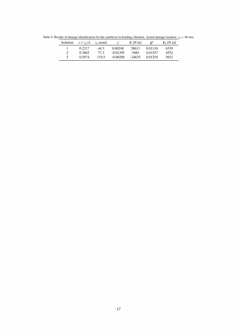
Table 5: Results of damage identification for the cantilever in bending vibration. Actual damage location: zd = 40 mm.
Solution s = zd/L zd [mm] ζ K [N m] G’ K0 [N m]
1 0.2217 44.3 0.00248 28613 0.01118 63392 0.3865 77.3 -0.01395 -5081 0.01557 45523 0.5974 119.5 -0.00288 -24635 0.01254 5652
17

C12 ξ C2
16 ξ14
12
-1.0
-0.5
0.0
0.5
1.0
0.0 0.2 0.4 0.6 0.8 1.0t
-0.10
-0.05
0.00
0.05
0.10
0.0 0.2 0.4 0.6 0.8 1.0t
Figure 1: Graph of the functions C1(t) and C2(t) defined in equations (38) and (39), respectively.
18

-6
-3
0
3
6
16
0.0 0.2 0.4 0.6 0.8 1.0
C2C1
t
14
12
83
Figure 2: Graph of the function C2(t)C1(t) defined in equation (40).
19
0
1
2
3
4
5
0.0 0.1 0.2 0.3 0.4 0.5
err(
s )
s
0
1
2
3
4
5
0.0 0.1 0.2 0.3 0.4 0.5
err(
s )
s
0
1
2
3
4
5
0.0 0.1 0.2 0.3 0.4 0.5
err(
s )
s
-40
-30
-20
-10
0
0.0 0.1 0.2 0.3 0.4 0.5
err( ξ
)
s
-40
-30
-20
-10
0
0.0 0.1 0.2 0.3 0.4 0.5
err( ξ
)
s
-40
-30
-20
-10
0
0.0 0.1 0.2 0.3 0.4 0.5
err( ξ
)
s
-20
0
20
40
60
80
100
0.0 0.1 0.2 0.3 0.4 0.5
err( F
)
s
-20
0
20
40
60
80
100
0.0 0.1 0.2 0.3 0.4 0.5
err( F
)
s
err( F
)
-15
0
15
30
45
60
0.0 0.1 0.2 0.3 0.4 0.5
err( F
)
s
ξ = 0.005 ξ = 0.015 ξ = 0.030
(a) (b) (c)
Figure 3: Elastically restrained cracked rod (4)–(8): identification using the variations of the first three eigenfrequencies of the longitudinal vibration. Valuesof F : F = 5 · 10−3 (left column), F = 15 · 10−3 (central column), F = 30 · 10−3 (right column). Percentage errors: err(s) = 100 × (sident − sexact)/`,err(ξ) = 100 × (ξident − ξexact)/ξexact , err(F ) = 100 × (Fident − Fexact)/Fexact .
20

-6
-4
-2
0
2
4
6
0.0 0.2 0.4 0.6 0.8 1.0
err(
s )
s
-6
-4
-2
0
2
4
6
0.0 0.2 0.4 0.6 0.8 1.0
err(
s )
s
-6
-4
-2
0
2
4
6
0.0 0.2 0.4 0.6 0.8 1.0
err(
s )
s
-40
-20
0
20
40
0.0 0.2 0.4 0.6 0.8 1.0
err( ξ
)
s
-40
-20
0
20
40
0.0 0.2 0.4 0.6 0.8 1.0
err( ξ
)
s
-40
-20
0
20
40
0.0 0.2 0.4 0.6 0.8 1.0
err( ξ
)
s
-15
0
15
30
45
60
0.0 0.2 0.4 0.6 0.8 1.0
err( F
C )
s
-15
0
15
30
45
60
0.0 0.2 0.4 0.6 0.8 1.0
err( F
C )
s
-15
0
15
30
45
60
0.0 0.2 0.4 0.6 0.8 1.0
err( F
C )
s
(a) (b) (c)
ξ = 0.005 ξ = 0.015 ξ = 0.030
Figure 4: Elastically restrained cracked cantilever: identification using the variations of the first three eigenfrequencies of the longitudinal vibration. Values ofF C: F C = 5 · 10−3 (left column), F C = 15 · 10−3 (central column), F C = 30 · 10−3 (right column). Percentage errors: err(s) = 100 × (sident − sexact)/`,err(ξ) = 100 × (ξident − ξexact)/ξexact , err(F C) = 100 × (F Cident − F
Cexact)/F Cexact .
21

-10
0
10
20
0.0 0.1 0.2 0.3 0.4 0.5s
-10
0
10
20
0.0 0.1 0.2 0.3 0.4 0.5s
-10
0
10
20
0.0 0.1 0.2 0.3 0.4 0.5s
-40
-20
0
20
40
0.0 0.1 0.2 0.3 0.4 0.5s
-40
-20
0
20
40
0.0 0.1 0.2 0.3 0.4 0.5s
-80
-60
-40
-20
0
0.0 0.1 0.2 0.3 0.4 0.5s
-100
-50
0
50
100
0.0 0.1 0.2 0.3 0.4 0.5s
-50
-25
0
25
50
0.0 0.1 0.2 0.3 0.4 0.5s
-20
-10
0
10
20
0.0 0.1 0.2 0.3 0.4 0.5s
(a) (b) (c)
ζ = 0.005 ζ = 0.015 ζ = 0.030
err(
s )
err( ζ
)er
r( G
)
err(
s )
err( ζ
)er
r( G
)
err(
s )
err( ζ
)er
r( G
)
Figure 5: Elastically supported cracked beam (65)–(73): identification using the variations of the first three eigenfrequencies of the bending vibration. Valuesof G: G = 1 · 10−4 (left column), G = 2 · 10−4 (central column), G = 6 · 10−4 (right column). Percentage errors: err(s) = 100 × (sident − sexact)/`, err(ζ) =
100 × (ζident − ζexact)/ζexact , err(G) = 100 × (Gident − Gexact)/Gexact .
22

(a)
(b)
40
KK 0
(c)
30
3
0.2
200
crack locationvibrationfixture
tightening bolts
Figure 6: The cracked cantilever in bending vibration considered in [16]. (a) Schematic illustration of the experimental setup; (b) mechanical model; (c) crackedcross-section. Length in mm.
23

-4
-2
0
2
4
0.0 0.2 0.4 0.6 0.8 1.0
f(s)
s
B’3-B’1B’2-B’1
s1 s2 s3
Figure 7: Results of damage identification for the cantilever in bending vibration. Actual damage location: s = 0.20.
24