cr 137824 available to the public final report (nasa-29 ... · cr 137824 available to the public...
TRANSCRIPT

CR 137824 AVAILABLE TO THE PUBLIC
FINAL REPORT
(NASA-29- 137824) EIND FUYEEL TEST BESDLTS N76-28190 3P 25 FOOT TILT ROTOR DCBINPJ A U M ~ O T B T I O N Pirial Report (Bel2 Yelicopter Co.)
€IC 35.00 CSCL 01A U n c l a s 9 1 p
- -- G3/32 47835
WIND WNNEL TEST RESULTS
OF 25-FOOT TILT ROTOR
DURING AUTOROTATION
REPORT 301-099-005
NASA CONTRACT NAS2-8580
POST OFFICE D O X 402 - FORT WORTH. T E X A S 76101 A C O M P A N V
https://ntrs.nasa.gov/search.jsp?R=19760021102 2020-05-30T03:12:04+00:00Z

WIND TUNNEL TEST RESULTS OF
25-FT. TILT ROTOR DURING
AUTOROTATION
R. L. Marr
B e l l Hel icopter Textron Report N o . 301-099-005
1 February 1976
Prepared Under Contract No . NAS2-8580
By B e l l Hel icopter Textron
F o r t Worth, Texas
For
Nat ional Aeronautics and Space Adminis t ra t ion
Ames Research Center
Mof f e t t F i e l d , C a l i f o r n i a
This d a t a is furn ished i n accordance with t h e provis ions of Contract NAS2-8580.
301-099-005

FOREWARD
This report is prepared by B e l l He l i cop te r Textron, F o r t Worth, Texas, for the Nat iona l Aeronautics and Space Administration, AmeS Research Center, Moffe t t F i e l d , C a l i f o r n i a , under Cont rac t NAS2-8580.
The Adminis t ra t ive Cont rac t ing O f f i c e r was Mr. Dennis Brown. The Technical Monitor w a s Mr. Kip Edenborough, T i l t Rotor Research A i r c r a f t P r o j e c t Off ice . w a s Mr. Robert H. Stroub, Rotor Group-Large S c a l e A e r o - dynamics Branch.
The Tunnel T e s t Engineer
301-099-005 ii

TABLE OF CONTENTS
L I S T OF ILLUSTRATIONS
L I S T OF TABLES
L I S T OF SYMBOLS
I .
11.
111.
TV.
v. V I .
V I I .
SUMMARY
INTRODUCTION
DESCRIPTION OF THE MODEL
DESCRIPTION OF TEST
DATA REDUCTION
RESULTS OF TEST
CCYCLUS IONS
L I S T OF REFERENCES
APPENDIX - TEST DATA
1. R u n Schedule
2. Instrumentation Problems
3. HSDS Data
4 . Scale Data
' Paqe
iv
vi
vii
1-1
11-1
111-1
1v-1
v-1 v1-1
v11-1
V I I I - 1
A-1
A-5
A-10
A-15
301-099-005 iii

Number
11-1
111-1
111-2
v- 1
v- 2
V I - 1
V I - 2
V I - 3
V I - 4
VI-5
V I - 6
V I - 7
VI-8
V I - 9
VI-10
V I - 1 1
V I - 1 2
V I - 13
V I - 1 4
V I - 1 5
LIST OF ILLUSTRATIONS
25-Ft. T i l t Rotor/PTR i n NASA-Ames 40- by 8O-Foot Wind Tunnel
Asymmetric Mode Natura l Frequencies
Symmetric Mode Natura l Frequencies
Spinner L i f t Tare
Spinner Drag Tare
Hover Power vs Thrus t
Hover Power C o e f f i c i e n t v s Thrus t C o e f f i c i e n t
Hover Performance Comparison
Forward F l i g h t - Thrust/Power vs C o l l e c t i v e
Forward F l i g h t Performance Comparison
Forward F l i g h t H-/Y-Force vs Collective
Forward F l i g h t Propuls ive Force
Forward F l i g h t Cyclic/Flapping v s Collective
Forward F l i g h t Blade Loads
Autoro ta t ion Thrust/Power - 60 Knots
Autorotat ion Thrust/Power - 80 Knots
Autoro ta t ion Thrust/Power - 100 Knots
Autorotat ion Thrust/Power - 80 Knots Comparison with C81
Autorotat ion Cyclic/Flapping vs C o l l e c t i v e
Autorotat ion Blade Loads - 80 Knots
Page
11-2
111-4
111-5
v-1 v-2
v1-6
v1-7
VI-a
v1-9
v1-10
v1-11
v1-12
v1-13
v1-14
v1-15
v1-16
v1-17
v1-18
v1-19
v1-20
30 1-099-00 5 i v

LIST OF ILLUSTRATIONS
(Continued)
Number
VI-16
V I - 17
V I - 10
VI-19
VI-20
V I - 2 1
Page
Autorotation Blade Loads, E f f e c t of VI-21 Lateral Cycl ic
Autorotation Minimum Power C o e f f i c i e n t - 60 Knots
VI-22
Autorotation Minimum Power Coef f i c i ent - VI-23 80 Knots
Autorotation Minimum Power C o e f f i c i e n t - VI-24 100 Knots
Maximum L i f t Coef f i c i ent VI-25
Autorotation Rate o f Descent VT-26
301-099-005 V

LIST OF TABLES
Number
111-1
111-2
111-3
A- 1
A- 2
A- 3
A- 4
Page
Rotor Descriptive Data 111-6
Propeller T e s t Stand Natural Frequencies 111-7
Instrumentation 111-8
R u n Schedule A - l
Failure Summary A-0
HSDS - Mean/Peak to Peak Data A-10
Scale Data A-15
301-099-005 vi

#LL Use 01 dirckrure d data on this pg is r u b i d to the restriction on the title m. W E U O O C r e R o o ~ n u u v
LIST OF SYMBOLS
S A l S
A 1
B1
VSND
CHS
CLR
CMXS
CMYS
CMZS
CP
t a t i o n HS DS
LONSP
A1S
LATSP
B 1s
- -
-
-
-
-
-
Descr ip t ion
Fore and a f t f lapping angle wi th r e s p e c t to t h e s h a f t ( p o s i t i v e a f t ) , deg
Lateral c y c l i c angle wi th r e s p e c t to t h e s h a f t (posi- t i v e down @ $ = goo), deg
Lateral f l app ing angle w i t h r e s p e c t t o t h e s h a f t (posi- t i v e down @ $ = 90°) , deg
Fore and a f t c y c l i c angle wit1 r e s p e c t to t h e s h a f t (posi t ivg f w d ) , deg
Speed o f sound, knots
H-force c o e f f i c i e n t / r o t o r s o l i d i t y r a t i o
H/u = H/pnn R u C
L i f t c o e f f i c i e n t / r o t o r s o l i d i t y r a t i o
cL/u = L/pnn R u
Rol l ing moment c o e f f i c i e n t / r o t o r s o l i d i t y r a t i o
Yawing moment c o e f f i c i e n t / rotor s o l i d i t y r a t i o
P i t c h i n g moment c o e f f i c i e n t / r o t o r s o l i d i t y r a t i o
Power c o e f f i c i e n t based on thc m a s t torque Cp = Q/p.rrn 2 5 R
301-099-005 vi i

I Us0 or 8irclosun ol drtr on this plpr is I subM b tho ratrlctmm on tho titk mo.
cp O Q I
cT
‘T/u
Cx/a
D
D/a ’
f
FM
H
H / B ’
L I S T OF SYMBOLS (Continued)
CPS
CPOS
CT
CTS
CXR
CYR
D
DRG6
FE
FM
FORH
FRH6
ta t i o n HS DS Descript ion
Power c o e f f i c i e n t / r o t o r 2 5 s o l i d i t y
Cp/u = Q/pnR R u
Minimum power c o e f f i c i e n t / rotor s o l i d i t y r a t io
Thrus t c o e f f i c i e n t 2 4 CT = T/paO R
Thrust c o e f f i c i e n t / r o t o r s o l i d i t y ratio
2 4 CTlU = T & n R u
Drag c o e f f i c i e n t / r o t o r s o l i d i t : r a t i o c . . L 9 = D / , R R U cX/=
Y-force c o e f f i c i e n t / r o t o r s o l i d i t y r a t i o
Cy/,, = Y/prn R 2 4
Drag, l b
Drag referred to sea l e v e l s t anda rd cond i t ions , l b
F l a t p l a t e drag a rea 2 F = D/q, f t
Figure of merit
l C P FM = .707 CT 3/2
H-force, perpendicular t o the s h a f t , l b
H-force r e f e r r e d t o s e a l e v e l s tandard cond i t ions
301-099-005 v i i i

I Use or disclosure d data on this p*lr is I r u b k t to the restriction on the titk prpc.
LIST OF SYMBOLS (Continued)
Symbol
HPMAST
HPMAS T/C '
HPB
HPLC
L
L/u'
MTIP
4
'MAST
QLC R
T
T /u
'KTS
Computer fi Scale Data
MHP
PWR6
HPB
PLC
L
LFT6
MTIP
PT
Q
S FTQ
QLC
R
THS T
TS T6
VKTS
OR
SIDE
SID6
301-099-005
Horsepower based on mast torque HP = QW550
Horsepower based on inast torque r e f e r r e d to sea l e v e l s t anda rd condi t ions .
Horsepower based on wind tunne l balance
Horsepower based on test s t a n d load cel l
L i f t , l b
L i f t r e f e r r e d t o sea l e v e l s t anda rd cond i t ions , l b
Advancing t i p Mach number 9
Data p o i n t number
Dynamic p res su re , l b / f t 2
Mast torque , f t - l b
Load ce l l to rque , f t - l b
Rotor r a d i u s , f t
Thrus t a long t h e s h a f t axis, l b
Thrus t r e f e r r e d t o sea l e v e l s t anda rd cond i t ions , l b
Tunnel speed, knots
Rotor t i p speed, VTIp=RR, ft/se
Y-force, l b
Y-force referred to sea l e v e l s tandax d con d i t u s . lb
i x

Uu w discburr d dr(r on lhir pgr h r u b k l b lha mlriclh on lhr lilk pgr.
symbol
a C
QIS
TTP CY
rl
e TIP P
n U
Wl
LIST OF SYMBOLS (Continued)
ALFC
ALFS
ALTP
EFF
THTA
ADVR
R P M
S 1 G
RHOR
THETA
- N P R
- -
~ ~~
Descr ip t ion
Control ax is angle o f a t t a c k ,
S h a f t angle of a t t a c k r e f e r r e d t o wind a x i s , deg
Tip pa th p lane angle o f a t t a c k , = a - 9 0 + a deg a
S l S TTP
Propuls ive e f f i c i e n c y based on the mast torque power r l = ( T VFps) cos a s / 5 5 0 HPmST
Tip c o l l e c t i v e angle , deg
Advance r a t i o P = V/OR
Rotor rpm, rpm
Rotor s o l i d i t y (. 0891)
A i r dens i ty r a t i o Q'= p / p o
301-099-005 X

I Use or discbsure 01 data on this pap 15 I r u b k t to the r n t r l c t h on the til* OM
I. SUMMARY
A 25-foot diameter tilt rotor was tested in the NASA-Ames 40- by 80-foot Large-Scale Wind Tunnel under NASA Contract NAS2-8580. The test confirmed the predicted autorotation capability of the XV-15 tilt rotor aircraft.
Autorotations were made at 60, 80, and 100 knots. A limited evaluation of lateral cyclic was made. Due to instrumentation, electrical, and mechanical problems, there was not time to expand the 1970 test envelope. Check runs that were made compared with the 1970 wind tunnel test at hover and 80 knots.
Test data indicate a minimum rate of descent of 2200 feet per minute at 60 knots at the XV-15 design gross weight of 13,000 pounds.
301-099-005 1-1

bELL Use or disclosure 01 data on this page is
subpct to the restriction on the title page. HeUOOCTER OWMHY
11. INTRODUCTION
This report presents the results and a brief analysis of a wind tunnel test of a 25-foot-diameter rotor designed for tilt-rotor aircraft operation as shown in Figure 11-1. Testing was accomplished to determine rotor performance and blade loads during forward flight and autorotation. The rotor tested was identical to that used on the XV-15 tilt rotor research aircraft. Testing was accomplished in the NASA-Ames 40- by 8O-foot wind tunnel. Work to prepare t\e model, testhg, and documentation were accomplished under NASA Contract NAS2-8580.
This particular rotor configuration was tested in the ARC 40- by 8O-foot wind tunnel in 1970 to obtain performance, blade loads, and dynamic stability characteristics in forward flight. Since that time, the control system design of the rotor has been changed to incorporate provisions for lateral cyclic control. In addition, the autorotation capabilities of the tilt rotor have been given considerable attention since that testing through analytical work and small scale model tests. The indications were that autorotation would be a critical area of operation and require full scale testing. Since the 1970 test, the tunnel test stand configuration was changed to accommodate autorotation shaft angles allowing the expansion of the test envelope of the tilt rotor.
Several instrumentation problems encovntered during this test, although unrelated to rotor performance, limited the forward flight testing. Limited testing was accomplished to verify the effects of lateral cyclic on the reduction of lateral flapping and blade loads. Most of the test period was spent obtaining autorotation cha-acteristics at several shaft angles and air- speeds. Comparisons made between analytical methods and test show the rotor to require higher shaft angles to autorotate than predicted.
3Q1-099-005 11-1

111. DESCRIPTION OF TEST HARDWARE
A. T i l t Rotcr and Controls
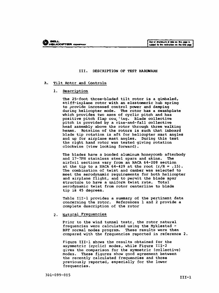
1. Descript ion
The 25-foot three-bladed tilt rotor is a gimbaled, s t i f f - i n s l a n e rotor w i t h an elastomeric hub s p r i n g to p o v i d e increased c o n t r o l power and damping during h e l i c o p t e r mode. The rotor has a swashplate which provides t w o axes of c y c l i c p i t c h and has p o s i t i v e p i t c h f l a p cou; ‘ ing , Blade c o l l e c t i v e p i t c h is provided by a r i s e -and- fa l l c o l l e c t i v e head assembly above t h e r o t o r through three walking beams. Rotat ion of the rotors is such t h a t inboard blade t i p r o t a t i o n is a f t f o r h e l i c o p t e r m a s t angles and up f o r a i r p l a n e m a s t angles , During t h i s test the r i g h t hand rotor w a s tested g iv ing r o t a t i o n clockwise (view looking forward) ,
The b lades have a bonded aluminum honeycomb af te rbody and 17-7PH s t a i n l e s s steel s p a r s and sk ins . The a i r f o i l s e c t i o n s vary from an NACA 64-208 s e c t i o n a t t h e t i p t o a NACA 64-429 a t the root ( r / R = .15). The combination of t w i s t and camber w a s s e l e c t e d to m e e t t h e aerodynamic requirements f o r both h e l i c o p t e r and a i r p l a n e f l i g h t , and t o per - i t the b lade s p a r s t r u c t u r e t o have a uniform t w i s t rate. Total aerodynamic t w i s t from rotor c e n t e r l i n e to b lade t i p is 4 5 degrees.
Table 111-1 provides a summary of the p e r t i n e n t d a t a concerning t h e r o t o r . References 1 and 2 provide a complete d e s c r i p t i o n of t h e rotor
2 . Uatura l Frequencies
Prior t o t h e wind tunnel t e s t E , the r o t o r n a t u r a l f requencies were c a l c u l a t e d using t h e Myklestad - BHT normal modes program. These r e s u l t s were then compared w i t h t h e f requencies repor ted i n r e fe rence 2 .
Figure 111-1 shows t h e r e s u l t s ob ta ined for the asymmetric ( c y c l i c ) modes, while Figure 111-2 g ives t h e comparison for t h e symmetric ( c o l l e c t i v e ) modes. These f i g u r e s show good agreement between t h e r ecen t ly c a l c u l a t e d f requencies and those previously repor ted , e s p e c i a l l y f o r t h e lower frequencies .
30 1- 09 9- 0 0 5 111-1

The fan plots i n d i c a t e t h a t t h e r e would n o t be any s e r i o u s resonance problems a t o p e r a t i n g RPM. During t h e test, t h e s m a l l resonance a t 350 RPM, dur ing run up t o rpm, w a s q u i t e e v i d e n t confirming t h e c ros s ing of the 2/rev l i n e by t h e first c y c l i c inp lane mode. Other than t h a t , no problems w e r e encountered.
B. T e s t Stand -- 1. Descr ip t ion
T e s t s t a n d used for this test w a s t h e NASA P r o p e l l e r Test Rig (PTit). The power module of t h i s test r i g c o n s i s t s of t w o 1500-HP electric motors mounted i n tandem on a frame, d r i v i n g an R-2800 engine reduct ion gearbox. The power module w a s mounted on t h e t w o 15-Lt. main s t r u t s t o t h e balance frame i n t h e 40- by 8@-foot wind tunnel . With t h e PTR i n t h i s conf igura t ion , rotor s h a f t angle-of-attack w a s changed by yawing the complete tes t r ig . A t ~ o = Oo, t h e rotor w a s i n air- p lane f l i g h t . A t $ = 90 , the rotor w a s i n h e l i c o p t e r f l i g h t . S h a f t angle-of-attack range tested w a s f r o m 3 degrees ( a i r p l a n e ) t o 110 degrees (hel icopter-auto- r o t a t i o n ) . Tunnel test s t a n d has t h e c a p a b i l i t y of varying s h a f t angle from +lo9 t o -191 degrees.
The r o t o r gearbox adap te r and m a s t case to the PTR w a s t h e same as used dur ing t h e 1970 wind tunnel test as descr ibed i n Reference 1.
2. Natural Freauencies
A v i b r a t i o n a n a l y s i s of t h e P r o p e l l e r T e s t Rig, w i t h t he 25-foot tilt rotor i n s t a l l e d , was made p r i o r t o t e s t i n g . The test s t a n d s t r u c t u r e w a s modeled on t h e NASTRAN s t r u c t u r a l a n a l y s i s and t h e n a t u r a l f requencies determined as r epor t ed i n t h e p r e - t e s t r e p o r t , Reference 3.
A v i b r a t i o n survey o f t h e actual P r o p e l l e r T e s t Rig i n s t a l l e d i n t h e tunne l w a s made wi thout a rotor to determine t h e p r i n c i p a l f requencies and damping o f t h e s t r u c t u r e and w i t h dummy weights r e p r e s e n t a t i v e of t h e r o t o r . The ro tor -of f t r a n s f e r func t ion w a s measured i n t h e l o n g i t u d i n a l , l a te ra l , and v e r t i c a l d i r e c t i o n s for yaw angles of & = Oo and 90°. Rotor weights-on r e s u l t s wereoobtained for la teral and v e r t i c a l modes a t $= 0 only. The d i r e c t i o n of shaking ( l a t e r a l o r l o n g i t u d i n a l ) is def ined wi th r e s p e c t t o t h e PTR module, n o t the kalance and wind tunnel . The test procedure and complete r e s u l t s are descr ibed i n d e t a i l i n References 4 through 6.
301-099-005 111-2

Use or diubwn a( (I(r an h i s ruli (0 Ihr ratfirtian an Ihr lit@ m.
is
C.
The measured test s t and n a t u r a l f requencies are compared to t h e c a l c u l a t e d f requencies i n Table 111-2.
Ins t rumenta t ion
Conventional ins t rumenta t ion w a s used to measure loads , control pos i t i onh , d e f l e c t i o n s , and a c c e l e r a t i o n s . Rotat ing system ins t rumenta t ion channels u t i l i z e d a 52-ring s l i p r i n g t o pfpyide 2 e x c i t a t i o n power channels and 24 data channels. Table 111-3 summarizes t h e data channels recorded. A l l channels w e r e recorded on the 40- by 80-foot wind tunne l High Speed D a t a Acquis i t ion System (HSDAS) . The HSDAS w a s used to provide d i g i t a l p r i n t o u t s of analog traces, harmonic a n a l y s i s , and c a l i b r a t i o n information. One oscillo- graph w a s used to monitor c r i t i ca l items dur ing t h e test. T h e 50-channel Peak t o Peak i n d i c a t o r u n i t w a s also used to monitor loads and v i b r a t i o n l e v e l s of a l l channels during the test. Yoke and b lade beam /chord (Sta . 8.4 and 52.5) loads along w i t h p i t c h l i n k o s c i l l a t o r y loads were monitored on an o s c i l l o s c o p e and on the model c o n t r o l console panel.
( "Or ig ina l ly only one e x c i t a t i o n power channel and 25 d a t a channels were a v a i l a b l e . High l i n e vo l t age drop between the model and recording systems and t h e loss of one d a t a channel allowed changing t o two power channels. This change reduced t h e l i n e vol tage drop to a more acceptab le l e v e l .
30 1- 09 9- 00 5 111-3


301- 099-005 7
111-5

TABLE 111-1. ROTOR DESCRIPTIVE DATA
Number o f blades
Diameter
D i s c A r e a
Blade Chord
Blade A r e a (Total 3 b lades)
S o l i d i t y
Blade A i r f o i l Sec t ion R o o t (CL mast) .15R .25R .50R .75R
1. OOR
Blade Twist Aerodynamic Geometric
H u b Precone
6 3 Hub Spring
Flapping Design Clearance
Blade I n e r t i a ( p e r b lade)
Rotor rpm/tip speed Hel icopter Airplane
3
7.62m (25 ft.)
45.6m2 (491 f t . 2 )
.356m (14 in . ) (17 i n . @ .0875R tapering to 14 i n . a t .25R
4.06m2 (43.75 ft.2
.089
NACA 64-935 NACA 64-429 NACA 64-425 NACA 64-218 NACA 64-112 NACA 64-208
45 deg 40.9 deg
2.5 deg
-15.0 deg
2700 in-lb/deg
-12/0 deg + 2 102.5 s l u g - f t
565 rpm/740 f t / s e c 4 5 8 rpm/600 f t / s e c
- ~~
301-099-005 111-6

TABLE 111-2. PROPELLER TEST STAND NATURAL FREQUENCIES
Mode
Lateral Modes Balance L a t e r a l Yaw S t r u t S ide Module Module Mast Module
Longi tudinal Modes Balance Longi tudina l S t r u t Longi tudinal Module Module
Vertical Modes Balance Balance Balance Balance Module Module Mast
Measurl R o t o r - O f f
TT-
1.73 3.14 5.56
12.3 17.2
33.3
1 . 4 4 3.54
16.2 28.6
1.29 2.41 5.55
11.7 15.9
33.1
2 .3 3.9
16.8 28.8
1.56 2.31 5.54 7.64
13.5 16.4
d - HZ Ro tor-On
( eq;;;w t . I
1.65 3.26 4.90
20.4
7.34 11.0 1 4 . 7 2 4 . 0
NASTRAN Model
(equiv. w t . )
1.43 2.09 6.68/2.52
16.9 21.6
1.80 3.99
20.24
7.90 1 2 . 8 14.45 29.03
301-099-005 111-7

TABLE 111-3. INSTRUMENTATION
Blade beamwise bending moment -Sta. 22.825 (red blade)
Blade beamwise bending moment -Sta. 52.5 (red blade)
Blade beamwise bending moment -Sta. 75.0 (red blade)
Blade beamwise bending moment -Sta. 112.5 (red blade)
Blade chordwise bending moment -Sta. 52.5 (red blade)
Blade chordwise bending moment -Sta. 75.0 (red blade)
Blade chordwise bending moment -Sta. 112.5 (red blade)
Blade torsion - Sta. 52.5 (red blade)
Blade torsion - Sta. 112.5 ( red blade)
Blade stress trailing edge -Sta. 75.0
Blade stress leading edge -Sta. 9.5
Blade stress trailing edge -Sta. 9.5
Yoke chordwise bending moment -Sta. 8.275 (red blade)
Yoke beamwise bending moment -Sta. 8.375 (red blade)
1
2
3
4
5
6
7
8
9
10
11
12
13
14
!1 No. O-Graph
3
8
20
21
23
24
Computer Notation
BB2 3
BB53
BB75
BE113
CH53
CH75
a 1 1 3
TR5 3
TR113
m 7 5
LE9
TE 9
YOKEC
YOKEB
301-099-005 111-8

TABLE 111-3. (Continued)
I t e m - Fork stress ( r e d b lade)
Fork stress (white b l ade )
Mast perpendicular bending
Mast p a r a l l e l bending
Mast torque
P i t ch l i n k a x i a l load ( red b lade )
Blade f e a t h e r i n g ( r e d b lade)
Blade f lapping ( r e d b lade)
Swashplate d r i v e r load
Co l l ec t ive s l i d e r - p a r a l l e l bending
Co l l ec t ive s l i d e r - perpendicu. l a r bending
Lateral f lapping
Fore and aft f l app ing
Co l l ec t ive tube a x i a l load
Lateral c y c l i c tube a x i a l load
Longi tcdinal c y c l i c tube a x i a l load
Co l l ec t ive p o s i t i o n
Lateral c y c l i c p o s i t i o n
Longitudi.na1 c y c l i c p o s i t i o n
Mast case v e r t i c a l acce le ra t io i ( r e fe rence t o h e l i c o p t e r ~ - 0 )
Cham SDAS
15
16
17
1 8
19
20
21
22
23
24
25
26
27
28
29
30
3 1
32
3 3
34
26
5
9
27
32
33
13
1 7
29
Computer Nota t i o n
FORK2
FORK1
MPERP
MPARA
m T Q
PLINK
PITCH
FLAP
SDRIV
CSPAB
CSPEB
LATSP
LONSP
COLAX
LATAX
LONAX
THETA
A 1 S
B 1 S
ACCV
30 1- 0 99-00 5 111-9

Use w discbsurt of data on Ihis iubirct h lha rnlriclion M lh. 11th -.
is
Mast case lateral a c c e l e r a t i o n ( r e fe rence t o h e l i c o p t e r $= 0)
Mast case f o r e / a f t a c c e l e r a t i o n ( r e fe rence t o h e l i c o p t e r $= 0 )
Forward s t r u t l a t e ra l accelera- t i o n
A f t s t r u t l a te ra l a c c e l e r a t i o n
S t r u t l ong i tud ina l a c c e l e r a t i o n
Torque-transmission load cell
Stat ic p res su re
Lateral displacement guaga-fwd
Lateral displacement guage-aft
TABLE 111-3. (Continued)
I t e m Chan is DAS
35
36
37
38
39
40
4 1
42
43
44
e l N o . O-Grap7
Computer Notat ion
ACCLA
ACCLO
SAFLA
SAALA
SAL0
QLC
PSTAT
FLADG
ALADG
LODG
30 1- 09 9- 0 0 5 111-10

mu Use w disclosure of &ta on this p*lc IS subiod to the ralriclion on the title p*)c. H~UCOPT~R-V
I V . DESCRIPTION OF TEST
Tes t ing w a s accomplished i n t h e NASA-Ames 40- by 80-foot wind tunnel dur ing 8 November 1975 through 23 November 1975 and designated T e s t No. 4 7 2 . The test w a s t o eva lua te tilt rotor a u t o r o t a t i o n c h a r a c t e r i s t i c s , t h e e f f e c t of l a te ra l c y c l i c on r o t o r f l app ing and blade loads , and t o expand t h e 1970 wind tunnel tes t envelope. Total occupawy t i m e w a s 165 hours (b lades on ready for t r a c k and ba lance ) . Ins t rumenta t ic? and mechanical problems accounted for most of the occupancy t i m e l eav ing 11.5 hours of r o t o r on t e s t i n g . A t o t a l of 128 p o i n t s was obta ined during t h i s per iod f o r a 6.9 pe rcen t u t i l i z a t i o n of a v a i l a b l e tes t t i m e .
Force and moment d a t a was measured by t h e wind tunnel balance and converted t o r o t o r t h r u s t , H-force, Y-force, and torque. A second method used t o measure torque w a s from a load ce l l on t h e t e s t s tand . The primary torque measurement w a s from a s t ra in-gage ori the r o t o r m a s t . The power c o e f f i c i e n t s and data presented i n t h i s r e p o r t use t h e mast torque s t ra in-gage because it w a s found t o be more accura t e than t h e o t h e r two methods. (The o t h e r t w o measurements were dropped from t h e scale data output . Power measurement by these methods appeared unreasonable and would n o t correlate wi th most torque measure- ments.) I n add i t ion , r o t o r rpm, c o l l e c t i v e p i t c h , c y c l i c p i t c h , and f l app ing angles were measured. For a more de ta i l ed description of d a t a measured, rotor instrument and force/angle r e l a t i o n s h i p s , see L i s t of Symbols, Sec t ion I I I . C , and i n Sec t ion V r e spec t ive ly .
The major test v a r i a b l e s were tunnel speed and s h a f t angle , see Run Schedule i n Appendix. General ly , during the runs c o l l e c t i v e p i t c h was v a r i e d while o t h e r v a r i a b l e s were he ld approximately cons tan t . Fore and a f t c y c l i c p i t c h w a s ad jus t ed t o hold fore and a f t f l app ing cons t an t a t zero. Lateral c y c l i c p i t c h w a s set to zero during most of t h e tes t , b u t w a s changed t o - 4 . 0 degrees t o ob ta in t h e e f f e c t of la teral c y c l i c on blade loads.
Basic procedure f o r t h e s t a r t of eacg run w a s t o set the c o n t r o l s t o zero ( 8 = B = A = 0 1 , br ing the r o t o r t o t h e des i r ed rpm, then b?$Kg th& tunhe1 up t o speed. As tunnel speed increased , f o r e and a f t c y c l i c ? i t c h was changed t o hold f lapping t o zero. Once t h e tunnel was on t h e desired tes t speed, c o l l e c t i v e sweeps were made so as n o t t o exceed b lade endurance l i m i t s . During t h e a u t o r o t a t i o n runs , t h e same i n i t i a l s t a r t - u p procedure was followed w i t h t h e s h a f t angle s e t a t 90 degrees w h i l e tunnel speed w a s i nc reas ing t o t he tes t speed. As s h a f t angle was increased f o r a u t o r o t a t i o n , collec-
30 1- 09 9- 0 0 5 IV-1

Use or di ichurc ol 6ata on this p&Jc is I r u b k t ta the reslrictbn on Ihr title m. -1
t i v c p i t c h was reduced to keep from s t a l l i n g the rotor. A t the s p e c i f i e d shaft a n g l e , c o l l e c t i v e sweeps were made from the lower l i m i t (eTIP = -8O) to a s e t t i n g above the bucket in t h e thrust/power curve (general ly GTIp = 0').
301-099-005 IV-2

nu MlLUCOPl-ER -*
V. DATA FtEbUCTION
Force and moment d a t a , measured on t h e wind tunne l balance were reduced using a NASA-Arne3 data reduct ion pcogram for scale data. Cont ro l p o s i t i o n s <:id test cond i t ions were thumb wheeled i n for r e fe rence . T e s t a L t a computer n o t a t i o n f o r t h e scale data i s given fn t h e L i s t of Symbols for comparison wi th the symbol as used i n t h i s report. The f o r c e and moment s i g n convention used dur ing t h i s t e s t i s shown i n Figure A-1. Scale data is given i n t h e Appendix.
Eotor loads, stress, a c c e l e r a t i o n s , and c o n t r o l p o s i t i o n s were recorded on t h e High-Speed-Data-Acquisition System. Computer no ta t ion , channel number r e fe rence , and channel d e s c r i p t i o n i s given i n Table 111-3, Sec t ion 111. Due t o t h e bulk of t h i s in format ion , the HSDAS in format ion is n o t prese'nted. The major t es t parameters recorded from t h i s system t h a t are presented i n t h i s r e p o r t are t a b u l a t e d ( c o l l e c t i v e p i t c h , c y c l i c p i t c h , f l app ing , blade loads) i n t h e Appendix.
Tare runs were made a f t e r t h e test. The on ly i t e m modified on t h e model w a s t h z nonro ta t ing f a i r i n g af PTR. I t w a s i n t e r f e r r i n g wi th t h e swashplate dr iver and had t o be c u t back p a s t t he r o t a t i n g p a r t s (approximately a 6.0 i n c h gap between t h e f a i r i n q and s p i n n e r ) . T h i s d i d n o t seem t o c k n g e t h e tare data s i g n i f i c a n t l y when compared w i t h t h e p r & i m s t a r e from t h e 1970 tes t . F igures V - 1 and V-3 compare t h e sp inne r tare used du r ing the 1 9 7 0 test w i t h t h a t of t h i s test.
301-099-005 v-1

301-099-005

I 301-099-005 v- 3 4-

V I . RESULTS OF TEST
T e s t r e s u l t s are divided i n t o three s e c t i o n s , hover performance, forward f l i g h t , and au to ro ta t ion . The first t w o conf igu ra t ions were tested to establish a c o r r e l a t i o n w i t h t h e 1970 test. Autorotat ion data w a s made available as t h e r e s u l t of t h i s test. Therefore, comparisons are made between this test and t h e 1970 test for hover and forward f i i g h t and between this test and estimates f o r au to ro ta t ion .
A. Hover Performance
Figures V I - 1 and VI -2 p r e s e n t a summary of hover t e s t i n g performed on the 25-foot rotor. Most of the hover t e s t i n g i n the wind tunnel w a s w i t h t h e s h a f t angle a t zero degrees (po in t ing upstream i n t h e tunne l ) . I n this conf igu ra t ion , the r o t o r produces enough c i r c u l a t i o n i n the tunne l t o develop a i r speeds up to 20 knots for a l o w speed axial f l i g h t conf igura t ion . As the s h a f t i s t i l t e d towards h e l i c o p t e r , hover performance w a s shown to improve.
Figure VI-3 compares the tes t hover performance ( w h i r l test) wi th t h e c a l c u l a t e d from tilt rotor s imula t ion (IFHB75), F-35, and C-81 computer programs. The math model r ep resen ta t ion for t h e IFHB75 rotor is a closed s o l u t i o n of t h e r o t o r d i s k whereas, C-81 determines rotor characteristics for twenty blade elements f o r s e v e r a l azimuth p o s i t i o n s and uses two dimensional a i r f o i l s e c t i o n a l data for f i v e radial s t a t i o n s . Induced v e l o c i t y d i s t r i b u t i o n tables w e r e used to g i v e an e l l i p t i c a l d i s t r i b u t i o n as opposed to convent ional t r i a n g u l a r d i s t r i b u t i o n . With this t y p e of d i s t r i b u t i o n , good c o r r e l a t i o n is obta ined between computed and test.
B. Forward F l i g h t
Only one forward f l i g h t condi t ion w a s ob ta ined f o r com- pa r i son w i t h the 1970 test. T h i s case w a s for a s h a f t angle of 75 degrees a t 80 knots . Comparison of rotor characteristics is shown i n Figures V I - 4 through VI-9.
Cor re l a t ion between the two tes t r e s u l t s w a s good. Hiuh c o l l e c t i v e p i t c h t e s t i n g w a s l imi t ed because of i n s t r u - mentation problems i n measuring blade loads and incidences of loos ing r o t o r c o n t r o l a t electrical connections t o t h e c o n t r o l a c t u a t o r s . Data obta ined w a s s u f f i c i e n t t o e s t ab l i sh t h a t t h e r o t o r c h a r a c t e r i s t i c s w e r e s imilar to t h e l a s t test and p r e - t e s t p red ic t ions .
30 1-0 99- 00 5 V I - 1

C. Autoro ta t ion
Autoro ta t ion c a p a b i l i t y of the tilt rotor w a s i n v e s t i g a t e d a t 60, 80, and 100 knots f o r s e v e r a l s h a f t angles . Most of the a u t o r o t a t i o n d a t a w a s t aken a t 458 r p m (600 f p s ) . T h i s is a i r p l a n e mode c r u i s e rpm. Analys is and s imula t ion tests have shown t h i s t o be a m o r e realistic a u t o r o t a t i o n rpm as opposed to t h e p r e - t e s t selected 565 rpm. amount of t e s t i n g w a s a t 535 rpm which shows t h a t autoro- t a t i o n c a p a b i l i t y tends t o decrease wi th increasirfg rpm. S ince p r e - t e s t e s t i m a t e s w e r e f o r 565 rpm, p o s t test ccnparisons are shown using IFHB75 and C81 c a l c u l a t i o n s a t 428 rpm which w e r e made a f t e r t h e test.
A l i m i t e d
F igures VI-10 through VI-12 compare the test d a t a wi th IFHB75 c a l c u l a t i o n s f o r 60, 80, and 100 knots. The computed a u t o r o t a t i o n i s shown to be o p t i m i s t i c , i.e, less s h a f t angle required to a u t o r o t a t e . The d i f f e r e n c e s tecome l a r g e r wi th i n c r e a s i n g airspeed. Maximum t h r u s t c o r r e l a t i o n between c a l c u l a t e d and test is good. These t w o effects l i m i t the a i r s p e e d range for a u t o r o t a t i o n . Wing loading dur ing a u t o r o t a t i o n needs t o be considered t o unload t h e rotor to keep f r o m s t a l l i n g the rotor. Maximum t h r u s t of the rotor a t 458 rpm is between 4900 and 4400 pounds for 60 and 100 knots r e spec t ive ly .
Figure VI-13 compares t h e test d a t a w i t h C-81 c a l c u l a t i o n s a t 80 knots. The computed a u t o r o t a t i o n i n t h i s case is shown to be s l i g h t l y conserva t ive . Shaping of t h e t h r u s t - power v a r i a t i o n is closer than computed by t h e more l i n e a r IFHB75 rotor equat ions , Again the maximum t h r u s t l i m i t comparison is good.
Figure V I - 1 4 is a comparison of f o r e / a f t c y c l i c c o n t r o l p o s i t i o n and lateral f lapping . Fo re / a f t c y c l i c c a l c u l a t e d by IFHB75 is less than t h a t computed by C-81 and the test values . Both methods compute lower la te ra l f l app ing than test. This i n d i c a t e s t h e f o r e and a f t induced v e l o c i t y d i s t r i b u t i o n to be h ighly nonl inear . I n d i c a t i o n s show it to be more so dur ing a u t o r o t a t i o n than forward f l i g h t . This is based on t h a t comparisons made i n forward f l i g h t have shown better agreement for lateral f l app ing toward s u b s t a n t i a t i n g t h e d i s t r i b u t i o n used,
Blade loads w e r e l o w and comparable t o c a l c u l a t e d as shown i n Figure VI-15. The v a r i a t i o n of loads with c o l l e c t i v e p i t c h and s h a f t angle show the test va lues to be r e l a t i v e l y cons t an t . The e f f e c t of lateral c y c l i c on blade beam bending moment is shown i n Figure VI-16 .
301-09 9- 00 5 VL-2

Hotor performance parameters o f power and l i f t c o e f f i c i e n t s dur ing a u t o r o t a t i o n are presented i n F igures VI-17 through VI-19 f o r 6 0 , 8 0 , and 100 knots r e spec t ive ly . The C
The c a l c u l a t e d va lues from IFHB75 and C-81 are compared wi th test i n Figure V I - 1 8 . The C-81 rotor shows better agree- ment than t h e IFHB75 rotor. F igure VI-20 summarizes the p ro jec t ed m a x i m u m CL/U for forward f l i g h t and a u t o r o t a t i o n conf igu ra t ions tested a t &15 degrees s h a f t ang le s from v e r t i c a l .
parameter is used as an i n d i c a t o r of rotor s ta l l . p,
Figure VI-21 summarizes t h e a u t o r o t a t i o n rate of descen t capabilities computed for the XV-15 which inc ludes the c o n t r i b u t i o n of the airframe for a gross weight of 13,000 pounds. The optimum rate of descen t w a s found to be obta ined by t i l t i n g the n a c e l l e s t o 95 degrees and p o s i t i o n i n g the f l a p s a t 4 0 degees. Rate of descen t can be held to around 2 4 0 0 fpm i f proper aircraft a t t i t u d e and collective p i t c h are maintained. These r e s u l t s are d i f f e r e n t than observed during previous tilt rotor s imula t ion tests f o r the XV-15. During the s imula t ion tests, a u t o r o t a t i o n w a s made w i t h the c o l l e c t i v e p i t c h set on t h e lower l i m i t s a t -7.5 degrees. This r e q u i r e s the r o t o r to a u t o r o t a t e on the back side of t h e thrust/power bucket . Thrust provided by the rotor is lower and i n order t o t r i m the aircraft , t h e w i n g is ope ra t ing very n e a r maximum l i f t . This combina- t i o n r e s u l t s i n higher s i n k rates. Autoro ta t ion test r e s u l t s show t h a t t h e optimum c o l l e c t i v e p i t c h s e t t i n g f o r t h e tilt rotor to be about -5 .0 degrees, which allows the rotor to ope ra t e on t h e f r o n t side of t h e thrust/power bucket. This inc reases t h e t h r u s t provided by the rotor and reduces the l i f t r equ i r ed by t h e airframe.
As shown i n t h e previous f i g u r e s , the s h a f t angle r equ i r ed from tes t w a s g r e a t e r than ca l cu la t ed . Autoro ta t ion a t s h a f t angles around 105 degrees and w i t h t h e n a c e l l e s a t 90 degrees would gene ra l ly r e q u i r e f l y i n g beyond wing s t a l l . T i l t i n g t h e nacelles t o 95 degrees reduces t h e wing angle of at tack and rate of descent. Raising the f l a p s would tend to s t a l l o u t t h e rotor a t l o w rpm or r e q u i r e h ighe r rpm f o r a u t o r o t a t i o n r e s u l t i n g i n h ighe r s i n k rates and reduced f l a r e c a p a b i l i t y . Equations used t o estimate t h e a u t o r o t a t i o n rate of descent shown i n Figure V I - 2 1 and a sample c a l c u l a t i o n is given below.
301-099-005 VJ-3

Autoro ta t ion rates of descent w e r e c a l c u l a t e d us ing t h e following simplified method to account f o r t h e a i r f rame.
L i f t = TmmR s i n as + L~~~~
Drag =-TmTOR cos Q S + DAIRFRAME
"S = "F +iN
Thrus t of the rotor is obta ined from Figures VI-10 through VI-12 a t s h a f t ang le s for HP = 0 and HP = -20 (account ing f o r accessory and t ransmission d r i v e ) . L i f t and drag of t h e airframe are obta ined from Reference 7.
For V = 80 k t s , iN = 9S0, 6, = 40°, HP = -20, Qs = 107O
= -50 and %I,
= (3450) (2 ) = 6900 pounds TROTOR
a = 105 - 95 = 10 deg
L i f t = 6900 s i n 107+ 1.32 (21.69) (181) Drag -6900 cos 107 + .45 (21.69) (181)
-*. Y = t a n -' (3934/12780) = 1 7 . 1 degrees
R/D = 101.26(80) s i n 17.1 = 2383 fpm
F + 1000(1)=12780
+ 150(')=3934
@ aF = 10 deg = 1.32 ( U C LWING C @ aF = 10 deg = . 45
D~~~~
1000 pounds approximate l i f t of fu se l age arid empennage. 150 pounds approximate drac, af fu se l age and empennage.
30 1- 09 9- 0 0 5 V I - 4

I Use or Oi%bsuro of W m this page is I subkt b the restriction an tho titlo me.
Rate of descent f o r a u t o r o t a t i o n w a s determined f o r t h e optimum c o l l e c t i v e p i t c h and s h a f t angle to t r i m t h e a i r c r a f t a t 458 rpm (600 fps) and 13000 pounds. A t a s p e c i f i c collectivc- p i t c h angle , rpm and s h a f t angle would change f o r a t r i m condi t ion . The rates of descent f o r t h e collective p i t c h set on t h e lower l i m i t (0, = - 8 . 0 degrees) is also presented. These values may not 6e the same as the a c t u a l a i r c r a f t ope ra t ing a t d i f f e r e n t g ross weight, rpm, or c o l l e c t i v e p i t c h s e t t i n g s . This is l ikewise t h e case f o r t he s imula t ion test r e s u l t s which w a s a t a lower rpm.
301-099-005 VI-5

I
- w
. -
3- . --.
!;
5 301-099-005 V I - 6 -&- d r- c

~. --*. ** .*.4 1' , F i g u r e V I - 2 i : I
--.. ~ . * . ( . . . . . I . . . . l . _ . . I I 1 . .

I
I
t I . .
! ' t ! ! : .; . i... . . -+. ..
I
1 - , .
I L , I
i !

1 4 I
! 4 ,
1:. . * /
i ! I
.. - !
i
! ... I .
-- ._ . .
J
i
4 _ .
i . -
- 1 - i I . ,
- 7 - t . .
--I.- -1..
I. ! .. .e .
. ....... i !
...
. . . I
.... 1 !
_ I / I
' I
; I
1 . . I I
. .
I
i *- I
i i
V I - 9 30 1- 09 9- 00 5 1 .~

L (I n I ,1 ! .
... .
. . I
. . I
.. - .
_.__ ----
301-099-005
i
VI-10
i
ai

I
i 1 301-099-005
I 2 -
! 1
!
I5 7 . .. . .
i . I -
1 i
.. -
1 . I I
!- I . ...
! I.
i
! I
. ~ _ _ -
i - . .!...
! I I
1 .I . i-
!
f
1 :
-
-1 Figure V I - 6 {
VI- 11

i t
1 I-
*: I
L .i
1 .
I
__ ' i , i
....
i. .
. - I - . rt- - t-. , I -
1 -{ :: .
-L
1; -
I
. .
- 1
i - i
.....
. I i . -.. !
- I ._ 1
-* -
... 1 .. !
i i i
_ i
. . I
- . .
!
I
I
,
.~
......
-.. .. i
f
1 I
.... !
._ .
. _ _
. . -
I
i e -
i E /
I - I I
SF . - 1
.- 1 ! __ .. i
f i i - . I-
I I
.........
i . . . . , .
. .- .
I i j
I... ; - . ! i .
I - .-
i I
-. .
i i : I :
- I I 1 . 1
j j ;
L . L . . e
. . e-
l . I

V I - 1 3 301-099-005 i

f
V I - 1 4
t \

5 I
I-
- - t r
1
* 301-099-005 VI-15
- = . - -- . . ..:~

i
- -
I
!
i
i
i I
301-099-005 -4
L . ,
VI-16

. -.
= -
VI-17 301-099-005
1c! .==. )- . , k ,

301-099-005 VI-18

301-099-005 V I - l O

, , ' Figure V I - 1 5
301- 099- 005 V f - 2 0

. .
301-099-005

301-099-005
ton oar7

301-099-005
1172 M a 1 7
.. ..... . . . . . . . .
. . .... . T ..........
. . . . . . . . ..--A --I- --c . . . . . . . . .- . . .. I . . i . I
-j-- t
VI-23

301-099-005 7 @ 7 2 (10117

I
I yo2
0
301-099-005
I -- I
1 i

I I
1.
I I
; I
I I
i 1. ;.
1 1
i
!
k.
VI-26 3 30 1-09 9- 005

VII. CONCLUSIONS AND RECOI"4ENDATIONS
Although all test objectives were not accomplished, auto- rotation capability of the tilt rotor was confinned. Autorotation capability was shown for variations in airsneed and rpm. Limited analysis indicates that the autorotation rates of descent of the XV-15 will be similar to predicted and that demonstrated during the tilt rotor simulation tests, but the shaft angles required would be approximately 5 degrees greater than pretest predictions. cyclic to reduce lateral rlapping and blade loads was demonstrated. Rotor characteristics were similar to predicted, but indications are refinements need to be made to the drag representation in the rotor math models at low collective pitch settings before additional analysis is made. It is recommended that the rotor math model for the tilt rotor simulation be improved to better represent the tilt rotor autorotation characteristics for analysis of the optircuxn autorotation configuration, i.e. nacelle incidence, flap setting, r p m , collective setting, and airspeed.
Use of lateral
301-099-005 VII-1

- e -- VIII. REFERENCES
1. Advancement of Propro tor Technology Task I1 - Wind-Tunnel Test- Resufts (NASA Contract NAS2-5386) BHC Report 300-099-tO4, NASA Contractor Report CR 114363, 30 Septem- ber 1471.
2. V/STOL T i l t Rotor Research Aircraf t , BHC Report 301-199-003, Volume 3.
3. Marr, R o g e r , " T e s t Plan f o r a 25-Foot T i l t Rotor T e s t i n the ARC 40- by 8O-Foot Wind Tunnel," 6 May 1975.
4. Zohnson, Wayne, "Shake T e s t of a P r o p e l l e r T e s t f i g i n t h e 40- by 8O-~oot Wind Tunnel," November 1975.
5. Johnson, Wayne and Biggers, James C., "Shake T e s t of Rotor T e s t Apparatus i n t h e 40- by 8O-~oot Wind Tunnel," NASA TMX-62,418, February 1975.
6. Johnson, Wayne and Biggers, James C., "Shake T e s t of Rotor T e s t Apparatus wi th Balance D a m p e r s i n t h e 40- by 8O-Foot Wind Tunnel," NASA TMX-62,470, J u l y 1975.
7. Marr, Roger, V/STOL T i l t Rotor Study - Volume V - A Mathematical Model f o r Real Time F l i g h t Simulat ion of t h e B e l l Model 301 T i l t Rotor Research A i r c r a f t , BHC Report 301-099-001, NASA Contractor Report CR 114614, Apr i l 13, 1973, Revision F.
301-099-005 WIT-1

fl I '0:' I
I 0
j l -
..

I I
0
, o
i .
. . . ? .
! , . . .
. ,
, ' a
i
1
i i I
i f t
i I
1 1 I
I
. I
i !
i r I
ii 301-099-005

. .
' . I . . c
-
F

1 : , ' ' j ; " . I .
I
!
i
i I
i i
I
I 1
i
I
1 I
I
I i i
I I
I
i I
I I
I i I -i
I
I
I
! I f
I f
1 1 ! I I I I
I I
i I I !
! I
I !
i I 1
; I / / i i
i ! i 1 I
1 1 i
I
I I
I I
I
I ' !
1
!
i
1 I i
!
i ! ! I
I i
I
!
f
j 1 .
/ I
I
! i i i
/ I ' i l ,
1 I I .
1 1 1

TEST INSTRUMENTATION PROBLEMS
Severa l ins t rumenta t ion problems w e r e encountered dur ing t h e 25-foot powered test a t NASA-Arnes 40- by 80-Foot Wind Tunnel d u r i n g November 1975. I t w a s f e l t t h a t a d i scuss ion of these problems and p o s s i b l e ways that they can be avoided on f u t u r e tests be included i n this repor t . Tab le A-2 summarizes the problems encountered dur ing t h e test. f a l l i n t o s i x ( 6 ) categories as follows:
These problems g e n e r a l l y
I. C e n t r i f u s a l Force on Connectors
Connectors w e r e placed i n t h e r o t a t i n g system to expedite any tes t p a r t replacement, A s the test w a s run, the c e n t r i f u g a l force on t h e i r mass caused s t r a i n on the Are, and even tua l ly caused w i r e f a i l u r e . When t h e cause of these f a i l u r e s became ev iden t , the connectors w e r e removed and the w i r e s w e r e s p l i c e d toge the r , I n the f u t u r e , connectors w i l l be used only a t l o c a t i o n where they can be bonded (rotor blades, hub, etc,) or t i e d secu re ly and taped ( p i t c h links, c y c l i c tubes , etc.) . 11. Cent r i fuga l Force on Wire Loops
Since the s l i p r i n g w i r e s must be routed o u t of the hub assembly to the top of the c o l l e c t i v e head, a loop of w i r e s w a s formed. Th i s loop w a s necessary due t o t h e motion of the c o l l e c t i v e head w i t h r e s p e c t t o t h e hub assembly as blade p i t c h w a s i nc reased and decreased. Cen t r i fuga l force on t h i s loop caused broken w i r e s on s e v e r a l occas ions due t o f a t i g u e . One s o l u t i o n for t h i s problem would be to rou te a s t r a i n relief w i r e a long w i t h the bundle t o t a k e t h i s s t r a i n away from t h e s i g n a l w i r e s . A program t o test t h e e f f e c t s of c e n t r i f u g a l f o r c e might need t o be i n i t i a t e d t o determine proper s t r a i n relief techniques on w i r e s . Another p o s s i b l e s o l u t i o n t o this problem could be a redesign of t h e c o l l e c t i v e head ( l i k e t h e XV-15 f l i g h t hardware). T h i s would al low the use of t h e f l i g h t test s l i p r i n g assembly and would e l imina te t h e loop completely as t h e w i r e s would be routed i n s i d e t h e c o l l e c t i v e tube t o t h e s l i p r ing .
The s l i p r i n a would be mounted on the t o p of t h e collective head, not below t h e swashplate as it w a s dur ing t h i s model test . 111. Motion Between Model and Cowlins
A new d r i v e motor s t and was used f o r this test. Between t h e motor s t a n d and t h e o u t e r cowling e x i s t e d a poss ib l e *2.5 inches
30 1- 0 9 9- 00 5 A- 5

of motion. To provide mechanical c l e a r a n c e s , t h e f r o n t 6 inches were trimed from t h e o u t e r cowling. For ease of access, t h e ins t rumenta t ion J-boxes w e r e mounted on t h e cowling, n o t on t h e m o d e l . The v i b r a t i o n l e v e l s on t h i s outer cowling w e r e very high and t h e wind turbulence i n s i d e t h e cowling (wi th the forward p o r t i o n c u t o f f ) w a s also high. The model-to-cowling motion, t h e cowling v i b r a t i o n and t h e wind turbulence each con t r ibu ted to c a u s e many broken w i r e s due t o f a t i g u e . P o s s i b l e s o l u t i o n s to t h e s e problems are: mounting of t h e J-boxes on t h e model where a more stable mount can be made; making a better nose cowling to reduce wind turbulence i n s i d e the nose cowling; improved cable r o u t i n g and better secu r ing techniques to c o n t r o l cable motion ( e l imina t ing f a t i g u e p o i n t s ) ; l a r g e r gage w i r e f o r better f a t i q u e c h a r a c t e r i s t i c s .
IV. S l i p Ring W i r e Routing
The s l i p r i n g system f o r this model has been a source of trouble dur ing a l l tests on which it has been used. The s l i p r i n g i t s e l f is n o t the problem. The problem is t h e means by which t h e w i r e s must be routed from t h e slip r i n g to the r o t a t i n g system. A l l 52 wires must pas s through t w o &-inch ho le s a f t e r being fanned through t h e teeth of the m a s t s p l i n e s . This is necessary s i n c e t h e wires must pas s under t h e nonro ta t ing s e c t i o n (hub s p r i n g ) of t h e rotor assembly. Due to this des ign , there is no s o l u t i o n to t h i s problem except t hose s o l u t i o n s d iscussed earlier (use of f l i g h t s l i p r i n g wi th redes ign of c o l l e c t i v e head; s t r a i n relief w i r e s ) .
V. Shor t C a l i b r a t i o n S teps
During the checkout of t h e ins t rumenta t ion fol lowing i n s t a l l a t i o n i n t h e t u n n e l , t w o channels w e r e found to have s h o r t c a l i b r a t i o n s t e p s . The short c a l i b r a t i o n s t e p s caused t h e loads d a t a t o be incorrect a t t h e s e two l oca t ions . A f t e r much checking, by both NASA and BHT personnel , t h e problem w a s found t o be t w o p i n s sho r t ed i n one of t h e NASA c-mnectors under t h e tunnel f l o o r . T h i s short had no: shown up i n previous tests because of t h e s i x w i r - system t h a t the NASA tunne l uses. For t h i s tes t a common power supply was used due to t h e l imi t ed amount of r i n g s i n the s l i p r i n g . Once t h e shor t w a s c l e a r e d , a check c a l i b r a t i o n of t h e sys t em, using known we igh t s a t a given s t a t i o n , proved the d a t a t o be c o r r e c t .
301-099-005 A- 6

V I . Random 60 Hz Noise
During t h e e n t i r e tes t , the r o t a t i n g channels were plagued by random 60 Hz noise . Many checks and many a t tempts were made to f i n d the source arid a cu re for the problem, b u t none w a s found. I t is now thought t h a t the i n t e r f a c e of the common bridge vo l t age for the r o t a t i n g channels w i t h t he tunne l s i g n a l condi t ion ing w a s t h e sole or major cause of the problem. For any future tests using this common b r idge vo l t age , a test s e t u p should be made to allow i n s e r t i n g dummy b r idges i n t o the system a t va r ious p o i n t s t o determine where the no i se i s being i n s e r t e d i n t o t h e system. When the l o c a t i o n of e n t r y of t h e n o i s e is found, the cause should be e a s i l y found.
30 1-09 9- 00 5 A- 7

c
.- ..-
I . 1. . -.
301-099-005
i, -
i- i-- I -- I
4 * -
I
._ I
, i / ' i L
. . 1
A- 0


f 301-09P--30S I I
! A-10

4 i Y Z ' ' 3
. A-11 t

.
N4a. N o
? i r4 1
i
I
I
c
*
c-
73% - 7 3 6 5 . - 7182 - 7553 - 76Y'5/ .
7927 3 3 8 3 , -
3571 , - 7832 - 6 9 7 2 . - 797J - 8019 - 5 5 6 2 . - 5873, - 6 / 9 4 - 6a8( --
7 3 1 3 - 62/q .- 7 9 b 6 -
'2 *3z . T 3 . 7 2 . -6*'2,
72 , - / , O b .
.'r"B .-S.&, . - / . 9 B
. -/. 88
-7.87, #V/ .-3,8 ,251 */A . e37 . / . o s , I40 :-/.97,
301-099-005 A-12
L

; No
: /&
301-099-005 t

--- I'
i
:
I
301-099-005 A-14

0 0
O!
i O f
c e!. 52% O H
0 (YCI 09- e901 o m 0 0 E o!
-mi
o o m i"
i +ii
r;l Q
A-15
301-099-005

I-- I
1" I
I f
i'q
"1
A- 16
301-099-005

I . I .I -. I
t l r ) -0 0 on .
0 i I
O O t
301-099-005

I
i
I I I
i
4 I
4
1 . m
1
I
I . 1 .. I
f -,= c * y e'-
! a! c
I
C C f Z t r a m > E >
. I *. -- oL 0 010 9
a 0 0 - o n
n'oa To-
0 0 0 7 - 0'0 r.
0:- 0 O W 0
coo
- 301-099-005

I
A-19
301-09 9-00 S -- -

4
a 4
, a a
1 a a
1 Q I
a
0 4
. 0 I
. 0 I
a 0 I
. 0 0
I a-r I I, 7 - !
iryo c
a 2
1 L
1* -0 c n n m 0 0 0 .
m w m
A-20
301-099-005 r____ .~

0 m
e
d 0 8
W
d :i a
0 0
d 0 8
0 e
2 ' 2
B Z ? O O P a u o o w N w 3, z L
- 0 - n o m
I '
A - 2 1
301-099-005

I nllP
r 21: 0 PI c nla
Use or dirckurc ol $8tl on this p*lr is r u b k t to thr rnlrklion on the tilk ~lpc.
A-22
301-099-005

0 m
0
0 0
0 0 m
. 0 8
. 0 0
0 0
I . 3 0
0 D
. 0 D
0
0 8
I ! i MI n 3 n c t u CI
c' I 1. Y 6 0 V
u Y c * c *)
@
I
I
f
C
I
i a
r c
I
a *
I
I
c
Y
t
. w - - , t 4 r L c
j -
!
c >I a -
0 . .
O J I U - 2 0 o w - sa -
a
r
301-099-005

I I
1 - 1 -
c
t ,zi 301-099-005

0 U . a a P * .
J, e \ CI *r) * Y c
U
c c v)
LI
J - 2 : N J
c I) Y c
c
C
u c c U 3 1
t
I I I I I
Y
1 I
c 4 .I I Y I I I I
.
C 2 *
L O o a
Q - 0 L 4 J W O O c s a
- I c ul- L a c
L
a
c c t I t t a e w a w *i
O Q 4 a \-io 3
C W - 1 a *
@ * Q D e - 3 0 0 3 0 0 0 . .
- c o @.naJ D 0 - n o 0 3 0 . 3
8 8 ...
{ *:; a a
T o '
.. 1: 3
C . D O C ,$-
1:
301-099-005 A-25

* I - IF -1
N '9 0
L O 1-2
3 - N I ;r'
I -I ,&
: Is -09 9-00! A926

*- dd n nim
i
Iz' I I %"I Ih
301-099-005

i-- I
-0 - 0 40
0 0
301-099-005

- e -- I I
a-
I '
!
c Y -1- f * P c
I *I- i
ic- I 301-099-005 4-29

-11 e -- o a m
i --I
.t 0
a-
G I I
I ? I i ! - ! -
* i - 1 " I .N io s i Y
& i J, CI
301-099-00s

Q Si i
i$ L
I ' ,- .' . . 4 U!ln N - If 0
I-
301-099-005

a!- c C W X I
. -e
z nI - nJ .3 h -: J -&e c c. e
4 - . 3 .r
n, * a L
Y c a
- - E
i .
- - L o .)\
301-099-005

! I
I
I b P i c
I- I 4- A-33
301-099-005

- e --
c f
- I
n, c
' 3 o c \ - - \
I
e. c U - -
[ I
0 2 % ...
c z l \ l Y . e - *-.- 6 A. -
3 .. c *! n c 1
A-34
301-099-005