cpw report final sept 2012 - sandiegocounty.gov · for the campus park west project 1. introduction...
TRANSCRIPT

Campus park West projeCt
APPENDIX S
WATER AND SEWER STUDIES
SPA05-001, GPA05-003, REZ05-005,TM 5424, LOG NO. 05-02-009
for the
DRAFT SUBSEQUENT ENVIRONMENTAL IMPACT REPORT
August 2013

Campus Park West Project Water and Sewer System Studies
Campus Park West Project Water and Sewer System Studies
Pappas Investments
Campus Park West Project Water and Sewer System Studies
Prepared for: Pappas Investments
October 2012

Campus Park West Project
Water and Sewer System Studies
______________________________
Mark B. Elliott, P.E.
Project Manager
Campus Park West Project
Water and Sewer System Studies
October 2012
Pappas Investments
2020 L Street, 5
Sacramento, California
3570 Carmel Mountain Road, Suite 300
San Diego, California 92130
Atkins Project No.:
______________________________
Campus Park West Project
Water and Sewer System Studies
October 2012
Prepared for:
Pappas Investments
2020 L Street, 5th Floor
, California 95811
Prepared by:
3570 Carmel Mountain Road, Suite 300
San Diego, California 92130
Atkins Project No.: 100030178
03-31-2014

WATER AND SEWER SYSTEM STUDIES
FOR THE CAMPUS PARK WEST PROJECT
1. INTRODUCTION
This report identifies the proposed water and sewer facilities to serve the Campus Park West
project, which is situated on 116.5 acres that is proposed
mixed-use land use plan. A detailed description and layout of the project is provided together
with water demand and sewer flow projections. Both on
and analyzed based on Rainbow Municipal Water District (District) design and planning criteria.
Project Location
The Campus Park West project site is located in an unincorporated area of San Diego County
(County) in the Fallbrook Community Planning Area, approximately 6 miles southeast of
downtown Fallbrook and 45 miles north of downtown San Diego.
approximately 116.5 acres (APN numbers 108
08) along the east side of Interstate 15 (I
The majority of the site, approximately 100 acres, is located north of
approximately 17 acres are located south of
the project site, and the Pala Mesa
boundary. A vicinity map is provided on Figure 1
Development to the west of the project includes the Pala Mesa Golf Resort and
residential development on the east side of I
Transportation Park and Ride facilities
mixed-use development project called Campus Park
open space portion of Campus Park
Pala Road/SR-76. Also, to the north is a proposed campus of Palomar Junior College and to
the east is a planned master planned de
The main access to the project site will be from Pankey Road, which will be improved to exte
north from SR-76 and connect with the
side of Interstate 15. Pankey Road will serve as the main backbone road for the project
Page 1 Campus Park West Project
Water and Sewer System Studies
WATER AND SEWER SYSTEM STUDIES
FOR THE CAMPUS PARK WEST PROJECT
October 2012
This report identifies the proposed water and sewer facilities to serve the Campus Park West
, which is situated on 116.5 acres that is proposed to be subdivided into 23 lots
A detailed description and layout of the project is provided together
with water demand and sewer flow projections. Both on-site and off-site facilities are proposed
and analyzed based on Rainbow Municipal Water District (District) design and planning criteria.
The Campus Park West project site is located in an unincorporated area of San Diego County
brook Community Planning Area, approximately 6 miles southeast of
downtown Fallbrook and 45 miles north of downtown San Diego. The project is comprised of
(APN numbers 108-121-14, 125-061-01, 125-063-07, and 125
of Interstate 15 (I-15) and straddling Pala Road/State Route
The majority of the site, approximately 100 acres, is located north of Pala Road/
approximately 17 acres are located south of Pala Road/SR-76. Pankey Road extends through
and the Pala Mesa Drive I-15 overpass terminates at the project’s western
A vicinity map is provided on Figure 1-1.
t of the project includes the Pala Mesa Golf Resort and
development on the east side of I-15. A gas station and California Department of
facilities are located southwest of the project site.
use development project called Campus Park is located to the north and east,
Campus Park borders the eastern length of Campus Park West
Also, to the north is a proposed campus of Palomar Junior College and to
the east is a planned master planned development known as Meadowood.
The main access to the project site will be from Pankey Road, which will be improved to exte
with the Pala Mesa Drive overpass, providing access to
Road will serve as the main backbone road for the project
Campus Park West Project
and Sewer System Studies
October 2012
This report identifies the proposed water and sewer facilities to serve the Campus Park West
to be subdivided into 23 lots for a
A detailed description and layout of the project is provided together
site facilities are proposed
and analyzed based on Rainbow Municipal Water District (District) design and planning criteria.
The Campus Park West project site is located in an unincorporated area of San Diego County
brook Community Planning Area, approximately 6 miles southeast of
The project is comprised of
07, and 125-063-
State Route 76 (SR-76).
Pala Road/SR-76 and
Road extends through
15 overpass terminates at the project’s western
t of the project includes the Pala Mesa Golf Resort and the surrounding
gas station and California Department of
are located southwest of the project site. A proposed
ated to the north and east, and the
Campus Park West north of
Also, to the north is a proposed campus of Palomar Junior College and to
The main access to the project site will be from Pankey Road, which will be improved to extend
, providing access to the west
Road will serve as the main backbone road for the project.


Projection Description
The Campus Park West Specific Plan Amendment identifies
PA-6) which are shown on Figure
commercial with a mixed-use core,
industrial and commercial uses are located adjacent to I
is centrally located within the general commercial land use
oriented linear marketplace. In
most of which are designated as
The proposed project has been included as a Hard
version of the North County MSCP
Approximately 12.4 acres (4 lots) east of Pankey Road
residential uses at a density of 20
commercial area consists of 6 lots located west of the multi
two lots in PA-4 and PA-5, which are
commercial area totals approximately 52.4 acres and will contain approximately 503,500 square
feet of commercial space. The mixed
area in PA-2 and may contain a maximum of 35 dwelling unit
office space. PA-1 is located to the north of Pala
I-15 and is the limited impact industrial area
12.6 acres which may contain approximately 120,000 square feet of light industrial/office space.
PA-6 is at the very south end of the project and
West includes three Home Owners Association (HOA) lots totaling
comprised of manufactured slopes, HOA maintained landscaped areas, and drainage facilities
There are four biological open space lots
The proposed development per
summarized in Table 1-1.
Table 1-1 Campus Park West
Land Use
Multi-Family Residential (PA-3)
Commercial/Mixed Use (PA-2,
Mixed Use residential (PA-2)
Light Industrial/Office (PA-1)
HOA - irrigation
Biological Open Space (includes PA
Right-of-Way
Page 3 Campus Park West Project
Water and Sewer System Studies
Specific Plan Amendment identifies six Planning Areas (PA
Figure 1-2. Proposed development includes residential, general
use core, and limited impact industrial land uses. The limited impact
industrial and commercial uses are located adjacent to I-15 and SR-76 and the mixed use core
the general commercial land use, allowing for a potential pedestrian
addition to the developed areas there are open space areas,
are designated as Multiple Species Conservation Program (MSCP)
roposed project has been included as a Hard-Lined Development Project in the final
MSCP Program.
Approximately 12.4 acres (4 lots) east of Pankey Road in PA-3 are designated for multi
residential uses at a density of 20 dwelling units per acre (248 dwelling units). The general
commercial area consists of 6 lots located west of the multi-family residential area
5, which are located south of Pala Road/SR-76
commercial area totals approximately 52.4 acres and will contain approximately 503,500 square
feet of commercial space. The mixed-use core is integrated into the general commercial land
and may contain a maximum of 35 dwelling units in addition to commercial and
is located to the north of Pala Mesa Drive, west of Pankey Road
limited impact industrial area. This area consists of 4 lots totaling approximately
approximately 120,000 square feet of light industrial/office space.
6 is at the very south end of the project and includes only MSCP open space.
Home Owners Association (HOA) lots totaling 1.42 acres
d of manufactured slopes, HOA maintained landscaped areas, and drainage facilities
biological open space lots, including PA-6, which total approximately 3
per the Campus Park West Specific Plan Amendment
Campus Park West Proposed Land Use Summary
Gross Acreage (acres)
Density (DU/ac)
Dwelling Units (DU)
3) 12.4 20 248
2, -4 & -5) 52.4
-- 20 35
12.6
1.42
Biological Open Space (includes PA-6) 31.0
6.7
Totals 116.5 283
Campus Park West Project
and Sewer System Studies
October 2012
six Planning Areas (PA-1 through
residential, general
The limited impact
he mixed use core
allowing for a potential pedestrian-
to the developed areas there are open space areas,
MSCP) open space.
Lined Development Project in the final
are designated for multi-family
dwelling units per acre (248 dwelling units). The general
family residential area in PA-2 and
76. The general
commercial area totals approximately 52.4 acres and will contain approximately 503,500 square
use core is integrated into the general commercial land
s in addition to commercial and
Mesa Drive, west of Pankey Road and east of
of 4 lots totaling approximately
approximately 120,000 square feet of light industrial/office space.
MSCP open space. Campus Park
acres which are
d of manufactured slopes, HOA maintained landscaped areas, and drainage facilities.
tal approximately 31.0 acres.
st Specific Plan Amendment is
Land Use Summary
Building Area
(sq ft)
503,000
120,000


Topography
The existing elevation within the project site
portion to 261 feet along the southern
approximately 91.2 acres of a 116.5 acre site.
the northern portion of the site to 274 feet
SR-76 has existing elevations
graded portions are between 272
Water and Sewer Service
The majority of Campus Park West is located within the
sphere of influence and a small percentage is within the
(RMWD), as shown previously on Figure 1
Diego County Water Authority and
Luis Rey Municipal Water District
its sole source of water. Water
West by the RMWD, and specific
agreement dated May 22, 2012.
RMWD and an amendment to the District’s Sphere of Influence
the County.
The RMWD has existing water facilities in the vicinity o
have sufficient capacity to serve the project.
County Water Authority and Metropolitan Water District aqueduct connections are projected to
be adequate for ultimate demands. W
integrated with proposed facilities for the Campus Park
RMWD has existing wastewater
West flows in offsite trunk sewe
Hewlett-Packard Campus Park project in 1988.
be collected in on-site gravity sewers and pumped
Campus Park Lift Station. The Campus Park Lift Station
of Pankey Road and Pala Road/SR
planned Campus Park project,
customers who discharge flows
Park West project site. Flows from th
Oceanside’s San Luis Rey Wastewater Treatment Plan, where RMWD has e
ownership.
It is noted that RMWD currently does not generate nor distribute recycled water. Furthermore,
due to the financial impacts of acquiring or producing recycled water and installing and
maintaining a parallel recycled water tran
system is not planned at this time.
Meadowood project to the east, which includes a wastewater
disposal. Should the development
Page 5 Campus Park West Project
Water and Sewer System Studies
within the project site ranges from approximately 290 feet
southern boundary. The proposed project includes grading of
approximately 91.2 acres of a 116.5 acre site. The finished grade will range from 294 feet on
the northern portion of the site to 274 feet near Pala Road/SR-76. The project
ations between 266 and 261 feet, and proposed elevations
72 and 268 feet.
The majority of Campus Park West is located within the San Luis Ray Municipal Water District
small percentage is within the Rainbow Municipal Water District
(RMWD), as shown previously on Figure 1-1. The RMWD is a member agency of the San
and provides both water and sewer services, whereas the San
ater District manages groundwater resources of the San Luis Rey River,
Water and sewer service will therefore be provided to Campus Park
RMWD, and specific provisions for service have been outlined in a
dated May 22, 2012. The Campus Park West project will initiate annexation
RMWD and an amendment to the District’s Sphere of Influence once the project is approved by
The RMWD has existing water facilities in the vicinity of the Campus Park West
capacity to serve the project. Additionally, the supply capacity of the San Diego
County Water Authority and Metropolitan Water District aqueduct connections are projected to
ands. Water supply facilities for Campus Park West
integrated with proposed facilities for the Campus Park project to the north.
existing wastewater treatment capacity and conveyance capacity for Campus Park
sewers and in an existing force main that was installed by the
Packard Campus Park project in 1988. Wastewater flows from Campus Park West will
site gravity sewers and pumped from a new regional lift station
Campus Park Lift Station will be located at the northeast corner
of Pankey Road and Pala Road/SR-76 and will collect flows from Campus Park West, the
planned Campus Park project, the planned Palomar College site, and existing RMWD
who discharge flows to a gravity pipeline that currently extends through the Campus
. Flows from the Campus Park Lift Station will be conveyed to the City of
Oceanside’s San Luis Rey Wastewater Treatment Plan, where RMWD has e
RMWD currently does not generate nor distribute recycled water. Furthermore,
the financial impacts of acquiring or producing recycled water and installing and
maintaining a parallel recycled water transmission and distribution system, a recycled water
at this time. One option for recycled water in the future i
the east, which includes a wastewater treatment and re
development proposal be realized, RMWD could obtain recycled
Campus Park West Project
and Sewer System Studies
October 2012
ranges from approximately 290 feet in the northern
The proposed project includes grading of
The finished grade will range from 294 feet on
The project area south of
and proposed elevations on the
San Luis Ray Municipal Water District
Rainbow Municipal Water District
member agency of the San
whereas the San
manages groundwater resources of the San Luis Rey River,
provided to Campus Park
outlined in a pre-annexation
he Campus Park West project will initiate annexation into the
once the project is approved by
f the Campus Park West project that
the supply capacity of the San Diego
County Water Authority and Metropolitan Water District aqueduct connections are projected to
for Campus Park West will be
capacity for Campus Park
rs and in an existing force main that was installed by the
Wastewater flows from Campus Park West will
from a new regional lift station called the
at the northeast corner
will collect flows from Campus Park West, the
and existing RMWD
extends through the Campus
will be conveyed to the City of
Oceanside’s San Luis Rey Wastewater Treatment Plan, where RMWD has existing capacity
RMWD currently does not generate nor distribute recycled water. Furthermore,
the financial impacts of acquiring or producing recycled water and installing and
, a recycled water
future is the proposed
and reuse option for
obtain recycled water

from a Valley Center MWD owned and operated
pipeline in Pankey Road could serve irrigation use within the proj
recycled water from Fallbrook Public Utilities District or
Moosa Canyon plant with a recycled water pipeline extension to
is recommended that RMWD review
at the time of improvement plan processing
required within Campus Park West.
2. WATER AND SEWER DESIGN CRITERIA
Criteria for the planning and design of the Campus Park West water system are established by
the RMWD. The master planning criteria summarized in this report were obtained from the
RMWD Domestic Water and Sanitary Sewer Construction Standards Manual, dated
2011, and is consistent with the planning criteria used for the proposed Campus Park project.
Water Demands
Water demand projections for the proposed development are based on the number of
residential dwelling units, land area or building size and corresponding unit demand factors for
specific land use types. The water use factors applicable to Campus Park West
Table 2-1.
Table
Land Use
Multi-Family Residential
General Commercial
Light Industrial/
Developed
Water Peaking Factors
Average day demands are multiplied by peaking factors to project maximum day and peak hour
demand conditions. The peaking factors for Campus Park West are based on
established in the Domestic Water and Sanitary Sewer Construction Standards Manual and are
2.0 for the maximum day demands 4.5 for peak hour demands.
Fire Flows
The fire flow requirements vary by t
protection agency. Fire services
Fire Protection District. Residential development requires a minimum fire flow of 1,500 gpm wit
a 20 psi residual pressure at all fire hy
specific to individual buildings and are
Page 6 Campus Park West Project
Water and Sewer System Studies
owned and operated facility. In this scenario, a
in Pankey Road could serve irrigation use within the project. Other options include
recycled water from Fallbrook Public Utilities District or Valley Center Municipal Water District’s
Moosa Canyon plant with a recycled water pipeline extension to the District’s Beck reservoir.
view the status and likelihood of a reclamation facility in the area
at the time of improvement plan processing and determine if a recycled pipe
within Campus Park West.
DESIGN CRITERIA
sign of the Campus Park West water system are established by
the RMWD. The master planning criteria summarized in this report were obtained from the
RMWD Domestic Water and Sanitary Sewer Construction Standards Manual, dated
consistent with the planning criteria used for the proposed Campus Park project.
Water demand projections for the proposed development are based on the number of
residential dwelling units, land area or building size and corresponding unit demand factors for
water use factors applicable to Campus Park West
Table 2-1 Water Use Factors
Land Use Average Day Demand
Family Residential 300 gpd/DU
Commercial/Mixed Use 3,000 gpd/acre
Light Industrial/Office 100 gpd/1,000 sqft
eveloped Parks 4,000 gpd/acre
Average day demands are multiplied by peaking factors to project maximum day and peak hour
demand conditions. The peaking factors for Campus Park West are based on
established in the Domestic Water and Sanitary Sewer Construction Standards Manual and are
2.0 for the maximum day demands 4.5 for peak hour demands.
The fire flow requirements vary by the type of land use and are established by the
Fire services for Campus Park West will be provided by the North County
. Residential development requires a minimum fire flow of 1,500 gpm wit
a 20 psi residual pressure at all fire hydrants. For commercial development,
specific to individual buildings and are dependent on the building size and type of construction
Campus Park West Project
and Sewer System Studies
October 2012
a recycled water
Other options include
Municipal Water District’s
’s Beck reservoir. It
atus and likelihood of a reclamation facility in the area
pipeline should be
sign of the Campus Park West water system are established by
the RMWD. The master planning criteria summarized in this report were obtained from the
RMWD Domestic Water and Sanitary Sewer Construction Standards Manual, dated December
consistent with the planning criteria used for the proposed Campus Park project.
Water demand projections for the proposed development are based on the number of
residential dwelling units, land area or building size and corresponding unit demand factors for
water use factors applicable to Campus Park West are provided in
Average day demands are multiplied by peaking factors to project maximum day and peak hour
demand conditions. The peaking factors for Campus Park West are based on RMWD factors
established in the Domestic Water and Sanitary Sewer Construction Standards Manual and are
e type of land use and are established by the local fire
will be provided by the North County
. Residential development requires a minimum fire flow of 1,500 gpm with
ent, fire flows are
size and type of construction,

and proximity to wilderness areas. Furthermore, fire flow requirements may be reduced for
buildings that have approved fire sprinkler systems.
175,000 square feet, which would
non-residential buildings today are normally sprinklered,
3,500 gpm with a 20 psi residual pressure
uses.
Water System Pressures
The RMWD potable water distribution
between 60 psi and 150 psi. The
minimum pressure with maximum day demands plus a fire flow is 20 psi. To limit pressure
drops and pressure swings due to high velocities
of 10 feet per second under the
of 5 feet per second under the peak hour flow
Sewage Flows
Wastewater flow projections for the proposed development are based on the number of
equivalent dwelling units (EDUs) for specific land use types. The wastewater generation factors
applicable to Campus Park West are provided in Table
with the Domestic Water and Sanitary Sewer Construction Standards Manual,
Section 2.03.A, with the exception that one EDU is equivalent to 250 gpd
is consistent with the planning criteria used for the proposed Campus Park project.
Table
Land Use
Multi-Family Residential
General Commercial/Mixed Use
Light Industrial/Office
Sewage Peaking Factor
The sewer design peak flow for Campus Park West are based on
the Domestic Water and Sanitary Sewer Construction Standards Manual and
average flow.
Page 7 Campus Park West Project
Water and Sewer System Studies
and proximity to wilderness areas. Furthermore, fire flow requirements may be reduced for
ire sprinkler systems. The maximum proposed building
would require a fire flow of 4,500 gpm if not sprinklered.
residential buildings today are normally sprinklered, a maximum fire flow requirement of
h a 20 psi residual pressure has been assumed for commercial and industrial land
The RMWD potable water distribution system is generally designed to maintain static pressures
psi. The minimum pressure with peak hour demands is 40 psi and the
minimum pressure with maximum day demands plus a fire flow is 20 psi. To limit pressure
and pressure swings due to high velocities, water mains are sized for a maximum velocity
under the maximum day plus fire flow condition and a maximum velocity
peak hour flow condition.
Wastewater flow projections for the proposed development are based on the number of
equivalent dwelling units (EDUs) for specific land use types. The wastewater generation factors
applicable to Campus Park West are provided in Table 2-2. These factors ar
with the Domestic Water and Sanitary Sewer Construction Standards Manual,
Section 2.03.A, with the exception that one EDU is equivalent to 250 gpd of sewage flow. This
is consistent with the planning criteria used for the proposed Campus Park project.
Table 2-2 Sewage Generation Factors
Land Use EDU Factor
Family Residential 1.0 per living unit
2.58 bedrooms per EDU
Commercial/Mixed Use
1.0 for less than 5,000 sq ft 3.4 for first 5,000 sqft
0.4 per 1,000 sqft for balance
Light Industrial/Office
1.0 for less than 5,000 sq ft 3.4 for first 5,000 sqft
0.4 per 1,000 sqft for balance
for Campus Park West are based on RMWD factors established in
the Domestic Water and Sanitary Sewer Construction Standards Manual and three (3) times
Campus Park West Project
and Sewer System Studies
October 2012
and proximity to wilderness areas. Furthermore, fire flow requirements may be reduced for
The maximum proposed building size is
require a fire flow of 4,500 gpm if not sprinklered. Since most
fire flow requirement of
for commercial and industrial land
generally designed to maintain static pressures
minimum pressure with peak hour demands is 40 psi and the
minimum pressure with maximum day demands plus a fire flow is 20 psi. To limit pressure
, water mains are sized for a maximum velocity
and a maximum velocity
Wastewater flow projections for the proposed development are based on the number of
equivalent dwelling units (EDUs) for specific land use types. The wastewater generation factors
. These factors are in accordance
with the Domestic Water and Sanitary Sewer Construction Standards Manual, December 2011,
of sewage flow. This
is consistent with the planning criteria used for the proposed Campus Park project.
factors established in
three (3) times

Gravity Sewers
All gravity sewers are designed to convey the peak flow. For pipes with a diameter of 12 inches
or less, the sewers have designed to convey the peak flow when flowing half full by depth. For
pipes with a diameter greater than 12 inches, the sewers
when flowing two-thirds full. Manning’s equation is used to size all gravity sewers with
roughness coefficient n= 0.013. All new sewers are designed to maintain a minimum velocity of
two feet per second (fps) at design capacity to prevent the deposition of solids
than 10 fps maximum velocity.
Sewer Lift Stations
Sewer lift stations are designed based on the projected peak wet weather influent flow
peak pumping safety factor. At a minimum, a lift station will have one duty and one standby
pump of the same size. The lift station wet well is sized for a minimum storage volume equal to
six hours of average daily flow.
instrumentation and telemetry that is compatible with the Supervisory Control and Data
Acquisition (SCADA) system.
Sewer Force Mains
Sewer force mains are sized to provide flow rates between three and eight feet per second
addition, every attempt should be made to limit
hours.
3. WATER FACILITIES
Projected Water Demands
Projected water demands based on the water use factors and proposed development plan for
Campus Park West presented in earlier
average day water is projected for be 0.
The projected water demand for Campus Park West is equivalent to
units (EDUs) of water demand based on one EDU equaling one single family residence with a
demand of 500 gpd.
Page 8 Campus Park West Project
Water and Sewer System Studies
All gravity sewers are designed to convey the peak flow. For pipes with a diameter of 12 inches
or less, the sewers have designed to convey the peak flow when flowing half full by depth. For
pipes with a diameter greater than 12 inches, the sewers are designed to convey the peak flow
thirds full. Manning’s equation is used to size all gravity sewers with
roughness coefficient n= 0.013. All new sewers are designed to maintain a minimum velocity of
esign capacity to prevent the deposition of solids
lift stations are designed based on the projected peak wet weather influent flow
. At a minimum, a lift station will have one duty and one standby
The lift station wet well is sized for a minimum storage volume equal to
six hours of average daily flow. All lift stations will be equipped with District approved
instrumentation and telemetry that is compatible with the Supervisory Control and Data
Sewer force mains are sized to provide flow rates between three and eight feet per second
tempt should be made to limit the maximum retention time in force mains
Projected water demands based on the water use factors and proposed development plan for
Campus Park West presented in earlier report sections are provided in Table 3
is projected for be 0.261 MGD (296 acre-feet per year)
The projected water demand for Campus Park West is equivalent to 529.5 equivalent dwelling
units (EDUs) of water demand based on one EDU equaling one single family residence with a
Campus Park West Project
and Sewer System Studies
October 2012
All gravity sewers are designed to convey the peak flow. For pipes with a diameter of 12 inches
or less, the sewers have designed to convey the peak flow when flowing half full by depth. For
esigned to convey the peak flow
thirds full. Manning’s equation is used to size all gravity sewers with a
roughness coefficient n= 0.013. All new sewers are designed to maintain a minimum velocity of
esign capacity to prevent the deposition of solids but not more
lift stations are designed based on the projected peak wet weather influent flow and a 1.3
. At a minimum, a lift station will have one duty and one standby
The lift station wet well is sized for a minimum storage volume equal to
All lift stations will be equipped with District approved
instrumentation and telemetry that is compatible with the Supervisory Control and Data
Sewer force mains are sized to provide flow rates between three and eight feet per second. In
force mains to six
Projected water demands based on the water use factors and proposed development plan for
report sections are provided in Table 3-1. The total
equivalent dwelling
units (EDUs) of water demand based on one EDU equaling one single family residence with a

Table 3-1 Campus Park West
Land Use Gross
Acreage
Multi-Family Residential 12.4
Commercial/Mixed Use 52.4
Mixed Use residential --
Light Industrial/Office 12.6
HOA - irrigation 1.42
Biological Open Space 31.0
Right-of-Way* 6.7
Total 116.5
* Mostly pavement, with 5% of the area assumed
Using the peaking factors discussed in the previous chapter, projected demands for other
demand conditions are as follows:
Maximum Day Demand ( x 2.0)
Peak Hour Demand (x 4.5)
Existing and Planned Pressure Zones
RMWD has two water pressure zones in the vicinity of Campu
Zone and 897 Beck Zone. The hydraulic grade of both of these zones is too high to serve
Campus Park West directly. A
Campus Park development located
the planned 660 Campus Park Zone were
Campus Park Project in the County o
fire projection for Campus Park West are recommended from th
Zone, as described below and illustrated on Figure 3
1019 Canonita Zone - The Canonita
site. The closest transmission main is a 16
approximately 1.4 miles north of the northern project boundary. The 16
extends north and connects with the 6.0 million gallon (MG) Canonita Tank.
897 Beck Zone – The Beck Zone serves residential development to the west of I
western Campus Park West boundary. An 18
Drive I-15 overpass and terminates at the proposed project boundary. The Beck Zone includes
the 203.7 MG Beck Reservoir.
Page 9 Campus Park West Project
Water and Sewer System Studies
Campus Park West Water Demand Projections
Gross Acreage
Max Square Footage/
Units
Unit Use Factor Average Annual Demand
gpd
12.4 248 300 gpd/DU 74,400
52.4 503,500 3,000 gpd/acre 157,200
35 300 gpd/DU 10,500
12.6 120,000 100 gpd/1,000 SF 12,000
1.42 -- 4,000 gpd/acre 5,680
31.0 -- 0 gpd/acre -
6.7 -- 4,000 gpd/net acre 1,340
116.5
261,120
* Mostly pavement, with 5% of the area assumed irrigated (net acres)
Using the peaking factors discussed in the previous chapter, projected demands for other
demand conditions are as follows:
emand ( x 2.0) = 0.522 MGD (363 gpm)
4.5) = 1.18 MGD (816 gpm)
and Planned Pressure Zones
RMWD has two water pressure zones in the vicinity of Campus Park West: the 1019 Canonita
Zone and 897 Beck Zone. The hydraulic grade of both of these zones is too high to serve
new reduced pressure zone is planned to supply the proposed
located to the north and east of Campus Park West
Campus Park Zone were recommended in the Water System Analysis for the
ect in the County of San Diego, dated November 5, 2010. Water service and
fire projection for Campus Park West are recommended from the planned 660
below and illustrated on Figure 3-1.
The Canonita Zone is located north of the Campus Park West project
site. The closest transmission main is a 16-inch diameter main in Stewart Canyon Road,
approximately 1.4 miles north of the northern project boundary. The 16-inch diameter main
nnects with the 6.0 million gallon (MG) Canonita Tank.
The Beck Zone serves residential development to the west of I
western Campus Park West boundary. An 18-inch water main is located in the Pala Mesa
nd terminates at the proposed project boundary. The Beck Zone includes
Campus Park West Project
and Sewer System Studies
October 2012
Projections
Annual Demand
gpm
51.7
109.2
7.3
8.3
3.9
0.0
0.9
181
Using the peaking factors discussed in the previous chapter, projected demands for other
the 1019 Canonita
Zone and 897 Beck Zone. The hydraulic grade of both of these zones is too high to serve
reduced pressure zone is planned to supply the proposed
to the north and east of Campus Park West. Facilities for
recommended in the Water System Analysis for the
Water service and
planned 660 Campus Park
Zone is located north of the Campus Park West project
inch diameter main in Stewart Canyon Road,
inch diameter main
The Beck Zone serves residential development to the west of I-15, along the
inch water main is located in the Pala Mesa
nd terminates at the proposed project boundary. The Beck Zone includes


Planned 660 Campus Park Zone
proposed Campus Park Project
The 660 Campus Park Zone will be supplied from two pressure reducing stations (PRSs)
primary supply to the 660 Zone
395 on the west side of I-15. Caltrans will be making improvements at the SR
interchange, which will include construction of a new
Road/SR-76 that will connect with the
boundary of the Caltrans right-
eastward extension of this pipeline in
intersection of Pala Road/SR-76 and Pankey Road
in Pala Road/SR-76 and Horse Creek Road. The
the intersection of Pala Mesa Heights Drive and Horse Ranch Creek Road
redundant supply from the Canonita Zone through
pipeline in Stewart Canyon Road.
Offsite Water System
Campus Park West is proposed to be supplied from
connection to the planned 660 Zone pipeline in
improvements will consist of a
diameter pipeline in Pankey Road. Supply to Campus Park West will utilize
be constructed with the new Caltrans interchange
Campus Park and Palomar Junior College
necessary for Campus Park West development.
be responsible for a portion of the costs for these
determined by the RMWD.
Onsite Water System
The proposed onsite water system for the C
Beck Zone to 660 Campus Park Zone PRS, a 12
Road, and smaller distribution pipelines
prepared. The PRS will be located at the terminus of
in the Pala Mesa Drive I-15 overpass.
provided from the 16-inch diameter transmission main in Pala Road/SR
Zone PRSs planned for Campus Park
Distribution pipelines within Campus Park West will be looped and designed to
day demands plus a fire flow, which exceed the peak hour demands.
Hydraulic Analysis
Service pressures based on the hydraulic grade of the
elevations will range between 158 psi and 169 psi. Peak hour pressures will be slightly lower
Page 11 Campus Park West Project
Water and Sewer System Studies
Campus Park Zone – A reduced pressure 660 Zone is planned
proposed Campus Park Project, which is located to the north and east of Campus Park West.
Zone will be supplied from two pressure reducing stations (PRSs)
to the 660 Zone will be from an existing Beck Zone watermain
15. Caltrans will be making improvements at the SR
interchange, which will include construction of a new RMWD 12-inch diameter pipeline
connect with the watermain in Old Highway 395 and extend
-of-way. Campus Park off-site supply facilities will include an
eastward extension of this pipeline in Pala Road/SR-76, a pressure reducing station
76 and Pankey Road, and a 16-inch diameter 660 Zone pipeline
76 and Horse Creek Road. The second PRS for the 660 Zone
the intersection of Pala Mesa Heights Drive and Horse Ranch Creek Road, which will
the Canonita Zone through an extension of the existing 16
pipeline in Stewart Canyon Road.
Campus Park West is proposed to be supplied from a new onsite 660 Zone PRS and a
ned 660 Zone pipeline in Pala Road/SR/76 at Pankey Road
660 Zone pipeline connection and a short section of 12
diameter pipeline in Pankey Road. Supply to Campus Park West will utilize the
constructed with the new Caltrans interchange and off-site improvements planned for the
Campus Park and Palomar Junior College projects. However, only one of these facilities is
necessary for Campus Park West development. It is acknowledged that Campu
be responsible for a portion of the costs for these planned off-site improvements, to be
onsite water system for the Campus Park West project will consis
660 Campus Park Zone PRS, a 12-inch diameter transmission main in Pankey
distribution pipelines that will be determined as site development plans are
. The PRS will be located at the terminus of the existing 18-inch diameter water main
15 overpass. A redundant supply to Campus Park West
inch diameter transmission main in Pala Road/SR-76 and
Zone PRSs planned for Campus Park and Campus Park West.
Distribution pipelines within Campus Park West will be looped and designed to deliver
day demands plus a fire flow, which exceed the peak hour demands.
Service pressures based on the hydraulic grade of the planned 660 Zone and graded pad
elevations will range between 158 psi and 169 psi. Peak hour pressures will be slightly lower
Campus Park West Project
and Sewer System Studies
October 2012
lanned to supply the
, which is located to the north and east of Campus Park West.
Zone will be supplied from two pressure reducing stations (PRSs). The
main in Old Highway
15. Caltrans will be making improvements at the SR-76/I-15
inch diameter pipeline in Pala
extend to the eastern
supply facilities will include an
a pressure reducing station near the
inch diameter 660 Zone pipeline
for the 660 Zone is planned at
, which will provide a
xisting 16-inch diameter
a new onsite 660 Zone PRS and a
Pankey Road. Offsite
pipeline connection and a short section of 12-inch
the pipeline that will
nts planned for the
. However, only one of these facilities is
t is acknowledged that Campus Park West will
site improvements, to be
consist of an 897
inch diameter transmission main in Pankey
that will be determined as site development plans are
inch diameter water main
supply to Campus Park West will be
76 and the two 660
deliver maximum
one and graded pad
elevations will range between 158 psi and 169 psi. Peak hour pressures will be slightly lower

due to pipeline friction losses. Results of the hydraulic analysis indicate that
maximum day demand plus fire flow
supplied from the proposed 12-inch diameter transmission main at a minimum pressure of 20
psi from any of the three planned 660 Zone PRSs
The maximum pipeline velocity in the transmission main under the maximum day plus fire flow
condition with supply from a single PRS
velocities will be within the District velocity criteria of less than 10 fps.
4. SEWER FACILITIES
Projected Sewage Flows
The projected wastewater flows for Campus Park West based on the sewage generation factors
presented in Table 2-2 are summarized in Table
general commercial category is defined, building areas for the three commercial planning areas
(PA-2, -4 and -5) are apportioned based on the
total average wastewater flow is projected to be
Table 4-1
Land Use
PA-1
Industrial 120,000 sqft
PA-2
General Commercial 442,525 sqft
Mixed Use Residential
PA-3
Multi-Family Residential
Subtotal PA-1 thru PA-3
PA-4
General Commercial 27,838 sqft
PA-5
General Commercial 32,637 sqft
Subtotal PA-4 and PA-5
Totals
* Based on 250 gpd per EDU and RMWD sewer peaking factor equation
Peak wastewater flows from Campus Park West are calculated based on
3.0 and average flows of 93 gpm
Page 12 Campus Park West Project
Water and Sewer System Studies
Results of the hydraulic analysis indicate that the projected
flow (363 gpm + 3,500 gpm fire flow = 3,863 gpm)
inch diameter transmission main at a minimum pressure of 20
any of the three planned 660 Zone PRSs (see Appendix A for headloss calculations)
velocity in the transmission main under the maximum day plus fire flow
with supply from a single PRS will be 11 fps. However, with both PRSs in service, the
velocities will be within the District velocity criteria of less than 10 fps.
wastewater flows for Campus Park West based on the sewage generation factors
are summarized in Table 4-1. Since only the total building area for the
general commercial category is defined, building areas for the three commercial planning areas
apportioned based on the relative size of the planning area
w is projected to be 0.134 MGD or 93 gpm.
Campus Park West Sewer Flow Projections
EDUS
Quantity
1st
5,000 ft2 >5,000 ft
2 Total
120,000 sqft 3.4 46.0 49.4
442,525 sqft 3.4 175.0 178.4
35 units -- -- 35.0
248 units -- -- 248.0
510.8
27,838 sqft 3.4 9.1 12.5
32,637 sqft 3.4 11.1 14.5
27.0
538 EDUs
* Based on 250 gpd per EDU and RMWD sewer peaking factor equation
Peak wastewater flows from Campus Park West are calculated based on the peaking factor of
3.0 and average flows of 93 gpm, for a peak wastewater flow of 280 gpm.
Campus Park West Project
and Sewer System Studies
October 2012
the projected
gpm) can be
inch diameter transmission main at a minimum pressure of 20
(see Appendix A for headloss calculations).
velocity in the transmission main under the maximum day plus fire flow
However, with both PRSs in service, the
wastewater flows for Campus Park West based on the sewage generation factors
nly the total building area for the
general commercial category is defined, building areas for the three commercial planning areas
planning areas (acres). The
Projected Sewer Flow*
Average Peak
(gpd) (gpm)
12,350
44,602
8,750
62,000
127,702 310
3,134
3,614
6,748 14
538 EDUs 134,450 gpd 280 gpm
the peaking factor of

Existing Sewer Facilities
The existing sewer facilities in the
pipelines and a force main. Additionally,
convey flows from the proposed Campus Park
facilities in the vicinity of Campus Park West are shown on Figure
Plant B Collector Sewer
A 12-inch diameter gravity sewer line
eastern boundary of Campus Park West north of
SR-76 and then turns west, crosses under I
which is located on Old Highway
collects flows from a residential area just west of I
feet north of the Pala Mesa Drive overpass
the Campus Park West project
been investigating options to relocate the Plant B Collector sewer north of
since it is aligned in an environmentally sensitive area with difficult access.
RMWD Wastewater Mater Plan Update has identified a capacity deficiency in the both the Plant
B Interceptor and Plant B Sewer Lift Station, which is also in need of rehabilitation.
Sewer Lift Station will be replaced by future Cam
Pala Road/SR-76 Force Main
Sewer facilities constructed as part of the Hewlett
extend up to the western boundary of Campus Park West.
was planned near the southwest corner of the Pankey Road and Pala Road intersection, which
is adjacent to Campus Park West PA
constructed in Pala Road/SR-76, but never put into use. The
extends west to the Pala Road bridge over I
through the bridge. The force main discharges to an existing 21
Pala Road/SR-76 on the west side of the bridge.
Planned Campus Park Gravity Sewers
The Sewer Service Analysis for the C
2010. Based on recommendations from this report, all sewer flows from Campus Park will be
collected in onsite gravity sewers and conveyed
Creek Road . The trunk sewer will turn west in Pala Road/SR
Campus Park Lift Station, which will be located within the Campus Park project at the northeast
corner of Pankey Road and Pala Road/SR
sized for ultimate Campus Park projected flows plus Plant B interceptor flows (peak wet weather
flow = 560 gpm) and future flows from the Palomar College site (peak flow = 72 gpm).
Page 13 Campus Park West Project
Water and Sewer System Studies
wer facilities in the vicinity of Campus Park West consist of gravity sewer
and a force main. Additionally, a gravity trunk sewer and lift station are
convey flows from the proposed Campus Park development. The existing and proposed sewer
Campus Park West are shown on Figure 4-1.
inch diameter gravity sewer line called the Plant B Collector sewer extends along the
eastern boundary of Campus Park West north of Pala Road/SR-76. This line head
76 and then turns west, crosses under I-15 and connects to the Plant B Pump Station,
which is located on Old Highway 395 near the RMWD office. An additional gravity sewer
collects flows from a residential area just west of I-15, crosses under I-15 approximately 400
feet north of the Pala Mesa Drive overpass, and extends approximately 1,000 feet east through
project site to connect with the Plant B Collector sewer. RMWD has
been investigating options to relocate the Plant B Collector sewer north of Pala Road/
aligned in an environmentally sensitive area with difficult access. Fur
Wastewater Mater Plan Update has identified a capacity deficiency in the both the Plant
B Interceptor and Plant B Sewer Lift Station, which is also in need of rehabilitation.
Sewer Lift Station will be replaced by future Campus Park facilities.
Sewer facilities constructed as part of the Hewlett-Packard Campus Park improvements in 1988
to the western boundary of Campus Park West. A lift station, which was never built,
r the southwest corner of the Pankey Road and Pala Road intersection, which
is adjacent to Campus Park West PA-5. A portion of the force main for this lift station was
76, but never put into use. The 12-inch diameter
Road bridge over I-15, where it reduces to a 10-inch diameter section
. The force main discharges to an existing 21-inch diameter gravity sewer in
n the west side of the bridge.
Gravity Sewers
ysis for the Campus Park Project was prepared for RMWD in November
2010. Based on recommendations from this report, all sewer flows from Campus Park will be
collected in onsite gravity sewers and conveyed south in a trunk sewer aligned in Horse Ranch
Creek Road . The trunk sewer will turn west in Pala Road/SR-76 and discharge to the proposed
Campus Park Lift Station, which will be located within the Campus Park project at the northeast
ad and Pala Road/SR-76. The trunk sewer in Horse Creek Road will be
sized for ultimate Campus Park projected flows plus Plant B interceptor flows (peak wet weather
flow = 560 gpm) and future flows from the Palomar College site (peak flow = 72 gpm).
Campus Park West Project
and Sewer System Studies
October 2012
consist of gravity sewer
lift station are planned to
The existing and proposed sewer
extends along the
This line heads south past
15 and connects to the Plant B Pump Station,
n additional gravity sewer
approximately 400
and extends approximately 1,000 feet east through
to connect with the Plant B Collector sewer. RMWD has
Pala Road/SR-76,
Furthermore, the
Wastewater Mater Plan Update has identified a capacity deficiency in the both the Plant
B Interceptor and Plant B Sewer Lift Station, which is also in need of rehabilitation. The Plant B
Packard Campus Park improvements in 1988
A lift station, which was never built,
r the southwest corner of the Pankey Road and Pala Road intersection, which
force main for this lift station was
inch diameter force main
inch diameter section
inch diameter gravity sewer in
RMWD in November
2010. Based on recommendations from this report, all sewer flows from Campus Park will be
k sewer aligned in Horse Ranch
76 and discharge to the proposed
Campus Park Lift Station, which will be located within the Campus Park project at the northeast
76. The trunk sewer in Horse Creek Road will be
sized for ultimate Campus Park projected flows plus Plant B interceptor flows (peak wet weather
flow = 560 gpm) and future flows from the Palomar College site (peak flow = 72 gpm).


An additional 15-inch diameter gravity sewer is planned in Pankey Road to connect with the
existing Plant B Interceptor and convey flows to the Campus Park Lift Station, which is
discussed further in the Plant B
portion of Campus Park West will
Planned Campus Park Lift Station
The Ten Percent Preliminary Design Report
prepared in November 2010 for the RMWD. The Campus Park Sewer Lift Station is part of the
infrastructure needed for sewer service to Campus Park and will be constructed on the project
site, but it will be a public facility owned and operated by the RMWD. In the ten percent design
report, the capacity of the lift station is based on peak sewer flows from the entire Campus Park
project, the Palomar Community College project, and ultimate projected flows in the Plant B
Interceptor. The Campus Park Lift Station will also pump all flows from the Campus Park West
project and the District has requested the inclusion of potential future development from Warner
Ranch. The required pumping capacity with projected Campus Par
Table 4-2.
Table 4-2 Campus Park Lift Station Pumping Capacity
Service Area
Campus Park West
Campus Park Project
Warner Ranch3
Palomar College Project
Plant B Interceptor
Sewer Peaking Factor
Lift Station Safety Factor
Total Firm Pumping Capacity
1) Based on 250 gpd/EDU
2) Based on 2.5 people/EDU
3) Assumes 780 dwelling units for Warner Ranch
A new section of force main will be constructed between the Campus Park Lift Station and the
existing 12-inch diameter force main in
diameter gravity interceptor west of I
Campus Park Lift Station force main will
in the existing 10-inch diameter section through the
The elevation of the Campus Park Lift Station wet well will be determined by the
inch diameter sewer that will connect with the Plant B Interceptor. The planned pipeline must
Page 15 Campus Park West Project
Water and Sewer System Studies
inch diameter gravity sewer is planned in Pankey Road to connect with the
existing Plant B Interceptor and convey flows to the Campus Park Lift Station, which is
ther in the Plant B Interceptor Abandonment section. Flows from the northern
portion of Campus Park West will also discharge to this 15-inch diameter pipeline
Campus Park Lift Station
Design Report (PDR) for the Campus Park Sewer Lift Station was
prepared in November 2010 for the RMWD. The Campus Park Sewer Lift Station is part of the
infrastructure needed for sewer service to Campus Park and will be constructed on the project
ty owned and operated by the RMWD. In the ten percent design
report, the capacity of the lift station is based on peak sewer flows from the entire Campus Park
project, the Palomar Community College project, and ultimate projected flows in the Plant B
rceptor. The Campus Park Lift Station will also pump all flows from the Campus Park West
and the District has requested the inclusion of potential future development from Warner
he required pumping capacity with projected Campus Park West flows is provided in
Campus Park Lift Station Pumping Capacity
Service Area Average
Sewage Flow EDUs1 Population
2
(gpm)
Campus Park West 93.4 537.8 1,345
Campus Park Project 148.0 850.1 2,125
135.4 780.0 1,950
Palomar College Project 17.4 100 251
Plant B Interceptor 160 921.6 2,304
Totals 554.2 3189.7 7,974
Sewer Peaking Factor 3.00
Lift Station Safety Factor 1.30
Total Firm Pumping Capacity 2,161 gpm
1) Based on 250 gpd/EDU
Based on 2.5 people/EDU
3) Assumes 780 dwelling units for Warner Ranch
A new section of force main will be constructed between the Campus Park Lift Station and the
inch diameter force main in Pala Road/SR-76, which discharges to
interceptor west of I-15. Based on the firm pumping capacity,
Campus Park Lift Station force main will be 4.9 fps in the 12-inch diameter sections and 7.0 fps
inch diameter section through the bridge over I-15.
The elevation of the Campus Park Lift Station wet well will be determined by the
inch diameter sewer that will connect with the Plant B Interceptor. The planned pipeline must
Campus Park West Project
and Sewer System Studies
October 2012
inch diameter gravity sewer is planned in Pankey Road to connect with the
existing Plant B Interceptor and convey flows to the Campus Park Lift Station, which is
Abandonment section. Flows from the northern
inch diameter pipeline
ewer Lift Station was
prepared in November 2010 for the RMWD. The Campus Park Sewer Lift Station is part of the
infrastructure needed for sewer service to Campus Park and will be constructed on the project
ty owned and operated by the RMWD. In the ten percent design
report, the capacity of the lift station is based on peak sewer flows from the entire Campus Park
project, the Palomar Community College project, and ultimate projected flows in the Plant B
rceptor. The Campus Park Lift Station will also pump all flows from the Campus Park West
and the District has requested the inclusion of potential future development from Warner
k West flows is provided in
2
1,345
2,125
1,950
251
2,304
7,974
A new section of force main will be constructed between the Campus Park Lift Station and the
76, which discharges to a 21-inch
pumping capacity, velocities in the
inch diameter sections and 7.0 fps
The elevation of the Campus Park Lift Station wet well will be determined by the planned 15-
inch diameter sewer that will connect with the Plant B Interceptor. The planned pipeline must

cross a creek with a low elevation of approximate
the connection point. The pipeline invert of
field verified and determined to be 253 feet above
assumes a wet well flow invert at 250 feet and wet well bottom of 243 feet, which should
deep enough to meet flow criteria in the planned 15
Should the Campus Park Lift Station be delayed by the developer of Campus Park, the District
would permit on an interim bas
Interceptor. Once the Campus Park Lift Station is
be diverted from the Plant B Interceptor.
Plant B Interceptor Abandonment
RMWD plans to abandon the Plant B Interceptor north of
Campus Park West and the proposed Campus Park development
that enter the Campus Park West project site
separately.
Flows in the gravity sewer entering Campus Park West from the
of the Campus Park West project site t
Park project. Future flows from the Palomar College site will also be conveyed through Campus
Park.
Flows in the existing branch gravity sewer that crosses I
project site from the west are proposed
station will discharge to the proposed
south. Three potential locations have been identified
station, which has been named the Pal
proposed system map on Figure 4
Option A and B locate the Pala Mesa Lift Station on the west side of
Highway 395 near the existing gravity sewer and construct a new force main extending south
and then west across I-15 in a bridge cell of the Pala Mesa Drive overpass.
the existing gravity sewer crossing I
West. A new force main would be constructed to convey flows south and then west in Pala
Mesa Drive, discharging to the proposed Campus Park West gravity sewer in Pankey Road. All
options require a new section of force main from the east side of t
gravity sewer in Pankey Road. Options
west side of I-15 and in the Pala Mesa I
section of force main along the east side of I
Page 16 Campus Park West Project
Water and Sewer System Studies
with a low elevation of approximately 258 feet above mean sea level
. The pipeline invert of the Plant B Interceptor at the connection point was
and determined to be 253 feet above mean sea level. The Ten Percent
a wet well flow invert at 250 feet and wet well bottom of 243 feet, which should
deep enough to meet flow criteria in the planned 15-inch gravity sewer.
Should the Campus Park Lift Station be delayed by the developer of Campus Park, the District
ld permit on an interim basis the discharge of Campus Park West flows to the Plant B
Interceptor. Once the Campus Park Lift Station is operational, Campus Park West
be diverted from the Plant B Interceptor.
Plant B Interceptor Abandonment and New Pala Mesa Lift Station
RMWD plans to abandon the Plant B Interceptor north of Pala Road/SR-76 with development of
proposed Campus Park development. Flows in the
enter the Campus Park West project site from the north and the west
Flows in the gravity sewer entering Campus Park West from the north will be diverted
of the Campus Park West project site to flow east and then south through the proposed Campus
. Future flows from the Palomar College site will also be conveyed through Campus
gravity sewer that crosses I-15 and enters the Campus Park West
proposed to be pumped from a new RMWD lift station
station will discharge to the proposed Campus Park West collection system for conveyance
south. Three potential locations have been identified near Pala Mesa Drive for the proposed lift
which has been named the Pala Mesa Lift Station. These locations are shown on
Figure 4-2.
B locate the Pala Mesa Lift Station on the west side of Interstate 15 and/or
the existing gravity sewer and construct a new force main extending south
15 in a bridge cell of the Pala Mesa Drive overpass.
the existing gravity sewer crossing I-15 and locates the Pala Mesa Lift Station in Camp
West. A new force main would be constructed to convey flows south and then west in Pala
Mesa Drive, discharging to the proposed Campus Park West gravity sewer in Pankey Road. All
options require a new section of force main from the east side of the bridge to the proposed
gravity sewer in Pankey Road. Options A and B also require sections of new force main on the
and in the Pala Mesa I-15 overpass, and Option C requires an additional
section of force main along the east side of I-15.
Campus Park West Project
and Sewer System Studies
October 2012
ly 258 feet above mean sea level just prior to
Plant B Interceptor at the connection point was
The Ten Percent PDR
a wet well flow invert at 250 feet and wet well bottom of 243 feet, which should be
Should the Campus Park Lift Station be delayed by the developer of Campus Park, the District
flows to the Plant B
Campus Park West flows would
76 with development of
Flows in the gravity sewers
will be re-routed
north will be diverted upstream
south through the proposed Campus
. Future flows from the Palomar College site will also be conveyed through Campus
15 and enters the Campus Park West
lift station. The lift
Campus Park West collection system for conveyance
for the proposed lift
These locations are shown on the
Interstate 15 and/or Old
the existing gravity sewer and construct a new force main extending south
15 in a bridge cell of the Pala Mesa Drive overpass. Option C utilizes
15 and locates the Pala Mesa Lift Station in Campus Park
West. A new force main would be constructed to convey flows south and then west in Pala
Mesa Drive, discharging to the proposed Campus Park West gravity sewer in Pankey Road. All
he bridge to the proposed
also require sections of new force main on the
requires an additional


Based on information provided by RMWD staff, the peak flow in the existing gravity sewer that
crosses I-15 just north of Pala Mesa Road is 53 gpm. This RMWD flow will be incorporated into
the Campus Park West onsite sewer system sizing. The proposed Pala
therefore have a minimum required design capacity of 70 gpm (peak flow times the 1.3 peak
pumping safety factor). At this flow rate, a 4
the minimum force main velocity of 3 feet
is recommended that the lift station be equipped with a separate grinder pump.
It is noted that, once the Campus Park Lift Station is const
Interceptor will be diverted to the planned 15
RMWD to abandon the Plant B Lift Station and the interceptor south of the diversion point.
Once the Campus Park West sewer facilities and the new Pala Mesa Lift Station are
constructed, the upper section of the Plant B Interceptor that extends through the Campus Park
West project site can be abandoned. It is also noted that the 15
Pankey Road is part of the Campus Park sewer facilities and has been sized
Interceptor flows. The pipeline can be reduced to a 12
Campus Park West and the portion of Plant B interceptor flows originating west of the I
(pumped flows from the future Pala Mesa Lift stati
Onsite Gravity Sewers
The onsite gravity sewer system for Campus Park West wil
Pala Road/SR-76 (from PA-1 through PA
generated south of Pala Road/SR
Road. Both pipelines will connect to the planned 15
Pankey Road that will discharge to the Campus Park Lift Station, which will be located at the
northeast corner of Pankey Road and Pala Road/SR
inch or 12-inch diameter pipelines, as shown on Figure 4
elevations of building pads have not been determined; therefore the transition location between
the 8-inch and 12-inch diameter sewer pipelines is only approximate.
A new bridge in Pankey Road is planned to cross the
The proposed 12-inch gravity sewer will leave the roadway just north of the creek and turn east
to connect with the Plant B Interceptor. The north side of the bridge is at an elevation of 278
feet above msl and the ground drops down about 6 feet to the east. A steeply sloped sewer will
be to connect with the Plant B Interceptor, which has an invert of 253 feet above msl. The low
point of the creek is approximately 258 feet above msl, and it is recommended that
analysis be conducted to verify the required
Wastewater Treatment and Disposal
Flows from Campus Park West will be discharged from the planned Campus Park Lift Station
into the existing Pala Road gravity sewer, which is part of the backbone sewer system for the
RMWD. The Pala Road gravity sewer extends west and south and includes Lift S
Page 18 Campus Park West Project
Water and Sewer System Studies
Based on information provided by RMWD staff, the peak flow in the existing gravity sewer that
15 just north of Pala Mesa Road is 53 gpm. This RMWD flow will be incorporated into
the Campus Park West onsite sewer system sizing. The proposed Pala Mesa Lift Station will
therefore have a minimum required design capacity of 70 gpm (peak flow times the 1.3 peak
pumping safety factor). At this flow rate, a 4-inch diameter force main will be required to provide
the minimum force main velocity of 3 feet per second. Due to the small force main diameter, it
is recommended that the lift station be equipped with a separate grinder pump.
It is noted that, once the Campus Park Lift Station is constructed, flows from the Plant B
to the planned 15-inch gravity sewer in Pankey Road.
RMWD to abandon the Plant B Lift Station and the interceptor south of the diversion point.
Once the Campus Park West sewer facilities and the new Pala Mesa Lift Station are
the upper section of the Plant B Interceptor that extends through the Campus Park
West project site can be abandoned. It is also noted that the 15-inch diameter gravity sewer in
Pankey Road is part of the Campus Park sewer facilities and has been sized
Interceptor flows. The pipeline can be reduced to a 12-inch diameter pipeline if only flows from
Campus Park West and the portion of Plant B interceptor flows originating west of the I
(pumped flows from the future Pala Mesa Lift station) are conveyed.
gravity sewer system for Campus Park West will convey flows generated north of
1 through PA-3) south in a sewer main in Pankey Road, and flows
generated south of Pala Road/SR-76 (from PA-4 and PA-5) in a pipeline flowing north in Pankey
Road. Both pipelines will connect to the planned 15-inch and 12-inch diameter trunk sewers in
Pankey Road that will discharge to the Campus Park Lift Station, which will be located at the
of Pankey Road and Pala Road/SR-76. On-site collection sewers will be 8
inch diameter pipelines, as shown on Figure 4-2. It is noted that the location and
elevations of building pads have not been determined; therefore the transition location between
inch diameter sewer pipelines is only approximate.
s planned to cross the creek that is north of Pala Road/SR
inch gravity sewer will leave the roadway just north of the creek and turn east
connect with the Plant B Interceptor. The north side of the bridge is at an elevation of 278
ground drops down about 6 feet to the east. A steeply sloped sewer will
to connect with the Plant B Interceptor, which has an invert of 253 feet above msl. The low
point of the creek is approximately 258 feet above msl, and it is recommended that
the required sewer depth at this location.
nd Disposal
s from Campus Park West will be discharged from the planned Campus Park Lift Station
into the existing Pala Road gravity sewer, which is part of the backbone sewer system for the
RMWD. The Pala Road gravity sewer extends west and south and includes Lift S
Campus Park West Project
and Sewer System Studies
October 2012
Based on information provided by RMWD staff, the peak flow in the existing gravity sewer that
15 just north of Pala Mesa Road is 53 gpm. This RMWD flow will be incorporated into
Mesa Lift Station will
therefore have a minimum required design capacity of 70 gpm (peak flow times the 1.3 peak
inch diameter force main will be required to provide
per second. Due to the small force main diameter, it
is recommended that the lift station be equipped with a separate grinder pump.
ructed, flows from the Plant B
Road. This will allow
RMWD to abandon the Plant B Lift Station and the interceptor south of the diversion point.
Once the Campus Park West sewer facilities and the new Pala Mesa Lift Station are
the upper section of the Plant B Interceptor that extends through the Campus Park
inch diameter gravity sewer in
Pankey Road is part of the Campus Park sewer facilities and has been sized for peak Plant B
inch diameter pipeline if only flows from
Campus Park West and the portion of Plant B interceptor flows originating west of the I-15
nvey flows generated north of
3) south in a sewer main in Pankey Road, and flows
5) in a pipeline flowing north in Pankey
inch diameter trunk sewers in
Pankey Road that will discharge to the Campus Park Lift Station, which will be located at the
site collection sewers will be 8-
It is noted that the location and
elevations of building pads have not been determined; therefore the transition location between
creek that is north of Pala Road/SR-76.
inch gravity sewer will leave the roadway just north of the creek and turn east
connect with the Plant B Interceptor. The north side of the bridge is at an elevation of 278
ground drops down about 6 feet to the east. A steeply sloped sewer will
to connect with the Plant B Interceptor, which has an invert of 253 feet above msl. The low
point of the creek is approximately 258 feet above msl, and it is recommended that scour
s from Campus Park West will be discharged from the planned Campus Park Lift Station
into the existing Pala Road gravity sewer, which is part of the backbone sewer system for the
RMWD. The Pala Road gravity sewer extends west and south and includes Lift Station No. 1

and Lift Station No. 2, with ultimate conveyance to the City of Oceanside sewer system in North
River Road at Stallion Drive and the City of Oceanside’s San Luis Rey Wastewater Treatment
Plant. RMWD has a 1.5 MGD capacity ownership in the San
Plant.
Page 19 Campus Park West Project
Water and Sewer System Studies
2, with ultimate conveyance to the City of Oceanside sewer system in North
and the City of Oceanside’s San Luis Rey Wastewater Treatment
Plant. RMWD has a 1.5 MGD capacity ownership in the San Luis Rey Wastewater Treatment
Campus Park West Project
and Sewer System Studies
October 2012
2, with ultimate conveyance to the City of Oceanside sewer system in North
and the City of Oceanside’s San Luis Rey Wastewater Treatment
Luis Rey Wastewater Treatment

October 2012
APPENDIX A: Hydraulic Calculations

MINORLOS.XLS
PROJECT: Campus Park West DATE: 9/7/2012
DESCRIPTION: Water and Sewer Study BY: SVET
This is a spreadsheet to calculate head losses in pipes and fittings. The following codes apply to the
"FITTING TYPE" in the first column: Large pipe
K Values
1 - LENGTH OF PIPE 6 - INCREASER 11 - ENTRANCE TO A PIPE LENGTH OF PIPE
2 - 90 DEG. ELBOW 7 - REDUCER 12 - EXIT FROM A PIPE 90 DEG. ELBOW 0.4
3 - 45 DEG. ELBOW 8 - BUTTERFLY VALVE 13 - A NEW FLOW 45 DEG. ELBOW 0.3
4 - BEND THRU TEE 9 - SWING CHECK VALVE 14 - ANY DELTA P BEND THRU TEE 1.8
5 - STRAIGHT THRU TEE 10 - PLUG VALVE 15 - ANY K VALUE STRAIGHT THRU TEE 0.6
FITTING DESCRIPTION Flow Diam Length K C Velocity Delta P Total P HGL
TYPE (GPM) (IN.) (FT.) (FPS) (FT.) (FT.) (ft)
13 MDD + fire 3863 16 - 120 6.2 0.00 0.00 660
1 LENGTH OF PIPE 3863 16 10800 - 120 6.2 96.12 96.12 564
1 LENGTH OF PIPE 3863 12 3200 - 120 11.0 115.46 211.57 352
25 psi
Page 1
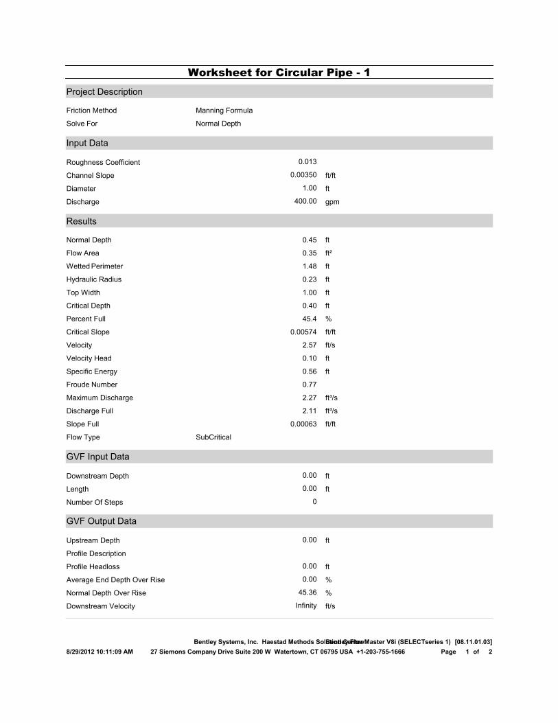
Project Description
Friction Method Manning Formula
Solve For Normal Depth
Input Data
Roughness Coefficient 0.013
Channel Slope 0.00350 ft/ft
Diameter 1.00 ft
Discharge 400.00 gpm
Results
Normal Depth 0.45 ft
Flow Area 0.35 ft²
Wetted Perimeter 1.48 ft
Hydraulic Radius 0.23 ft
Top Width 1.00 ft
Critical Depth 0.40 ft
Percent Full 45.4 %
Critical Slope 0.00574 ft/ft
Velocity 2.57 ft/s
Velocity Head 0.10 ft
Specific Energy 0.56 ft
Froude Number 0.77
Maximum Discharge 2.27 ft³/s
Discharge Full 2.11 ft³/s
Slope Full 0.00063 ft/ft
Flow Type SubCritical
GVF Input Data
Downstream Depth 0.00 ft
Length 0.00 ft
Number Of Steps 0
GVF Output Data
Upstream Depth 0.00 ft
Profile Description
Profile Headloss 0.00 ft
Average End Depth Over Rise 0.00 %
Normal Depth Over Rise 45.36 %
Downstream Velocity Infinity ft/s
Worksheet for Circular Pipe - 1
8/29/2012 10:11:09 AM
Bentley Systems, Inc. Haestad Methods Solution CenterBentley FlowMaster V8i (SELECTseries 1) [08.11.01.03]
27 Siemons Company Drive Suite 200 W Watertown, CT 06795 USA +1-203-755-1666 2of1Page

GVF Output Data
Upstream Velocity Infinity ft/s
Normal Depth 0.45 ft
Critical Depth 0.40 ft
Channel Slope 0.00350 ft/ft
Critical Slope 0.00574 ft/ft
Worksheet for Circular Pipe - 1
8/29/2012 10:11:09 AM
Bentley Systems, Inc. Haestad Methods Solution CenterBentley FlowMaster V8i (SELECTseries 1) [08.11.01.03]
27 Siemons Company Drive Suite 200 W Watertown, CT 06795 USA +1-203-755-1666 2of2Page