cover - steven engineeringstevenengineering.com/tech_support/pdfs/18mpc9440.pdf · • seven isa...
TRANSCRIPT
9440Industrial PC/ATTM
Rack Mount ComputerP/N 106501-001B
1997 XYCOM, INC.
Printed in the United States of America
XYCOM750 North Maple RoadSaline, Michigan 48176-1292(313) 429-4971
Xycom Revision Record
Address comments concerning thismanual to:
xycomTechnical Publications Department750 North Maple RoadSaline, Michigan 48176-1292
Revision Description Date
A Manual Released 6/96B Manual Updated (incorporates PCN 210) 7/97
Trademark InformationBrand or product names are registered trademarks of their respective owners.Windows is a registered trademark of Microsoft Corp. in the United States and other countries.
Copyright InformationThis document is copyrighted by Xycom Incorporated (Xycom) and shall not be reproduced or copied withoutexpressed written authorization from Xycom.
The information contained within this document is subject to change without notice. Xycom does notguarantee the accuracy of the information and makes no commitment toward keeping it up to date.

United States FCC Part 15, Subpart B, Class A EMICompliance StatementNote: This equipment has been tested and found to comply with limits fora Class A digital device, pursuant to part 15 of the FCC Rules. Theselimits are designed to provide reasonable protection against harmfulinterference when the equipment is operated in a commercialenvironment. This equipment generates, uses, and can radiate radiofrequency energy and, if not installed and used in accordance with theinstruction manual, may cause harmful interference to radiocommunications. Operation of this equipment in a residential area is likelyto cause harmful interference, in which case the user will be required tocorrect the interference at his own expense.
For Canadian UsersThis digital apparatus does not exceed the Class A limits for radio noiseemissions from digital apparatus as set out in the radio interferenceregulations of the Canadian Department of Communications.Le présent appareil numérique n’émet pas de bruits radioélectriquesdépassant les limites applicables aux appareils numériques des Class Aprescrites dans le Règlement sur le brouillage radioélectrique édicté par leministère des Communications du Canada.
For European Users - WARNINGThis is a Class A product. In a domestic environment this product maycause radio interference, in which case the user may be required to takeadequate measures.

WARNING for Electromagnetic CompatibilityThe connection of non-shielded equipment interface cables to thisequipment will invalidate FCC EMI and European Union EMCcompliance and may result in interference and/or susceptibility levelswhich are in violation of regulations which apply to the legal operation ofthis device. It is the responsibility of the system integrator and/or user toapply the following directions which relate to installation andconfiguration:
1. All interface cables must include braid/foil type shields.Communication cable connectors must be metal, ideally zinc die-cast backshell types, and provide 360 degree protection about theinterface wires. The cable shield braid must be terminateddirectly to the metal connector shell; ground drain wires alone arenot adequate.
2. EMC compliance is, in part, a function of PCB design. Thirdparty add-on PCB assemblies installed within this apparatus mayvoid EMC compliance. FCC/CE compliant PCB assembliesshould always be used where possible. Xycom can accept noresponsibility for the EMC performance of this system aftersystem integrator/user installation of PCB assemblies notmanufactured and/or expressly tested and approved forcompliance by Xycom. It is the responsibility of the systemintegrator/user to ensure that installation and operation of suchdevices does not void EMC compliance.
i
Table of Contents
Chapter 1 – Introduction
Product Overview .................................................................................................... 1-1About this Manual.................................................................................................... 1-1Standard Features .................................................................................................. 1-1Optional Features.................................................................................................... 1-2Unpacking the System............................................................................................. 1-2System Components................................................................................................ 1-2
Front Panel Components ...................................................................................... 1-3Rear Panel Components ....................................................................................... 1-5
Quick Start-Up ......................................................................................................... 1-6Regulatory Compliance ........................................................................................... 1-7
Agency Approvals ................................................................................................. 1-7Regulatory Compliance ......................................................................................... 1-7
Chapter 2 – Testing the 9440 ........................................................................................ 2-1
Diagnostic Tests ...................................................................................................... 2-1Preparing for the Tests............................................................................................ 2-1Running the Tests ................................................................................................... 2-2
Chapter 3 – Installation ................................................................................................ 3-1
Introduction.............................................................................................................. 3-1General Configuration........................................................................................... 3-1
Installing Cards and Devices ................................................................................... 3-3Opening the Case ................................................................................................. 3-3Installing a Processor Card ................................................................................... 3-4Installing Other Cards ........................................................................................... 3-4
Installing Drives ....................................................................................................... 3-5Preparing the System for Use.................................................................................. 3-7Installing the System into A Rack............................................................................. 3-7Mounting Considerations ......................................................................................... 3-7System Power.......................................................................................................... 3-8Electrical Noise ........................................................................................................ 3-8Excessive Line Voltage............................................................................................ 3-9Rack-mounting and Installing the 9440.................................................................. 3-10
Slide Rail Mounting ............................................................................................. 3-10Rack Mounting .................................................................................................... 3-11
Connecting External Hardware Options ................................................................. 3-12Keyboards........................................................................................................... 3-12Serial Mouse ....................................................................................................... 3-12
Installing Operating Systems ................................................................................. 3-13Derating the Power Supply .................................................................................... 3-13
Chapter 4 – Maintenance ............................................................................................. 4-1
Preventive Maintenance .......................................................................................... 4-1Care of the 9440 Cabinet...................................................................................... 4-1Changing the Fan Filter ........................................................................................ 4-2

9440 Industrial Rack Mount PC/AT Computer
ii
Chapter 5 – Product Repair.......................................................................................... 5-1
Spare Parts List ....................................................................................................... 5-1Product Repair ........................................................................................................ 5-2
Preparing the Unit for Shipment ............................................................................ 5-2
Appendix A – Specifications
Appendix B – Pinouts

i
1-1
Chapter 1 – Introduction
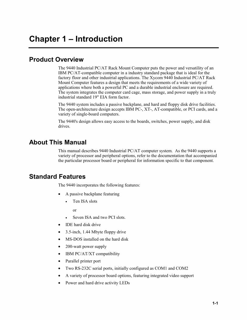
Product OverviewThe 9440 Industrial PC/AT Rack Mount Computer puts the power and versatility of anIBM PC/AT-compatible computer in a industry standard package that is ideal for thefactory floor and other industrial applications. The Xycom 9440 Industrial PC/AT RackMount Computer features a design that meets the requirements of a wide variety ofapplications where both a powerful PC and a durable industrial enclosure are required.The system integrates the computer card cage, mass storage, and power supply in a trulyindustrial standard 19" EIA form factor.The 9440 system includes a passive backplane, and hard and floppy disk drive facilities.The open-architecture design accepts IBM PC-, XT-, AT-compatible, or PCI cards, and avariety of single-board computers.The 9440's design allows easy access to the boards, switches, power supply, and diskdrives.
About This ManualThis manual describes 9440 Industrial PC/AT computer system. As the 9440 supports avariety of processor and peripheral options, refer to the documentation that accompaniedthe particular processor board or peripheral for information specific to that component.
Standard FeaturesThe 9440 incorporates the following features:
• A passive backplane featuring• Ten ISA slots
or• Seven ISA and two PCI slots.
• IDE hard disk drive• 3.5-inch, 1.44 Mbyte floppy drive• MS-DOS installed on the hard disk• 200-watt power supply• IBM PC/AT/XT compatibility• Parallel printer port• Two RS-232C serial ports, initially configured as COM1 and COM2• A variety of processor board options, featuring integrated video support• Power and hard drive activity LEDs
9440 Industrial PC/AT Rack Mount Computer
1-2
Optional FeaturesOptional items available for use with the 9440 include:
• Larger-capacity hard drives• Solid state drive options• CD-ROM capability• 9440-RMS rack-mounting slide rail kit
Unpacking The SystemAfter removing the 9440 from its box, verify that you have the parts listed below. Savethe box and inner wrapping in case you need to reship the unit.If you ordered the system with a CD-ROM installed, you will receive a CD-ROM driverdisk.
• 9440 unit• Documentation kit, which includes:
• Power cable• Test software diskette• Two front door lock keys• 9440 user manual• CPU Manual• Business reply card
System ComponentsThis section describes the external components of the 9440.
Chapter 1 – Introduction
1-3
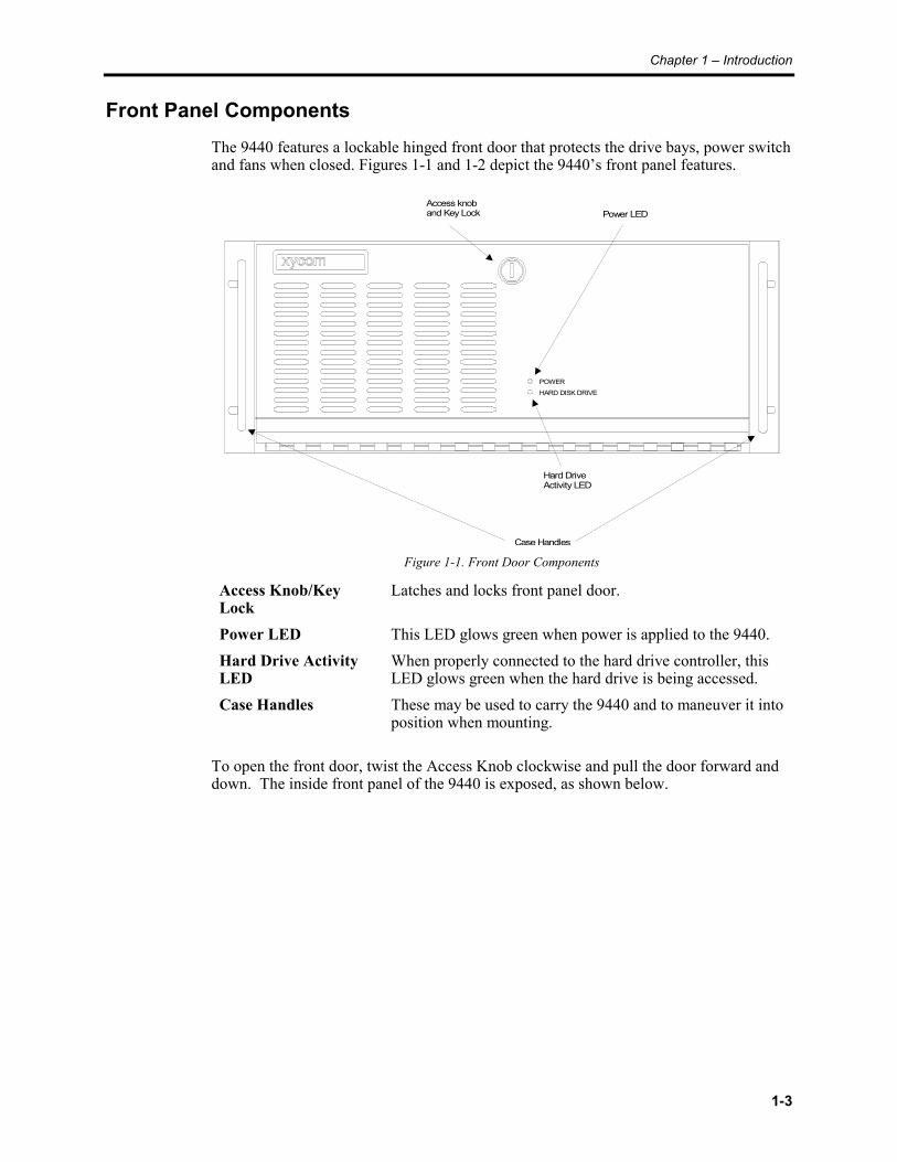
Front Panel ComponentsThe 9440 features a lockable hinged front door that protects the drive bays, power switchand fans when closed. Figures 1-1 and 1-2 depict the 9440’s front panel features.
POWER
HARD DISK DRIVE
Access knoband Key Lock Power LED
Hard DriveActivity LED
Case Handles
Figure 1-1. Front Door Components
Access Knob/KeyLock
Latches and locks front panel door.
Power LED This LED glows green when power is applied to the 9440.Hard Drive ActivityLED
When properly connected to the hard drive controller, thisLED glows green when the hard drive is being accessed.
Case Handles These may be used to carry the 9440 and to maneuver it intoposition when mounting.
To open the front door, twist the Access Knob clockwise and pull the door forward anddown. The inside front panel of the 9440 is exposed, as shown below.
9440 Industrial PC/AT Rack Mount Computer
1-4
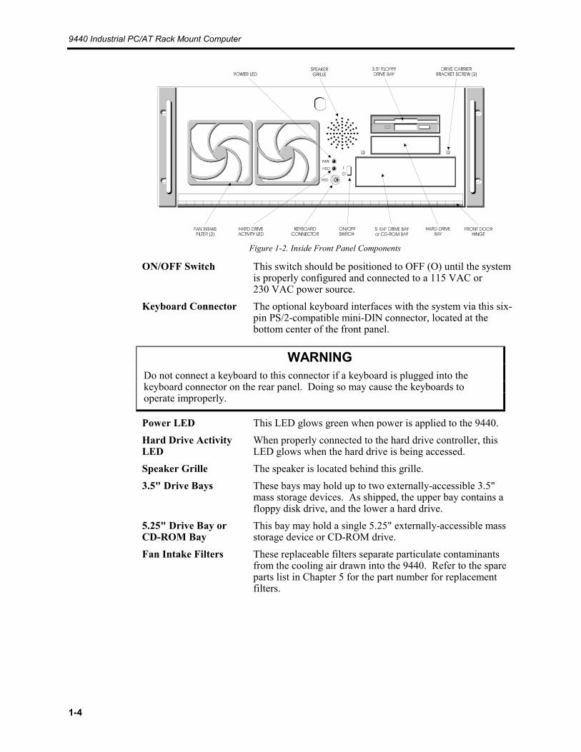
Figure 1-2. Inside Front Panel Components
ON/OFF Switch This switch should be positioned to OFF (O) until the systemis properly configured and connected to a 115 VAC or230 VAC power source.
Keyboard Connector The optional keyboard interfaces with the system via this six-pin PS/2-compatible mini-DIN connector, located at thebottom center of the front panel.
WARNINGDo not connect a keyboard to this connector if a keyboard is plugged into thekeyboard connector on the rear panel. Doing so may cause the keyboards tooperate improperly.
Power LED This LED glows green when power is applied to the 9440.Hard Drive ActivityLED
When properly connected to the hard drive controller, thisLED glows when the hard drive is being accessed.
Speaker Grille The speaker is located behind this grille.3.5" Drive Bays These bays may hold up to two externally-accessible 3.5"
mass storage devices. As shipped, the upper bay contains afloppy disk drive, and the lower a hard drive.
5.25" Drive Bay orCD-ROM Bay
This bay may hold a single 5.25" externally-accessible massstorage device or CD-ROM drive.
Fan Intake Filters These replaceable filters separate particulate contaminantsfrom the cooling air drawn into the 9440. Refer to the spareparts list in Chapter 5 for the part number for replacementfilters.
Chapter 1 – Introduction
1-5
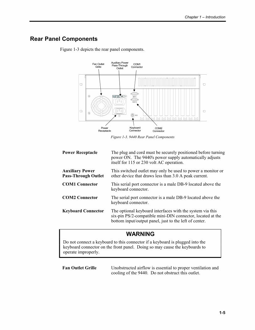
Rear Panel ComponentsFigure 1-3 depicts the rear panel components.
Fan OutletGrille
PowerReceptacle
COM1Connector
COM2Connector
KeyboardConnector
Auxillary PowerPass-Through
Outlet
Figure 1-3. 9440 Rear Panel Components
Power Receptacle The plug and cord must be securely positioned before turningpower ON. The 9440's power supply automatically adjustsitself for 115 or 230 volt AC operation.
Auxiliary PowerPass-Through Outlet
This switched outlet may only be used to power a monitor orother device that draws less than 3.0 A peak current.
COM1 Connector This serial port connector is a male DB-9 located above thekeyboard connector.
COM2 Connector The serial port connector is a male DB-9 located above thekeyboard connector.
Keyboard Connector The optional keyboard interfaces with the system via thissix-pin PS/2-compatible mini-DIN connector, located at thebottom input/output panel, just to the left of center.
WARNINGDo not connect a keyboard to this connector if a keyboard is plugged into thekeyboard connector on the front panel. Doing so may cause the keyboards tooperate improperly.
Fan Outlet Grille Unobstructed airflow is essential to proper ventilation andcooling of the 9440. Do not obstruct this outlet.
9440 Industrial PC/AT Rack Mount Computer
1-6
NOTEThe pinouts for connectors and ports are shown in Appendix B.
Quick Start-Up
NOTEAt minimum, you should read this section and the appendices. This section getsyour system running without explaining options or capabilities of the system. Theappendices provide pinouts, error messages, setup information, specifications, etc.
To prepare the system for use, perform the steps listed below:
WARNINGTurn the power to the unit off and unplug the power cord while making anyadjustments to the inside or outside of the unit.
1. Connect the video cable from a VGA video monitor to the CRT video connector onthe CPU/video card.
2. Attach optional keyboard and/or mouse.• Connect an external full-stroke keyboard to the keyboard connector on either the
front or the rear panel.
WARNINGDo not connect more than one keyboard to the unit at a time.
• A serial mouse may be connected to one of the serial ports on the rear of theunit.
3. Attach other optional equipment.4. Attach the power cord from the power receptacle to a properly grounded 115 or
230 VAC outlet.5. Turn on power to the unit. The system will boot up to the C:> prompt.6. Install application software from the A: floppy disk drive.7. Perform the test procedure described in Chapter 2 before rack-mounting or otherwise
installing the 9440.

Chapter 1 – Introduction
1-7
Regulatory ComplianceThe Xycom 9440 Industrial PC/AT Computer is UL and CUL listed and has also beeninvestigated for compliance with the following standards:
Agency Approvals
• UL UL 1950 (Information Technology Equipment) EN 60950 (Information Technology Equipment)• CUL CSA 22.2, #950 (Information Technology Equipment)
Regulatory Compliance• EU "CE Marking" EMI EN 55022, Class A Immunity EN 50082-2 Safety EN 60950• FCC 47 CFR, Part 15, Class A•

2-1
Chapter 2 - Testing the 9440
Diagnostic TestsDiagnostic tests are provided as a tool to verify the operation of the 9440 systemhardware functions. If any of these tests fail, either you do not have the correct defaultsetting or there is a failure. Check the default settings and run the tests again. If thefailure occurs again, contact Xycom’s Product Repair & Customization Department, asdescribed in Product Repair, in Chapter 5 of this manual.
NOTEUnexpected failures may occur if Xycom diagnostics are run with device drivers ormemory resident programs installed on the system. Remove these before running anydiagnostic tests.
Make sure the Setup Menu is configured properly (factory set configuration). If your9440 is configured with an AT4+ processor card, to enter the Setup Menu, press[Ctrl+Alt+S] simultaneously after the POST RAM test has completed. Make thenecessary changes by following directions on the screen. Press [F10] to save the Setupand [Esc] to exit. Refer to your CPU manual for more information on the Setup Menu.If your 9440 is configured with an AT5+ processor card, to enter the Setup Menu, press[F2] after the POST RAM test has completed. Make the necessary changes by followingdirections on the screen. Press [F10] to save the Setup and [Esc] to exit. Refer to yourCPU manual for more information on the Setup Menu.To test your system, you need the following equipment:
• Xycom System Test Disk—3.5-inch, DS/DD disk (bootable), part number 99290-001• IBM PC/AT-compatible keyboard (Xycom part number 91971-001 or equivalent)• Centronics-compatible printer cable• Parallel printer (Centronics-style interface)• Two serial loopback test connectors (refer to Figure 2-1 for pinouts)• Scratch disk—formatted 3.5-inch, DS/HD (1.44 Mbyte)
Preparing For The TestsPerform the following steps before beginning the system tests:
1. Place the CPU board jumpers and switches to the factory-set positions. Refer to yourCPU manual for these settings.
2. Plug the female end of the AC power cable into the rear of the unit and the male endinto a properly grounded outlet.
9440 Industrial PC/AT Rack Mount Computer
2-2
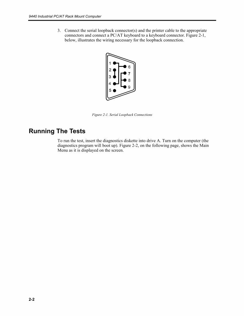
3. Connect the serial loopback connector(s) and the printer cable to the appropriateconnectors and connect a PC/AT keyboard to a keyboard connector. Figure 2-1,below, illustrates the wiring necessary for the loopback connection.
Figure 2-1. Serial Loopback Connections
Running The TestsTo run the test, insert the diagnostics diskette into drive A. Turn on the computer (thediagnostics program will boot up). Figure 2-2, on the following page, shows the MainMenu as it is displayed on the screen.
Chapter 2 – Testing the 9440
2-3
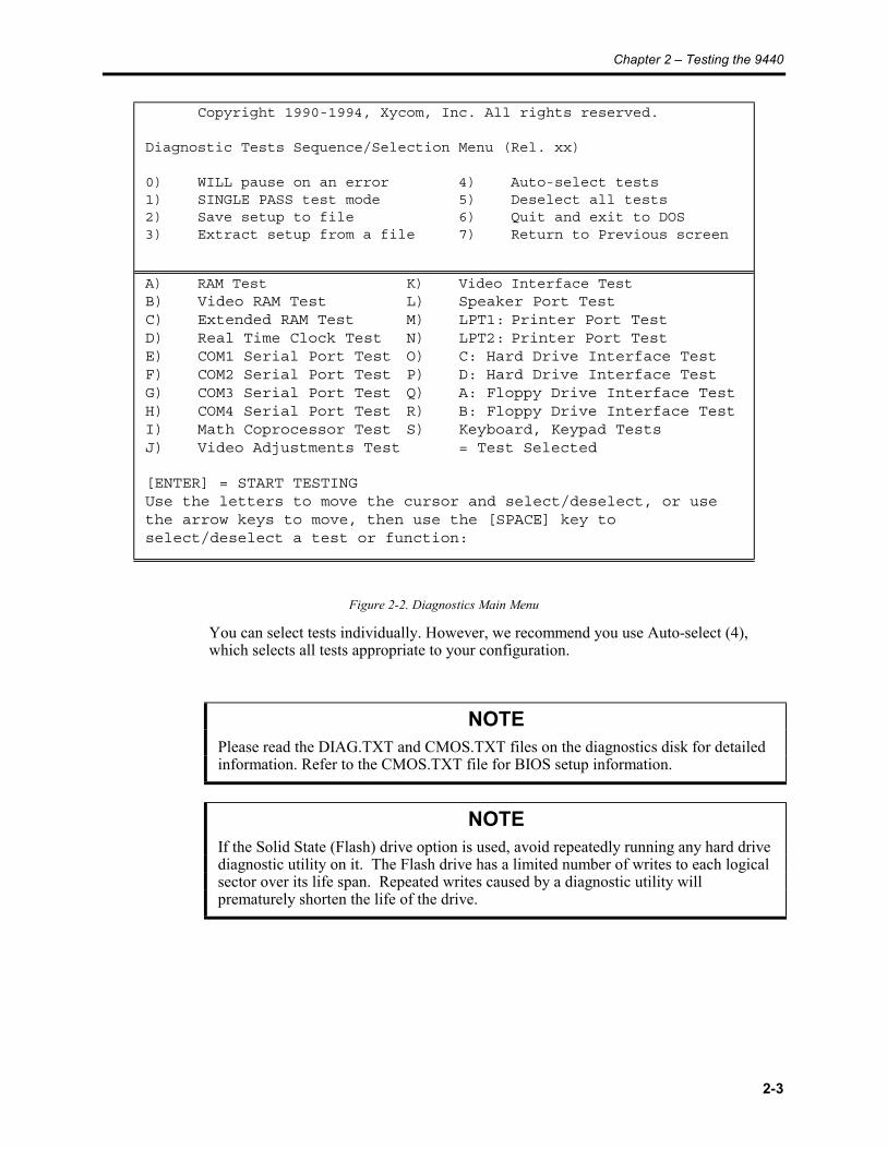
Copyright 1990-1994, Xycom, Inc. All rights reserved.
Diagnostic Tests Sequence/Selection Menu (Rel. xx)
0) WILL pause on an error 4) Auto-select tests1) SINGLE PASS test mode 5) Deselect all tests2) Save setup to file 6) Quit and exit to DOS3) Extract setup from a file 7) Return to Previous screen
A) RAM Test K) Video Interface TestB) Video RAM Test L) Speaker Port TestC) Extended RAM Test M) LPT1: Printer Port TestD) Real Time Clock Test N) LPT2: Printer Port TestE) COM1 Serial Port Test O) C: Hard Drive Interface TestF) COM2 Serial Port Test P) D: Hard Drive Interface TestG) COM3 Serial Port Test Q) A: Floppy Drive Interface TestH) COM4 Serial Port Test R) B: Floppy Drive Interface TestI) Math Coprocessor Test S) Keyboard, Keypad TestsJ) Video Adjustments Test = Test Selected
[ENTER] = START TESTINGUse the letters to move the cursor and select/deselect, or usethe arrow keys to move, then use the [SPACE] key toselect/deselect a test or function:
Figure 2-2. Diagnostics Main Menu
You can select tests individually. However, we recommend you use Auto-select (4),which selects all tests appropriate to your configuration.
NOTEPlease read the DIAG.TXT and CMOS.TXT files on the diagnostics disk for detailedinformation. Refer to the CMOS.TXT file for BIOS setup information.
NOTEIf the Solid State (Flash) drive option is used, avoid repeatedly running any hard drivediagnostic utility on it. The Flash drive has a limited number of writes to each logicalsector over its life span. Repeated writes caused by a diagnostic utility willprematurely shorten the life of the drive.
3-1
Chapter 3 – Installation
IntroductionThis chapter describes how to install options into the 9440, and how to mount it into a rack.
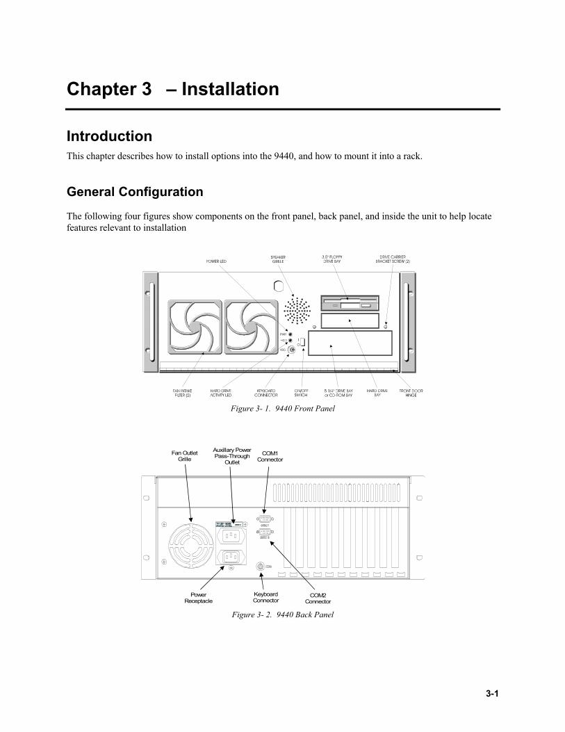
General Configuration
The following four figures show components on the front panel, back panel, and inside the unit to help locatefeatures relevant to installation
Figure 3- 1. 9440 Front Panel
Fan OutletGrille
PowerReceptacle
COM1Connector
COM2Connector
KeyboardConnector
Auxillary PowerPass-Through
Outlet
Figure 3- 2. 9440 Back Panel
9440 Industrial PC/AT Rack Mount Computer
3-2
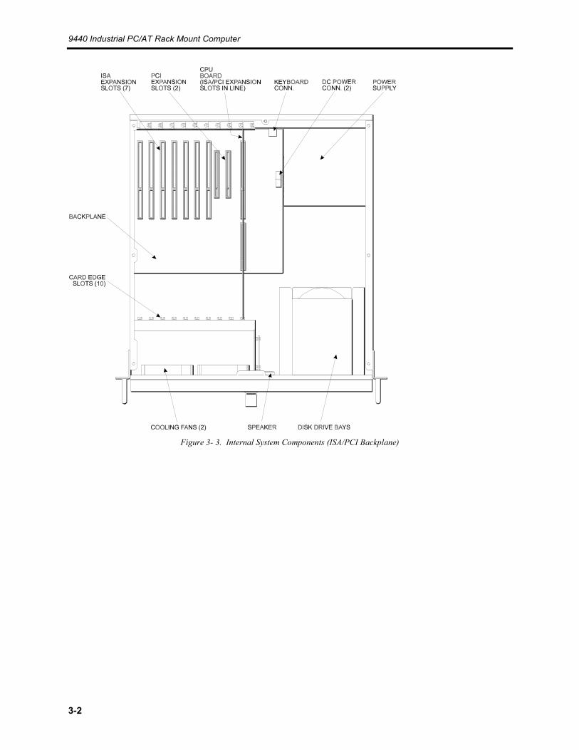
Figure 3- 3. Internal System Components (ISA/PCI Backplane)
Chapter 3 – Installation
3-3
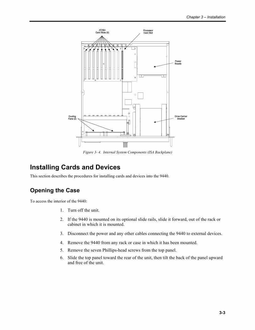
Figure 3- 4. Internal System Components (ISA Backplane)
Installing Cards and DevicesThis section describes the procedures for installing cards and devices into the 9440.
Opening the CaseTo access the interior of the 9440:
1. Turn off the unit.
2. If the 9440 is mounted on its optional slide rails, slide it forward, out of the rack orcabinet in which it is mounted.
3. Disconnect the power and any other cables connecting the 9440 to external devices.
4. Remove the 9440 from any rack or case in which it has been mounted.5. Remove the seven Phillips-head screws from the top panel.6. Slide the top panel toward the rear of the unit, then tilt the back of the panel upward
and free of the unit.
9440 Industrial PC/AT Rack Mount Computer
3-4
Installing a Processor CardTo install a processor card:
1. Open the case, as described above.2. Remove the blank ORB from the slot nearest the power supply. Save the screw.3. Connect the ribbon cables from the backplane board to the processor card. Pay
special attention to the orientation of the plugs as you connect them to the headers onthe processor card. The stripe on the cable corresponds to pin 1 on the header on theprocessor card.
4. Slide the processor card into the slot. Push down on the card evenly until it firmlyseats in the card cage connectors.
NOTEDO NOT force the board or apply uneven pressure.
5. Secure the processor card ORB to the 9440 by replacing and tightening the screwthat was removed in Step 2.
6. Slide the top panel into position, then replace and tighten the seven screws.7. Reconnect the I/O cables you disconnected when opening the unit.8. Reconnect the power cables you disconnected when opening the unit.9. If the unit is mounted on its optional slide rails, slide the unit back into the rack or
cabinet in which it is mounted.
Installing Other CardsTo install a card into the 9440 unit:
1. Check that the memory, I/O configuration and processor requirements of the boardyou want to install do not conflict with the CPU and memory maps of boards alreadyinstalled in your system.
2. Check that the additional power required by the card will not cause the 9440 toexceed its current ratings. See Derating the Power Supply, later in this chapter forcurrent ratings and specifications.
3. Open the case, as described above.4. Remove the ORB cover for the slot that the card will occupy. Save the screw.
NoteWhen installing cards into system equipped with the combination ISA/PCI backplane, youmay install an ISA card in the shared ISA/PCI slot or a PCI card in the PCI slot immediatelyadjacent to it. Due to physical clearance limitations, you may NOT install an ISA card in theshared ISA/PCI slot and a PCI card in the adjacent PCI slot.

Chapter 3 – Installation
3-5
5. Slide the card into the slot. Push down on the card evenly until it firmly seats in thecard cage connectors.
NoteDO NOT force the board or apply uneven pressure.
6. Secure the card's ORB to the 9440 by replacing and tightening the screw that wasremoved in Step 4
7. Slide the top panel into position, then replace and tighten the seven screws.8. Reconnect the I/O cables you disconnected when opening the unit.9. Reconnect the power cables you disconnected when opening the unit.10. If the unit is mounted on its optional slide rails, slide the unit back into the rack or
cabinet in which it is mounted.
Installing DrivesTo install hard drives or other mass storage devices into the 9440 unit:
1. Check that the memory, I/O configuration and processor requirements of the driveyou want to install do not conflict with the CPU and memory maps of boards alreadyinstalled in your system. If you must install an additional controller card, verify thatits requirements do not conflict, either.
2. Check that the additional power required by the device will not cause the 9440 toexceed its current ratings. See Derating the Power Supply, later in this chapter forcurrent ratings and specifications.
3. Open the case, as described above.4. Open the front door and remove the two Phillips-head drive carrier bracket screws
located on either side of the lower 3.5" drive bay, as shown in Figure 3-1, above.Save these screws.
5. Slide the drive carrier bracket toward the rear of the unit. then lift it straight up andout of the case, as far as the cables attached to the drives will permit.

9440 Industrial PC/AT Rack Mount Computer
3-6
3.5" DriveBays (2)
5.25" DriveBay (1)
Figure 3- 5. The Drive Carrier Bracket
6. Disconnect the power and ribbon cables connected to any drives already mounted inthe drive carrier bracket, then place the drive carrier bracket on a solid, level worksurface.
7. If you are installing a removable-media device, remove the two Philips-head screwsthat hold the blank bezel plate to the bracket, then remove the bezel plate.
5.25" Device(not included)
3.5" HardDrive
3.5" FloppyDrive
5.25" BayBlank Bezel
Mounting Screws(4 per device installed)
Bezel Mounting Screws(2 per blank bezel installed)
Figure 3- 6. The Drive Carrier Bracket (Exploded View)

Chapter 3 – Installation
3-7
8. Slide the device into the bracket, from the rear, until the drive's mounting holes lineup with the corresponding holes in the mounting bracket, then install the mountingscrews, two on each side. Slide-mounting rails are not used when mounting drivesinto the drive carrier bracket.
9. Connect the power cable and ribbon cable(s) to the new drive, then reconnect thecables to any devices that were already installed in the drive carrier bracket.
10. Install any controller card required by the new drive, as described above.11. Set the drive carrier bracket back into the case, then slide it forward in the case, until it rests
against the front panel. Make sure that the bracket is properly engaged beneath the tabs on thefloor of the case. Re-install the two Philips-head screws you removed in Step 4.
12. Slide the top panel into position, then replace and tighten the seven screws.
13. Reconnect the I/O cables you disconnected when opening the unit.14. Reconnect the power cables you disconnected when opening the unit.15. If the unit is mounted on its optional slide rails, slide the unit back into the rack or cabinet in
which it is mounted.
Preparing The System For UseTo prepare the system for use, perform the steps listed below. If you have purchased any options, install themaccording to the instructions in the next sections.
1. Attach the power cord by connecting one end to the power receptacle on the rear ofthe 9440 (see Figure 3-2) and the other to a properly grounded 115 or 230 VACoutlet.
2. Connect the video cable from the 9440 to the video connector on a compatiblemonitor.
3. Connect the keyboard cable from your external keyboard to the keyboard connectoron either the front or back panel of the 9440.
Installing The System Into A RackThe 9440’s rugged design allows it to be installed in most industrial environments. The unit is intended to bemounted in an enclosure that protects against contaminants such as moisture, dust, and other particulate matter, suchas a Type 12 enclosure. Metal enclosures also help minimize the effects of electromagnetic radiation that may begenerated by nearby equipment.
Mounting ConsiderationsFollow these guidelines when installing your 9440:
• Select an enclosure and place the unit to allow easy access to the ports.• Account for the unit’s depth as well as cabling when choosing the depth of the
enclosure.• Mount the unit in an upright position.• When installing the unit in a rack, take care to install it in such a way as to ensure
that it does not cause a hazard from uneven mechanical loading.

9440 Industrial PC/AT Rack Mount Computer
3-8
• Place the unit at a comfortable working level.• Consider locations of accessories such as AC power outlets and lighting (interior
lighting and windows) for installation and maintenance convenience.• Condensation should be prevented by installing a thermostat-controlled heater or air
conditioner, if needed.• To allow for maximum cooling, avoid obstructing the air flow.• Place fans or blowers close to the heat generating devices. If using a fan, make sure
that outside air is not brought inside the enclosure unless a fabric or other reliablefilter is used. This filtration prevents conductive particles or other harmfulcontaminants from entering the enclosure.
• Do not select a location near equipment that generates excessive electromagneticinterference (EMI) or radio frequency interference (RFI) (equipment such as highpower welding machines, induction heating equipment, and large motor starters).
• Place incoming power line devices (such as isolation or constant voltagetransformers, local power disconnects, and surge suppressors) away from the unit.The proper location of incoming line devices keeps power wire runs as short aspossible and minimizes electrical noise transmitted to the unit.
• Make sure the location does not exceed the unit’s shock, vibration, and temperaturespecifications.
• The 9440 is rated at 115/230 VAC at 6.3 Amps, maximum. Circuit overloading ofthe supply circuit must be avoided.
System PowerIt is always a good practice is to use isolation transformers on the incoming AC power line to the unit. An isolationtransformer is especially desirable in cases in which heavy equipment is likely to introduce noise onto the AC line.The isolation transformer can also serve as a step-down transformer to reduce the incoming line voltage to a desiredlevel. The transformer should have a sufficient power rating (units of volt-amperes) to supply the load adequately.
The following practices should be observed:
• Separate ground wires from power wires at the point of entry to the enclosure. Tominimize the ground wire length within the enclosure, locate the ground referencepoint near the point of entry for the plant power supply.
• The safety ground should be connected to earth ground.
Electrical NoiseDigital technology and low power analog circuits are sensitive to electrical noise. Within the industrial environmentelectrical noise is commonplace. Some examples of noise generating sources are high frequency mini-arcs betweenswitch contacts at transition time (relays, etc.), transients from highly inductive loads when abruptly shut off(motors, etc.), and RF power (hand-held radio transceivers). Noise can find paths into sensitive circuits viaconducted, capacitive, or inductive coupling. When this occurs malfunctions are likely to result which usuallyappear random in nature.
Xycom products are engineered to maintain a high level of immunity to electrical noise through the use of filters,shielding, and careful grounding techniques. However, several factors regarding system installation must be givencareful consideration by system integrators and/or installation personnel. Note the Electromagnetic compatibilitywarning located at the beginning of this manual.
Capacitive coupling into cables will be minimized with the use of shielded cables. Cables which incorporate bothcopper braid and foil shields are preferred. Metal I/O cable backshell connectors should be used rather than plain or
Chapter 3 – Installation
3-9
conductive plastic. Cable shields should be terminated directly to the metal backshell. The copper braid shield isideal for this termination. Shield drain wires alone are inferior.
Inductive coupling is best prevented through separation of conductors. I/O and signal cables should not be routed inparallel and within close proximity to AC mains conductors or other high voltage/current wiring.
As noted elsewhere within this manual, proper grounding of this equipment is essential. Noise immunity techniquesemployed within this design cannot be optimized otherwise. The traditional “ground bus” widely used withinindustry is being replaced with a “star” grounding technique. In an enclosure or rack, each apparatus whichincorporates sensitive electronic technology should have its own low impedance protective earth conductor. Theseconductors should subsequently be terminated at one common point within the rack/enclosure (hence the term“star”). This single-point ground should then be connected to facility (mains) ground in typical installations. Inthose cases where noise generating sources are extreme, this single-point ground should be routed to a close earthgrounding rod or appropriate section of building structure. Protective earth grounding conductors attached to noisegenerating devices such as motors should not share the same conductor or point of termination. Points oftermination should be at least 10 feet (3 meters) apart.
Be sure to reference all relevant national, state/provincial, and local electric codes with respect to legal wiringpractice.
Excessive Line VoltageThe power supply section of the 9440 is built to operate at voltages from 100 to 120 VAC or from 200 to 240 VACand still allow the system to function within its operating margin. As long as the incoming voltage is adequate, thepower supply provides all of the logic voltages necessary to support the processor, memory, and I/O.
In cases in which the installation is subject to unusual AC line variations, a constant voltage transformer can be usedto prevent the system from shutting down too often. However, a first step toward the solution of the line variations isto correct any possible feed problem in the distribution system. If this correction does not solve the problem, aconstant voltage transformer must be used.
The constant voltage transformer stabilizes the input voltage to the unit by compensating for voltage changes at theprimary in order to maintain a steady voltage at the secondary. When using a constant voltage transformer, check thatthe power rating is sufficient to supply the unit.
Rack-mounting and Installing the 9440To install the 9440 in a standard EIA 19" rack, follow the steps described in the applicable section below.
Slide Rail Mounting
1. Disconnect all cables and cords from the 9440 unit.2. Place the 9440 unit on a solid work surface.
3. Attach the slide rails from the 9440-RMS slide rail kit to the 9440 unit, using the#8-32 screws provided with the kit. This is illustrated in Figure 3-7, below.

9440 Industrial PC/AT Rack Mount Computer
3-10
Rail MountingScrews (8)
Slide Rails(Extended)
Figure 3- 7. Installing the Optional Slide Rails
Chapter 3 – Installation
3-11
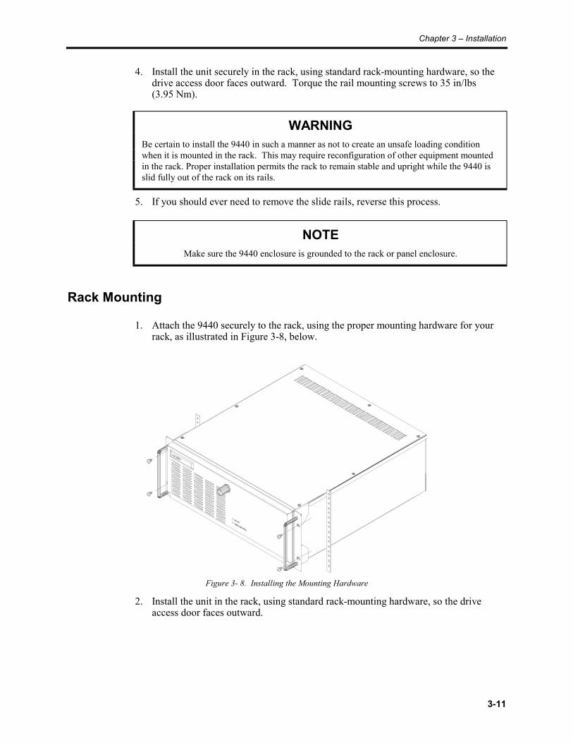
4. Install the unit securely in the rack, using standard rack-mounting hardware, so thedrive access door faces outward. Torque the rail mounting screws to 35 in/lbs(3.95 Nm).
WARNINGBe certain to install the 9440 in such a manner as not to create an unsafe loading conditionwhen it is mounted in the rack. This may require reconfiguration of other equipment mountedin the rack. Proper installation permits the rack to remain stable and upright while the 9440 isslid fully out of the rack on its rails.
5. If you should ever need to remove the slide rails, reverse this process.
NOTEMake sure the 9440 enclosure is grounded to the rack or panel enclosure.
Rack Mounting
1. Attach the 9440 securely to the rack, using the proper mounting hardware for yourrack, as illustrated in Figure 3-8, below.
Figure 3- 8. Installing the Mounting Hardware
2. Install the unit in the rack, using standard rack-mounting hardware, so the driveaccess door faces outward.
9440 Industrial PC/AT Rack Mount Computer
3-12
WARNINGBe certain to install the 9440 in such a manner as not to create an unsafe loading conditionwhen it is mounted in the rack. This may require reconfiguration of other equipment mountedin the rack.
3. To remove the 9440 from the rack, reverse the process.
NOTEMake sure the 9440 enclosure is grounded to the rack or panel enclosure.
Connecting External Hardware OptionsThis section explains how to connect the external hardware options available with the 9440.
KeyboardsThe 9440 can be connected to any standard PS/2-compatible keyboard, using either the front keyboard port or therear. An AT-compatible keyboard may be connected by using an AT-PS/2 adapter plug or adapter cable between thekeyboard and the 9440's keyboard port.
WARNINGDo not connect keyboards to both the front and the rear keyboard ports at the same time.Doing so may cause the keyboards to operate improperly.
Serial MouseTo install Xycom’s 4100-MS1 three-button serial mouse, attach the connector on the mouse cable to one of the serialport connectors (COM1 or COM2) on the input/output panel of the 9440. For further instructions, refer to themanual that accompanied the mouse.
Chapter 3 – Installation
3-13
Installing Operating SystemsIf you want to install a new operating system or re-install a current operating system, refer to the operating system’smanual for instructions.
NoteIf you had Windows NT preloaded on your system and do not have a CD-ROM drive installed,you may have to purchase and install standard or parallel port CD-ROM drive in order toreinstall Windows NT. This is because Windows NT operating system only ships on CD-ROM.
CautionUse of controls adjustments or the performance of procedures other than those specified hereinmay result in hazardous radiation exposure.
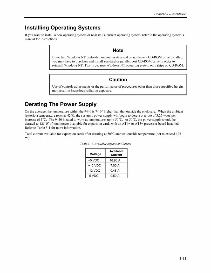
Derating The Power SupplyOn the average, the temperature within the 9440 is 7-10° higher than that outside the enclosure. When the ambient(exterior) temperature reaches 42°C, the system’s power supply will begin to derate at a rate of 3.25 watts perincrease of 1°C. The 9440 is rated to work at temperatures up to 50°C. At 50°C, the power supply should bederated to 125 W of total power available for expansion cards with an AT4+ or AT5+ processor board installed.Refer to Table 3-1 for more information.
Total current available for expansion cards after derating at 50°C ambient outside temperature (not to exceed 125W):
Table 3- 1. Available Expansion Current
VoltageAvailableCurrent
+5 VDC 16.90 A +12 VDC 7.00 A -12 VDC 0.48 A -5 VDC 0.50 A
4-1
Chapter 4 – Maintenance
Preventive MaintenanceThe 9440 was designed to withstand the harsh environment of the factory floor. Routinemaintenance can help keep your 9440 in good operating condition. Preventivemaintenance consists of several basic procedures and checks that will greatly reduce thechances of system malfunction. Preventive maintenance should be scheduled along withthe regular equipment maintenance to minimize 9440 down time.Some preventive measures are listed below.
• Clean or change the fan filters periodically to ensure that the air circulating in theunit is clean. Filter maintenance should not be put off until the scheduledmaintenance, but should be performed periodically, depending on the amount of dustin the area.
• Remove dust and dirt from PC components. If dust builds up on heat sinks andcircuitry, the resulting reduction in heat dissipation could cause the unit tomalfunction. If dust reaches the electronic boards, a short circuit could occur.
• Check the connections to I/O modules, especially in environments where shockcould loosen the connections. Check to see that all plugs, sockets, terminal strips,and module connections are solid.
• Do not move noise generating equipment too near the 9440.• Stock spare parts to minimize down time resulting from part failure. The spare parts
stocked should be 10 percent of the number of each unit used. There should be onespare CPU card each, regardless of the number of CPUs used. Each power supplyshould have a back-up. In certain applications where immediate operation of a failedsystem is required, an entire spare unit may need to be stocked. See the spare partslist in Table 5-1.
• When replacing a module, make sure it is the correct type. If the new module solvesthe problem, but the failure reoccurs after a while, check for inductive loads that maybe generating voltage and current spikes that may require external suppression.
Care of the 9440 Cabinet
CAUTIONNever clean the 9440 while power is on. Disconnect the monitor power cord beforecleaning. Avoid spraying liquids into the ventilation slots.
To clean the exterior of the 9440, dampen a soft cloth with a mild cleaning solution, suchas dishwashing detergent. After cleaning, rinse cloth thoroughly, wring dry, then wipecleaned surfaces to remove any residual detergent.
9440 Industrial PC/AT Rack Mount Computer
4-2
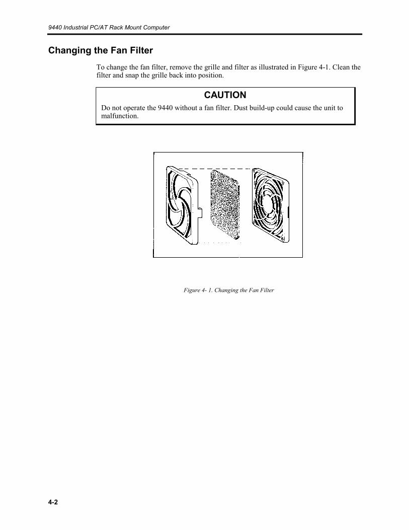
Changing the Fan FilterTo change the fan filter, remove the grille and filter as illustrated in Figure 4-1. Clean thefilter and snap the grille back into position.
CAUTIONDo not operate the 9440 without a fan filter. Dust build-up could cause the unit tomalfunction.
Figure 4- 1. Changing the Fan Filter
5-1
Chapter 5 – Product Repair
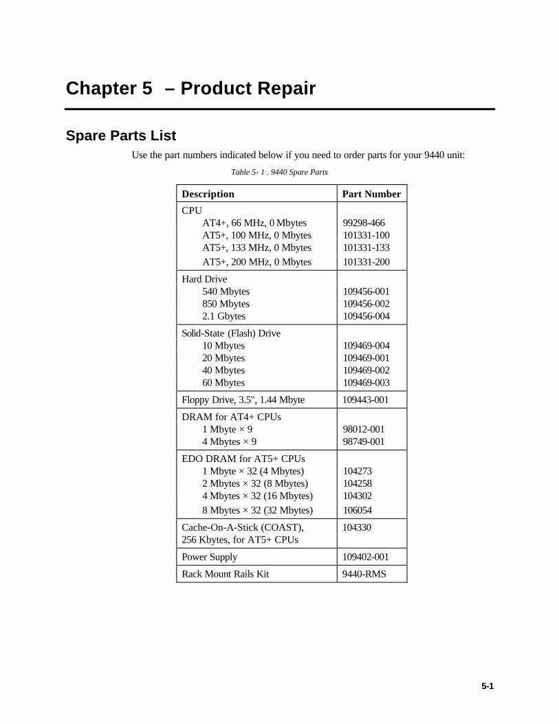
Spare Parts ListUse the part numbers indicated below if you need to order parts for your 9440 unit:
Table 5- 1 . 9440 Spare Parts
Description Part Number
CPUAT4+, 66 MHz, 0 Mbytes 99298-466AT5+, 100 MHz, 0 Mbytes 101331-100AT5+, 133 MHz, 0 Mbytes 101331-133AT5+, 200 MHz, 0 Mbytes 101331-200
Hard Drive540 Mbytes 109456-001850 Mbytes 109456-0022.1 Gbytes 109456-004
Solid-State (Flash) Drive10 Mbytes 109469-00420 Mbytes 109469-00140 Mbytes 109469-00260 Mbytes 109469-003
Floppy Drive, 3.5", 1.44 Mbyte 109443-001
DRAM for AT4+ CPUs1 Mbyte × 9 98012-0014 Mbytes × 9 98749-001
EDO DRAM for AT5+ CPUs1 Mbyte × 32 (4 Mbytes) 1042732 Mbytes × 32 (8 Mbytes) 1042584 Mbytes × 32 (16 Mbytes) 1043028 Mbytes × 32 (32 Mbytes) 106054
Cache-On-A-Stick (COAST),256 Kbytes, for AT5+ CPUs
104330
Power Supply 109402-001
Rack Mount Rails Kit 9440-RMS

9440 Industrial PC/AT Rack Mount Computer
5-2
Product RepairXycom’s Product Repair Department performs services to restore equipment to normaloperating condition and to implement authorized engineering changes which enhanceoperating specifications. Products returned to Xycom will be tested using standardXycom test diagnostics. Contact the Product Repair Department for information on theturnaround time for the particular repair you require.
Preparing the Unit for Shipment
To ensure that the monitor is packed to minimize the chance of damage during shipment,follow the steps described below before shipping.
1. Obtain a RMA number for your unit by calling your local Product Repair Department,or the Xycom Repair Center at 1-800-289-9266. Before calling, collect thefollowing information:
• Your company’s name, shipping and billing addresses
• The type of service desired– product repair or product exchange
• The product model number, part number, serial number, quantity, and warrantystatus
• A thorough description of the product failure and the circumstances that led up toit
• Purchase order or repair order number
You will be issued a RMA number. This number must appear on the outside of theshipping container, and on the purchase number.
2. To prepare the unit for shipment, make sure that all case panels are secured using allscrews.
3. To speed processing of your repair, attach a written description of the failure to theunit.
4. Place the unit securely in its original packaging or an equivalent heavy-duty container.
5. Mark the RMA number on the outside of the shipping box, as well as on yourpurchase order.
6. Ship the unit to your local Xycom Repair Center.

A-1
Appendix A - Specifications
Environmental Specifications
Table A- 1. Environmental Specifications
Temperature Operating Non-operating
0° to 50° C (32° to 122° F)-40° to 60° C (-40° to 140° F)
Humidity Operating Non-operating
20% to 80% RH, non-condensing20% to 90% RH, non-condensing
Altitude Operating Non-operating
Sea level to 10,000 ft. (3048 m)Sea level to 40,000 ft. (12192 m)
Shock* Operating Non-operating
5 g peak acceleration (22 msec duration)10 g peak acceleration (11 msec duration)
Vibration* Operating
Non-operating
5 to 2,000 Hz.006" (.15mm) peak-to-peak displacement1.0 g (maximum) acceleration
5 to 2,000 Hz.015" (.38mm) peak-to-peak displacement2.5 g (maximum) acceleration
*NoteThe shock and vibration specifications require that the solid state disk drive beinstalled. Also, CD-ROM and standard hard disk drives should not be used inapplications where high levels of shock and vibration are present.
If a CD-ROM drive is installed, the shock and vibration specifications of this unitare limited to the shock and vibration specifications of the CD-ROM drive.

9440 Industrial PC/AT Rack Mount Computer
A-2
Hardware SpecificationsTable A- 2. Hardware Specifications
Mechanical Height Width Mounting Depth Depth Weight
7.0" (177.8 mm)19.0" (482.6 mm)18.5" (469.9 mm)20.75" (527.1 mm)32 lbs. (14.5 kg)
Electrical 115/230 VAC, 6.3 A50/60 Hz, 200 watts
Passive Backplane 10 PC/AT ISA (9 available to user) or2 PCI and 7 PC/AT ISA slots (2 PCI, 6 ISAavailable to user)
125 watts available to backplane and drives+5 VDC @ 16.9 A/+12 VDC @ 7.0 A-5 VDC @ 0.5 A/ -12 VDC @ 0.48 ANot to exceed 125 watts, total
Mounting EIA standard 19" rack or shelf/cabinet mounting
B-1
Appendix B – Pinouts
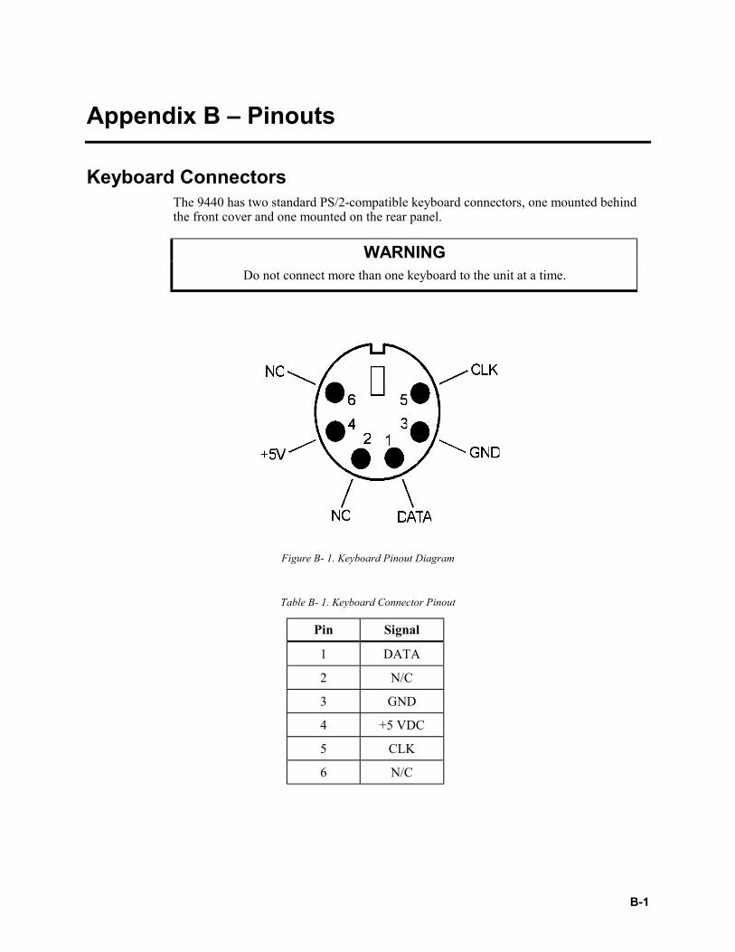
Keyboard ConnectorsThe 9440 has two standard PS/2-compatible keyboard connectors, one mounted behindthe front cover and one mounted on the rear panel.
WARNINGDo not connect more than one keyboard to the unit at a time.
Figure B- 1. Keyboard Pinout Diagram
Table B- 1. Keyboard Connector Pinout
Pin Signal
1 DATA
2 N/C
3 GND
4 +5 VDC
5 CLK
6 N/C
9440 Industrial PC/AT Rack Mount Computer
B-2
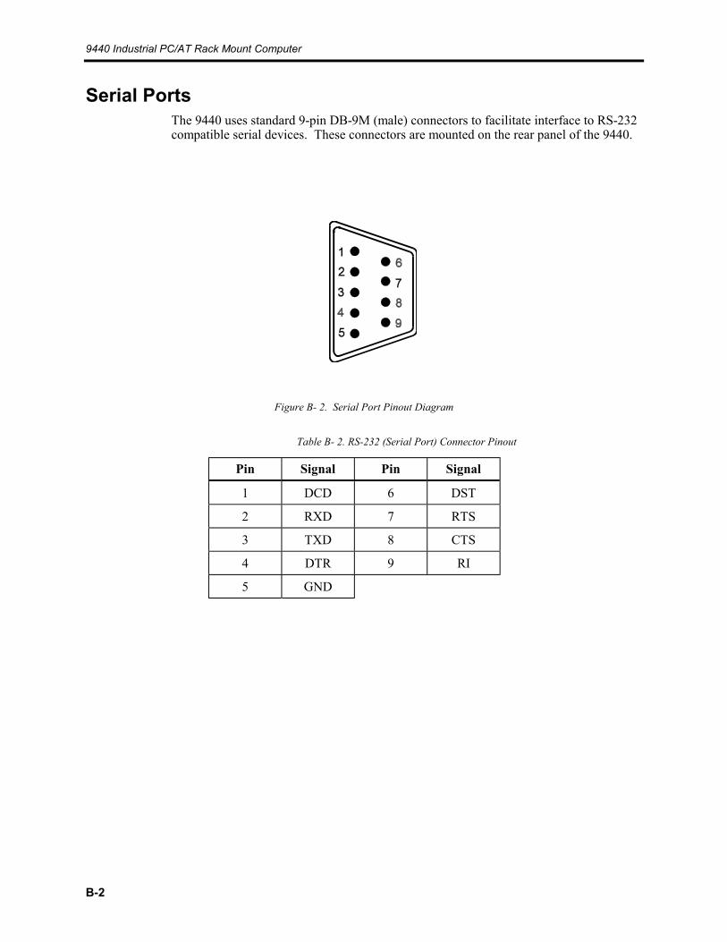
Serial PortsThe 9440 uses standard 9-pin DB-9M (male) connectors to facilitate interface to RS-232compatible serial devices. These connectors are mounted on the rear panel of the 9440.
Figure B- 2. Serial Port Pinout Diagram
Table B- 2. RS-232 (Serial Port) Connector Pinout
Pin Signal Pin Signal
1 DCD 6 DST
2 RXD 7 RTS
3 TXD 8 CTS
4 DTR 9 RI
5 GND

IndexAabout this manual, 1-1access knob, 1-3altitude, A-1auxiliary power pass-through outlet, 1-5
Ccase handles, 1-3CE marking, 1-7COM1 connector, 1-5COM2 connector, 1-5components, 1-2, 3-1
3.5" drive bays, 1-45.25" drive bay, 1-4back panel, 3-1front panel, 1-3, 3-1ISA backplane, 3-3ISA/PCI backplane, 3-2rear panel, 1-5
components, cleaning, 4-1configuration, 3-1connections, checking, 4-1CUL, 1-7current
drawn by system, A-2
Ddepth, A-2derating the power supply, 3-12diagnostic tests, 2-1drive bays, 1-4drive carrier bracket, 3-5, 3-6drives
installation, 3-5
Eelectrical specifications, A-2environment
electrical noise, excessive, 4-1power line noise, 3-8
environmental specifications, A-1altitude, A-1humidity, A-1shock, A-1temperature, A-1vibration, A-1
expansion cardsinstallation, 3-4
Ffan filter
cleaning, 4-1replacing, 4-2
fan intake filters, 1-4fan outlet grille, 1-5FCC, 1-7features, 1-1front panel components, 1-3
Hhandles, 1-3hard drive
activity LED, 1-3, 1-4hard drive activity LED, 1-3, 1-4hardware specifications, A-2
depth, A-2electrical, A-2height, A-2panel, A-2passive backplane, A-2weight, A-2width, A-2
height, A-2humidity, A-1
Iinstallation, 3-1, 3-7
cards and devices, 3-3drives, 3-5expansion cards, 3-4external hardware options, 3-12keyboard, 3-12mounting considerations, 3-7mouse, 3-12operating systems, 3-13processor card, 3-4rack, 3-10slide rails, 3-10
introduction, 1-1ISA backplane, 3-3ISA/PCI backplane, 3-2
Kkey lock, 1-3keyboard, 3-12
connector (front), 1-4connector (rear), 1-5pinout diagrams, B-1
9440 Industrial PC/AT Rack Mount Computer
Index -2
Lloopback connector, 2-2
Mmaintenance, 4-1
cleaning the case, 4-1connections, 4-1dusting, 4-1fan filter, 4-1location of noise generating equipment, 4-1preventive, 4-1replacing the fan filter, 4-2
mounting considerations, 3-7mouse, 3-12
Oon/off switch, 1-4opening the case, 3-3overview, 1-1
Ppinout diagrams, B-1
keyboard, B-1serial ports, B-2
poweravailable for expansion, 3-12excessive voltage, 3-9line noise, 3-8supply wiring practices, 3-8
power LED, 1-3, 1-4power receptacle, 1-5power switch, 1-4preparing the 9440 for use, 3-7processor card, installation, 3-4product repair, 5-1
Qquick start-up, 1-6
Rrear panel components, 1-5regulatory compliance, 1-7repair, 5-2
Sserial ports
COM1, 1-5COM2, 1-5loopback connector, 2-2pinout diagram, B-2
shock, A-1slide rails, 3-10spare parts, 4-1
spare parts list, 5-1speaker grille, 1-4specifications
environmental, A-1hardware, A-2keyboard pinout, B-1serial port pinout, B-2
Ttemperature, A-1testing, 2-1
UUL, 1-7unpacking the system, 1-2Vvibration, A-1
Wweight, A-2width, A-2
XXycom product repair, 5-1Xycom Repair Center, 5-2