course introduction and vhdl fundamentals (lecture #1) ece 331 – digital system design the slides...
TRANSCRIPT
Course Introductionand
VHDL Fundamentals
(Lecture #1)
ECE 331 – Digital System Design
The slides included herein were taken from the materials accompanying Fundamentals of Logic Design, 6th Edition, by Roth and Kinney,
and were used with permission from Cengage Learning.
Fall 2010 ECE 331 - Digital Systems Design 2
Course Introduction
Fall 2010 ECE 331 - Digital Systems Design 3
Course Info
Course #: ECE 331 Course Name: Digital Systems Design Course Objective:
To analyze and design combinational and sequential logic circuits.
To write VHDL code to describe and synthesize both types of circuits.
Course website: http://ece.gmu.edu/~clorie/Fall10/ECE-331/
Fall 2010 ECE 331 - Digital Systems Design 4
Instructor and TA's
Instructor: Craig Lorie Email: [email protected] Phone: (703) 993 – 9616 Office: Nguyen Engineering Bldg., Rm. 3221
TA: Ahmad Salman Email: [email protected]
TA: Smriti Gurung Email: [email protected]
Fall 2010 ECE 331 - Digital Systems Design 5
Textbook
Title: Fundamentals of Logic Design Edition: 6th Authors: Charles H. Roth
Larry L. Kinney
Fall 2010 ECE 331 - Digital Systems Design 6
Office Hours
Instructor: Craig Lorie TBA TBA
TA: Ahmad Salman TBA
TA: Smriti Gurung TBA
Fall 2010 ECE 331 - Digital Systems Design 7
The Lab (ECE 332) Labs performed weekly.
A total of eleven labs. Pre-lab must be completed prior to your lab
session. If you fail to complete the pre-lab you will not
be allowed to attend your lab session. Labs are administered by the TA's. ECE 332 must be taken in conjunction with ECE 331
or been previously completed with a C or better.
Fall 2010 ECE 331 - Digital Systems Design 8
Homework
Homework will be assigned on a weekly basis. Homework is due at the beginning of class on the
date specified (generally Thursday). No late submissions accepted.
Each assignment will consist of 8 problems. Two will be worth 35 points each; partial credit. Eight will be worth 5 points each; no partial credit.
Homework is essential to the learning process!
Fall 2010 ECE 331 - Digital Systems Design 9
Exams
Two exams during the semester. Final exam. All exams are closed-book.
No cheat-sheets. No make-up exams.
In the case of an emergency, see me. Notify me in advance (whenever possible) if
a conflict or problem exists.
Fall 2010 ECE 331 - Digital Systems Design 10
Grading
The final grade will be calculated as follows: Homework 15% Exam #1 25% Exam #2 25% Final Exam 35%
The grade for lab (ECE 332) is assigned separately.
The letter grade assignment is indicated in the syllabus.
Fall 2010 ECE 331 - Digital Systems Design 11
Attendance
Attending class is in your best interest! I will provide supplemental information to that
which is included in the textbook. I will go over a multitude of examples. I will answer questions.
However, attendance in lecture is NOT mandatory.
Attendance in Lab (ECE 332) IS mandatory.
Fall 2010 ECE 331 - Digital Systems Design 12
When emailing me, please format the subject line as follows:
“ECE331 - <last name> <first initial> - <subject>”
Fall 2010 ECE 331 - Digital Systems Design 13
Syllabus
Please see the class syllabus for more details.
(The syllabus can be found on the course website)
Fall 2010 ECE 331 - Digital Systems Design 14
Expectations
Fall 2010 ECE 331 - Digital Systems Design 15
You are expected to:
• Attend class (highly recommended).
• Spend a minimum of 9 hours each week outside of class learning the material.
• Read the text book.
• Do the homework.
• Attend the lab and complete all of the lab experiments.

Fall 2010 ECE 331 - Digital Systems Design 16
Questions?
Fall 2010 ECE 331 - Digital Systems Design 17
Materials to be covered ...
Chapter 10: Sections 1 – 9
Fall 2010 ECE 331 - Digital Systems Design 18
Introduction to VHDL
Fall 2010 ECE 331 - Digital Systems Design 19
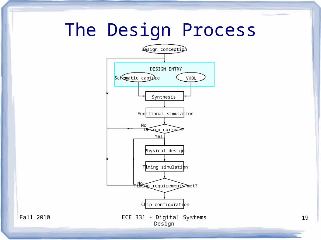
The Design ProcessDesign conception
VHDLSchematic capture
DESIGN ENTRY
Design correct?
Functional simulation
No
Yes
No
Synthesis
Physical design
Chip configuration
Timing requirements met?
Timing simulation
Fall 2010 ECE 331 - Digital Systems Design 20
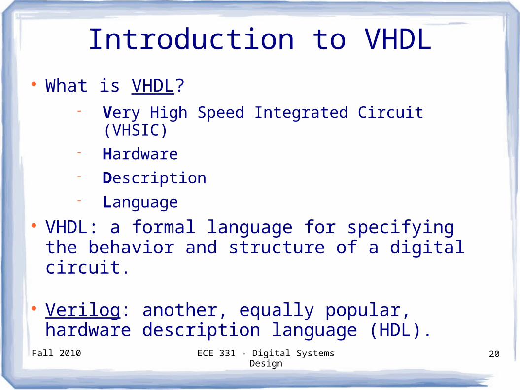
Introduction to VHDL What is VHDL?
Very High Speed Integrated Circuit (VHSIC) Hardware Description Language
VHDL: a formal language for specifying the behavior and structure of a digital circuit.
Verilog: another, equally popular, hardware description language (HDL).
Fall 2010 ECE 331 - Digital Systems Design 21
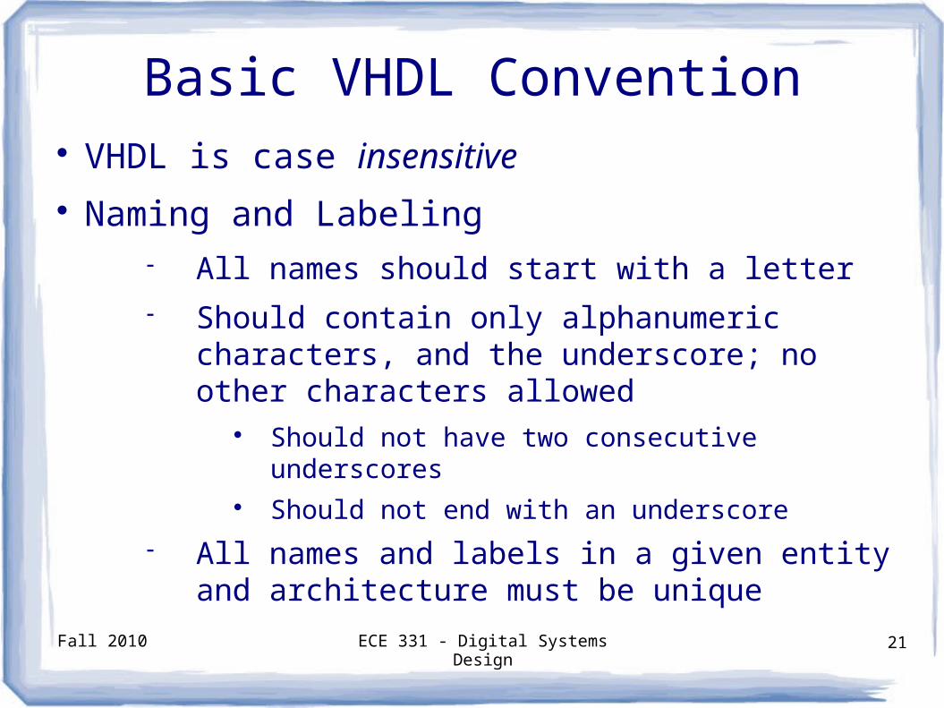
Basic VHDL Convention VHDL is case insensitive Naming and Labeling
All names should start with a letter Should contain only alphanumeric characters,
and the underscore; no other characters allowed
Should not have two consecutive underscores Should not end with an underscore
All names and labels in a given entity and architecture must be unique
Fall 2010 ECE 331 - Digital Systems Design 22
Basic VHDL Convention
Free format language i.e. allows spacing for readability
Comments start with “--” and end at end of line Use one file per entity File names and entity names should match
Fall 2010 ECE 331 - Digital Systems Design 23
Logic Circuits in VHDL
VHDL description includes two parts Entity statement Architecture statement
Entity Describes the interface (i.e. inputs and outputs)
Architecture Describes the circuit implementation
Fall 2010 ECE 331 - Digital Systems Design 24
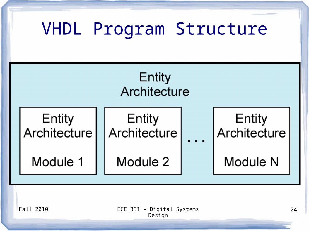
VHDL Program Structure
Fall 2010 ECE 331 - Digital Systems Design 25
The Entity Statement
Keyword: Entity Requires a name Specifies the input and output ports
Ports have Name Mode Data type
Fall 2010 ECE 331 - Digital Systems Design 26
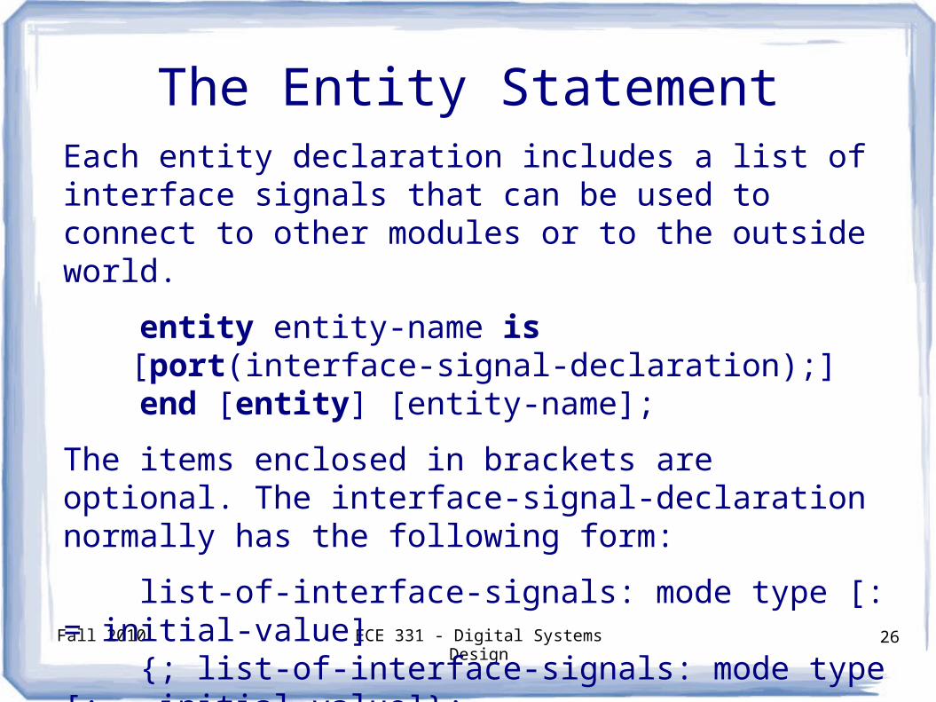
Each entity declaration includes a list of interface signals that can be used to connect to other modules or to the outside world.
entity entity-name is[port(interface-signal-declaration);]
end [entity] [entity-name];
The items enclosed in brackets are optional. The interface-signal-declaration normally has the following form:
list-of-interface-signals: mode type [: = initial-value] {; list-of-interface-signals: mode type [: = initial-value]};
The Entity Statement
Fall 2010 ECE 331 - Digital Systems Design 27
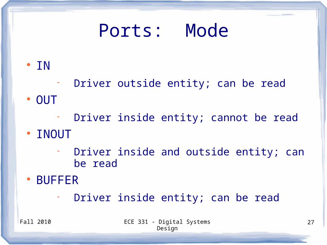
Ports: Mode
IN Driver outside entity; can be read
OUT Driver inside entity; cannot be read
INOUT Driver inside and outside entity; can be read
BUFFER Driver inside entity; can be read
Fall 2010 ECE 331 - Digital Systems Design 28
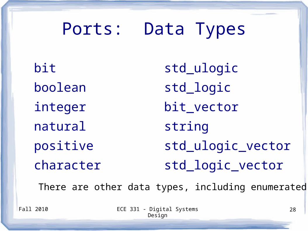
Ports: Data Types
bit
boolean
integer
natural
positive
character
std_ulogic
std_logic
bit_vector
string
std_ulogic_vector
std_logic_vector
There are other data types, including enumerated types.
Fall 2010 ECE 331 - Digital Systems Design 29
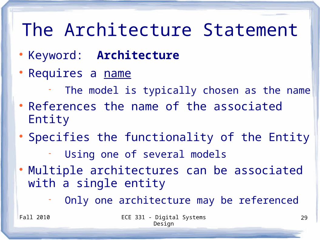
The Architecture Statement Keyword: Architecture Requires a name
The model is typically chosen as the name References the name of the associated Entity Specifies the functionality of the Entity
Using one of several models Multiple architectures can be associated with a
single entity Only one architecture may be referenced
Fall 2010 ECE 331 - Digital Systems Design 30
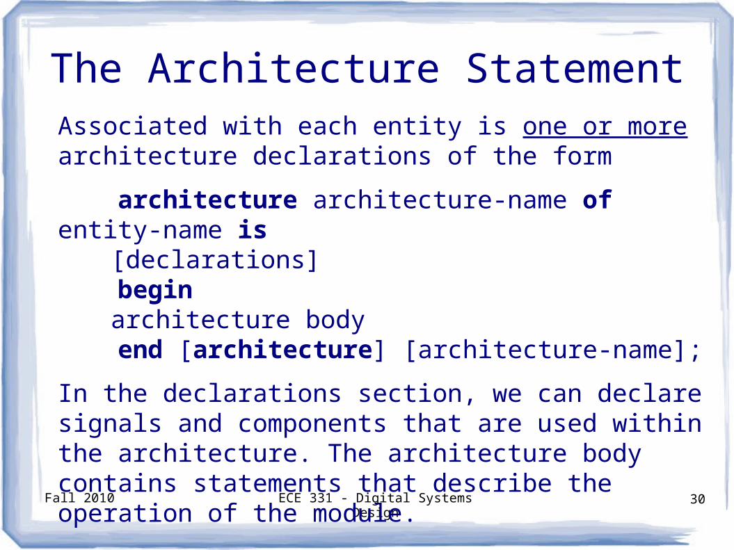
The Architecture StatementAssociated with each entity is one or more architecture declarations of the form
architecture architecture-name of entity-name is[declarations]
beginarchitecture body
end [architecture] [architecture-name];
In the declarations section, we can declare signals and components that are used within the architecture. The architecture body contains statements that describe the operation of the module.
Fall 2010 ECE 331 - Digital Systems Design 31
Signals
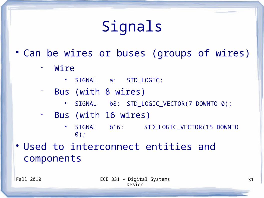
Can be wires or buses (groups of wires) Wire
SIGNAL a: STD_LOGIC;
Bus (with 8 wires) SIGNAL b8: STD_LOGIC_VECTOR(7 DOWNTO
0);
Bus (with 16 wires) SIGNAL b16: STD_LOGIC_VECTOR(15 DOWNTO
0);
Used to interconnect entities and components
Fall 2010 ECE 331 - Digital Systems Design 32
Signal Assignment
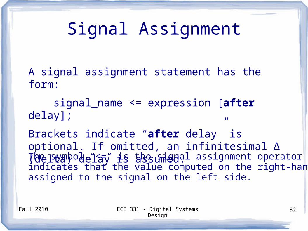
A signal assignment statement has the form:
signal_name <= expression [after delay];
Brackets indicate “after delay” is optional. If omitted, an infinitesimal ∆ (delta) delay is assumed.
The symbol “<=“ is the signal assignment operator which indicates that the value computed on the right-hand side is assigned to the signal on the left side.
Fall 2010 ECE 331 - Digital Systems Design 33
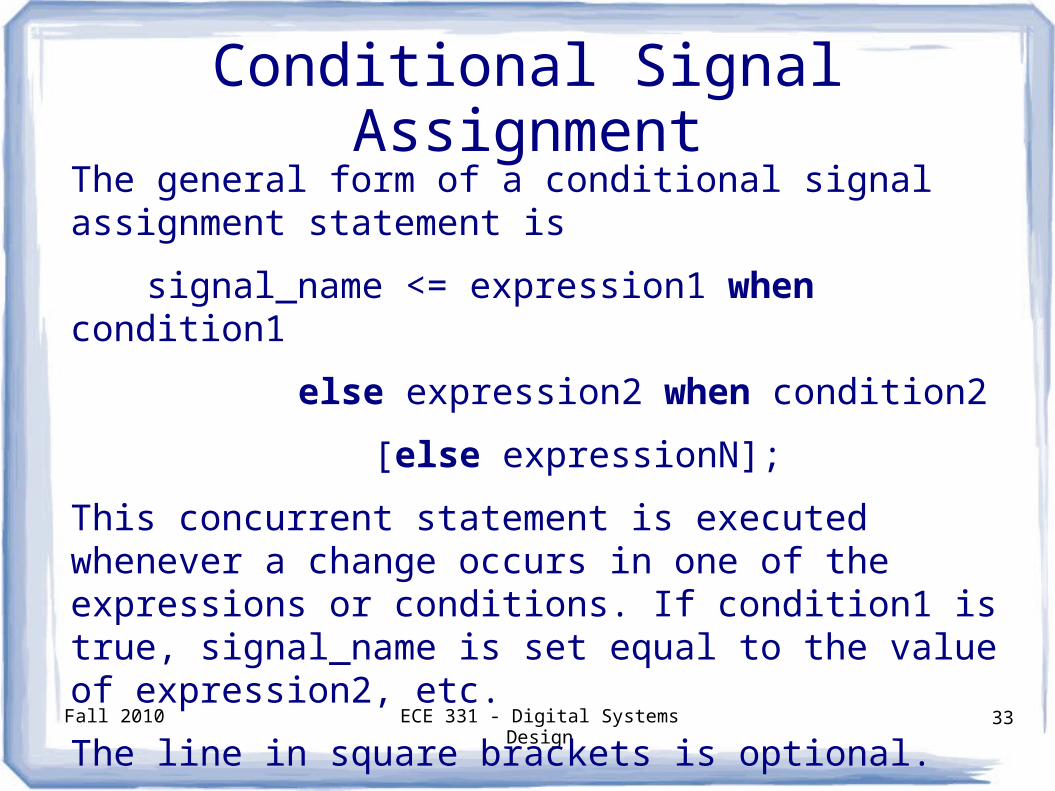
Conditional Signal AssignmentThe general form of a conditional signal assignment statement is
signal_name <= expression1 when condition1
else expression2 when condition2
[else expressionN];
This concurrent statement is executed whenever a change occurs in one of the expressions or conditions. If condition1 is true, signal_name is set equal to the value of expression2, etc.
The line in square brackets is optional.
Fall 2010 ECE 331 - Digital Systems Design 34
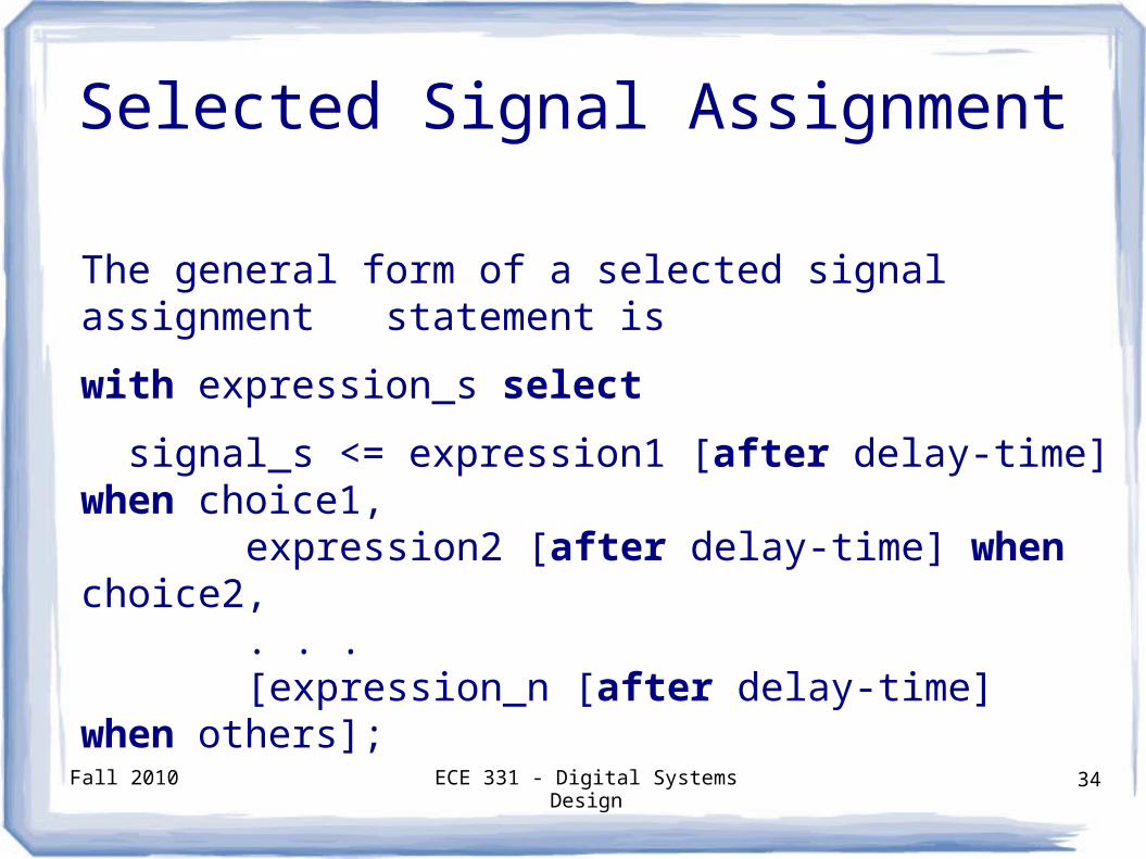
Selected Signal Assignment
The general form of a selected signal assignment statement is
with expression_s select
signal_s <= expression1 [after delay-time] when choice1,expression2 [after delay-time] when choice2,. . .[expression_n [after delay-time] when others];
Fall 2010 ECE 331 - Digital Systems Design 35
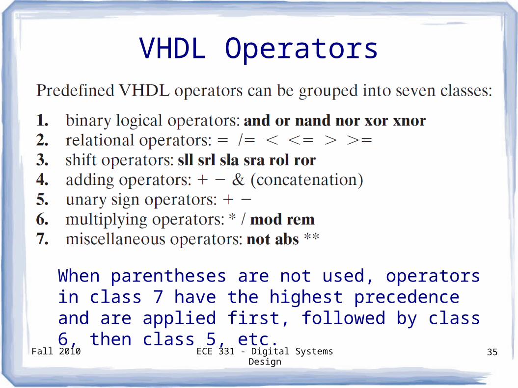
VHDL Operators
When parentheses are not used, operators in class 7 have the highest precedence and are applied first, followed by class 6, then class 5, etc.
Fall 2010 ECE 331 - Digital Systems Design 36
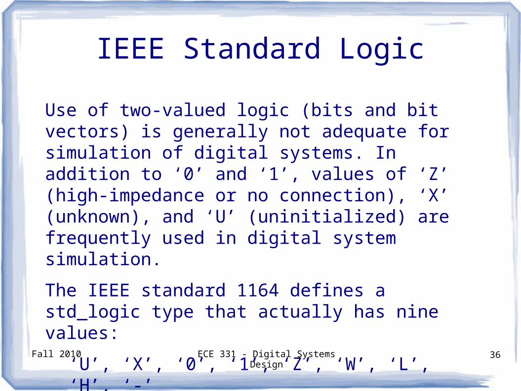
IEEE Standard Logic
Use of two-valued logic (bits and bit vectors) is generally not adequate for simulation of digital systems. In addition to ‘0’ and ‘1’, values of ‘Z’ (high-impedance or no connection), ‘X’ (unknown), and ‘U’ (uninitialized) are frequently used in digital system simulation.
The IEEE standard 1164 defines a std_logic type that actually has nine values:
‘U’, ‘X’, ‘0’, ‘1’, ‘Z’, ‘W’, ‘L’, ‘H’, ‘-’
Fall 2010 ECE 331 - Digital Systems Design 37
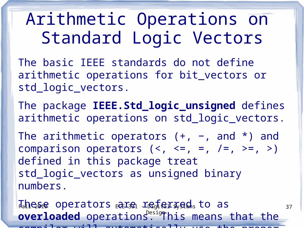
Arithmetic Operations on Standard Logic Vectors
The basic IEEE standards do not define arithmetic operations for bit_vectors or std_logic_vectors.
The package IEEE.Std_logic_unsigned defines arithmetic operations on std_logic_vectors.
The arithmetic operators (+, −, and *) and comparison operators (<, <=, =, /=, >=, >) defined in this package treat std_logic_vectors as unsigned binary numbers.
These operators are referred to as overloaded operations. This means that the compiler will automatically use the proper definition of the operator depending on its context.
Fall 2010 ECE 331 - Digital Systems Design 38
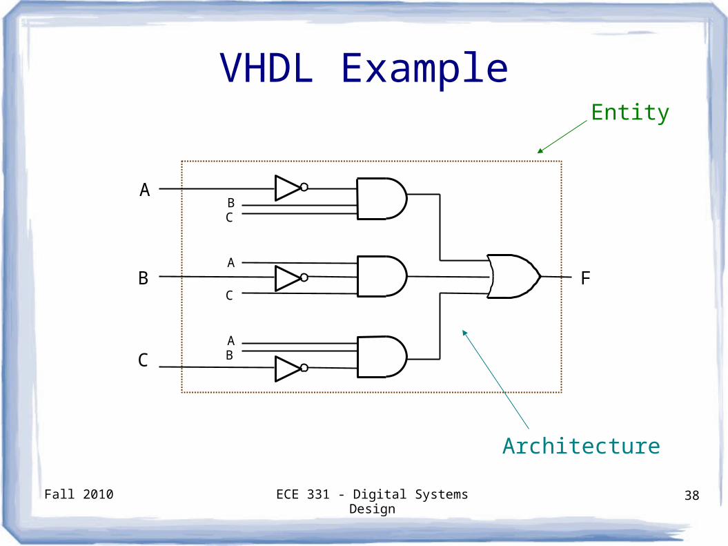
VHDL Example
F
A
B
C
BC
AB
A
C
Entity
Architecture
Fall 2010 ECE 331 - Digital Systems Design 39
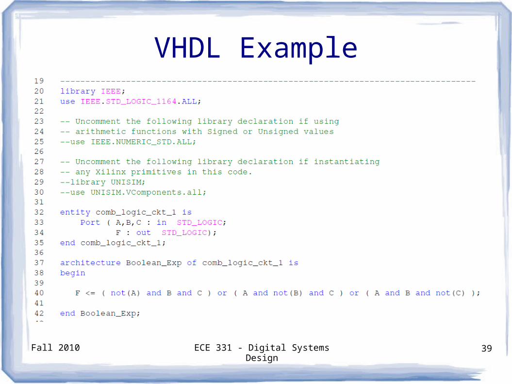
VHDL Example
Fall 2010 ECE 331 - Digital Systems Design 40
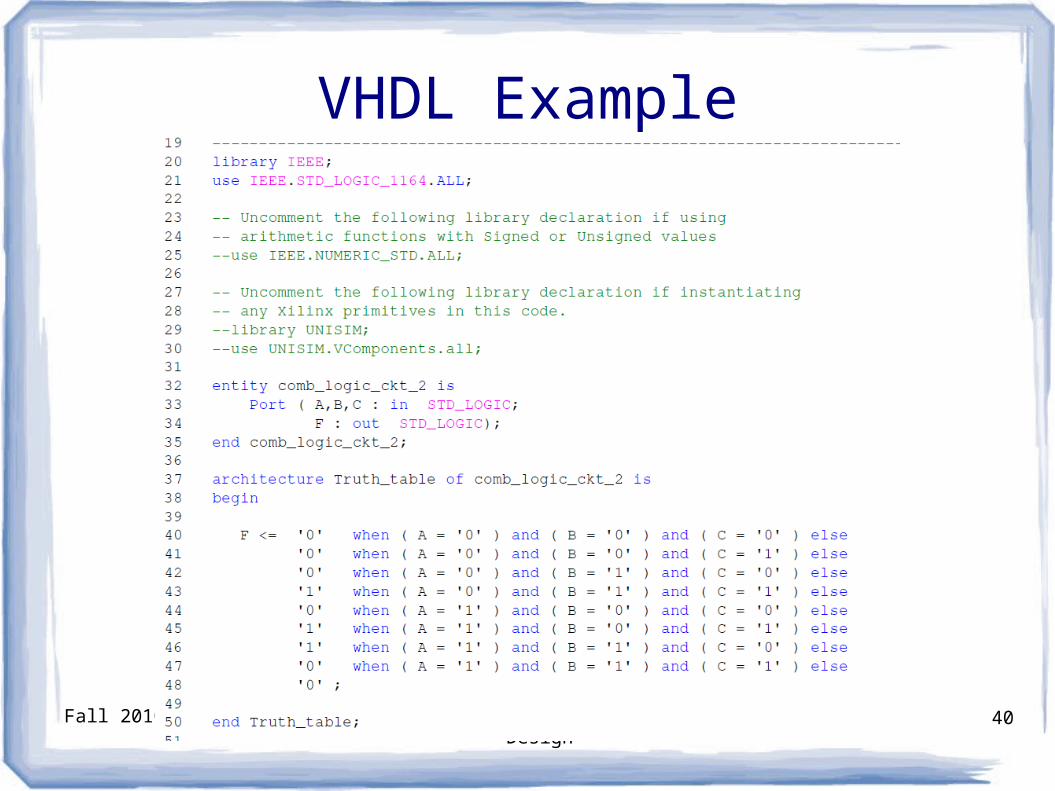
VHDL Example
Fall 2010 ECE 331 - Digital Systems Design 41
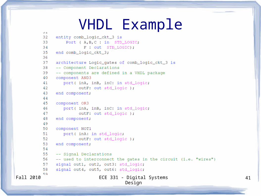
VHDL Example

Fall 2010 ECE 331 - Digital Systems Design 42
VHDL Example (continued)

Fall 2010 ECE 331 - Digital Systems Design 43
Questions?