coupled-cavity traveling-wave parametric i...
TRANSCRIPT

PROCEEDINGS OF THE IRE
Thus, the series expression for the potential on the axis(y =- 0), derived in the same manner as the series expression for the potential of the vertical deflection field,leads to
2 0
- (V2 - VI) E (-1) exp ±(2n + 1)7rx/d} x O0d nA=3O
2(V2 - 1j) r7x/d/(1 + e2x/d)
d
=(1/d)(V2 -V1) sech (irx/d)The focusing properties of this lens are obtained by in-tegrating the paraxial equation9
ft 4)/Y+4)I"y2¢f
9 Zworykin, et al., op. cit., see (12.12) on p. 402. The expressionlsfor the focal lengths and principal plane positions of a weak lens areobtainied by integrating the path equation first with y=const anidthen integrating it again, treating the deviation of y from its initialvalue as a small quantity, found in the first integration.
For weak lenses [(V2- V1)/(1V2+ V1)<< the imageanid object-side focal lengths fi and fo aind the distanceh of the principal plane from the junctioni plane (iimageand object-side principal planes coincide approxi-mately) are given by
V2 + VI\2 2V2 \1/2wdfI,= V2 VI V2+ VI 4
(V~~2l7+ ) (2wmd
V2 1F+ V I 4
V2 + 4rd
V2 V 4
ACKNOWLDEGMENT
The author gratefully acknowledges the encourage-ment received from Dr. D. W. Epstein, at whose suggestion the analysis was carried out, as well as the ilnvalu-able assistance of Dr. F. Edelman, who programmedthe numerical problems and supervised the mnachinecomputation required
Coupled-Cavity Traveling-Wave ParametricAmplifiers: Part I-Analysis*
M. R. CURRIEt, SENIOR MEMBER, IRE, AND R W. GOULD t, MEMBER, IRE
Summary-A general class of traveling-wave parametric ampli-fiers based on coupled-cavity filter circuits is described. This type ofamplifier is particularly suited to microwave frequencies and in-corporates new features that overcome some severe difficulties asso-ciated with other circuit structures. Traveling-wave diode-type am-plifiers having relatively wide bandwidths and great simplicity atS band have already resulted from this approach (details of experi-ments will be described in Part II).
An analysis is presented which provides detailed information onoperating characteristics, including the effects of terminal imped-ances, reflected waves, circuit loss, etc., and also leads to a simplephysical picture of the cumulative interaction mechanism in terms ofcoupled-mode concepts. This physical picture is emphasized through-out this paper. Gain bandwidth considerations are discussed in termsof a fundamental "interaction-impedance" parameter.
Representative calculated curves show that unilateral gains of12 to 15 db over relatively wide bandwidths are attainable with asfew as 4 to 6 diodes. Methods of increasing the gain through use offerrites and special circuit techniques are proposed.
* Received by the IRE, May 3, 1960; revised manuscript received,August 19, 1960. This work was presented at the Seventeenth AnnualConf. on Electron Device Res., Mexico City, Mexico; June, 1959.
t Hughes Res. Labs., A Division of Hughes Aircraft Co., Malibu,Calif.
t Calif. Inst. Tech., Pasadena, Calif.
INTRODUCTION
A1\ GREAT deal of attention currently is being givento increasing the bandwidth capabilities of solid-state parametric amplifiers by application of
traveling-wave circuit techniques. In many respects,this situation is reminiscent of the evolution of broad-band traveling-wave tubes from klystron amplifiers employing resonant cavity circuits. As will be shown inthis paper, this analogy not only provides much usefulconceptual information but also suggests a specific an-alytical and experimental approach which already hasresulted in traveling-wave diode-type parametric am-plifiers having relatively wide bandwidths and greatsirnplicity at microwave frequencies.
Following the analysis of Tien and Suhl12 of para-metric am plification in, a uniformly distributed non.-
' P. K. Tien, "Parametric amplification and frequency mixing inpropagating circuits," J. Appl. Phys., vol. 29, pp 1347 1357; Sep-tember, 1958.
PP. K. Tien and H. Suhl, "A traveling wave ferromagnet-ic amplifier," PROc IRE, vol. 46, pp. 700-706; April, 1958.
1960 DecemYber

1960 Currie and Gould: Coupled-Cavity Traveling- Wave Parametric Amplifiers: Part I-A nalysis
dispersive medium, Engelbrecht demonstrated an ex-perimental amplifier in the UHF region which approxi-mated Tien's model and resulted in excellent bandwidthperformance.3 This amplifier was based on a uniformtransmission line (coaxial TEM mode) in which thenonlinear capacitive diodes were placed very close to-gether with respect to wavelength so as to approximatea uniform nonlinear medium. Although the diodes wereindividually tuned for optimum performance, the es-sential nondispersive nature of the TEM mode wasnot changed.
In attempting to extrapolate directly this uniformtransmission line approach to the microwave fre-quency range (S band and above) difficulties have beenencountered which probably can be attributed to severalfactors.
First, the relatively low "interaction impedance" ofsuch structures (in terms of voltage (leveloped acrossthe diode per unit power flow) implies a low gain perdiode. With a large number of diodes, any noonuniform-ity in their characteristics can seriously affect amplifiergain. The diode losses also attenuate the pump poweras it propagates down the system, which further re-duces the contribution to gain of successive diodestages.
Second, such circuits can propagate some of thehigher-order frequency components generated by mix-ing of the signial and the pump. In such systems, asshown recently by Roe and Boyd,4 exponential gainat the signial frequency may not occur; rather, energyconversion to the propagating cross-product frequenciescanl take place with very little gain at the signal fre-quenlcy.
Finally, at microwave frequencies, the lead induct-ance associated with the diode, together with its straycapacitance, can establish a self-resonance at or belowthe operating frequency of the amplifier. In this case,the voltage that is developed across the capacitivep-n junctioni itself may be greatly reduced with conse-quent severe degradation of amplifier performance.
This paper is concerned with a class of iterative cir-cuits for traveling-wave parametric amplifiers whichovercomes the first two difficulties and alleviates thethird. It permits the realization of simple high-gain,broad-band parametric amplifiers at microwave fre-quencies.The basic model is shown schematically in Fig. 1. It
conlsists of a chain of inductively coupled cavities; eachcavity is loaded by a diode in the capacitive region, andthe diodes are individually pumped from an externalcircuit with the pump phase arranged so as to simulatea traveling wave. Some of the advantages of this gen-eral type of circuit are as follows:
3 R. S. Engelbrecht, "A low-noise nonlinear reactance travelingwave amplifier," PROC. IRE, vol. 46, p. 1655; September, 1958.
4G. M. Roe and M. R. Bovd, "Parametric energy conversion indistributed systems," PROC. IRE, vol. 47, pp. 1213-1218; July, 1959.
Fig. I-Sketch of coupled-cavity type of traveling-wave parametricamplifier. Waves at the signal and idler frequencies propagatethrough a filter chain of inductively coupled cavities. Each cavityis loaded by a variable-capacitance diode at a position of maxi-mum electric energy storage. Pump power is introduced from aparallel-feed system.
1) Since the structure constitutes a microwave banid-pass filter circuit, the problems associated with thepropagation of higher-frequency components are elim-inated; these components can be made to fall in stopbands of the filter, where they cannot propagate andabsorb energy.5
2) Unlike the case in which a uniform line is loadledby diodes, the diodes in this model are placed only inregions of concentrated electric energy storage. A highervoltage is developed across the nonlinear capacitanicefor a given power flow in the circuit. As a consequence,the gain per diode can be considerably higher than in theuniform case; the amplifier is greatly simplified by re-quiring fewer stages and lower pump power. As will bediscussed, this situation can also be regarded from amore general viewpoint; a relation exists between gainper diode and ban-dwidth much like that between gaitiper unit length and bandwidth in traveling-wave tubes.By restricting the bandwidths to essentially the requiredvalue by means of a filter circuit, the gain per stage canbe maximized.
3) The coupled-cavity circuit is particularly welladapted to microwave frequenicies because it providesreasonably large diode spacings even at short wave-lengths. For example, a direct scaling of Engelbrecht'samplifier, in which the diodes are spaced by 8 wave-length at the signal frequency, would lead to prohibi-tively small spacings in the microwave region.
4) The circuit is a natural structure for incorporatinigferrite elements as a possible means of improving sta-bility by obtaining nonreciprocal atteniuation. Theregions of magnetic and electric energy storage areseparated spatially so that elements sensitive to bothelectric and magnetic fields may be most effectivelyutilized in the amplifier design.
5) The use of parallel pumping permits efficienit useof the available pump power and provides in-dependentexternal adjustment of phase shift between sectioiis soas to optimize gain, frequency response, and reverseattenuation.
6) The lead inductance of the diodes can be inicorpo-rated as part of the individual cavity circuits, thus
6 When the pumping is not too strong, the diode elastance variesessentially sinusoidally with time. It is only necessary then to sup-press the next highest idler (sum of signal and pump frequencies) toeliminate the effects of all other idlers.
1960 1961

6PROCEEDINGS OF THIE IRE
alleviating some of the problems associated with selfresonance of the diode package.The purpose of this paper is to describe the operation
of filter-circuit traveling-wave parametric amplifiersof the type discussed above and to present an analysisthat has proved very valuable in understanding some oftheir detailed characteristics. Certain aspects of thisanalysis aie related to that of Bell and Wade' for thecase of uniform transmissiorn lines which are periodi-cally loaded by diodes. A companion paper presents results of an experimenital program in which these ideashave been (lemonstrated and extended by adding sev-eral features niot incorporated in the basic model.We shall first discuss the properties of coupled-cavity
circuits and give a qualitative picture of the conditionsundier which an idler wave, which closely couples to thesignal wave arid leads to exponential growth, can. begenerated. The subsequenlt analysis is based on arequivalent circuit that closely represents the characteristics of its coupled-cavity microwave analog. Theanalytical approach has the advantage of taking intoaccount the effects of terminial impedances and reflectedwaves an(l loss, all of which are of first-order importancein amplifier design. Detailed results of computer calculationis (learly illustrate the essential characteristics ofthis type of amplifier and point up certain basic similarities with traveling-wave tubes. Finally, this approachis related to that of Tieii in terms of a fundamentalniew interaction-impedanice parameter.
other possible iterated circuits of the general type indi-cated in Fig 1.
IL discussing the model, it is useful to define the fol-lowing dimensionless parameters:
X v LC0 (1)
is frequency normalized to the midband frequency(LCQ) 1/2 of the cold filter circuit-
k MEL (2)
is the coefficient of coupling between cavities,
q( = R
YL (3)
is the reciprocal resonator Q and provides a measure ofresistive circuit loss. (Note that C0 =/S,e)
1 he general properties of the model are indicated inthe Brillouin diagram of Fig. 3 We will use this repre-sentationi throughout as a convenient means for studying the properties of amplifiers of the filter-circuit type.Here we have assumed that k is positive. For negativek, the fundamental branch would be a backward wave,but this would not alter the nature of the problem.The abscissa 0 is the phase shift per resonator corre-sponding to a dependence
.= l, exp ( a -
i ) (4)
DiSCUSSION OF MODEL AND ANALYSIS
An equivalent-circuit representation of the coupledcavity traveling-wave paramietric amplifier is shown inFig. 2e This particular circuit was chosen for analysisbecause it has been successfully applied in studyingsimilar problems for traveling-wave-tube amplifiers.7In both cases, the basic cavity circuit elements aredesigned so as to concentrate the electric-energy storage at the point of active interaction (whether the inter-action occurs with a time-varying capacitance or withan electron beam) and the cavities are inductivelycoupled. For fractional bandwidths less than about 25per cent, this equivalent circuit can provide an accuratequantitative description of the characteristics of theactual distributed microwave circuit. This has beenestablished by exteIlsive measurements. For increasingbandwidths, the quantitative accuracy is not as good be-cause of the use of frequency-independent elements inthe equivalent circuit. However, the representation con-tains all the essenitials of the physical problem, and theresults of the analysis apply in a qualitative way to
6 C. V. Bell and G. Wade, "Circuit considerations in travelingwave parametric amplifiers," 1959 I RE WESCON CONVENTIONRECORD, pt. 2, pp. 75-82.
7 R. W. Gould, "Characteristics of traveling wave tubes withperiodic circuits,' IRE TRANS. ON ELECTRON DEVICES, vol. ED-5,pp. 186-195; July, 1958.
where a is a measure of the circuit loss. The upper and
-S0+= cos(w@ t-ne)
Fig. 2-Equivalent circuit of coupled-cavity traveling-wave para-metric amplifier including arbitrary terminal impedances. Thetime variation of elastance of the nth cavity is indicated; SO 1/,C,where C0 is the combined localized static capacitance of cavityand diode.
STOPBAND
SMPBfND a
r-2 r w I U rt
- t *[email protected] --
-jFUNIDAMENTAL ;BRANCH
Fig. 3- Brillouin diagram of coupled-cavity filter circuit; X is normalized frequency, 0 is phase shift per section. Both the positiveand negative frequency passbands are shown.
-~~~~~~~~
1962 D"ecember
f% -.&
10 Currie and Gould: Coupled-Cavity Traveling- Wave Parametric Amplifiers: Part I-A nalysis
lower cutoff frequencies of the pass bai
1,Xupper = J 1 + klower
VT2k
nd are given by
(k << 1), (5)
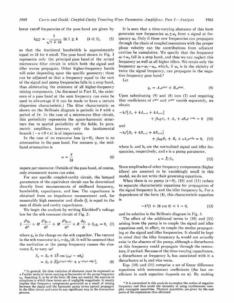
so that the fractional bandwidth is approximatelyequal to 2k for k small. The pass band shown in Fig. 3represents only the principal pass band of the actualmicrowave filter circuit in which both the signal andidler waves propagate. Other higher-frequency bandswill exist depending upon the specific geometry; thesecan be adjusted so that a frequency equal to the sumof the signal and pump frequencies falls in a stop band,thus eliminating the existence of all higher-frequencymixing components. (As discussed in Part II, the exist-ence of a pass band at the sum frequency can even beused to advantage if it can be made to have a certaindispersion characteristic.) The filter characteristic asshown on the Brillouin diagram is periodic in 6 with aperiod of 2r. In the case of a microwave filter circuit,this periodicity represents the space-harmonic struc-ture due to spatial periodicity of the fields. In para-metric amplifiers, however, only the fundamentalbranch (-wr <6w< r) is of importance.
In the case of no resonator loss (q = 0), there is noattenuation in the pass band. For nonzero q, the mid-band attenuation is
qa =
2k (6)
nepers per resonator. Outside of the pass band, of course,only evanescent waves can exist.
For any specific coupled-cavity circuit, the lumpedparameters of the equivalent circuit can be determineddirectly from measurements of midband frequency,bandwidth, capacitance, and loss. The capacitance isobtained from an impedance measurement and, forreasonably high resonator and diode Q, is equal to thesum of diode and cavity capacitance.We begin the analysis by writing Kirchhoff's voltage
law for the nth resonant circuit of Fig. 2:
d2qn d2qn-1 d2qn±i dqnL + A -+M +R +Snqn-0 (7)
dt2 dt2 dt2 dt
where q,, is the charge on the nth capacitor. The currenitin the nth resonator is i, ==dqn/dt. It will be assumed thatthe excitation at the pump frequency causes the elas-tance S. to vary as'
Sn = So + 2S cos (Cowt - no')= So + ..[ei(wpt nflOp) + e-i(tnOtp)I (8)
8 In general, the time variation of elastance must be expressed asa Fourier series of terms varying at harmonics of the pump frequencycap. Assuming Sn to be of the form (8) does not restrict the analysis tosituations in which these terms are of negligible magnitude. It merelyimplies that frequency components generated as a result of mixingbetween the signal and the harmonic pump terms cannot propagatein the filter circuit and enter in any significant way in the interactionprocess.
It is seen that a time-varying elastance of this formgenerates new frequencies coi±w, from a signal at fre-quency w1, Only if these new frequencies can propagatethrough the chain of coupled resonators with the properphase velocity can the contributions from adjacentcavities be cumulative. We specify that the frequencyco1+w fall in a stop band, and thus we can neglect thisfrequency as well as all higher idlers. We retain only thefrequency (02 WI - w,, which, if wc is in the vicinity oftwice the signal frequency, can propagate in the nega-tive frequency pass band.9
Let
qn = A.eilil + Bneiw2t. (9)
UJpon substituting (9) and (8) into (7) and requiringthat coefficients of eilt and ein2t vanish separately, weobtain
-1,12[A, + kAni + kAn+1+jXlqAn + An + eBneCin =p 0 (10)
and
-X22[Bn + kBn1 + kB,n+±]+ jXqBn + Bn + EAneinop0, (11)
where Xi and X2 are the normalized signal and idler fre-quencies, respectively, and e is a pump parameter,
e= S/S0. (12)
Since amplitudes of other frequency components (higheridlers) are assumed to be vanishingly small in thismodel, we do not write their governing equations.When there is no pump (e=0), (10) and (11) reduce
to separate characteristic equations for propagation ofthe signal frequency Xi and the idler frequency X2. For adependence of the form (4), this characteristic equationis
-.}2(1 + 2k cos 0) + 1 = 0, (13)
and its solution is the Brillouin diagram in Fig. 3.The effect of the additional terms in (10) and (11)
arising from the pump is to couple the signal and idlerequations and, in effect, to couple the modes propagat-ing at the signal and idler frequencies. It should be keptin mind that the idler frequency X2 would not actuallyexist in the absence of the pump, although a disturbanceat this frequency could propagate through the resona-tors, if excited. Because of the time-varying capacitance,a disturbance at frequency X2 has associated with it adisturbance at Xi and vice versa.
Eqs. (10) and (11) comprise a set of linear differenceequations with nonconstant coefficients (the last co-efficient in each equation depends on n). By making
9 It is convenient in this analysis to employ the notion of negativefrequency and thus avoid the necessity of using cumbersome com-plex conjugate quantities. Physical quantities are given by the realparts of the expressions thus obtained.
1960 1963

1PROCEEDINGS OF THE IRER
the substitution Bn -B' nCej?OP, however, a set of constant coefficient equations is obtained:
-,2X12[A, + kAn 1l+ kA.r1]+jqXAn + An + efBn 0 (14)
X22[B'n + ke i0PB',,1 + ke+±iPB',+,±+jqX2B'n + B'n + A, 0. (15)
We interpret B'n as follows. A signal at W2 would bedescribed by qn eiW2IB,,. The time-varying capacitor (8)generates a voltage at frequency wi given by
SejoltB,,e'np=lebwBln
Thus the variation of the phase of this converted signalis contained in the factor B', In the limit of a very weakpump, B'ne- where 02 iS the phase shift of thecircuit at Cw2.To solve (14) and (15), we assume the solution to be
of the form An-=Ao0n, B'n,=B',,n, where ,I is a complexconstant. In the earlier discussion of the characteristicsof the cold circuit, we let M=e-(a,i+), where a and 0 arethe atteniuation and phase shift per section, respectively.For a solution, IA must satisfy the determinantal equation
X12 t1 + ' k1) + jqXi + 1
X21 + -\ +kIeJO+j+X2 +1J- 0. (t6)
For each value of X1, this equation is satisfied by fourdifferent values of Au. The solutions for q=O, E-0 areparticularly simple and have been previously discussed.The first factor in (16) leads to the usual dispersioncurve, which is repeated as the solid curve in Fig. 4.The second factor has the same form as the first if wewrite pu, .Ve20P, Thus, a curve of X2 Vs 6' is identical inform to the solid curves of Fig. 4.
It is useful to express the latter solution in terms ofX1 and 06 Noting that XI X2 +Xp and 0 60'+6p, we canconstruct the second set of solutions from the first bysimply displacing the solid curve of Fig. 4 upward byan amount Xp and to the right by an amount Op. Thisresults in the dashed curves shown.We are now in a position to give a simple physical
picture of the traveling-wave interaction mechanismand an interpretation of this analysis. We may regardthe dashed curves in Fig. 4 as giving the phase shift persection of a disturbance at Xi, which would result fromthe conversion of a signal at X2 by a very weak pump(e small). If this phase shift coincides with the nornmalphase of the circuit at Xi (as given by the solid curve),then the converted signal can propagate along the cir-cuit in phase with the signal at XI and a cumulativeeffect from section to section will exist. We expect thiseffect to be strongest and the gainto be maximum
POSITIVE FREQUENCY PASSB
NEGATIVE FREQUENCY SSOAS SHFTED BY PUMP
-2w -w
x
L POSITIVE FREQUENCY PASSBANDAS SHIFTED BY PUMP
. \
REGON OF STRONG INTERACTION
0 vw 7
NEGATIVE FREQUENCY PASSBAND
Fig. 4-Generation of the "idler curve," showing the phase shift persection of a wave at X1, which resuilts from conversion of a waveat X2 (idler frequency) by mixing with a weak pump. The idleicturve is generated by translating the negative frequency disper-sion curve to the right by a distance O, and vertically upwardby X,,.,A higher order idler curve is also shown; it falls in a stopband of the filter circuit.
when the solid and dashed curves of Fig. 4 coincide. Atthis point
0(X2) + O6 (XI)j (17)where 2=Xi-X,. This is just the relation found byTieni except for the change in the signs preceding X2and 0(X2)9 which arises from our use of negative frequencies.The range of frequency over which the solid aid
dashed lines of Fig. 4 nearly coincide determines thebandwidth over which traveling-wave parametric amn-plification can be obtained The diffeietce in phaseshifts that can be tolerated and still have amplificationincreases as the pump parameter e is increased. Thiswill be illustrated in detail later.The above description bears a close analogy to the
theory of coupling of modes of propagationio ii and, aswill be discussed in the next section, has proved to bevery useful in understanding some of the detailed char-acteristics of iterated traveling-wave parametric am-plifiers as they result from the present analysis.A complete solution of the problem is given by a
superpositiorn of the four wave solutions; i.e.
4 4
qn = AorFlreic1tt+ Bor eJ"5P;LeJ" (l8ori1 ri
gives the charge on the nth capacitor. The four complexroots of the determinantal equation are /uzi . . A4, anidA0l v e A04 are arbitrary constants, which are determined by the boundary conditions of the nuodel; B'ois related to Aor by means of (14) The current in the nth
10 J. R. Pierce, "Coupling of modes of propagation," J. Appl.Phys., vol. 25, p. 179; February, 1954.
11 J. R. Pierce and P K. Tien, "Coupling of modes in helices,"PROC. IRE, vol. 42, p. 1389; September 1954.
1964 December

Currie and Gould: Coupled-Cavity Traveling-Wave Parametric Amplifiers: Part I-A nalysis
resonator circuit is therefore given by
in = LIorrn eiwlt - eiw2t ein- p
r=l orXr1'
I + jqXl - X12 (1+-+kIr)]} 7 (19)
where we have written lor=jwLAor. The arbitrary con-stants 1.. 104 are determined from the boundaryconditions, which are written as separate equationsfor the input and output circuits:
di,M + i,Zo = V,eiw", (20)
dt
diNM- + iN+lZx±,4 = 0. (21)
dt
Substituting (19) into (20) and (21) and equating w,terms and w2 terms separately, we obtain four equationsin the four unknowns:
4
X 'orrjXlkkAr + Z:o(XI)] = V: (22)1'=
4A
E Iori,[jX,k + MrZN+1(Xl)] = 0 (23)1'-1
4
10ir 1r=l
+ jqX, - X12 + klu +-
[jX,k,.eiOP + Z°(X2)] = 0, (24)
4N k\
Ior,u +jqX, X121 + kiir +-)]r_1 H~~~~~~~~~~~~r
[jX2k + ZN+1(X2)AreiIPj = 0, (25)
where we have written the result directly in terms ofnormalized variables using the additional definitions
ZO(X) = L Z0(w)I ZN+1() = 1/iL
0= V0. (26)
Results, which are discussed in the next section, are
obtained as follows. The constants k, q, and N are de-termined from the fractional bandwidth, midband at-tenuation, and number of elements of the particularfilter circuit being considered; similarly, the frequency-dependent terminating impedances ZO(X) and ZN+,(X)are determined from the input and output matching
configurations. The pump strength parameter e de-fined by (12) is related to the total swing in capacitanceapproximately by
1 AS 1 AC4= - -
4 S, 4 Co(27)
where AC is a function of pump voltage, bias, and theparticular capacitance-voltage characteristic of the di-odes considered. X, and Op, the pump frequency andphase shift between sections, respectively, exert a majorinfluence on the amplifier characteristics; the choiceof these parameters will be discussed presenitly. Withthe above parameters established, the determinantalequation (16) is solved for the four values of , and as afunction of the signal frequency Xi. Eqs. (22) through(25) are then solved for the wave amplitudes I,,, withV0= 1 and the current in the input an-d output circuitscomputed from (19).
Computations were made on an IBM 704 digital com-puter. As a check on the accuracy of the results, it wasverified that the terminal characteristics in each case(for zero circuit loss) are in agreement with the Manley-Rowe relations.'2 That is, it was determined thatP11N = P2/X2, where PI is the sum of the powers ap-pearing in the input and output circuits at frequencyX1, and P2 is the total power at X2.
RESULTS OF ANALYSISSince the gain, bandwidth, and stability depend sen-
sitively upon X, and 0, let us first develop a qualitativepicture of how these parameters affect amplifier per-formance. This has proved to be of considerable valuein arriving at optimum adjustments of experimentalmodels in the laboratory. In the foregoing section, wediscussed the generation of a propagating wave at theidler frequency and how this idler response can be repre-sented on a Brillouin diagram (Fig. 4). The advantage ofconstructing an "idler curve" in this manner is that itrelates the cumulative traveling-wave parametric-am-plification mechanism to familiar concepts of coupledmodes. When the "signal" and "idler" curves of Fig. 4are close together, the phase conditions are favorablefor cumulative interaction; the modes, which carrypower in the same direction, can couple to establish apair of exponentially growing and decaying waves. In-deed, the condition for maximum coupling from thispoint of view has been shown to coincide with the opti-mum relation between phase velocities found by Tien.Extending this picture slightly, we can develop a feelingfor how X, and 0, affect gain-bandwidth, band-edge re-sponse, and stability and thus arrive at criteria forchoosing and adjusting these parameters.
12 J. M. Manley and H. E. Rowe, "Some general properties ofnonlinear elements-Part I. General energy relations," PROC. IRE,vol. 44, pp. 904-913; 1956.
19651960
PROCEEDINGS OF TIHE IRE
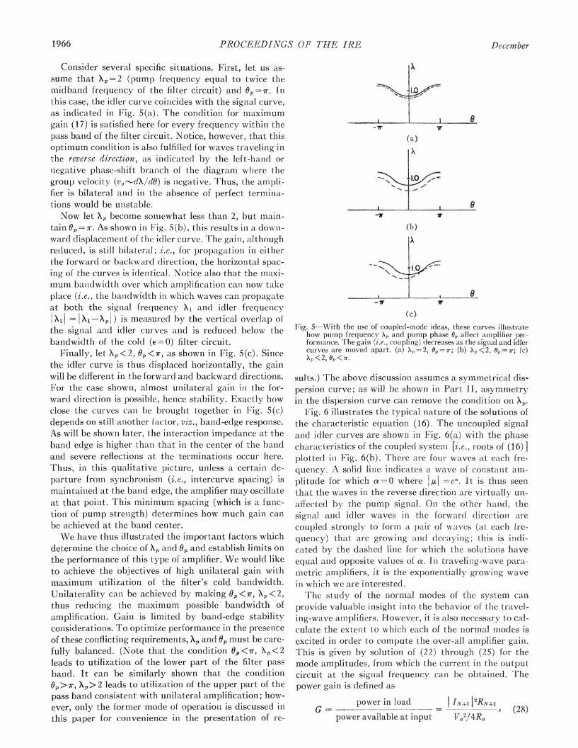
Consider several specific situations. First, let us as-sume that XP 2 (pump frequenicy equal to twice themidband frequency of the filter circuit) and 0=7r.i [this case, the idler curve coincides with the signal curve,as indicated in Fig. 5(a). The condition for mr-aximumgain (17) is satisfied here for every frequency withini thepass band of the filter circuit. Notice, however, that thisoptimum condition is also fulfilled for waves traveling inithe reverse direction, as inidicated by the left-hand ornlegative phase-shift branch of the diagram wheire thegroup velocity (v,f-dX1d6) is n-egative. Thus, the amplifier is bilateral and ini the absence of perfect termitna-tions would be unstable.Now let X, become somewhat less than 2, but main
tain -i=r. As shown in Fig. 5(b), this results in a downward displacemenit of the idler curve. The gain, althoughreduced, is still bilateral; i.e., for propagation in eitherthe forward or backward direction, the horizontal spacing of the curves is identical. Notice also that the maxi-num bandwidth over which amplification cani -ow takeplace (i.e., the bandwidth in which waves can, propagateat both the signlal frequeincy XI and idlei frequencyX21 = iXI pj ) is measured by the vertical overlap of
the signal and idler curves and is reduced below thebandwidth of the cold (e -O) filter circuit.
Fitnally, let Xp<2, 6p<7r, as shown in Fig. 5(c). Sincethe idler curve is thus displaced horizontally, the gainwill be differenit in the forward and backward diirections.For the case showii, almost unilateral gain in the for-ward directioni is possible, hence stability. Exactly howclose the curves can be brought together in Fig. 5(c)depenids on still aniother factor, viz., band-edge response.As will be showin later, the initeraction- impedance at theband edge is higher tlhani that in the centei of the bandand severe reflections at the terminations occur here.Thus, in this qualitative picture, unless a certaiLn de-parture fromn synchronism (i.e., intercurve spacing) ismainitainied at the bauid edge, the atnplifier may oscillateat that poinlt. This minimum spacing (which is a func-tioii of pump strenigth) determines how much gairi canbe achieved at the batnd center.We have thus illustrated the important factors which
determine the choice of X, and 0, and establish limits onthe perfornmance of this type of amplifier We would liketo achieve the objectives of high un-ilateral gain withmaximum utilization of the filter's cold bandwidth.Unilaterality can be achieved by making 6, < r, X < 2,thus reducing the maximum possible bandwidth ofamplification. Gain is limited by bau-d-edge stabilityconsiderations. To optimize performance in the presenceof these conflicting requirements, X, and 6, must be care-fully balanced. (Note that the condition b1<7r, X,<2leads to utilization of the lower part of the filter passband. It cani be similarly shown that the condition-6p> r, X,> 2 leads to utilization of the upper part of thepass band consistent with unilateral amplification; how-ever, only the former mode of operation is discussed iithis paper for convenience in the presentation of re-
-'V
(b)
-_ -Lwr
8
(c)F ig. 5-With the use of coupled-mode ideas, these curves illustrate
how pumnp frequency X,) and pumnp phase Op affect anmplifier per-formance. The gain (i.e., coupling) decreases as the signal and idlei-cuirves are moved apart (a) X,=2, Q,r, (b) X,<2 0,O=r; (c)X\<2, Op<W.
sults.) The above discussioii assumes a symmetrical dis-persion curve; as will be shown in Part 11, asymmetryin the dispersion curve can remove the conditioni oni X,
Fig. 6 illustrates the typical nature of the solutions ofthe characteristic equation (16). The unicoupled signaland idler curves are showtn int Fig. 6(a) with the phasecharacteristics of the coupled systeni [i.e., roots of (16)lplotted in Fig. 6(b). There are four waves at each fre-quency. A solid line indicates a wave of constanit amtplitule for which a=0 where JAI =e. It is thus seenthat the waves in the reverse direction aie virtually uniaffected by the puMp signal. On the other hanid, thesignal and idler waves in the forward direct-ion arecoutpled strongly to form a pair of waves (at each fre-quency) that are growing anid decaying this is indi-cated by the dashed linle for which the solutionis haveequal aiid opposite values of a. In traveling-w ave para-metric amp:lifiers, it is the exponentially growin-g wavein which we are interested.
Trhe study of the normal modes of the system canprovide valuable insight into the behavior of the travel-ing-wave amplifiers. However, it is also necessary t(o calculate the extent to which each of the normal modes isexcited in order to compute the over-all amplifier gaini.This is given by solution of (22) through (25) for themode amplitudes, from whiclh tlhe cuirrent in the outputcircuit at the signal frequen-cy can be obtained. Thepower gain is defined as
power in load IINR+v2RN+G =7- (28)
power available at input V02/4R0
1.966 D"e;emnber
.e

Currie and Gould: Coupled-Cavity Traveling-Wave Parametric Amplifiers: Part I-Analysis
-W
Uncoupled Signal and Idler Modes(a)
11
Coupled System: Roots of Determinantal Equation(b)
Fig. 6-Nature of the solutions of the determinantal equation. Thesignal and idler modes in the upper diagram are coupled by thepump as shown in the lower diagram. Solid lines indicate wavesof constant amplitude; dashed lines indicate a conjugate pair ofgrowing and decaying waves.
or, in terms of our normalized parameters,
G-4 | IN+1,|I2RORN+1, (29)
with the input voltage VO normalized to unity. In thisformulation, the gain includes the effect of reflectionsfrom both input and output terminations.
In Figs. 7-9 (next page), we have presented calculatedcurves of gain vs frequency. These curves are not in-tended to represent optimized performance; rather, theyhave been chosen to illustrate typical effects of varyingthe principal parameters pump frequency Xi, pumpphase shift between sections Op, and pump strength e.
For convenience, the fractional bandwidth of the coldfilter circuit has been chosen to be 10 per cent (k==0.05).As shown in Appendix I, these results can be scaled toother bandwidths by simple scaling rules. The loss fac-tor q is 0.002, corresponding to a cold insertion loss thatis approximately 0.2 db at midband and rising to about4 db per section in the neighborhood of the band edges.This corresponds roughly to the values measured in ex-
perimental models. The calculations are for a six-sec-tion amplifier; extensions to other numbers of activeelements will be considered later.
Fig. 7 illustrates the effects of varying pump fre-quency X, while maintaining pump phase and ampli-tude e constant at the values 2.85 radians and 0.033,
respectively. The curves are seen to be approximatelysymmetrical about the degenerate frequency X,/2. AsX, is reduced, several things occur: midband gain de-creases, bandwidth decreases, and ripples in gain aresmaller, particularly at the band edges.
This behavior follows immediately from our previousdiscussion. The present situation qualitatively resemblesthat shown in Fig. 5(c) or Fig. 6(a). As X, decreases, theidler curve is displaced vertically downward from thesignal curve. The maximum bandwidth over which bothsignal and idler frequencies can propagate is thus re-duced. In this case, a maximum utilization of about 80per cent of the total bandwidth of the filter circuit isshown for Xp= 1.97. Also, with decreasing Xp, the sepa-ration between signal and idler curves increases; i.e., thesignal and idler wave velocities depart more and morefrom synchronism, resulting in smaller midband gain.Similarly, the gain ripples are reduced in magnitude, be-cause of a reduced gain in the backward direction, whichmakes the amplifier less sensitive to reflections at theoutput termination, and because, at the lower cutofffrequency, the departure from the synchronous condi-tion begins to exceed the value above which signal andidler waves are essentially uncoupled.At reasonably high gains, the Manley-Rowe rela-
tions12 show that in the absence of loss, the amount ofoutput power at the signal and idler frequencies is aboutequal. Therefore, the signal and idler waves essentiallyinterchange roles as the signal passes through the de-generate point and the response is more or less sym-metrical about the half-pump frequency. Over-all band-width cannot exceed twice the difference between X,/2and the nearer filter cutoff frequency.
Fig. 8 shows the effect of varying the pump phaseshift. In terms of the Brillouin diagram, increasing 0,corresponds to displacing the idler curve horizontally tothe right. In this case, the bandwidth remains approxi-mately constant (i.e., the normalized degenerate fre-quency is fixed at 0.98). For smaller values of Of,, inwhich midband synchronism is most nearly approached,the general gain level is the highest, although with largevariations across the band in this particular case becauseof poor amplifier terminations.
Finally, in Fig. 9 it is seen that increased pump powerresults in larger gain, as expected, and also in a slightlyenhanced bandwidth. The latter is due to the fact thatthe reduction in signal-idler coupling in the vicinity ofthe band edge, which results from departure from syn-chronism, is compensated by increased capacitance vari-ation (i.e., pump power).Although the terminations can be greatly improved
so as to smooth out the gain peaks (see below), theband edge poses a special problem. This can be seen byintroducing the concept of an "interaction impedance,"which measures the quality of a particular coupled-cavity circuit design. Letting P represent the averagepower flow associated with a peak voltage V,, across thelocalized capacitance of the nth cavity (loaded by a
-~~~~ly
19671960

PROCEEDINGS OF THE1 IRE
20
0 _-
1050.95 1.O
NORMALIZED FREQUENCY X
Fig. 7-Gain vs frequency for a six-section amplifier, showing theeffect of varying pump frequency X,. A filter bandwidth of 10 percent was chosen for convenience
20
.0
z
(9
CD
k=.05
Xp=1.96e6.035
1 q-.002
0 _
0
0.95NORMALIZED
1.051.0FREQUENCY X
Fig. 8-Gain vs frequency for a six-sectioni auniplifier, showiig theeffect of varyinig puminp phase 0.
variable capacitaiuce diode), ve (define the initerac tioni
impedanice to be
(30)K
2IP
It is shown iii Appendix II that this in-teractioni iimnped-anice is a fuinclamenital paramieter in all capacitively
pumped, traveling-wave parametric arnplifiers andshould be maximizecl for strong coupling between- thesignial and pump frequencies at the diode junction. Thisalso is iin agreement with the intuitive ilea that for a
given power flow the signal voltage shoulld be maxi=mizecl across the variable capacitance. A similar pa-
rameter is important in' the designi of travelinigrwavetubes. Foi the cold circuit ( 0),
Re [j ,in*
which can be expressed iii terms of voltage as
= aAIC2 V" |12 sin 0
u,ing Vi V,,eiA Therefore, neglecting loss,
(31)
(32)
(33)vI /C1
X6k sin 0
Additional physical interpretatioi of interactio im-
pedance can be obtained by expressing power flow iithe form
P WV,, (34)
kc.05fepP 2.85
= 033
5
O
25
20
z 10
(5
5
0
XP/2
0.95 1.0NORMALIZED FREQUENCY X
Fig. 9-Effect of increasing pump amplitude e.
.W-
--,..I I I ]L--
1968 .Decembler
5 ~
I I |
I
I

190 Currie and Gould: Coupled-Cavity Traveling-Wave Parametric Amplifiers: Part I-Analysis
where W is the total time average stored energy percavity (half in the electric field, half in the magnetic)for a peak voltage V,,,
W = .Co I Vn I2, (35)
and v, is the group velocity,
Oo I1vg = - = V'C X3k sin 0 cavities/second. (36)
Eq. (13) was employed in arriving at (36). Substituting(35) and (36) into the definition of interaction imped-ance, we again arrive at (33). High impedance restultsfrom minimizing electric-energy storage (i.e., decreasingtotal capacitance Co or physically concentrating all ofthe electric field at the position of the variable capaci-tance) and by decreasing the group velocity. The formeris a function of the basic cavity design, and the latter iscontrolled by adjusting the coupling between cavities.
In the vicinity of the lower and upper band-edge fre-quencies, 0 approaches 0 and 7r, respectively, leading toextremely high values of interaction impedance. Thisresults physically from extremely low group velocity.We then have a situation in which the cavities behavesomewhat like individual single-cavity amplifiers withcoupling predominantly by means of the idler wave.Thus, for example, the gain at midband, which can beattained by increasing the pump amplitude to higherand higher values, is ultimately limited by incipientband-edge instability.
Eq. (33) also indicates that at midband (X_1, sin0-1), the product of interaction impedance and band-width (k) is approximately constant. This is related tothe bandwidth scaling considerations of Appendix I andis a fundamental result. Since interaction impedance isa measure of gain per section, a basic inverse relation-ship exists between bandwidth and gain per diode. Ananalogous impedance-bandwidth relationship obtains inthe case of traveling-wave tubes.13The philosophy that was used in determining the in-
put and output impedance matches was to use a simple,physically realizable impedance function with only threeadjustable constants. In particular, normalized gener-ator and load impedance functions of the following formwere employed:
ZO= Ro+jXo = C1+j(C2X + I
In all of the curves presented thus far, both Z' andN+1 were chosen so as to constitute a match to the cold
filter circuit at midband only; i.e., the normalized inputimpedance of the coupled cavity circuit is
Zi = Xk sin 0 + jXk cos 0, (39)where 0 is the phase shift per section and circuit loss hasbeen neglected. The resistive and reactive parts of (39)are shown by the solid lines in Fig. 10(a). In the calcu-lations corresponding to Figs. 7 through 9, the constantsC] . * C6 were chosen so that the real part of the gen-erator and load impedances exactly matched the re-sistive part of the cold-circuit impedance only at thecenter of the pass band (X = 1, ==7r/2). The reactive partwas chosen to be zero at midband and to have an ap-proximate conjugate slope to that of the reactance func-tion in (39); i.e., for Figs. 7 through 9, C . C6 wereadjusted so that
Ro RN+1 k,O 0
X = XN±l - - Xk cos 6. (40)
These relations are indicated by the dashed curves inFig. 10(a). The approximate reactive compensation canbe effected physically by simply placing a series reso-nant circuit in series with the transmission line.The large fluctuations in the gain curves indicate that
the above choice of generator and load impedances givesrise to large reflections. Indeed, it is intuitively evidentthat, at the output, we want to establish a match to theexponentially growing wave. The appropriate output
.05
-.05'
(37)
ZN+1 = RN+1 + jXN+1 = C4 + i (CAX+--) (38)
corresponding to a series resistor, inductor, and capaci-tor.
13 J. R. Pierce, "Traveling-Wave Tubes," D. Van Nostrand Co.,Inc., New York, N. Y., Chap. V; 1950.
XRo
- \/ <//~~e k=.05
/ RI- ,F PASS` d\AND --_
/ \
(a)
(b)Fig. 10-The solid curves show the resistance and reactance of: (a)
cold circuit iniput impedance Z? =Xk sin O+jXk cos 0; (b) grow-ing wave impedance Z:,=jXk/,ut. In Figs. 7 through 9, the gen-erator and load impedances were both chosen as indicated by thedashed curves in (a) above; in Fig. 11, the output was matched tothe growing wave at two frequencies as indicated by the dashedcurves in (b).
19691960

1970 PROCEEDINGS OF THE ITRDE
impedanice is then
Z,0ut k (41)
wlhere A, is the particular root of the characteristicequation (16) associated with the growing wave. Theimpedance level at tlhe output is thus reduced belowthe iniput level by essentially the voltage gain per cav-ity. A plot of (41) for a typical case is showxn in: Fig.I0(b).The effect of matching to the growing wave at the
output is shown in Fig. 11. With the generator and loadimpedances matched to the cold circuit [i.e., as in, (40)j,the curve with large midband gain fluctuations and extremely high peaks at the band edge is obtained; this isthe same as one of the curves in Fig. 9. With the outputapproximately matched to the growinig wave [as indi-cated by the dashed curves iii Fig. 10(b)] a greatlysmoothed-out response curve iesults.
Thus, in the abseiice of stabilizing nonreciprocal atteniuationi the amplifier response is relatively seiisitive toterminatinig impedances. It is, of course, possible to im-prove further the results of Fig. 11. Here, the resistivepart of the output growinig-wave impedalice is matchedexactly at only two frequencies, as in1dicate(l by themagnitude of RN+3 in Fig 10(b). The use of more com-
plicated inipedance functionis could niake t-he curve otgain vs frequenicy almost flat. This has beerideihnoiistrated experimein-tallv.
'Iiclu(lced in1-Fig. 1 is a curve of reverse gain. Hlere,the input and output terminals of the amplifier weresimply interchanged with the same matching (coiditioinsas those described above It is seen that the reverse gainicani be maintainied at a value in the neighborhood ofun-ity with 12 to 15-db gaiii ii the foriwart di(rection,esseiitially uanilateral anplificationl Crail therefore lbeachieved.Midband gaiii is plotted in FSig. 12 as a fuiictioni of the
number of iterative cavity sectionis for a particularchoice of parameters. The dashed curve represents thelevel of the expoiientially irlcreasing wave alonr, thihswave predomiiiates after several cavity sections Noticethat an initial excitationi loss of about I db (an1 be associated with the growinig wave for the c ase showiii :Inthe case of perfect synlchronism between the sigiial andidler waves [i.e. if the phase relatiotn in (I 7) is sttisfiedllthe growing anid decavinig waves are excited in phase,each havinig associated with it the applied voltagePIhis would lead to an iitial growiig-wave Ioss of 6 dbWith inicreased departure from syrichroniism, hiowever,the initial amplitudes of the growitig aiid dlecayingwaves iiicrease (they are no longer excitedI in phase)
29.3 db 31;5db__ _ __ _ __ _ _ __ _ __ _ __ _
-III11IIIlj
i III
10 kx.05-I GP6 2.9p1zpa1.96I I £w.038
II
IE
I
'ECf
\
\~~~~~~~~~~~~~~xp/p,
0.95 1.0
NORMALIZED FREQUENCY A
14 _ k-=.051 p4 2.9
XP ct1.962 - c =
-.0325g%=.002
101~
'U
z
0;
2
I INITIAL LOSSi.05 OF
GROWINGWAVE
Fig. 11-Effect of matching to the growing wave. The solid gainl curvewas calculated for an output terminal impedance as showni inFig. 10(b), which resnlited in a smoothed-out frequency responseand great reduction in band-edge gain spikes. The extremely lowreverse gain shows that unilateral amplification is possible.
CAVITY 1.5db
GROWING WAVE
2 4 6 8 (
NUMBER OF CAVITY SECTIONS
F ig. 12- Gain vs the number of iterated cavity sectioins as calcltatetifor a particular case. The initial excitation loss of the exponleti-tially growing wave is shown.
20h
151-
lO -
z:
5
o
1970 Decemnber
8
4 1
-21

Cutrrie and Gould: Coupled-Cavity Traveling-Wave Parametric Amplifiers: Part I-Analysis
and the initial loss factor of the growing wave decreases,approaching 0 db.The above behavior is, again, entirely analogous to
that of traveling-wave tubes and is, in fact, basic to allactive coupled-mode systems. In the traveling-wave-tube case, there are three characteristic waves (growing,decaying, andl unattenuated). With exact synchronismbetween the electron beam waves and the unperturbedcircuit wave, each of the characteristic waves is excitedin phase with 3 of the applied voltage, leading to an
initial growing-wave loss of 9.54 db. This initial loss de-creases with departure from synchronism of the unper-turbed coupled modes.14
Parameter studies of the type described in this sectionshow that the effect of increased circuit loss is twofold;the midband gain is decreased and the response curve issmoothed out, particularly at the band edges. The low-ered gain can be made up simply by increasing thepump voltage. It should be noted that the maximumvalue of iAC/C0 employed in the calculated results pre-sented in this paper is less than 0.16, corresponding to a
value of e of 0.04 [see (27) ]. Considerably larger capaci-tance swings are possible and have been achieved experi-mentally. The improved band-edge response resultsboth from reducing the regenerative effects of reflectionswhere the impedance mismatch is worst and from lower-ing the Q of the individual cavities in the narrow, band-edge mode of operation. Thus, the response curve ofFig. 11 cani be smoothed out still further by the combi-nation of better matching and slight additional circuitloss, although the latter would deteriorate the amplifiernoise figure somewhat.
CONCLUSIONA class of traveling-wave parametric amplifiers based
on coupled-cavity filter circuits has been described. Thistype of amplifier is particularly suited to microwave fre-quencies and incorporates new features that overcome
some severe difficulties associated with other circuitstructures. An analysis has been presented which notonly provides detailed information on the operatingcharacteristics of such amplifiers, including the effectsof terminal impedances, reflected waves, circuit loss,etc., but also leads to a simple physical picture of thecumulative interaction mechanism based on thecoupled-mode concept. This physical picture, presentedin terms of a Brillouin diagram, has been emphasizedthroughout. Fundamental gain and bandwidth consid-erations have been discussed in terms of an interactionimpedance parameter, which is basic to all amplifiers ofthe traveling-wave type.
Representative calculated curves of gain vs frequencyhave illustrated the general effects of the various pa-
14 C. K. Birdsall and G. R. Brewer, "Traveling-wave tube char-acteristics for finite values of C," IRE TRANS. ON ELECTRON DEVICES,vol. ED-1, pp. 1-11; August, 1954.
rameters; these effects have been related to the quali-tative description of the amplifier. The calculationshave, of course, explored only a restricted range of pa-rameters, but they indicate typical results and, moreimportant, serve as a guide to experimental optimiza-tion of pump frequency and phase, terminal imped-ances, pump strength, etc.From this investigation, we conclude that unilateral
amplification can be obtained over an appreciable por-tion of the pass band of the coupled-cavity circuit.Stable gains of 12 to 15 db are possible with reasonablyflat frequency response. With special stabilization, op-eration much closer to the ideal synchronous conditionwould be possible with resulting higher gain per stage.Such stabilization can be obtained, for example, by in-corporating nonreciprocal ferrite elements in thecoupled-cavity circuit itself or by cascading two ormore amplifier sections separated by ferrite isolatorsand correctly phased with respect to pump voltage.Techniques such as staggered pass band edges and non-uniform phase shift between cavities, which haveproved very important in solving various stability prob-lems in traveling-wave tubes, can also be used to ad-vantage; however, these possibilities are not providedin the present analytical approach.
It is not yet known how far bandwidth can be pushedwith coupled-cavity amplifiers. Certainly fractionalbandwidths of 20 to 30 per cent appear to be possible.As bandwidth increases (i.e., for larger values of thecoupling coefficient k), the Brillouin diagram becomesdistorted appreciably from its approximately sym-metrical shape at the low values of k, and the band-width scaling rules presented in Appendix I must bemodified. This is an important area for further investi-gation, and can be most easily accomplished experi-mentally with the analysis serving as a general guide,as discussed in Part II.Another area for further study consists of allowing
the idler frequency to be several times larger than thesignal frequency and to propagate in a separate coupled-cavity circuit (or perhaps in a higher pass band). TIhisis important in reducing the noise contribution of theidler channel. With appropriate interpretation, thepresent theoretical approach can be made to includethis situation.Although noise considerations have not been included
explicitly in this treatment, it is shown in Appendix IIthat over any small frequency region this analysis canbe related in simple terms to analyses based on anidealized uniformly distributed model. Therefore, atleast to first order, noise performance can be estimatedby Tien's results as modified by Shafer"5 for the case offinite circuit loss.
15 C. G. Shafer, "Noise figure for a traveling wave parametric am-plifier of the coupled-mode type," PROC. IRE, vol. 47, p. 217; De-cember, 1959.
19711960
PROCFEDINGS OF TIIE IRE
APPENDIX I
BANDWIDTH SCALINGThroughout the text we have, for convenience, takeni
k=0.05, leading to a 10 per cent cold bandwidth of thefilter circuit. We show here that these results cani begeneralized to other values of k ancd hence to other band-widths. The scaling conisiderations presented here as-sume k to be small compared witlh unity. F or largerbandwidths, these scaling rules provide at least an ap-proximate guide to the choice of parameters and to theexpected performance.To obtain the basic result, we initroduce variables 8
and 4p, respectivelv:
X1 1 Ik+ y Xv=2 + k8; (42,
8 varies from -1 to +1 as X varies from the low-fre-quency cutoff
1
V\-+ 2j kjI ~- k
equation (16) must vanish separately:x,2[1 + 2k cos 01 = IS
X22[ + 2k cos (02 0)1 I (44)Hiere we have taken I e j0 and used the subscripts Iand 2 for quantities pertaininig to the sigiial and idlerfrequencies, respectively.
For optimum gain in the presence of the pump, wehave shown- that 01 and 02 should be approximatelyequal. We therefore write 02 =0,+AO, where AO isassumed to be small. Substitutifig e--A foi A with0 =1+A6/2-jrP 02-A6/2-jP (1 small) into (16) anidusing the definitionis of 06 amd 02 in (44) above, we ob-tain an approximate equation for I' the growt:h cO1i,stant:
where
(45)
(46)k2X12X22 sin 61 sin (0, 02)
to the high frequency cutoff
X ut f A21t.kk
Substituting the above definitionis into the determi-nantal equation- (16), we may write
[2 + i + - -q][2(6 - 61) - lie + _ kl
2
We see that the values of ,I, anrd hence the gain perresonator, depend only upon the variables, 6, 85, 0p,q/k, and e/k. Thus, two amplifiers with different banid-widths (different k values) will have exactly the samegain vs reduced frequency 8=(X1-1)/k if they havethe same values of bp, G,, q/k, add e/k. In particLular,the circuit with the larger bandwidth will requjire alarger value of the pump parameter e, larger in the ratioof the bandwidths, for the same gain.
This result has been verified by computing gain vsfrequency for circuits with different values of k butwith identical p,, OP, q/k, and e/k. The result is accuratein detail for small values of k; when k becomes as largeas 0(1, some minior quantitative difference arises.
This has the same form as lien's equation (41), exceptthat our quantities F, (, and AG are expressed oni a percavity basis and Tien's are referred to a un-it lenigth.From (45) and (46), the gain at midbaiid for A= 0 isessentially (c/k) nepers per cavity, which again enphasizes the reciprocal relationship between gaini andbandwidth (k).To bring out further the analogy with T'ien's result,
we can rewrite our result in terms of the iinteractinwi impedance defirned earlier [see (30)]. The interaction imyipedances at signal and idler frequencies are
713L;COX23k sin 6
K2\I/CO
X21k sin (0p 02)(47)
and are equal to the square of the voltage appeariingacross the pump element per uiiit power flow at signialand idler frequencies, respectively. Iherefore, 2 maybe writteii
2 KIK2WIC20C7 (48)
where 6/Co =-/SoK<1 is the fractional chanige in ca-pacitance. We see that our result is the product of theinteraction impedances K1 and K2 and the variableparts of the susceptances wXC and wj. The gain isclearly increased by -increasing any of these quanitities.
Tien's expression for 02, applicable in the case of in-ductive pumping, can be expressed
Y2-oIYo2WLW2L,APPENDIX II
RELATION TO TIEN'S RESULT
We show here that when the gain per sectioin is smalland there is no circuit loss, (16) can be cast in the sameform as Tien's result for a uniformly distributed trans-mission line. First we note that in the absence of thepump (c-0), each of the brackets of the determinantal
(49)where Yo1 and Yo2 are the "interaction admittances` atthe siginal and idler frequencies, respectively, niuner-ically equal to the square of the current flowing throughthe pump element per unit power flow (Yo, =12/2P,),anrd co,L and W2L are the variable parts of the reactatncesadded by the pump. In fien s case, maximum gain isachieved by maximizing any of these quantities; in par-
1 972 Diecember
1960 Grabowski and Weglein: Coupled-Cavity Traveling-Wave Parametric Amplifiers: Part II-Experiments 1973
ticular, the current flow through the pumped elementshould be a maximum. Note that for the uniform modelconsidered by Tien, the interaction admittance and thecircuit characteristic admittance are equal. The former,however, is a more fundamental parameter in traveling-wave parametric amplifiers. Tien's inductive pumpingis the dual of our capacitive pumping, and this fact re-flects itself in the dual nature of the expressions for 02.
ACKNOWLEDGMENTThe authors gratefully acknowledge many fruitful
discussions with R. D. Weglein and K. P. Grabowskiof the Electron Dynamics Department, who contributedgreatly to this investigation and carried out the associ-ated experimental program. Thanks are also due B.Fik, who carried out the programming and numericalcalculations on an IBM 704 digital computer.
Coupled-Cavity Traveling-Wave ParametricAmplifiers: Part 11-Experiments*
K. P. GRABOWSKIt, MEMBER, IRE, AND R. D. WEGLEINt, SENIOR MEMBER, IRE
Summary-The filter-circuit approach to broadband traveling-wave parametric amplification at microwave frequencies is describedfrom an experimental point of view. The experiment revolves arounda series of inductively coupled microwave cavities, each loaded withone variable-capacitance semiconductor diode. Gain-bandwidthproducts of 2000 Mc with a 350-Mc bandwidth at S band have beenobtained by using commercially available diodes. Noise tempera-tures of 1300 K have been measured.
Based on the analysis of the companion paper, a qualitative pre-diction of the gain-frequency behavior is given. The experimental ar-rangement is set forth in some detail. It consists of a series of thesecoupled cavities with separate pump power distribution at each diode.Through this flexibility in pump phase shift and amplitude, a varietyof advantages is achieved. The effects of the many variables on theperformance of the amplifier are described.
Several methods of achieving short-circuit stability of this am-plifier are outlined. These are: 1) nonuniform pump phase shift be-tween sections, 2) nonreciprocal loss with ferrites, and 3) nonrecipro-cal loss with upper pass bands. The experimental behavior of eachmethod is shown, and the noise performance to date is briefly dis-cussed.
INTRODUCTION
pARAMETRIC amplification is the result of constructive mixing of a small signal and a largesignal (pump) in a nonlinear reactance. This prin-
ciple was successfully demonstrated by Hines,' whofirst employed the voltage-dependent capacitance of areverse-biased semiconductor diode for this purpose.Since then the principle has been much discussed andapplied, and thus the familiar cavity parametric am-plifier has evolved. Three frequencies, signal, idler, and
* Received by the IRE, May 5, 1960; revised manuscript receivedAugust 19, 1960.
t Hughes Res. Labs., A Division of Hughes Aircraft Co., Malibu,Calif.
I M. E. Hines, "Amplification in Nonlinear Reactances Modula-tors," presented at the 15th Annual Conf. on Electron Tube Res.,Berkeley, Calif.; June, 1957.
pump, are generally of interest in this device, each ofwhich is usually supported in a resonant circuit or cav-ity and all are coupled to each other through the non-linear behavior of the diode capacitor. The high im-pedance of the resonant circuit at each frequency re-sults in maximum utilization of the signal power to beamplified and in a minimum requirement of pump powerfor a given capacitance swing. Further consequences ofthe use of resonant circuits are restricted bandwidthand an approximately constant voltage gain-bandwidthproduct. Finally, because of its negative resistancecharacter, a circulator is required in the amplifier tomake it unilateral and stable.When a series of these cavity-type amplifiers are
properly cascaded, traveling-wave parametric amplifi-cation in a filter circuit results. The undesirable featuresof restricted bandwidth and regeneration largely giveway to increased bandwidth and unilateral gain withoutthe use of a circulator, while the advantages of lownoise, high gain per diode, and low pump power are re-tained. The increase in bandwidth is a consequence oflarge coupling between individual cavities, resulting ina filter-circuit response. Unilateral gain is obtained byproperly adjusting the relative phase shift betweencavities at the pump frequency. High gain per stage(i.e., per diode) and low pump power are intimately re-lated to the high impedance level of the filter circuit.Additional advantages of this circuit at microwave fre-quencies are large physical separation of diodes, flexi-bility in control of higher pass bands, and the ease withwhich nonreciprocal loss may be incorporated to en-hance unilateral gain stability.
It is the object of this paper to describe in detail thefilter-circuit approach to traveling-wave parametricamplification, from the experimental point of view, and