costing of pipelines
DESCRIPTION
Guideline on pipelines costing, comprehensive details for piping cost estimation.TRANSCRIPT

Costing of Pipelines - 1
1. Introduction
• The selection of the optimal pipeline route, diameter, material, wall thickness, pump
station location, pump units and operational equipment or facilities is typically the result of
economic analysis and investment capital evaluation of the most reasonable scenarios
developed through
the design phase.
• Typically, even before the detailed design of a pipeline system has begun, an order-of-
magnitude cost study will be performed, with the goal of determining the feasibility of
continuing to invest time and capital in the design phase of the project.
• For a typical cross country pipeline project, the cost of pipe and its
associated construction and installation costs can be as much as 80% of
the capital investment , therefore , the selection of the pipe, with regard
to the type of material, size etc. is very important.
• A piping works engineer requires not only wide engineering knowledge
– not necessarily in depth , but certainly an understanding but he must
also have an understanding of engineering economics, costs of
metallurgical, methods of pipe fabrication, erection and sufficient
knowledge of mechanical, civil, electrical and instrumentation
engineering to discuss the requirements.
2. Direct and Indirect Costs Associated with Piping
• The direct cost of piping is related to the purchase and installation of
piping along with accessories. i.e. it deals with raw materials, labour,
energy etc.
• Indirect cost includes:
• Design and engineering cost, which cover the cost of design and cost of
“engineering” of the piping system, purchasing, procurement and
construction supervision.
• Contractor‘s fees (Technology Fee)

• Contingency allowance, this is an allowance to cover for unforeseen
circumstances ( labour disputes, design errors etc.).
3. Economic Evaluation of the Piping System
• As the purpose of investing money in modern piping system is to earn
money, some means of comparing the economic performance of piping
is needed.
• For a small piping system , and for simple choices between alternative
processing schemes , the decisions can usually be made by comparing
the capital and operating costs. More sophisticated evaluation
techniques and economic criteria are needed when decisions have to be
made between large, complex piping systems, particularly when the
piping systems differ widely in scope, time scale, etc.
• Making major investment decisions in the face of uncertainties that
will undoubtedly exist about plant performance, costs, the market
Government policy and the world economic situation, is a difficult and
complex task (if not an impossible task) and in a large design
organisation, the evaluation would be done by a specialist group.
4. Economics of Pipe Diameter – Concept
• The sizing of process lines can be divided into two categories
Lines which do not contain pumping equipment
Lines which contain pumps or compressors
Lines in the first group are sized on the basis of available pressure drop,
while those in the second must be based on an economical pipe size ( the
smaller the pipe , the less the pipe costs but the higher the pumping costs, and thus an
optimum size must exist).
Paradoxically, however, it is uneconomical to make economic studies on each process line
for a proposed plant. The designer, therefore, must have some means of determining which
lines justify careful cost analysis.

The designer can select a conservative line size which will definitely fulfill the requirements.
But will the next smaller size be more economical? The only manner in which this can be
determined definitely is by careful economic analysis.
If the possible saving , however, is not far from the cost in the man-hours required to make
the study, it is better to select the conservative size without further use of valuable time.
If, on the other hand, the possible savings are substantial, then further detailed study is
indicated.
5. Inch Meter and Inch Diameter Concept
Purpose:
The purpose of inch meter and inch diameter is :
a. To find out piping erection load
b. Manpower planning
c. Piping work progress monitoring
d. Costing
The following example will illustrate the concept of the inch-meter and the inch-dia:
Q.1 Elbow 2" size, 20 nos., are to be fitted in a pipeline. Find out the inch dia?
Ans: Inch dia : size x no. of weld joints x no. of elbows
= 2 x 2 x 20 = 80 inch dia.
Q. 2 Find out the inch meter for 20 m pipeline of 2" size
Ans: Inch meter = Pipe size in inches x length in m
= 2" x 20 = 40 inch meter
Note : Inch meter will be more relevant in case of yard piping whereas inch dia will be more
relevant in case of plant piping.
6. Dividing the Cost of the Pipe Work
The costs of process industry pipe work are usually sub-divided as below:

1. Piping design and engineering: The cost of design work associated
with the pipe work including layout studies , scheming , analysis and
detailing.
2. Materials: The cost of all bought out materials , i.e. pipe flanges, fittings, valves,
expansion units, etc.
3. Fabrication: The cost of site fabrication , off-site fabrication, done in a
shop away and adjacent to site.
4. Erection: The cost of erecting on-site fabricated pipe work and pressure testing. This
includes preliminaries, variation orders and error
rectification if any.
Economic
Fluid Velocity (ft/s)
Pipe diameter d (in)
Pressure drop
available
(Ib/in2) / 100 ft
Remark
Pump discharge pipe
(d/3 + 5) ft/s 2.0
Pump suction pipe
(d/6 + 1.3) ft/s 0.4
Steam or gas line
20 d ft/s 0.5
For liquids, a velocity in excess of 20 ft/s should never be specified in order to avoid erosion
of the pipe. On suction lines to the pump, the pressure drop should always be less than 50%
of the total head developed by the pump.
7. Suggested Steam Pipe Velocities in Pipe Connecting Steam Turbines
SERVICE - STEAM TYPICAL RANGE -ft/s
Inlet to turbine 100 - 150
Exhaust, non-condensing 175 - 200
Exhaust - condensing 400 – 500

8. Relative Economics of Various Materials of Construction
S.No. Material Connection Factor
1 Carbon steel (C.S.), A-53,
seamless Welded 1.00
2 Carbon steel (C.S.), A-53,
welded galvanised Screwed 0.84
3 Wrought iron, galvanised Screwed 1.61
4 Unplasticised polyvinyl
chloride Sock, weld 1.79
5 Carbon steel, lead lined Flanged 4.11
6 Carbon steel, PVC lined Flanged 4.76
7 Stainless steel Welded 15.00
9. Material Estimation
There are three main topics of pipe work estimation as mentioned below:
S.No. Stage Accuracy Basis
1 Preliminary +/- 25% Based on %age of total plant cost
2 First control +/- 20 % Based on completed P and I’s etc.
3 Second control +/- 10 % Final P and I, all pipe work details, drawings,
material list etc.
10. Fabrication Cost Estimation
The contents of fabrication cost estimation comprise the following:
1. Fabrication
2. Fabrication / Welding
3. Welding
4. Supports

11. Erection Cost Estimation
The contents of fabrication cost estimation comprise the following:
1. Erection
2. Supports
3. Testing of completed pipelines
12. Rates for Fabrication and Erection
The schedule of rates under the fabrication and erection work are established in “man
hours” which should be representative of the gang time to complete the operation. The type
of rate will depend on the client and contractor relationship on the basis of the contractor’s
tenders.
The rates shall be included or excluded, allowances for construction plant, tools, tackle and
consumables.
Typical rates for various piping materials are enclosed for reference. These include labour,
consumables, tools, tackles and overheads.
13. Typical Rates for Fabrication, Erection and Testing of Pipelines for
Costing with Example
a) Mild steel (MS), B and C class piping: Rs. 45/- per inch dia per metre
length.
b) SS 304 piping ( Sch 5): Rs. 90/- per inch dia per metre length.
c) PVC Piping: Rs.45/- per meter length.
d) Cu Piping: Rs. 100/- per inch dia metre.
e) Pipe fitting reducer, bend etc.
SS 304: Rs. 125/- per inch dia
MS: Rs. 60/- per inch dia
Copper: Rs.140/- per inch dia
f) Fabrication and erection of MS supports= Rs. 4500/- per MT.

Q. Find out the labour cost for making a MS reducer of 2" x 4" size?
Ans: MS Reducer 2" x 4" = 4x60 = Rs.240/- (Considering 4" dia)
Q. Find out the labour charges for fabrication and erection of a MS pipeline of 50 NB (2")
MS “B” or MS “C” of 400 m length fabrication and erection?
Ans: 2 x 400 x 45 = Rs.36,000/-
Typically the quantum of pipe fabrication, erection and testing of pipe work shall be
expressed as shown below:
1. MS “B” and “C” class piping : 12450 inch mtr
2. SS 304 piping : 2850 inch mtr
3. PVC piping : 285 inch mtr
4. Cu piping: 695 inch mtr
14. Typical Calculation for Piping Cost
Raw material
Factors SS Condensor
tube
Copper
Condensor tube
Sheet width mm
Raw material base
rate Rs/kg 78.50 140.00
Packing and
forwarding Rs/kg 1.00 0.79 1.40
Conversion Rs/kg 40.00 50.00
Excise % 16.00 19.09 30.62
Sales tax/ VAT % 4.00 5.53 8.88
Insurance % 0.20 0.29 0.46
Transportation Rs/kg 2.00 2.00
Total Cost Rs/kg 146.19 233.37

Modvat Benefit Rs/kg 19.09 30.62
Cost to Co. Rs/kg
127.11 202.74
Rs/mtr
93.81 246.74
15. General Scope of Work for Piping Fabrication and Erection
• Fabrication, cutting, welding, assembly in position as per drawing.
• All raw material i.e. pipe, reducers, bends, flanges, sockets etc. and
hardware i.e. nut, bolts, gaskets etc. shall be supplied by client.
• Fitment includes assembly of fittings i.e. flanges, bends, valves, reducer, fabrication of
tees, fitment of non return valve, valves, gaskets, nut bolts, sockets for pressure gauges
fabrication and fitment of thermowell, etc. Pipe work shall be carried out as per piping
drawings/ specifications/ instructions given to construction engineer.
• After assembly, complete pipeline to be welded by taking necessary
precautions to avoid stresses. If stresses developed , those are to be
removed and welded as per standard practice and instructions of the
site co-ordinator.
• One in-position weld is allowed for line which cannot be welded on
ground.
• After welding , finishing and grinding , pipeline to be hydraulically tested at pressure
specified in the order.
• After hydraulic testing, pipeline to be painted with red–oxide ( one coat).
• After painting, pipeline to be assembled in position and with necessary
clamps and supports.
16. List of Tools, Tackles and Machinery Required to Carry Out the Piping
Works
To be arranged by contractor:

1. Rectifier
2. H.F. unit
3. Transformer
4. Grinders- AG7
5. Winch – 5 MT
6. Chain block 3 MT 11 mtr. Lift
7. Ropes / pulleys
8. FF2 grinder
9. Hacksaw/Files etc. and other tools and tackles.
10. Pipe voice
11. G Q 4 Grinder
12. Abrasive cutting machine
13. Gas cutting
17. Contractor Manpower List of Piping, Fabrication and Erection
For piping, fabrication and erection:
1. Experienced Mechanical Engineer as in-charge
2. Supervisor
3. Highly skilled fitter for SS 304
4. Highly skilled fitter for MS B and C class piping and fabrication
5. Welders for SS TIG, Welders for SS Tacking, Welders for MS Tacking
6. Helpers/Riggers
18. Additional Cost Information
• Piping cost may vary between 20 to 66 %.
• Piping cost may be a headache to the estimator as he/she is asked to
give the cost even before engineering and execution.
• The estimator needs to convert the preliminary flow sheet into a fair
approximation of an actual design.
• The estimator should have the skill to draw quick and rather accurate
free hand isometric sketches, which will be of inestimable value.

19. Methods used for Estimation
• Piece by piece method ( Detailed costing)
• Finagling factor ( 40 % of equipment cost)
• N system.
20. N System
The N system is based on the fact which has been tested many times, that the costs of strings
of pipes of different sizes but of the same material and class of pipe bear constant relations
to each other. The N system was introduced by R.A. Dickson (Chem. Eng. Nov 1947, PP 121-
123)
21. How to use the N System
Step I : Calculate the cost of the reference sizes of the strings of pipe in question.
StepII : Then use the N factors to get the cost of the same string in the required size.
22. Piping Cost Estimation
Piping always represents a sizable part of the total installed cost of any process plant. It may
run to 20 percent or even more of the entire cost of the plant, including land and buildings,
and may total from around 10 percent to as high as two-thirds of the cost of the equipment.
But piping is usually complicated and often consists of a myriad of small, rather inexpensive
parts. Its estimation can therefore be a headache to the estimator.
It makes his problem no easier that he is often asked for a reasonable estimate long before
the final plans exist and before the project engineers have any idea how much piping will
actually be needed. In this case, he must not only be an estimator, but he must be able
quickly to convert the preliminary flow sheet into a fair approximation of an actual design to
know what his estimate will involve. For this purpose the ability to make quick and rather
accurate free-hand isometric sketches is of inestimable value.
However, the estimation of the piping need not be arduous if the estimator will make use of
the N system developed by the another during the last several years. This system, first
disclosed in Chemical Engineering (R.A. Dickson, Chem. Eng., November, 1947, pp 121-123)
has now been carried much further and includes most kinds of pipes with which the
chemical engineer is likely to be concerned.

The N System of Calculating Piping Costs. This new system of estimating
piping cost is quicker than the piece-by-piece, and more accurate than the “finagling-factor,”
system, the two methods ordinarily used by estimators.
The first requires picking of each length of pipe with its fittings and valves
and pricing the material and labour costs in detail, then adding them all up for the total
cost. The second consists in taking a percentage of the total cost of a project as the cost of
the piping. This percentage the “finagling factor,” is supposed to be around 40 percent.
* The author wishes to express his appreciation to the firms listed and to
may others who prefer to remain anonymous, but who helped by furnishing cost data on
which the N-factor tables are based. Specific acknowledgement is made to Armstrong Cork
Co., Inc.; Mundet Cork Corp.; Johns Manville, Inc.; Cooper Alloy Foundry Co.; Taylor Forge
and Pipe Works; Andrews Knapp Construction Co.; Knapp Mills Inc.; The Saran Lined Pipe
Co.; The Rie-Wil Co.; and The Duriron Co.
See, for example, Table 10-33 of the N factors. The costs of different sizes of steel Pipe, butt-
welded, schedule 40, black, with fittings and valves as specified, will be to each other
approximately as the N factors. As the table shows, a string of 2-in nominal diameter pipe
will cost 1.84 times as much as the same string in 1 in.
Take, for example, a string of such pipe of 2-in nominal diameter:
Item Unit Cost Total Cost
500’ pipe $ 0.23 $ 115.00
7 fittings 7.00 49.00
2 valves 22.00 44.00
$ 208.00
The same string in 1-in nominal diameter:
Item Unit Cost Total Cost
500’ pipe $ 0.13 $ 65.00

7 fittings 4.50 32.00
2 valves 11.00 22.00
$ 119.00
Hence, 208/119 = 1.84, the N factor for 2-in. pipe in terms of 1 in. pipe as unity.
Not only has the N-factor System been tested thoroughly, but it also shows up satisfactorily
over a period of time. Several checks of this fact have been made. For example, table 10-39
was selected at random, and comparable strings were figured for 4- and 12-in. pipe, using
first the costs of 1935, and then July, 1949, costs. Despite the fact that the costs of each
string had risen approximately 83 per cent from 1935 to 1949, the N factor for 4-in. pipe for
1935 was 0.249, and for 1949; 0.248.
How the N-factor System Is Used: To use the tables, first calculate the cost of the reference
sizes of the strings of pipe in question. Then use the N factors to get the cost of the same
string in the required size.
The index of N-factor tables includes 66 materials and weights of piping,
counting some insulated, some bare. If the N system is adopted, this means that prices and
costs of installation of these materials for the reference sizes only need be kept on file,
instead of material and labour cost of every size of every material and wall thickness in
common use. (Also as later explained, if less accurate estimating suffices, data given here
can be “factored” to the date of use by using one of the available cost variation indexes.).
The tables cover only the cost of putting the strings of pipe together. The costs of burying or
supporting pipelines are easily calculated. Moreover, many times the proposed lines lie on
the ground or are supported on existing structures. These conditions are far too variable to
include in any tables of costs.
An example of use: Assure that several strings of pipe of various sizes have been taken from
the flow diagram of a small project involving some additional piping.
The specifications of pipe, fittings and valves are:
Pipe: steel, schedule 40, butt-welded, black, bare
Fittings: forged steel, screwed. 2,000# cold-water pressure

Valves: bronze, screwed ends, 200 # cold-water pressure
Assume that the pipe is to be installed on existing support.
First consult the index of N-factor tables. The specifications of the pipe, fittings and valves
in Table 10-33 correspond to those required. The reference size, i.e., the size for which N =
1.00, is 1 in.
Next, calculate the cost of hypothetical string of 1-in. pipe of the required
specifications. (Or take the cost from Table 10-33, giving the cost of the
reference string in July, 1949. Then “factor” this cost to date of use.)
As in Table 10-33, the installed costs may be found to be:
Per foot of pipe .............................. $ 0.13
Per fitting ....................................... 4.50
Per valve ......................................... 11.00
Calculate all the strings taken from the flow diagram as 1-in. pipe, then multiply by the N
factor for the actual size:

For comparison, the total cost of piping calculated by the conventional pieceby - piece
system would be S764, as shown in the following check:

What Data Are Needed: The N-factor tables were derived by actual calculation of the
installed costs of typical strings of pipe in all the sizes mentioned in each table, and in all the
different weight and materials of construction listed in the 66 tables. For uniformity, all
have been calculated on the basis of July, 1949, materials and labour costs in the New York
area. For each specification the costs so calculated for the several sizes have been compared
with the cost of one reference size which is taken as 1.00. The comparative costs of the other
sizes of the same material are then listed as multipliers of the reference size. In Table 10-1,
for example, the sizes range from ½ to 12 in. The reference size is 3 in, and the N factors
(i.e. relative costs compared with that
of the reference size range from 0.320 to 6.730).
Hence, the N factors are all based on the reference size (or in a few cases, two reference
sizes) for each piping specification, and to figure any string of pipe, it is necessary only to

figure the cost for the reference size in that particular specification. Once the cost of the
reference size is known, the costs for any other size or for several sizes can be determined
immediately by multiplying by the proper N factor. This means that it is necessary to keep
up-to-date the cost data only for the reference size (or sizes) in each specification, since the
N factors remain constant through an extremely wide range of material and labour cost
variations.
Estimating without Current Data: This means also that it is unnecessary to keep up-to-date
data even on the costs for the reference strings, if a somewhat lower degree of estimating
accuracy can be tolerated than is possible by having up-to-date figures. For this purpose,
each of the tables includes as a second part (or in some cases, as a second and third part) the
detailed calculations for the reference size or sizes for these materials are based on July,
1949 costs. As long as labour and material costs do not change much from July, 1949, these
figures can be used directly. But since such costs are not likely to be stated in the future, it is
possible to “factor” them to the date of use by the judicious use of one or more of the
available cost indexes, in comparison to the index for July, 1949.
Cost Indexes: Many cost indexes are available monthly in the Survey of Current Business,
published by the U.S. Department of Commerce. Among these are several building cost
indexes for various kinds of labour and for a number of basic materials. The Survey, as well
as the magazine Engineering News-Record, also publishes the ENR Construction Cost
Index, which is widely used by estimators in dealing with plant and equipment cost
variations, although it is intended to cover only heavy construction costs. Some
organisations have successfully applied their own modifications to the ENR Index in using it
to “factor” plant and equipment costs. The magazine Chemical Engineering regularly
publishes the comparative equipment cost indexes for process industries compiled quarterly
by the evaluation engineering firm of Marshall and Stevens, together with this firm’s 1947
industry average, covering equipment costs in a wide range of industrial and commercial
activities.
None of these indexes applies directly to piping costs and must therefore be used with care.
However, experience has indicated that such “factoring” can be sufficiently accurate at least
for pre-construction cost estimating. The only indexes that actually deal with piping cost, as
far as the author knows, are not so readily available as those mentioned. These are the
Handy Indexes of Public Utility Costs, put out for the estate of William W. Handy by
Whitman, Requard and Associates, of Baltimore, and Benjamin L. Smith and Associates, of
Albany. This compilation is issued every six months and lists several kinds of piping
including gas mains and power plant piping.

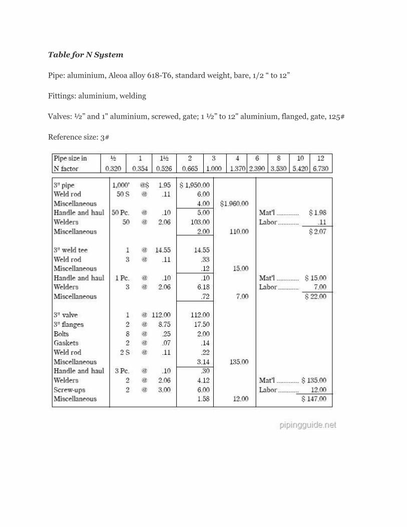
Table for N System
Pipe: aluminium, Aleoa alloy 618-T6, standard weight, bare, 1/2 “ to 12”
Fittings: aluminium, welding
Valves: ½” and 1" aluminium, screwed, gate; 1 ½” to 12" aluminium, flanged, gate, 125#
Reference size: 3#